EP3077792B1 - Messkopf mit beleuchtung - Google Patents
Messkopf mit beleuchtung Download PDFInfo
- Publication number
- EP3077792B1 EP3077792B1 EP14808968.3A EP14808968A EP3077792B1 EP 3077792 B1 EP3077792 B1 EP 3077792B1 EP 14808968 A EP14808968 A EP 14808968A EP 3077792 B1 EP3077792 B1 EP 3077792B1
- Authority
- EP
- European Patent Office
- Prior art keywords
- light
- receiving point
- receiving
- sample
- source
- Prior art date
- Legal status (The legal status is an assumption and is not a legal conclusion. Google has not performed a legal analysis and makes no representation as to the accuracy of the status listed.)
- Active
Links
Images

Classifications
-
- G—PHYSICS
- G01—MEASURING; TESTING
- G01N—INVESTIGATING OR ANALYSING MATERIALS BY DETERMINING THEIR CHEMICAL OR PHYSICAL PROPERTIES
- G01N21/00—Investigating or analysing materials by the use of optical means, i.e. using sub-millimetre waves, infrared, visible or ultraviolet light
- G01N21/17—Systems in which incident light is modified in accordance with the properties of the material investigated
- G01N21/25—Colour; Spectral properties, i.e. comparison of effect of material on the light at two or more different wavelengths or wavelength bands
-
- G—PHYSICS
- G01—MEASURING; TESTING
- G01N—INVESTIGATING OR ANALYSING MATERIALS BY DETERMINING THEIR CHEMICAL OR PHYSICAL PROPERTIES
- G01N21/00—Investigating or analysing materials by the use of optical means, i.e. using sub-millimetre waves, infrared, visible or ultraviolet light
- G01N21/17—Systems in which incident light is modified in accordance with the properties of the material investigated
- G01N21/25—Colour; Spectral properties, i.e. comparison of effect of material on the light at two or more different wavelengths or wavelength bands
- G01N21/255—Details, e.g. use of specially adapted sources, lighting or optical systems
-
- G—PHYSICS
- G01—MEASURING; TESTING
- G01J—MEASUREMENT OF INTENSITY, VELOCITY, SPECTRAL CONTENT, POLARISATION, PHASE OR PULSE CHARACTERISTICS OF INFRARED, VISIBLE OR ULTRAVIOLET LIGHT; COLORIMETRY; RADIATION PYROMETRY
- G01J3/00—Spectrometry; Spectrophotometry; Monochromators; Measuring colours
- G01J3/02—Details
- G01J3/0205—Optical elements not provided otherwise, e.g. optical manifolds, diffusers, windows
- G01J3/0218—Optical elements not provided otherwise, e.g. optical manifolds, diffusers, windows using optical fibers
-
- G—PHYSICS
- G01—MEASURING; TESTING
- G01N—INVESTIGATING OR ANALYSING MATERIALS BY DETERMINING THEIR CHEMICAL OR PHYSICAL PROPERTIES
- G01N21/00—Investigating or analysing materials by the use of optical means, i.e. using sub-millimetre waves, infrared, visible or ultraviolet light
- G01N21/01—Arrangements or apparatus for facilitating the optical investigation
-
- G—PHYSICS
- G01—MEASURING; TESTING
- G01N—INVESTIGATING OR ANALYSING MATERIALS BY DETERMINING THEIR CHEMICAL OR PHYSICAL PROPERTIES
- G01N21/00—Investigating or analysing materials by the use of optical means, i.e. using sub-millimetre waves, infrared, visible or ultraviolet light
- G01N21/01—Arrangements or apparatus for facilitating the optical investigation
- G01N21/03—Cuvette constructions
-
- G—PHYSICS
- G01—MEASURING; TESTING
- G01N—INVESTIGATING OR ANALYSING MATERIALS BY DETERMINING THEIR CHEMICAL OR PHYSICAL PROPERTIES
- G01N21/00—Investigating or analysing materials by the use of optical means, i.e. using sub-millimetre waves, infrared, visible or ultraviolet light
- G01N21/01—Arrangements or apparatus for facilitating the optical investigation
- G01N21/03—Cuvette constructions
- G01N21/031—Multipass arrangements
- G01N2021/0314—Double pass, autocollimated path
-
- G—PHYSICS
- G01—MEASURING; TESTING
- G01N—INVESTIGATING OR ANALYSING MATERIALS BY DETERMINING THEIR CHEMICAL OR PHYSICAL PROPERTIES
- G01N21/00—Investigating or analysing materials by the use of optical means, i.e. using sub-millimetre waves, infrared, visible or ultraviolet light
- G01N21/01—Arrangements or apparatus for facilitating the optical investigation
- G01N21/03—Cuvette constructions
- G01N2021/0346—Capillary cells; Microcells
- G01N2021/035—Supports for sample drops
-
- G—PHYSICS
- G01—MEASURING; TESTING
- G01N—INVESTIGATING OR ANALYSING MATERIALS BY DETERMINING THEIR CHEMICAL OR PHYSICAL PROPERTIES
- G01N21/00—Investigating or analysing materials by the use of optical means, i.e. using sub-millimetre waves, infrared, visible or ultraviolet light
- G01N21/62—Systems in which the material investigated is excited whereby it emits light or causes a change in wavelength of the incident light
- G01N21/63—Systems in which the material investigated is excited whereby it emits light or causes a change in wavelength of the incident light optically excited
- G01N21/64—Fluorescence; Phosphorescence
- G01N2021/6417—Spectrofluorimetric devices
-
- G—PHYSICS
- G01—MEASURING; TESTING
- G01N—INVESTIGATING OR ANALYSING MATERIALS BY DETERMINING THEIR CHEMICAL OR PHYSICAL PROPERTIES
- G01N21/00—Investigating or analysing materials by the use of optical means, i.e. using sub-millimetre waves, infrared, visible or ultraviolet light
- G01N21/62—Systems in which the material investigated is excited whereby it emits light or causes a change in wavelength of the incident light
- G01N21/63—Systems in which the material investigated is excited whereby it emits light or causes a change in wavelength of the incident light optically excited
- G01N21/64—Fluorescence; Phosphorescence
- G01N21/645—Specially adapted constructive features of fluorimeters
- G01N2021/6482—Sample cells, cuvettes
-
- G—PHYSICS
- G01—MEASURING; TESTING
- G01N—INVESTIGATING OR ANALYSING MATERIALS BY DETERMINING THEIR CHEMICAL OR PHYSICAL PROPERTIES
- G01N21/00—Investigating or analysing materials by the use of optical means, i.e. using sub-millimetre waves, infrared, visible or ultraviolet light
- G01N21/62—Systems in which the material investigated is excited whereby it emits light or causes a change in wavelength of the incident light
- G01N21/63—Systems in which the material investigated is excited whereby it emits light or causes a change in wavelength of the incident light optically excited
- G01N21/64—Fluorescence; Phosphorescence
- G01N21/645—Specially adapted constructive features of fluorimeters
- G01N2021/6484—Optical fibres
-
- G—PHYSICS
- G01—MEASURING; TESTING
- G01N—INVESTIGATING OR ANALYSING MATERIALS BY DETERMINING THEIR CHEMICAL OR PHYSICAL PROPERTIES
- G01N21/00—Investigating or analysing materials by the use of optical means, i.e. using sub-millimetre waves, infrared, visible or ultraviolet light
- G01N21/01—Arrangements or apparatus for facilitating the optical investigation
- G01N21/03—Cuvette constructions
- G01N21/0303—Optical path conditioning in cuvettes, e.g. windows; adapted optical elements or systems; path modifying or adjustment
-
- G—PHYSICS
- G01—MEASURING; TESTING
- G01N—INVESTIGATING OR ANALYSING MATERIALS BY DETERMINING THEIR CHEMICAL OR PHYSICAL PROPERTIES
- G01N21/00—Investigating or analysing materials by the use of optical means, i.e. using sub-millimetre waves, infrared, visible or ultraviolet light
- G01N21/01—Arrangements or apparatus for facilitating the optical investigation
- G01N21/11—Filling or emptying of cuvettes
-
- G—PHYSICS
- G01—MEASURING; TESTING
- G01N—INVESTIGATING OR ANALYSING MATERIALS BY DETERMINING THEIR CHEMICAL OR PHYSICAL PROPERTIES
- G01N2201/00—Features of devices classified in G01N21/00
- G01N2201/06—Illumination; Optics
- G01N2201/062—LED's
-
- G—PHYSICS
- G01—MEASURING; TESTING
- G01N—INVESTIGATING OR ANALYSING MATERIALS BY DETERMINING THEIR CHEMICAL OR PHYSICAL PROPERTIES
- G01N2201/00—Features of devices classified in G01N21/00
- G01N2201/06—Illumination; Optics
- G01N2201/063—Illuminating optical parts
- G01N2201/0633—Directed, collimated illumination
-
- G—PHYSICS
- G01—MEASURING; TESTING
- G01N—INVESTIGATING OR ANALYSING MATERIALS BY DETERMINING THEIR CHEMICAL OR PHYSICAL PROPERTIES
- G01N2201/00—Features of devices classified in G01N21/00
- G01N2201/08—Optical fibres; light guides
Definitions
- the present invention relates to a device for the light spectroscopic analysis of a small amount of a liquid sample, with light being guided through the medium and subsequently being detectable or analyzable photometrically, spectrophotometrically, fluorimetrically and spectrofluorimetrically.
- Such devices are, for example, from EP 1 743 162 B1 or the DE 10 2005 036898 A1 known.
- a drop or a very small amount (on the order of less than 10 microliters) of a liquid sample is applied to an upper receiving point.
- the recording point is designed, for example, as a flat recess and is dimensioned according to the small sample volume and is therefore relatively small. It is therefore often difficult for a user to see the recording point with the naked eye, which often means that the liquid sample is only partially applied to the recording point and part of it ends up outside and is therefore not available as an analysis volume and other hand, the device is contaminated.
- the device according to the invention for the light spectroscopic analysis of a small quantity of a liquid sample comprises a light source for exciting the sample, a receiving point in the form of a flat depression on the top of the device for applying a small amount of the liquid sample of less than 10 ⁇ l volume or 10 mg mass, and light guides that are designed to To guide excitation light from the light source to the sample and signal light from the sample for subsequent detection and analysis, with a light-emitting diode being provided as an illumination source directly below the recording point, which is an additional light source to the light source and is not used for spectroscopic excitation, and directly below the recording point an area is provided which extends from the illumination source to the underside of the recording point and is permeable to the light from the illumination source, so that the illumination light suitably illuminates the recording point for better visibility and precise identification of the recording point for the human eye, with along the vertical projection of the recording point, there is no area that guides the illumination light, and the area that
- the receiving site which is a flat depression at the top of the device, is as shown in FIG EP 1 743 162 B1 is described, or a solid surface in the form of an anvil as in EP 1 210 579 B1 discloses is backlit (below) so that the user can accurately identify the pick-up site and, upon dripping, applies the sample with greater certainty within the confines of the pick-up site, so that on the one hand no sample volume is lost and on the other hand the top of the device is not contaminated. Under small amounts, sample amounts of less than 10 ⁇ l volume or 10mg mass are allowed understand, the sampling point must therefore be sized and configured accordingly.
- the light guides are preferably glass fibers, which lead light from a light source, such as a xenon lamp, to the recording point, so that the light can pass through the sample a first time, is reflected by the reflector and can pass through the sample a second time.
- the resulting signal light carries the spectroscopic signature of the sample and is guided by a light guide away from the recording point to a detector, for example a spectrometer.
- the illumination source provided under the recording point is a light source that is additional to the light source and is not used for spectroscopic excitation, but rather to illuminate the recording point that is suitable for the human eye.
- the illuminating light passes through an area directly below the recording point, which is permeable to the illuminating light so that it can reach the recording point.
- this area extends from the illumination source to the recording point or its underside. Since the recording point for the light spectroscopic analysis must be transparent in order to allow both incoming light and signal light to pass through, the illuminating light can also pass through the recording point and ensure the visibility of the recording point for the user.
- illumination is to be understood as meaning both the complete illumination of the recording point and the partial illumination, for example only of the edge of the recording point.
- the receiving point itself is made of transparent material, while the material adjoining the side of the receiving point, e.g. on the top of the device or a housing or on the sides of an anvil on which the recording site is not optically transparent, e.g. suitably blackened.
- the translucent area is arranged directly below the recording point. This includes both areas directly vertically below the recording site, as well as areas that are below but laterally offset from the recording site. According to the invention, there are no areas guiding the illuminating light along the vertical projection of the recording point, for example because incident light and signal light are there There are leading optical fibers, but the areas that are located on the side of said projection are transparent and thus guide the illuminating light obliquely upwards to the recording point.
- the device further comprises a reflector provided above the receiving point, which can be pivoted or detachable for opening and closing, the receiving point being located on the upper side of the device in the position of use.
- the device can optionally also include a housing, on the upper side of which the receiving point is located in the position of use and on which the reflector is pivotable or detachable.
- “Use position” is to be understood as meaning the orientation of the device in which the liquid sample can be applied or dripped onto the recording site, but also the preferred orientation in which the device is arranged within a spectrometer.
- the reflector is preferably installed in a cover that can be plugged, screwed or pivoted via a hinge onto the top of the device or housing, with other fastening options, including the use of fixing elements such as screws or pins, being conceivable. It is essential that the reflector and possibly the cover with it can be opened in order to gain access to the receiving point from above and closed so that the reflector forms a sample volume with the receiving point that is filled by the sample liquid.
- the receiving point is a receiving surface and a movable surface is provided opposite the receiving surface, which can move towards the receiving surface so that the liquid sample is inserted between the receiving surface and the movable surface.
- the receiving surface may be located on the top of an anvil, and one light guide may guide light through the movable surface to the sample, while another light guide guides the signal light through the receiving surface to the detector.
- the illumination source is a real or virtual light source.
- a directly light-emitting diode LED
- the direct light-generating source is located below the receiving point in the housing.
- the actual light source for example an LED
- the illumination light from the illumination source is transmitted using a light guide, such as a glass fiber , up below the Recording point (e.g. in the housing) out, where the end of the light guide represents the virtual source of illumination.
- the light-transmitting area is particularly preferably a transparent part of the housing.
- the area of the housing that receives the light guide ends directly below the receiving point can be made transparent for this purpose.
- the light-transmissive area is a small glass tube extending from the receiving point to the illumination source. This tube thus leads the illuminating light through light conduction directly from the lighting to the recording point.
- the light-transmitting area can also be a hole whose clear width is not completely filled by the light guides. This creates space around the light guides through which the illuminating light can reach the recording point from below.
- the lighting source is a light-emitting diode as a real light source located directly below the recording point (e.g. in the housing).
- the light-emitting diode can have a different color, but white is generally preferred for illumination. It is also conceivable that the light-emitting diode can change its color according to specific operating modes.
- the light guide supplying the light can be used twice, firstly to excite the sample in the recording point and secondly to illuminate the recording point.
- the illumination source is expediently arranged at the entrance of the light-supplying light guide in such a way that its focal point at the other end of the light guide does not coincide with that of the light source (which is inside the sample in the recording point), so that the illuminating light at the recording point already diverges enough to illuminate the recording point.
- the device further comprises a reflector provided above the receiving point, which can be pivoted or detachable for opening and closing, the receiving point being located on the upper side of the device in the position of use.
- the device can optionally also include a housing, on the upper side of which the receiving point is located in the position of use and on which the reflector is pivotable or detachable.
- the receiving site may be a receiving surface and a movable surface may be provided opposite the receiving surface, which movable surface may move toward the receiving surface so that the liquid sample is sandwiched between the receiving surface and the movable surface.
- a fiber optic connector is particularly preferably provided at the entrance of the light guide that supplies the light, and the illumination source is arranged directly on the connector.
- the illumination source for example a light emitting diode, can be placed in the gap between the light source (for example a xenon lamp) and the fiber connector (for example a SMA connector).
- the illumination source and the light source are integrated or combined. This means that with a light source itself, e.g. a combined halogen/deuterium lamp, both the illumination of the recording site (e.g. by means of a dimmed halogen lamp) and the irradiation of the light for the analysis is effected.
- a light source itself, e.g. a combined halogen/deuterium lamp
- both the illumination of the recording site e.g. by means of a dimmed halogen lamp
- the irradiation of the light for the analysis is effected.
- FIG 1 a sectional view of a first preferred embodiment of the device according to the invention is shown.
- the device for the light spectroscopic analysis of a small amount of a liquid sample is presently a measuring head 1 which comprises an elongate housing 2 with a sample holder 13 on the upper side (in the use position, ie a vertical, upright orientation of the elongate housing 2).
- the sample receptacle 13 is ring-shaped and surrounds a receptacle point 3 designed as a flat depression (see the enlargement at "Z" in 1 ).
- the receiving point is accessible from above and allows the liquid sample to be applied, which is held at the receiving point 3 by gravity.
- the bottom 18 of the recording point 3 is formed, for example, by a material that is transparent to the excitation signal light, such as quartz glass, which can also have lens features depending on the light guide used, as is shown in FIG EP 1 743 162 B1 is described.
- the receiving point is closed from above with a cover 14 which has a reflector 4 on its underside, which closes the receiving point flush with the annular sample receptacle from above and thus forms a defined sample volume.
- a glass fiber 5 is used, which is connected via an SMA connector 15 with a (in 1 not shown) light source is connected, light out to the underside of the recording site.
- the light then traverses the sample volume, is reflected by the reflector 4, traverses the sample volume again and is then passed as signal light from the glass fiber 6 to a detector, also not shown here, for example a spectrometer, to which the fiber 6 is connected via an SMA connector 16 is connected.
- the ends of the glass fibers 5 and 6 facing the recording point are glued in a feed sleeve 9 in such a way that the light exiting or entering them has an ideal focal point in the sample volume.
- the glass fibers 5, 6 are guided in the inner cavity 12 of the housing 2.
- the LED 7 can reach the underside of the receiving point 3 through a transparent area 8, which is presently configured as a small glass tube 8 surrounding the feed sleeve 9, and thus illuminate the receiving point from below.
- the illumination light from the LED 7 enters the glass tube 8, which directs the illumination light to the floor 18 in the receiving location 3 and thus to its underside.
- the feed sleeve 9 of the optical fibers 5, 6 transparent and to use it as a transparent area for the light transmission of the illumination light to the receiving point 3.
- a possible scattering of the illumination light in the optical fibers 5, 6 is not critical since the illumination is switched off during the measurement, as will be explained below.
- a switching mechanism can also be provided which switches on the lighting by the LED 7 only when the cover 14 is removed and automatically deactivates the LED 7 after the cover 14 with the reflector 4 has been placed on the receiving location 3, ie has been closed.
- the lighting is therefore switched off when the lid is closed and in particular during the measurements, and any impairment of the measurement results is effectively prevented.
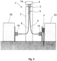
- FIG 2 there is shown a second preferred embodiment of the present invention.
- the device for light spectroscopic analysis of a small amount of a liquid sample is a measuring head 1 ', which is essentially the embodiment of figure 1 corresponds.
- no LED is provided below the receiving point 3, nor is there an area that is transparent to the illuminating light, as in the first embodiment.
- a light-emitting diode or a halogen lamp 7 ′ is present as an illumination light source between a fiber-optic connector 15 of the optical fiber 5 leading the light to the recording point and a xenon lamp 20 , which represents the light source, and is connected via a power supply line 17 .
- the light from the LED 7 ′ is coupled into the optical fiber 5 and guided to the receiving point 3 .
- the light from the LED or halogen lamp 7' is coupled in such a way that the focal point of the illumination light at the other end of the fiber 5 is outside of the recording point 3 or the sample volume in it, so that the Illumination light beam at the recording point 3 already diverges enough to illuminate the recording point 3.
- the LED 7' is switched off, so that neither the excitation light nor the signal light, which is coupled into the spectrometer (detector) 30 through the glass fiber 6 via an SMA connection 16, is not adversely affected.
Landscapes
- Physics & Mathematics (AREA)
- General Physics & Mathematics (AREA)
- Biochemistry (AREA)
- Life Sciences & Earth Sciences (AREA)
- Chemical & Material Sciences (AREA)
- Analytical Chemistry (AREA)
- Health & Medical Sciences (AREA)
- General Health & Medical Sciences (AREA)
- Immunology (AREA)
- Pathology (AREA)
- Spectroscopy & Molecular Physics (AREA)
- Investigating Or Analysing Materials By Optical Means (AREA)
- Investigating, Analyzing Materials By Fluorescence Or Luminescence (AREA)
Description
- Die vorliegende Erfindung betrifft eine Vorrichtung für die lichtspektroskopische Analyse an einer kleinen Menge einer flüssigen Probe, wobei Licht durch das Medium geführt wird und anschließend photometrisch, spektralphotometrisch, fluorimetrisch und spektralfluorimetrisch detektierbar oder analysierbar ist.
- Derartige Vorrichtungen sind beispielsweise aus der
EP 1 743 162 B1 oder derDE 10 2005 036898 A1 bekannt. Bei den dort beschriebenen Vorrichtungen wird ein Tropfen bzw. eine kleinste Menge (der Größenordnung von unter 10 Mikrolitern) einer flüssigen Probe auf eine obere Aufnahmestelle aufgebracht. Die Aufnahmestelle ist beispielsweise als flächige Vertiefung ausgestaltet und ist dem kleinen Probenvolumen entsprechend dimensioniert und somit relativ klein. Daher ist es für einen Benutzer oftmals schwierig, die Aufnahmestelle mit bloßem Auge genau zu sehen, was häufig dazu führt, dass die flüssige Probe nur teilweise auf die Aufnahmestelle aufgebracht wird und ein Teil davon außerhalb landet und dadurch einerseits nicht als Analysevolumen zur Verfügung steht und andererseits die Vorrichtung verunreinigt. - Auch in Vorrichtungen wie jenen, die in
EP 1 210 579 B1 ,US 2010/085571 A1 oder dem Artikel von F. Pena-Pereira et al. "Advances in miniaturized UV-Vis spectroscopic systems", TRENDS IN ANALYTICAL CHEMISTRY Bd. 30, Nr. 10, S. 1637-1648 beschrieben sind und bei denen ein Tropfen einer flüssigen Probe zwischen zwei aufeinander zu bewegliche Aufnahmeflächen aufgrund seiner Oberflächenspannung ohne weitere Begrenzung frei gehalten wird, ergibt sich das Problem, dass die den Tropfen aufnehmende Fläche nur schwer mit bloßem Auge erkennbar ist. - Aus dem Stand der Technik, beispielsweise der
US 2006/0 051 036 A1 sind faseroptische Endoskope bekannt, die außer der Führung des Anregungslichts für spektroskopische Analysen auch weißes Licht zur Abbildung von endoskopisch zu beobachtendem Gewebe führen. Allerdings sind diese Geräte nicht zur Aufnahme kleinster Flüssigkeitsmengen ausgestaltet, da sie keine entsprechende Aufnahmestelle besitzen und somit auch keine Probeaufnahme ausleuchten können. - Es ist somit Aufgabe der vorliegenden Erfindung, eine gattungsgemäße Vorrichtung für die lichtspektroskopische Analyse einer kleinen Menge einer flüssigen Probe so weiterzubilden, dass die Sichtbarkeit der oberen flächigen Aufnahmestelle verbessert und die Handhabung damit vereinfacht und weniger anfällig für Fehler gemacht wird. Diese Aufgabe wird mithilfe einer Vorrichtung für die lichtspektroskopische Analyse einer kleinen Menge einer flüssigen Probe mit den Merkmalen der Ansprüche 1 bzw. 6 gelöst. Weitere Merkmale und vorteilhafte Ausgestaltungen ergeben sich aus den Unteransprüchen.
- Die erfindungsgemäße Vorrichtung für die lichtspektroskopische Analyse einer kleinen Menge einer flüssigen Probe ist in den Ansprüchen 1 und 6 definiert. Gemäß einem ersten Aspekt umfasst sie eine Lichtquelle zur Anregung der Probe, eine Aufnahmestelle in Form einer flächigen Vertiefung an der Oberseite der Vorrichtung zum Aufbringen einer kleinen Menge der flüssigen Probe von unter 10µl Volumen bzw. 10mg Masse, und Lichtleiter, die ausgebildet sind, um Anregungslicht von der Lichtquelle zur Probe und Signallicht aus der Probe zur anschließenden Detektion und Analyse zu leiten, wobei unmittelbar unterhalb der Aufnahmestelle eine Leuchtdiode als Beleuchtungsquelle vorgesehen ist, die eine zur Lichtquelle zusätzliche Lichtquelle ist und nicht der spektroskopischen Anregung dient, und unmittelbar unter der Aufnahmestelle ein Bereich vorgesehen ist, der sich von der Beleuchtungsquelle bis zur Unterseite der Aufnahmestelle erstreckt und für das Licht der Beleuchtungsquelle durchlässig ist, so dass das Beleuchtungslicht die Aufnahmestelle zur besseren Sichtbarkeit und genauen Identifikation der Aufnahmestelle für das menschliche Auge geeignet ausleuchtet, wobei entlang der vertikalen Projektion der Aufnahmestelle kein das Beleuchtungslicht führender Bereich vorhanden ist, und der Bereich, der sich seitlich der genannten Projektion befindet, geeignet ist, das Beleuchtungslicht schräg nach oben zur Aufnahmestelle zu leiten.
- Wenn ein Benutzer nun eine kleine Menge, zum Beispiel einen Tropfen, einer flüssigen Probe auf die Aufnahmestelle aufbringen will, wird die Aufnahmestelle, welche eine flächige Vertiefung an der Oberseite der Vorrichtung ist, wie es in der
EP 1 743 162 B1 beschrieben ist, oder aber eine feste Fläche in Form eines Ambosses wie in derEP 1 210 579 B1 offenbart, von hinten (unten) beleuchtet, so dass der Benutzer die Aufnahmestelle genau identifizieren kann und beim Auftropfen die Probe mit höherer Sicherheit innerhalb der Begrenzung der Aufnahmestelle aufbringt, so dass einerseits kein Probenvolumen verloren geht und andererseits die Oberseite der Vorrichtung nicht verunreinigt wird. Unter kleinen Mengen sind Probenmengen von unter 10µl Volumen bzw. 10mg Masse zu verstehen, die Probeaufnahmestelle muss daher entsprechend bemessen und konfiguriert sein. - Die Lichtleiter sind hierbei bevorzugt Glasfasern, welche Licht von einer Lichtquelle, wie zum Beispiel einer Xenonlampe, zur Aufnahmestelle führen, so dass das Licht durch die Probe ein erstes Mal durchtreten kann, vom Reflektor reflektiert wird und ein zweites Mal durch die Probe hindurchtreten kann. Das dabei entstehende Signallicht trägt die spektroskopische Signatur der Probe und wird von einem Lichtleiter von der Aufnahmestelle weg zu einem Detektor, beispielsweise einem Spektrometer, geführt.
- Die unter der Aufnahmestelle vorgesehene Beleuchtungsquelle ist dabei eine zur Lichtquelle zusätzliche Lichtquelle, welche nicht der spektroskopischen Anregung dient, sondern der für das menschliche Auge geeigneten Ausleuchtung der Aufnahmestelle. Das Beleuchtungslicht tritt hierfür durch einen Bereich unmittelbar unter der Aufnahmestelle hindurch, welcher für das Beleuchtungslicht durchlässig ist, so dass dieses zur Aufnahmestelle gelangen kann. Erfindungsgemäß erstreckt sich dieser Bereich von der Beleuchtungsquelle bis zur Aufnahmestelle bzw. deren Unterseite. Da die Aufnahmestelle für die lichtspektroskopische Analyse transparent sein muss, um sowohl eingehendes Licht als auch Signallicht durchtreten zu lassen, kann so auch das Beleuchtungslicht durch die Aufnahmestelle hindurch gelangen und die Sichtbarkeit der Aufnahmestelle für den Benutzer gewährleisten.
- Unter Ausleuchten ist hierbei sowohl das vollständige Ausleuchten der Aufnahmestelle wie auch das teilweise Ausleuchten, beispielsweise nur des Randes der Aufnahmestelle zu verstehen. Zur besseren Sichtbarkeit der Aufnahmestelle ist weiterhin denkbar, dass lediglich die Aufnahmestelle an sich aus transparentem Material hergestellt ist, während das sich seitlich an die Aufnahmestelle anschließende Material, z.B. an der Oberseite der Vorrichtung oder eines Gehäuses oder an den Seiten eines Ambosses, auf dem sich die Aufnahmestelle befindet, nicht optisch transparent ist, beispielsweise geeignet geschwärzt ist.
- Im Sinne der Erfindung ist der lichtdurchlässige Bereich unmittelbar unter der Aufnahmestelle angeordnet. Dies schließt sowohl Bereiche unmittelbar vertikal unter der Aufnahmestelle ein, als auch Bereiche, die sich unterhalb aber seitlich versetzt zur Aufnahmestelle befinden. Erfindungsgemäß sind entlang der vertikalen Projektion der Aufnahmestelle keine das Beleuchtungslicht führenden Bereiche vorhanden, beispielsweise weil sich dort Einfalls- und Signallicht
führende Lichtleitfasern befinden, aber die Bereiche, die sich seitlich der genannten Projektion befinden, transparent sind und das Beleuchtungslicht somit schräg nach oben zur Aufnahmestelle leiten. - Bevorzugt umfasst die Vorrichtung weiter einen oberhalb der Aufnahmestelle vorgesehenen, zum Öffnen bzw. Schließen verschwenkbaren bzw. lösbaren Reflektor, wobei sich die Aufnahmestelle in Gebrauchsstellung an der Oberseite der Vorrichtung befindet. Die Vorrichtung kann optional entsprechend auch ein Gehäuse umfassen, an dessen Oberseite sich die Aufnahmestelle in Gebrauchsstellung befindet und an dem der Reflektor verschwenkbar bzw. lösbar vorgesehen ist.
- Unter "Gebrauchsstellung" ist dabei die Orientierung der Vorrichtung zu verstehen, bei der zum einen die flüssige Probe auf die Aufnahmestelle aufgebracht bzw. aufgetropft werden kann, zum anderen aber auch die bevorzugte Orientierung, in welcher die Vorrichtung innerhalb eines Spektrometers angeordnet ist. Im Allgemeinen bedeutet dies, dass die beispielsweise längliche Vorrichtung oder deren Gehäuse, an deren/dessen Oberseite die Aufnahmestelle vorgesehen und mit dem verschwenkbaren bzw. lösbaren Reflektor abgedeckt ist, sich in einer aufrechten bzw. vertikalen Orientierung befindet. Der Reflektor ist dabei bevorzugt in einem Deckel eingebaut, der auf die Oberseite der Vorrichtung bzw. des Gehäuses aufsteckbar, aufschraubbar oder über ein Scharnier verschwenkbar angebracht ist, wobei weitere Befestigungsmöglichkeiten, auch unter Zuhilfenahme von Fixierelementen wie Schrauben oder Stiften denkbar sind. Wesentlich ist, dass der Reflektor und ggf. mit ihm der Deckel geöffnet werden kann, um Zugang zur Aufnahmestelle von oben zu erhalten, und geschlossen werden kann, damit der Reflektor mit der Aufnahmestelle ein Probenvolumen bildet, das von der Probenflüssigkeit ausgefüllt wird.
- Gemäß einer alternativen Ausgestaltung ist denkbar, dass die Aufnahmestelle eine Aufnahmefläche ist und der Aufnahmefläche gegenüber eine bewegliche Fläche vorgesehen ist, welche sich auf die Aufnahmefläche zubewegen kann, so dass die flüssige Probe zwischen der Aufnahmefläche und der beweglichen Fläche eingelegt wird. Die Aufnahmefläche kann beispielsweise an der Oberseite eines Ambosses angeordnet sein, und ein Lichtleiter kann Licht durch die bewegliche Fläche hindurch zur Probe führen, während ein weiterer Lichtleiter das Signallicht durch die Aufnahmefläche hindurch zum Detektor führt.
- Erfindungsgemäß ist die Beleuchtungsquelle eine reale oder virtuelle Lichtquelle. Im Fall der realen Beleuchtungsquelle gemäß Anspruch 1 befindet sich unterhalb der Aufnahmestelle eine direkt lichterzeugende Leuchtdiode (LED), die zum Beispiel im Wesentlichen weißes Licht aussendet, so dass die Aufnahmestelle weiß ausgeleuchtet wird. Ist ein Gehäuse vorgesehen, befindet sich die direkt lichterzeugende Quelle unterhalb der Aufnahmestelle im Gehäuse.
- Im Falle einer virtuellen Lichtquelle gemäß Anspruch 6 befindet sich die tatsächliche Lichtquelle, zum Beispiel eine LED, an einer vom Ort unter der Aufnahmestelle, insbesondere an einer vom Gehäuse entfernten Position, und das Beleuchtungslicht der Beleuchtungsquelle wird mithilfe eines Lichtleiters, wie zum Beispiel einer Glasfaser, bis unterhalb der Aufnahmestelle (z.B. in das Gehäuse) geführt, wo das Ende des Lichtleiters die virtuelle Beleuchtungsquelle darstellt.
- Besonders bevorzugt ist der lichtdurchlässige Bereich ein transparenter Teil des Gehäuses. Beispielsweise kann hierfür der Bereich des Gehäuses, der die Lichtleiterenden unmittelbar unterhalb der Aufnahmestelle aufnimmt, transparent ausgestaltet sein.
- Besonders bevorzugt hierbei ist, dass der lichtdurchlässige Bereich ein sich von der Aufnahmestelle zur Beleuchtungsquelle erstreckendes Glasröhrchen ist. Dieses Röhrchen führt somit das Beleuchtungslicht durch Lichtleitung direkt von der Beleuchtung zur Aufnahmestelle.
- Alternativ kann der lichtdurchlässige Bereich auch eine Bohrung sein, deren lichte Weite nicht vollständig von den Lichtleitern ausgefüllt ist. So wird um die Lichtleiter herum Raum geschaffen, durch den das Beleuchtungslicht von unten zur Aufnahmestelle gelangen kann. Im Allgemeinen ist bevorzugt, dass die Beleuchtungsquelle eine unmittelbar unterhalb der Aufnahmestelle (z.B. im Gehäuse) befindliche Leuchtdiode als reale Lichtquelle ist. Die Leuchtdiode kann dabei je nach Bedarf eine unterschiedliche Farbe besitzen, im Allgemeinen wird jedoch Weiß zur Ausleuchtung bevorzugt sein. Ebenso ist denkbar, dass die Leuchtdiode ihre Farbe entsprechend bestimmter Betriebsmodi ändern kann.
- In einem zweiten Aspekt ist eine erfindungsgemäße Vorrichtung für die lichtspektroskopische Analyse einer kleinen Menge einer flüssigen Probe vorgesehen, umfassend eine Lichtquelle zur Anregung der Probe, eine Aufnahmestelle zum Aufbringen der flüssigen Probe von unter 10µl Volumen bzw. 10mg Masse, und Lichtleiter, die ausgebildet sind, um Anregungslicht von der Lichtquelle zur Probe und Signallicht aus der Probe zur anschließenden Detektion und Analyse zu leiten, wobei am Eingang des Licht zuführenden Lichtleiters eine Beleuchtungsquelle vorgesehen ist, die eine zur Lichtquelle zusätzliche Lichtquelle ist und nicht der spektroskopischen Anregung dient, welche Beleuchtungslicht in diesen Lichtleiter so einkoppelt, dass der Fokuspunkt des Beleuchtungslichts am Ausgang des Licht zuführenden Lichtleiters außerhalb der Aufnahmestelle bzw, des Probenvolumens in ihr liegt und so die Aufnahmestelle zur besseren Sichtbarkeit und genauen Identifikation der Aufnahmestelle für das menschliche Auge geeignet ausleuchtet. Auf diese Weise kann der das Licht zuführende Lichtleiter doppelt genutzt werden, einmal zum Anregen der Probe in der Aufnahmestelle, und zum anderen zum Ausleuchten der Aufnahmestelle. Zweckmäßig wird hierfür die Beleuchtungsquelle so am Eingang des Lichts zuführenden Lichtleiters angeordnet, dass ihr Fokuspunkt am anderen Endes des Lichtleiters nicht mit jenem der Lichtquelle (welcher innerhalb der Probe in der Aufnahmestelle liegt) zusammenfällt, so
dass das Beleuchtungslicht an der Aufnahmestelle bereits genügend divergiert, um die Aufnahmestelle auszuleuchten. - Bevorzugt umfasst die Vorrichtung weiter einen oberhalb der Aufnahmestelle vorgesehenen, zum Öffnen bzw. Schließen verschwenkbaren bzw. lösbaren Reflektor, wobei sich die Aufnahmestelle in Gebrauchsstellung an der Oberseite der Vorrichtung befindet. Die Vorrichtung kann optional entsprechend auch ein Gehäuse umfassen, an dessen Oberseite sich die Aufnahmestelle in Gebrauchsstellung befindet und an dem der Reflektor verschwenkbar bzw. lösbar vorgesehen ist.
- Wie im ersten Aspekt kann alternativ die Aufnahmestelle eine Aufnahmefläche sein und der Aufnahmefläche gegenüber eine bewegliche Fläche vorgesehen sein, welche sich auf die Aufnahmefläche zubewegen kann, so dass die flüssige Probe zwischen der Aufnahmefläche und der beweglichen Fläche eingelegt wird.
- Besonders bevorzugt ist am Eingang des das Licht zuführenden Lichtleiters ein faseroptischer Verbinder vorgesehen und die Beleuchtungsquelle unmittelbar am Verbinder angeordnet. Auf diese Weise kann die Beleuchtungsquelle, zum Beispiel eine Leuchtdiode, in den Spalt zwischen der Lichtquelle (zum Beispiel einer Xenonlampe) und dem Faserverbinder (beispielsweise einem SMA-Verbinder) angeordnet sein.
- Schließlich sind in einer möglichen Ausführungsform der Vorrichtung die Beleuchtungsquelle und die Lichtquelle integriert bzw. kombiniert. Dies bedeutet, dass mit einer Lichtquelle an sich, z.B. einer kombinierten Halogen/Deuterium-Lampe, sowohl die Beleuchtung der Aufnahmestelle (beispielsweise mittels gedimmter Halogenlampe) als auch die Einstrahlung des Lichts zur Analyse bewirkt wird.
- Im Folgenden werden zwei Ausführungsbeispiele der vorliegenden Erfindung mit Bezug auf die beigefügten Zeichnungen beschrieben.
- Fig. 1
- zeigt eine Schnittansicht einer ersten bevorzugten Ausführungsform der erfindungsgemäßen Vorrichtung, bei welcher eine Leuchtdiode unterhalb der Aufnahmestelle vorgesehen ist; und
- Fig. 2
- zeigt eine zweite bevorzugte Ausführungsform der erfindungsgemäßen Vorrichtung, bei der eine Leuchtdiode am Ende der das Licht zuführenden Lichtleitfaser vorgesehen ist.
- In
Figur 1 ist eine Schnittansicht einer ersten bevorzugten Ausführungsform der erfindungsgemäßen Vorrichtung dargestellt. Die Vorrichtung für die lichtspektroskopische Analyse einer kleinen Menge einer flüssigen Probe ist vorliegend ein Messkopf 1, welcher ein längliches Gehäuse 2 umfasst, an dessen Oberseite (in Gebrauchsstellung, d. h. einer vertikalen, aufrechten Orientierung des länglichen Gehäuses 2) sich eine Probenaufnahme 13 befindet. Die Probenaufnahme 13 ist ringförmig ausgebildet und umgibt eine als flächige Vertiefung ausgebildete Aufnahmestelle 3 (siehe die Vergrößerung bei "Z" inFig. 1 ). Die Aufnahmestelle ist von oben zugänglich und erlaubt das Aufbringen der flüssigen Probe, welche durch Schwerkraft an der Aufnahmestelle 3 gehalten wird. Der Boden 18 der Aufnahmestelle 3 wird beispielsweise durch ein für das Anregungs- zum Signallicht transparentes Material gebildet, wie zum Beispiel Quarzglas, welches je nach der verwendeten Lichtführung auch Linsenmerkmale besitzen kann, wie es in derEP 1 743 162 B1 beschrieben ist. Die Aufnahmestelle wird nach Aufbringen der Probe von oben mit einem Deckel 14 verschlossen, welcher an seiner Unterseite einen Reflektor 4 aufweist, der die Aufnahmestelle von oben bündig mit der ringförmigen Probenaufnahme abschließt und somit ein definiertes Probenvolumen bildet. - Zur Anregung der Probe wird mithilfe einer Glasfaser 5, welche über einen SMA-Anschluss 15 mit einer (in
Fig. 1 nicht dargestellten) Lichtquelle verbunden ist, Licht bis an die Unterseite der Aufnahmestelle geführt. Das Licht durchquert dann das Probenvolumen, wird vom Reflektor 4 reflektiert, durchquert das Probenvolumen erneut und wird anschließend als Signallicht von der Glasfaser 6 zu einem hier ebenfalls nicht gezeigten Detektor, beispielsweise ein Spektrometer, geführt, an welches die Faser 6 über einen SMA-Anschluss 16 angeschlossen wird. Die zur Aufnahmestelle gewandten Enden der Glasfasern 5 und 6 sind in einer Zuführhülse 9 so verklebt, dass das aus ihnen austretende bzw. in sie eintretende Licht jeweils einen idealen Fokuspunkt im Probenvolumen besitzt. Die Glasfasern 5, 6 werden dabei im inneren Hohlraum 12 des Gehäuses 2 geführt. - Unterhalb der Aufnahmestelle befindet sich im oberen Teil des Hohlraums 12 des Gehäuses 2 eine Leuchtdiode 7, deren Stromversorgung über ein Versorgungskabel 17 mit entsprechendem Stecker gewährleistet wird, das ebenfalls durch den Hohlraum 12 des Gehäuses 2 geführt ist. Das von der LED 7 abgestrahlte Licht kann dabei durch einen transparenten Bereich 8, der vorliegend als die Zuführhülse 9 umgebendes Glasröhrchen 8 ausgestaltet ist, bis an die Unterseite der Aufnahmestelle 3 gelangen und so die Aufnahmestelle von unten ausleuchten. Im vorliegenden Ausführungsbeispiel tritt also das Beleuchtungslicht aus der LED 7 in das Glasröhrchen 8 ein, welches das Beleuchtungslicht zum Boden 18 in der Aufnahmestelle 3 und somit zu deren Unterseite leitet.
- Alternativ ist es auch denkbar, die Zuführhülse 9 der Lichtleitfasern 5, 6 transparent zu gestalten und als transparenter Bereich für die Lichtleitung des Beleuchtungslichts zur Aufnahmestelle 3 einzusetzen. Eine eventuelle Streuung des Beleuchtungslichts in die Lichtleitfasern 5, 6 ist dabei unkritisch, da die Beleuchtung bei der Messung abgeschaltet wird, wie im Folgenden noch erläutert wird.
- Obwohl es in
Figur 1 nicht dargestellt ist, kann weiterhin ein Schaltmechanismus vorgesehen sein, welcher die Beleuchtung durch die LED 7 nur bei abgenommenem Deckel 14 einschaltet und die LED 7 automatisch deaktiviert, nachdem der Deckel 14 mit dem Reflektor 4 auf die Aufnahmestelle 3 aufgesetzt, d. h. verschlossen wurde. Somit ist die Beleuchtung bei geschlossenem Deckel und insbesondere während der Messungen abgeschaltet, und jegliche Beeinträchtigung der Messergebnisse wird wirkungsvoll verhindert. - In
Figur 2 ist eine zweite bevorzugte Ausführungsform der vorliegenden Erfindung gezeigt. Hierbei ist die Vorrichtung zur lichtspektroskopischen Analyse einer kleinen Menge einer flüssigen Probe ein Messkopf 1', der im Wesentlichen der Ausführungsform derFigur 1 entspricht. Allerdings ist vorliegend keine LED unterhalb der Aufnahmestelle 3 vorgesehen, ebenso wenig wie ein das Beleuchtungslicht durchlässiger Bereich wie in der ersten Ausführungsform. Stattdessen ist vorliegend eine Leuchtdiode oder eine Halogenlampe 7' als Beleuchtungslichtquelle zwischen einem faseroptischen Verbinder 15 der das Licht zur Aufnahmestelle führenden Lichtleitfaser 5 und einer Xenonlampe 20, welche die Lichtquelle darstellt, angeordnet und über eine Stromversorgungleitung 17 angeschlossen. Das Licht der LED 7' wird dabei in die Lichtleiterfaser 5 eingekoppelt und zur Aufnahmestelle 3 geführt. Hierbei wird das Licht der LED oder Halogenlampe 7' so eingekoppelt, dass der Fokuspunkt des Beleuchtungslichts am anderen Ende der Faser 5 außerhalb der Aufnahmestelle 3 bzw. des Probenvolumens in ihr liegt, so dass der Beleuchtungslichtstrahl an der Aufnahmestelle 3 bereits genügend divergiert, um die Aufnahmestelle 3 auszuleuchten. - Wie in der ersten Ausführungsform wird bei der Messung, d. h. bei aufgesetztem Deckel 14, die LED 7' abgeschaltet, so dass weder das Anregungsglicht noch das Signallicht, welches durch die Glasfaser 6 über einen SMA-Anschluss 16 in das Spektrometer (Detektor) 30 gekoppelt wird, nicht negativ beeinträchtigt wird.
Claims (10)
- Vorrichtung (1) für die lichtspektroskopische Analyse einer kleinen Menge einer flüssigen Probe, umfassend:eine Lichtquelle zur Anregung der Probe;eine Aufnahmestelle (3) in Form einer flächigen Vertiefung an der Oberseite der Vorrichtung oder einer festen Fläche in Form eines Ambosses, die zum Aufbringen einer kleinen Menge der flüssigen Probe von unter 10µl Volumen bzw. 10mg Masse bemessen und konfiguriert ist, undLichtleiter (5, 6), die ausgebildet sind, um Anregungslicht von der Lichtquelle zur Probe und Signallicht aus der Probe zur anschließenden Detektion und Analyse zu leiten,dadurch gekennzeichnet, dass unmittelbar unterhalb der Aufnahmestelle (3) eine Leuchtdiode als Beleuchtungsquelle (7) vorgesehen ist, die eine zur Lichtquelle zusätzliche Lichtquelle ist und nicht der spektroskopischen Anregung dient, und unmittelbar unter der Aufnahmestelle (3) ein Bereich (8) vorgesehen ist, der sich von der Beleuchtungsquelle (7) bis zur Unterseite der Aufnahmestelle (3) erstreckt und für das Licht der Beleuchtungsquelle (7) durchlässig ist, so dass das Beleuchtungslicht die Aufnahmestelle (3) zur besseren Sichtbarkeit und genauen Identifikation der Aufnahmestelle (3) für das menschliche Auge geeignet ausleuchtet,wobei entlang der vertikalen Projektion der Aufnahmestelle (3) kein das Beleuchtungslicht führender Bereich vorhanden ist, und der Bereich, der für das Licht der Beleuchtungsquelle (7) durchlässig ist, sich seitlich der genannten Projektion befindet und geeignet ist, das Beleuchtungslicht schräg nach oben zur Aufnahmestelle (3) zu leiten
- Vorrichtung (1) nach Anspruch 1, weiter umfassend:
einen oberhalb der Aufnahmestelle (3) vorgesehenen, zum Zugänglichmachen der Aufnahmestelle (3) verschwenkbaren oder lösbaren Reflektor (4), wobei sich die Aufnahmestelle (3) in Gebrauchsstellung an der Oberseite der Vorrichtung (1) befindet - Vorrichtung (1) nach Anspruch 1, wobei die Aufnahmestelle (3) eine Aufnahmefläche ist und der Aufnahmefläche gegenüber eine bewegliche Fläche vorgesehen ist, welche sich auf die Aufnahmefläche zubewegen kann, so dass die flüssige Probe zwischen der Aufnahmefläche und der beweglichen Fläche eingelegt wird.
- Vorrichtung (1) nach einem der Ansprüche 1 bis 3, wobei der lichtdurchlässige Bereich (8) ein sich von der Aufnahmestelle (3) zur Beleuchtungsquelle (7) erstreckendes Glasröhrchen ist.
- Vorrichtung (1) nach einem der Ansprüche 1 bis 3, wobei der lichtdurchlässige Bereich (8) eine Bohrung ist, deren lichte Weite nicht vollständig von den Lichtleitern (5, 6) ausgefüllt ist.
- Vorrichtung (1') für die lichtspektroskopische Analyse einer kleinen Menge einer flüssigen Probe, umfassend:eine Lichtquelle (20) zur Anregung der Probe;eine Aufnahmestelle (3), die zum Aufbringen einer kleinen Menge der flüssigen Probe von unter 10µl Volumen bzw. 10mg Masse bemessen und konfiguriert ist, undLichtleiter (5, 6), die ausgebildet sind, um Anregungslicht von der Lichtquelle (20) zur Probe und Signallicht aus der Probe zur anschließenden Detektion und Analyse zu leiten,dadurch gekennzeichnet, dass am Eingang des Licht zuführenden Lichtleiters (5) eine Beleuchtungsquelle (7') vorgesehen ist, die eine zur Lichtquelle (20) zusätzliche Lichtquelle ist und nicht der spektroskopischen Anregung dient, welche Beleuchtungslicht in diesen Lichtleiter (5) so einkoppelt, dass der Fokuspunkt des Beleuchtungslichts am Ausgang des Licht zuführenden Lichtleiters (5) außerhalb der Aufnahmestelle (3) bzw. des Probenvolumens in ihr liegt und so die Aufnahmestelle (3) zur besseren Sichtbarkeit und genauen Identifikation der Aufnahmestelle für das menschliche Auge geeignet ausleuchtet.
- Vorrichtung (1') nach Anspruch 6, weiter umfassend:
einen oberhalb der Aufnahmestelle (3) vorgesehenen, zum Zugänglichmachen der Aufnahmestelle (3) verschwenkbaren oder lösbaren Reflektor (4), wobei sich die Aufnahmestelle (3) in Gebrauchsstellung an der Oberseite der Vorrichtung befindet. - Vorrichtung (1') nach Anspruch 7, wobei die Aufnahmestelle (3) eine Aufnahmefläche ist und der Aufnahmefläche gegenüber eine bewegliche Fläche vorgesehen ist, welche sich auf die Aufnahmefläche zubewegen kann, so dass die flüssige Probe zwischen der Aufnahmefläche und der beweglichen Fläche eingelegt wird.
- Vorrichtung (1') nach Anspruch 6, 7 oder 8, wobei am Eingang des das Licht zuführenden Lichtleiters (5) ein faseroptischer Verbinder (15) vorgesehen ist und die Beleuchtungsquelle (7') unmittelbar am Verbinder angeordnet ist.
- Vorrichtung (1') nach einem der Ansprüche 6 bis 9, wobei die Beleuchtungsquelle (7') und die Lichtquelle (20) integriert bzw. kombiniert sind.
Applications Claiming Priority (2)
| Application Number | Priority Date | Filing Date | Title |
|---|---|---|---|
| DE102013224846.6A DE102013224846B3 (de) | 2013-12-04 | 2013-12-04 | Messkopf mit Beleuchtung |
| PCT/EP2014/076564 WO2015082611A1 (de) | 2013-12-04 | 2014-12-04 | Messkopf mit beleuchtung |
Publications (2)
| Publication Number | Publication Date |
|---|---|
| EP3077792A1 EP3077792A1 (de) | 2016-10-12 |
| EP3077792B1 true EP3077792B1 (de) | 2023-08-16 |
Family
ID=52014082
Family Applications (1)
| Application Number | Title | Priority Date | Filing Date |
|---|---|---|---|
| EP14808968.3A Active EP3077792B1 (de) | 2013-12-04 | 2014-12-04 | Messkopf mit beleuchtung |
Country Status (4)
| Country | Link |
|---|---|
| US (1) | US9952142B2 (de) |
| EP (1) | EP3077792B1 (de) |
| DE (1) | DE102013224846B3 (de) |
| WO (1) | WO2015082611A1 (de) |
Families Citing this family (2)
| Publication number | Priority date | Publication date | Assignee | Title |
|---|---|---|---|---|
| JP6867785B2 (ja) * | 2016-11-14 | 2021-05-12 | 浜松ホトニクス株式会社 | 分光計測装置及び分光計測システム |
| DE102018212489A1 (de) | 2018-07-26 | 2020-01-30 | Implen GmbH | Vorrichtung für eine lichtspektroskopische Analyse |
Citations (2)
| Publication number | Priority date | Publication date | Assignee | Title |
|---|---|---|---|---|
| US6069689A (en) * | 1997-04-16 | 2000-05-30 | Derma Technologies, Inc. | Apparatus and methods relating to optical systems for diagnosis of skin diseases |
| US20060051036A1 (en) * | 2004-09-03 | 2006-03-09 | Treado Patrick J | Method and apparatus for fiberscope |
Family Cites Families (11)
| Publication number | Priority date | Publication date | Assignee | Title |
|---|---|---|---|---|
| DE3856381T2 (de) * | 1987-09-24 | 2000-04-06 | Massachusetts Institute Of Technology E | Kathetersystem zur abbildung |
| DE69938493T2 (de) * | 1998-01-26 | 2009-05-20 | Massachusetts Institute Of Technology, Cambridge | Endoskop zur erfassung von fluoreszenzbilder |
| US6104485A (en) * | 1998-10-07 | 2000-08-15 | World Precision Instruments, Inc. | Method and apparatus for optical measurement of very small fluid samples |
| US6673601B1 (en) | 1999-04-15 | 2004-01-06 | Institut Pasteur | Chimeric lyssavirus nucleic acids and polypeptides |
| WO2001014855A1 (en) * | 1999-08-20 | 2001-03-01 | Charles William Robertson | Liquid photometer using surface tension to contain sample |
| GB0213999D0 (en) | 2002-06-18 | 2002-07-31 | Unilever Plc | Antiperspirant emulsion compositions |
| DE102004023178B4 (de) * | 2004-05-07 | 2006-06-29 | Hellma Gmbh & Co. Kg | Vorrichtung für die Analyse oder Absorptionsmessung an einer kleinen Menge eines flüssigen Mediums mit Hilfe von Licht |
| US20070224087A1 (en) * | 2004-07-08 | 2007-09-27 | Zhong Ding | Airborne material collection and detection method and apparatus |
| US20060109467A1 (en) * | 2004-11-24 | 2006-05-25 | Evans Richard W | Devices, methods, and systems for measuring an optical property of a sample |
| DE102005036898B4 (de) * | 2005-08-05 | 2008-01-10 | Hellma Gmbh & Co. Kg | Vorrichtung für die Analyse oder Absorptionsmessung an einer kleinen Flüssigkeitsmenge |
| EP2342549B1 (de) * | 2008-10-03 | 2014-06-04 | NanoDrop Technologies LLC | Optischer-weg-sensor und verfahren für optimale absorptionsmessungen |
-
2013
- 2013-12-04 DE DE102013224846.6A patent/DE102013224846B3/de active Active
-
2014
- 2014-12-04 US US15/114,376 patent/US9952142B2/en active Active
- 2014-12-04 WO PCT/EP2014/076564 patent/WO2015082611A1/de not_active Ceased
- 2014-12-04 EP EP14808968.3A patent/EP3077792B1/de active Active
Patent Citations (2)
| Publication number | Priority date | Publication date | Assignee | Title |
|---|---|---|---|---|
| US6069689A (en) * | 1997-04-16 | 2000-05-30 | Derma Technologies, Inc. | Apparatus and methods relating to optical systems for diagnosis of skin diseases |
| US20060051036A1 (en) * | 2004-09-03 | 2006-03-09 | Treado Patrick J | Method and apparatus for fiberscope |
Non-Patent Citations (1)
| Title |
|---|
| ANONYMOUS: "Operating Instructions: DT-1000", FEDBIZOPPS, 27 September 2016 (2016-09-27), XP055453206, Retrieved from the Internet <URL:https://www.usna.edu/Users/physics/vanhoy/_files/SP425/LabDocs/Ocean%20Optics%202000/Installation%20CD%20071601/Documentation/view/Light%20Sources/DT-1000.pdf> [retrieved on 20180222] * |
Also Published As
| Publication number | Publication date |
|---|---|
| DE102013224846B3 (de) | 2015-03-19 |
| WO2015082611A1 (de) | 2015-06-11 |
| US9952142B2 (en) | 2018-04-24 |
| US20170010206A1 (en) | 2017-01-12 |
| EP3077792A1 (de) | 2016-10-12 |
Similar Documents
| Publication | Publication Date | Title |
|---|---|---|
| EP0655128B1 (de) | Spektroskopische systeme zur analyse von kleinen und kleinsten substanzmengen | |
| DE8704679U1 (de) | Meßgerät für Oberflächen mit bunten Glanzeffekten | |
| DE202014002369U1 (de) | Gerät zum Nachweis von Analyten in einer flüssigen Probe | |
| DE102011101108B4 (de) | Transflexionssonde und Transflexionssensor | |
| EP2505972B1 (de) | Handfarbmessgerät | |
| DE69636362T2 (de) | Immunoassaysystem mit evaneszenten wellen | |
| EP3077792B1 (de) | Messkopf mit beleuchtung | |
| DE602004011108T2 (de) | Vorrichtung zur kontinuierlichen bestimmung eines stoffes | |
| DE102012214932B4 (de) | Testprobenvorrichtung und Testverfahren für ein optisches, im Sub-Wellenlängenbereich auflösendes Mikroskop | |
| WO2007131595A1 (de) | Verfahren und detektionsvorrichtung zur bildgebenden erfassung einer probe | |
| CH700695A2 (de) | Einrichtung zur optischen Untersuchung einer lichtdurchlässigen, festen oder mindestens teilweise flüssigen Probe. | |
| EP0359167A2 (de) | Refraktometer mit brechzahlabhängiger Aperturteilung | |
| DE102010053475A1 (de) | Probenabdeckung für ein Mikroskop | |
| EP0301329A2 (de) | Beleuchtungsvorrichtung zur spektroskopischen Beobachtung von Mineralien, Juwelen o.dgl. | |
| DE102016113618B4 (de) | Mikroskop mit automatischer Probenbeleuchtung | |
| AT514987B1 (de) | Messkopf | |
| WO2009115282A1 (de) | Optische sonde | |
| DE102017216754B4 (de) | Operationsmikroskop mit einer Beleuchtungsvorrichtung | |
| DE102005048188B4 (de) | Verwendung einer Einrichtung zur Fluoreszenzphotometrie von in Durchflussküvetten befindlichen Flüssigkeiten mit Markern | |
| EP3374775B1 (de) | Kontaktstift mit lichtquelle und kontaktstiftanordnung mit lichtquelle | |
| DE102015109263A1 (de) | Messsystem zur Qualitätsüberwachung von Prüflingen | |
| EP0114030B1 (de) | Transmissionsdensitometer | |
| EP4425456B1 (de) | Vorrichtung zur verifikation von mindestens einem sicherheitsmerkmal an ausweis-, wert-, oder sicherheitsdokumenten | |
| EP3538871B1 (de) | Spektrometer aufweisend eine entladungslampe mit mehreren strahlenwegen | |
| DE20214868U1 (de) | Vorrichtung zum Messen der Lebensdauer der Fluoreszenz von Fluorophoren in Proben |
Legal Events
| Date | Code | Title | Description |
|---|---|---|---|
| PUAI | Public reference made under article 153(3) epc to a published international application that has entered the european phase |
Free format text: ORIGINAL CODE: 0009012 |
|
| 17P | Request for examination filed |
Effective date: 20160519 |
|
| AK | Designated contracting states |
Kind code of ref document: A1 Designated state(s): AL AT BE BG CH CY CZ DE DK EE ES FI FR GB GR HR HU IE IS IT LI LT LU LV MC MK MT NL NO PL PT RO RS SE SI SK SM TR |
|
| AX | Request for extension of the european patent |
Extension state: BA ME |
|
| DAX | Request for extension of the european patent (deleted) | ||
| STAA | Information on the status of an ep patent application or granted ep patent |
Free format text: STATUS: EXAMINATION IS IN PROGRESS |
|
| 17Q | First examination report despatched |
Effective date: 20180301 |
|
| GRAP | Despatch of communication of intention to grant a patent |
Free format text: ORIGINAL CODE: EPIDOSNIGR1 |
|
| STAA | Information on the status of an ep patent application or granted ep patent |
Free format text: STATUS: GRANT OF PATENT IS INTENDED |
|
| RIC1 | Information provided on ipc code assigned before grant |
Ipc: G01N 21/64 20060101ALN20221121BHEP Ipc: G01N 21/11 20060101ALN20221121BHEP Ipc: G01J 3/02 20060101ALI20221121BHEP Ipc: G01N 21/25 20060101ALI20221121BHEP Ipc: G01N 21/03 20060101ALI20221121BHEP Ipc: G01N 21/01 20060101AFI20221121BHEP |
|
| INTG | Intention to grant announced |
Effective date: 20221212 |
|
| GRAJ | Information related to disapproval of communication of intention to grant by the applicant or resumption of examination proceedings by the epo deleted |
Free format text: ORIGINAL CODE: EPIDOSDIGR1 |
|
| STAA | Information on the status of an ep patent application or granted ep patent |
Free format text: STATUS: EXAMINATION IS IN PROGRESS |
|
| GRAP | Despatch of communication of intention to grant a patent |
Free format text: ORIGINAL CODE: EPIDOSNIGR1 |
|
| STAA | Information on the status of an ep patent application or granted ep patent |
Free format text: STATUS: GRANT OF PATENT IS INTENDED |
|
| INTC | Intention to grant announced (deleted) | ||
| RIC1 | Information provided on ipc code assigned before grant |
Ipc: G01N 21/64 20060101ALN20230228BHEP Ipc: G01N 21/11 20060101ALN20230228BHEP Ipc: G01J 3/02 20060101ALI20230228BHEP Ipc: G01N 21/25 20060101ALI20230228BHEP Ipc: G01N 21/03 20060101ALI20230228BHEP Ipc: G01N 21/01 20060101AFI20230228BHEP |
|
| INTG | Intention to grant announced |
Effective date: 20230315 |
|
| GRAS | Grant fee paid |
Free format text: ORIGINAL CODE: EPIDOSNIGR3 |
|
| GRAA | (expected) grant |
Free format text: ORIGINAL CODE: 0009210 |
|
| STAA | Information on the status of an ep patent application or granted ep patent |
Free format text: STATUS: THE PATENT HAS BEEN GRANTED |
|
| AK | Designated contracting states |
Kind code of ref document: B1 Designated state(s): AL AT BE BG CH CY CZ DE DK EE ES FI FR GB GR HR HU IE IS IT LI LT LU LV MC MK MT NL NO PL PT RO RS SE SI SK SM TR |
|
| REG | Reference to a national code |
Ref country code: GB Ref legal event code: FG4D Free format text: NOT ENGLISH |
|
| REG | Reference to a national code |
Ref country code: CH Ref legal event code: EP Ref country code: DE Ref legal event code: R096 Ref document number: 502014016666 Country of ref document: DE |
|
| REG | Reference to a national code |
Ref country code: IE Ref legal event code: FG4D Free format text: LANGUAGE OF EP DOCUMENT: GERMAN |
|
| REG | Reference to a national code |
Ref country code: LT Ref legal event code: MG9D |
|
| REG | Reference to a national code |
Ref country code: NL Ref legal event code: MP Effective date: 20230816 |
|
| PG25 | Lapsed in a contracting state [announced via postgrant information from national office to epo] |
Ref country code: GR Free format text: LAPSE BECAUSE OF FAILURE TO SUBMIT A TRANSLATION OF THE DESCRIPTION OR TO PAY THE FEE WITHIN THE PRESCRIBED TIME-LIMIT Effective date: 20231117 |
|
| PG25 | Lapsed in a contracting state [announced via postgrant information from national office to epo] |
Ref country code: IS Free format text: LAPSE BECAUSE OF FAILURE TO SUBMIT A TRANSLATION OF THE DESCRIPTION OR TO PAY THE FEE WITHIN THE PRESCRIBED TIME-LIMIT Effective date: 20231216 |
|
| PG25 | Lapsed in a contracting state [announced via postgrant information from national office to epo] |
Ref country code: SE Free format text: LAPSE BECAUSE OF FAILURE TO SUBMIT A TRANSLATION OF THE DESCRIPTION OR TO PAY THE FEE WITHIN THE PRESCRIBED TIME-LIMIT Effective date: 20230816 Ref country code: RS Free format text: LAPSE BECAUSE OF FAILURE TO SUBMIT A TRANSLATION OF THE DESCRIPTION OR TO PAY THE FEE WITHIN THE PRESCRIBED TIME-LIMIT Effective date: 20230816 Ref country code: PT Free format text: LAPSE BECAUSE OF FAILURE TO SUBMIT A TRANSLATION OF THE DESCRIPTION OR TO PAY THE FEE WITHIN THE PRESCRIBED TIME-LIMIT Effective date: 20231218 Ref country code: NO Free format text: LAPSE BECAUSE OF FAILURE TO SUBMIT A TRANSLATION OF THE DESCRIPTION OR TO PAY THE FEE WITHIN THE PRESCRIBED TIME-LIMIT Effective date: 20231116 Ref country code: NL Free format text: LAPSE BECAUSE OF FAILURE TO SUBMIT A TRANSLATION OF THE DESCRIPTION OR TO PAY THE FEE WITHIN THE PRESCRIBED TIME-LIMIT Effective date: 20230816 Ref country code: LV Free format text: LAPSE BECAUSE OF FAILURE TO SUBMIT A TRANSLATION OF THE DESCRIPTION OR TO PAY THE FEE WITHIN THE PRESCRIBED TIME-LIMIT Effective date: 20230816 Ref country code: LT Free format text: LAPSE BECAUSE OF FAILURE TO SUBMIT A TRANSLATION OF THE DESCRIPTION OR TO PAY THE FEE WITHIN THE PRESCRIBED TIME-LIMIT Effective date: 20230816 Ref country code: IS Free format text: LAPSE BECAUSE OF FAILURE TO SUBMIT A TRANSLATION OF THE DESCRIPTION OR TO PAY THE FEE WITHIN THE PRESCRIBED TIME-LIMIT Effective date: 20231216 Ref country code: HR Free format text: LAPSE BECAUSE OF FAILURE TO SUBMIT A TRANSLATION OF THE DESCRIPTION OR TO PAY THE FEE WITHIN THE PRESCRIBED TIME-LIMIT Effective date: 20230816 Ref country code: GR Free format text: LAPSE BECAUSE OF FAILURE TO SUBMIT A TRANSLATION OF THE DESCRIPTION OR TO PAY THE FEE WITHIN THE PRESCRIBED TIME-LIMIT Effective date: 20231117 Ref country code: FI Free format text: LAPSE BECAUSE OF FAILURE TO SUBMIT A TRANSLATION OF THE DESCRIPTION OR TO PAY THE FEE WITHIN THE PRESCRIBED TIME-LIMIT Effective date: 20230816 |
|
| PG25 | Lapsed in a contracting state [announced via postgrant information from national office to epo] |
Ref country code: PL Free format text: LAPSE BECAUSE OF FAILURE TO SUBMIT A TRANSLATION OF THE DESCRIPTION OR TO PAY THE FEE WITHIN THE PRESCRIBED TIME-LIMIT Effective date: 20230816 |
|
| PG25 | Lapsed in a contracting state [announced via postgrant information from national office to epo] |
Ref country code: ES Free format text: LAPSE BECAUSE OF FAILURE TO SUBMIT A TRANSLATION OF THE DESCRIPTION OR TO PAY THE FEE WITHIN THE PRESCRIBED TIME-LIMIT Effective date: 20230816 |
|
| PG25 | Lapsed in a contracting state [announced via postgrant information from national office to epo] |
Ref country code: SM Free format text: LAPSE BECAUSE OF FAILURE TO SUBMIT A TRANSLATION OF THE DESCRIPTION OR TO PAY THE FEE WITHIN THE PRESCRIBED TIME-LIMIT Effective date: 20230816 Ref country code: RO Free format text: LAPSE BECAUSE OF FAILURE TO SUBMIT A TRANSLATION OF THE DESCRIPTION OR TO PAY THE FEE WITHIN THE PRESCRIBED TIME-LIMIT Effective date: 20230816 Ref country code: ES Free format text: LAPSE BECAUSE OF FAILURE TO SUBMIT A TRANSLATION OF THE DESCRIPTION OR TO PAY THE FEE WITHIN THE PRESCRIBED TIME-LIMIT Effective date: 20230816 Ref country code: EE Free format text: LAPSE BECAUSE OF FAILURE TO SUBMIT A TRANSLATION OF THE DESCRIPTION OR TO PAY THE FEE WITHIN THE PRESCRIBED TIME-LIMIT Effective date: 20230816 Ref country code: DK Free format text: LAPSE BECAUSE OF FAILURE TO SUBMIT A TRANSLATION OF THE DESCRIPTION OR TO PAY THE FEE WITHIN THE PRESCRIBED TIME-LIMIT Effective date: 20230816 Ref country code: CZ Free format text: LAPSE BECAUSE OF FAILURE TO SUBMIT A TRANSLATION OF THE DESCRIPTION OR TO PAY THE FEE WITHIN THE PRESCRIBED TIME-LIMIT Effective date: 20230816 Ref country code: SK Free format text: LAPSE BECAUSE OF FAILURE TO SUBMIT A TRANSLATION OF THE DESCRIPTION OR TO PAY THE FEE WITHIN THE PRESCRIBED TIME-LIMIT Effective date: 20230816 |
|
| REG | Reference to a national code |
Ref country code: DE Ref legal event code: R097 Ref document number: 502014016666 Country of ref document: DE |
|
| PLBE | No opposition filed within time limit |
Free format text: ORIGINAL CODE: 0009261 |
|
| STAA | Information on the status of an ep patent application or granted ep patent |
Free format text: STATUS: NO OPPOSITION FILED WITHIN TIME LIMIT |
|
| 26N | No opposition filed |
Effective date: 20240517 |
|
| PG25 | Lapsed in a contracting state [announced via postgrant information from national office to epo] |
Ref country code: IT Free format text: LAPSE BECAUSE OF FAILURE TO SUBMIT A TRANSLATION OF THE DESCRIPTION OR TO PAY THE FEE WITHIN THE PRESCRIBED TIME-LIMIT Effective date: 20230816 Ref country code: SI Free format text: LAPSE BECAUSE OF FAILURE TO SUBMIT A TRANSLATION OF THE DESCRIPTION OR TO PAY THE FEE WITHIN THE PRESCRIBED TIME-LIMIT Effective date: 20230816 |
|
| REG | Reference to a national code |
Ref country code: CH Ref legal event code: PL |
|
| PG25 | Lapsed in a contracting state [announced via postgrant information from national office to epo] |
Ref country code: LU Free format text: LAPSE BECAUSE OF NON-PAYMENT OF DUE FEES Effective date: 20231204 |
|
| PG25 | Lapsed in a contracting state [announced via postgrant information from national office to epo] |
Ref country code: MC Free format text: LAPSE BECAUSE OF FAILURE TO SUBMIT A TRANSLATION OF THE DESCRIPTION OR TO PAY THE FEE WITHIN THE PRESCRIBED TIME-LIMIT Effective date: 20230816 |
|
| REG | Reference to a national code |
Ref country code: BE Ref legal event code: MM Effective date: 20231231 |
|
| PG25 | Lapsed in a contracting state [announced via postgrant information from national office to epo] |
Ref country code: MC Free format text: LAPSE BECAUSE OF FAILURE TO SUBMIT A TRANSLATION OF THE DESCRIPTION OR TO PAY THE FEE WITHIN THE PRESCRIBED TIME-LIMIT Effective date: 20230816 Ref country code: LU Free format text: LAPSE BECAUSE OF NON-PAYMENT OF DUE FEES Effective date: 20231204 |
|
| REG | Reference to a national code |
Ref country code: IE Ref legal event code: MM4A |
|
| PG25 | Lapsed in a contracting state [announced via postgrant information from national office to epo] |
Ref country code: IE Free format text: LAPSE BECAUSE OF NON-PAYMENT OF DUE FEES Effective date: 20231204 |
|
| PG25 | Lapsed in a contracting state [announced via postgrant information from national office to epo] |
Ref country code: BE Free format text: LAPSE BECAUSE OF NON-PAYMENT OF DUE FEES Effective date: 20231231 |
|
| PG25 | Lapsed in a contracting state [announced via postgrant information from national office to epo] |
Ref country code: CH Free format text: LAPSE BECAUSE OF NON-PAYMENT OF DUE FEES Effective date: 20231231 |
|
| PG25 | Lapsed in a contracting state [announced via postgrant information from national office to epo] |
Ref country code: IE Free format text: LAPSE BECAUSE OF NON-PAYMENT OF DUE FEES Effective date: 20231204 Ref country code: CH Free format text: LAPSE BECAUSE OF NON-PAYMENT OF DUE FEES Effective date: 20231231 Ref country code: BE Free format text: LAPSE BECAUSE OF NON-PAYMENT OF DUE FEES Effective date: 20231231 |
|
| PG25 | Lapsed in a contracting state [announced via postgrant information from national office to epo] |
Ref country code: BG Free format text: LAPSE BECAUSE OF FAILURE TO SUBMIT A TRANSLATION OF THE DESCRIPTION OR TO PAY THE FEE WITHIN THE PRESCRIBED TIME-LIMIT Effective date: 20230816 |
|
| PG25 | Lapsed in a contracting state [announced via postgrant information from national office to epo] |
Ref country code: BG Free format text: LAPSE BECAUSE OF FAILURE TO SUBMIT A TRANSLATION OF THE DESCRIPTION OR TO PAY THE FEE WITHIN THE PRESCRIBED TIME-LIMIT Effective date: 20230816 |
|
| REG | Reference to a national code |
Ref country code: AT Ref legal event code: MM01 Ref document number: 1600504 Country of ref document: AT Kind code of ref document: T Effective date: 20231204 |
|
| PG25 | Lapsed in a contracting state [announced via postgrant information from national office to epo] |
Ref country code: AT Free format text: LAPSE BECAUSE OF NON-PAYMENT OF DUE FEES Effective date: 20231204 |
|
| PG25 | Lapsed in a contracting state [announced via postgrant information from national office to epo] |
Ref country code: CY Free format text: LAPSE BECAUSE OF FAILURE TO SUBMIT A TRANSLATION OF THE DESCRIPTION OR TO PAY THE FEE WITHIN THE PRESCRIBED TIME-LIMIT; INVALID AB INITIO Effective date: 20141204 |
|
| PG25 | Lapsed in a contracting state [announced via postgrant information from national office to epo] |
Ref country code: HU Free format text: LAPSE BECAUSE OF FAILURE TO SUBMIT A TRANSLATION OF THE DESCRIPTION OR TO PAY THE FEE WITHIN THE PRESCRIBED TIME-LIMIT; INVALID AB INITIO Effective date: 20141204 |
|
| PG25 | Lapsed in a contracting state [announced via postgrant information from national office to epo] |
Ref country code: TR Free format text: LAPSE BECAUSE OF FAILURE TO SUBMIT A TRANSLATION OF THE DESCRIPTION OR TO PAY THE FEE WITHIN THE PRESCRIBED TIME-LIMIT Effective date: 20230816 |
|
| PGFP | Annual fee paid to national office [announced via postgrant information from national office to epo] |
Ref country code: GB Payment date: 20251222 Year of fee payment: 12 |
|
| PGFP | Annual fee paid to national office [announced via postgrant information from national office to epo] |
Ref country code: FR Payment date: 20251223 Year of fee payment: 12 |
|
| PGFP | Annual fee paid to national office [announced via postgrant information from national office to epo] |
Ref country code: DE Payment date: 20251223 Year of fee payment: 12 |