EP3077886B1 - Procédés et systèmes de surveillance et de gestion dans un bâti de système de gestion d'informations à architecture distribuée - Google Patents
Procédés et systèmes de surveillance et de gestion dans un bâti de système de gestion d'informations à architecture distribuée Download PDFInfo
- Publication number
- EP3077886B1 EP3077886B1 EP14867589.5A EP14867589A EP3077886B1 EP 3077886 B1 EP3077886 B1 EP 3077886B1 EP 14867589 A EP14867589 A EP 14867589A EP 3077886 B1 EP3077886 B1 EP 3077886B1
- Authority
- EP
- European Patent Office
- Prior art keywords
- chassis
- information handling
- sensor
- management
- remote access
- Prior art date
- Legal status (The legal status is an assumption and is not a legal conclusion. Google has not performed a legal analysis and makes no representation as to the accuracy of the status listed.)
- Active
Links
Images


Classifications
-
- G—PHYSICS
- G05—CONTROLLING; REGULATING
- G05B—CONTROL OR REGULATING SYSTEMS IN GENERAL; FUNCTIONAL ELEMENTS OF SUCH SYSTEMS; MONITORING OR TESTING ARRANGEMENTS FOR SUCH SYSTEMS OR ELEMENTS
- G05B15/00—Systems controlled by a computer
- G05B15/02—Systems controlled by a computer electric
-
- G—PHYSICS
- G06—COMPUTING OR CALCULATING; COUNTING
- G06F—ELECTRIC DIGITAL DATA PROCESSING
- G06F1/00—Details not covered by groups G06F3/00 - G06F13/00 and G06F21/00
- G06F1/16—Constructional details or arrangements
- G06F1/20—Cooling means
-
- G—PHYSICS
- G06—COMPUTING OR CALCULATING; COUNTING
- G06F—ELECTRIC DIGITAL DATA PROCESSING
- G06F1/00—Details not covered by groups G06F3/00 - G06F13/00 and G06F21/00
- G06F1/16—Constructional details or arrangements
- G06F1/20—Cooling means
- G06F1/206—Cooling means comprising thermal management
-
- G—PHYSICS
- G06—COMPUTING OR CALCULATING; COUNTING
- G06F—ELECTRIC DIGITAL DATA PROCESSING
- G06F13/00—Interconnection of, or transfer of information or other signals between, memories, input/output devices or central processing units
- G06F13/38—Information transfer, e.g. on bus
- G06F13/40—Bus structure
- G06F13/4063—Device-to-bus coupling
- G06F13/409—Mechanical coupling
-
- H—ELECTRICITY
- H05—ELECTRIC TECHNIQUES NOT OTHERWISE PROVIDED FOR
- H05K—PRINTED CIRCUITS; CASINGS OR CONSTRUCTIONAL DETAILS OF ELECTRIC APPARATUS; MANUFACTURE OF ASSEMBLAGES OF ELECTRICAL COMPONENTS
- H05K7/00—Constructional details common to different types of electric apparatus
- H05K7/20—Modifications to facilitate cooling, ventilating, or heating
- H05K7/20709—Modifications to facilitate cooling, ventilating, or heating for server racks or cabinets; for data centers, e.g. 19-inch computer racks
- H05K7/20718—Forced ventilation of a gaseous coolant
- H05K7/20727—Forced ventilation of a gaseous coolant within server blades for removing heat from heat source
-
- G—PHYSICS
- G06—COMPUTING OR CALCULATING; COUNTING
- G06F—ELECTRIC DIGITAL DATA PROCESSING
- G06F8/00—Arrangements for software engineering
- G06F8/60—Software deployment
- G06F8/65—Updates
Definitions
- the present disclosure relates to modular information handling systems. More specifically, embodiments of the disclosure provide systems and methods for monitoring and management of chassis components in a distributed architecture information handling system chassis.
- An information handling system generally processes, compiles, stores, and/or communicates information or data for business, personal, or other purposes thereby allowing users to take advantage of the value of the information.
- information handling systems may also vary regarding what information is handled, how the information is handled, how much information is processed, stored, or communicated, and how quickly and efficiently the information may be processed, stored, or communicated.
- the variations in information handling systems allow for information handling systems to be general or configured for a specific user or specific use such as financial transaction processing, airline reservations, enterprise data storage, or global communications.
- information handling systems may include a variety of hardware and software components that may be configured to process, store, and communicate information and may include one or more computer systems, data storage systems, and networking systems.
- a system chassis with multiple information handling systems with various peripheral and I/O capabilities common to the chassis as a whole may provide advantages, as it allows a blade server chassis in a small form factor, thereby providing a blade server chassis with a size comparable to the size of a monolithic server.
- Implementation of a system chassis with multiple information handling systems with various peripheral and I/O capabilities common to the chassis as a whole presents numerous challenges.
- US patent No. US 7 555 666 B2 discloses a method, system, and software instructions for allocating power in an information handling system, which are operable to respond to a power profiling request by transitioning a processing resource to a first power consumption state and obtaining and storing a first power consumption value.
- US 2008/304229 A1 discloses systems and methods, which provide altitude-dependent fan control for a plurality of electronic subsystems using a shared air pressure sensor.
- Each server or multi-server chassis of a rack system is a subsystem of the rack system.
- Each subsystem receives its own on-board fan or blower module.
- the shared air pressure sensor senses air pressure and outputs a signal to all of the subsystems.
- Each subsystem then independently regulates its own fan speed according to the signal output by the shared air pressure sensor.
- US 2007/186086 A1 discloses a baseboard management controller (BMC) of a blade server module in an information handling system.
- BMC baseboard management controller
- US 2005/216627 A1 discloses a method for managing information from an operating system based environment includes determining whether the information is to be communicated to a chassis management module.
- the disadvantages and problems associated with traditional approaches to monitoring and management in an information handling system chassis may be reduced or eliminated.
- FIGURES 1-8 Preferred embodiments and their advantages are best understood by reference to FIGURES 1-8 , wherein like numbers are used to indicate like and corresponding parts.
- an information handling system may include any instrumentality or aggregate of instrumentalities operable to compute, classify, process, transmit, receive, retrieve, originate, switch, store, display, manifest, detect, record, reproduce, handle, or utilize any form of information, intelligence, or data for business, scientific, control, entertainment, or other purposes.
- an information handling system may be a personal computer, a personal digital assistant (PDA), a consumer electronic device, a network storage device, or any other suitable device and may vary in size, shape, performance, functionality, and price.
- the information handling system may include memory, one or more processing resources such as a central processing unit (CPU) or hardware or software control logic.
- Additional components of the information handling system may include one or more storage devices, one or more communications ports for communicating with external devices as well as various input and output (I/O) devices, such as a keyboard, a mouse, and a video display.
- the information handling system may also include one or more busses operable to transmit communication between the various hardware components.
- Computer-readable media may include any instrumentality or aggregation of instrumentalities that may retain data and/or instructions for a period of time.
- Computer-readable media may include, without limitation, storage media such as a direct access storage device (e.g., a hard disk drive or floppy disk), a sequential access storage device (e.g., a tape disk drive), compact disk, CD-ROM, DVD, random access memory (RAM), read-only memory (ROM), electrically erasable programmable read-only memory (EEPROM), and/or flash memory; as well as communications media such as wires, optical fibers, microwaves, radio waves, and other electromagnetic and/or optical carriers; and/or any combination of the foregoing.
- storage media such as a direct access storage device (e.g., a hard disk drive or floppy disk), a sequential access storage device (e.g., a tape disk drive), compact disk, CD-ROM, DVD, random access memory (RAM), read-only memory (ROM), electrically erasable programmable read-
- information handling resource may broadly refer to any component system, device or apparatus of an information handling system, including without limitation processors, busses, memories, input-output devices and/or interfaces, storage resources, network interfaces, motherboards, electro-mechanical devices (e.g., fans), displays, and power supplies.
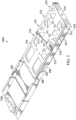
- FIGURE 1 illustrates a perspective view of a chassis 100 for receiving modular information handling resources, in accordance with embodiments of the present invention, with certain elements (e.g., walls for enclosing components within chassis 100) cut-away or removed in order to show information handling resources internal to chassis 100.
- Chassis 100 may be an enclosure that serves as a container for various information handling systems and information handling resources, and may be constructed from steel, aluminum, plastic, and/or any other suitable material. Although the term "chassis" is used, chassis 100 may also be referred to as a case, cabinet, tower, box, enclosure, and/or housing. In certain embodiments, chassis 100 may be configured to hold and/or provide power to a plurality of information handling systems and/or information handling resources.
- chassis 100 may include one or more slots 106 configured to receive drawers 104 for carrying information handling resources, as described in greater detail below.
- some drawers 104 may include one or more information handling systems.
- some drawers 104 may include one or more peripherals (e.g., hard disk drives, graphics processing units, etc.) associated with information handling systems disposed in another drawer 104.
- Each drawer 104 may include an interface connector 118 configured to electrically couple to a midplane 108, thus providing electrical coupling between information handling resources carried on the various drawers 104 to each other and/or one or more networks or devices external to chassis 100.
- Midplane 108 may comprise any system, device, or apparatus configured to interconnect information handling resources of chassis 100 with each other. Accordingly, midplane 108 may include slots, pads, and/or other connectors configured to receive corresponding electrical connectors of information handling resources in order to electrically couple information handling systems disposed in drawers 104 and/or information handling resources to each other.
- a chassis management controller (CMC) 112 may be communicatively coupled to midplane 108 and may comprise any system, device, or apparatus configured to facilitate management and/or control of components of chassis 100, information handling systems modularly coupled within, and/or one or more of its component information handling resources. CMC 112 may be configured to issue commands and/or other signals to manage and/or control information handling systems coupled to slots 106 and/or information handling resources of chassis 100. CMC 112 may comprise a microprocessor, microcontroller, DSP, ASIC, field programmable gate array (“FPGA”), EEPROM, or any combination thereof.
- FPGA field programmable gate array
- CMC 112 may also provide a management console for user/administrator access to these functions.
- CMC 112 may provide for communication with a user interface (e.g., user interface 116), permitting a user to interact with CMC 112 and configure control and management of components of chassis 100 by CMC 112.
- CMC 112 may implement Web Services Management ("WS-MAN") or another suitable management protocol permitting a user to remotely access a CMC 112 to configure chassis 100 and its various information handling resources.
- WS-MAN Web Services Management
- a CMC 112 interfaces with a network interface separate from a traditional network interface of chassis 100, thus allowing for "out-of-band" control of chassis 100, such that communications to and from CMC 112 are communicated via a management channel physically isolated from an "in band” communication channel with the traditional network interface.
- CMC 112 may allow an administrator to remotely manage one or more parameters associated with operation of chassis 100 and its various information handling resources (e.g., power usage, processor allocation, memory allocation, security privileges, etc.).
- One or more air movers 110 may be communicatively coupled to CMC 112, and may include any mechanical or electro-mechanical system, apparatus, or device operable to move air and/or other gasses.
- an air mover 110 may comprise a fan (e.g., a rotating arrangement of vanes or blades which act on the air).
- an air mover 110 may comprise a blower (e.g., a centrifugal fan that employs rotating impellers to accelerate air received at its intake and change the direction of the airflow).
- rotating and other moving components of an air mover 110 may be driven by a motor. The rotational speed of such motor may be controlled by one or more control signals communicated from CMC 112.
- an air mover 110 may cool information handling systems and information handling resources of chassis 100 by drawing cool air into chassis 100 from outside chassis 100, expel warm air from inside chassis 100 to the outside of chassis 100, and/or move air across one or more heatsinks (not explicitly shown) internal to chassis 100 to cool one or more information handling systems and/or information handling resources.
- FIGURE 1 depicts chassis 100 as having two air movers 110, chassis 100 may include any suitable number of air movers 110.
- chassis 100 may include one or more power supplies 114.
- a power supply 114 may include any system, device, or apparatus configured to supply electrical current to one or more information handling resources within chassis 100.
- a user interface 116 may include any system, apparatus, or device via which a user may interact with chassis 100 and its various components by facilitating input from a user allowing the user to manipulate chassis 100 and output to a user allowing chassis 100 to indicate effects of the user's manipulation.
- user interface 116 may include a display suitable for creating graphic images and/or alphanumeric characters recognizable to a user, and may include, for example, a liquid crystal display, a cathode ray tube, a plasma screen, and/or a digital light processor projection monitor.
- a display may be an integral part of chassis 100 and receive power from one or more power supplies 114 of chassis 100, rather than being coupled to chassis 100 via a cable.
- such display may comprise a touch screen device capable of receiving user input
- a touch sensor may be mechanically coupled or overlaid upon the display and may comprise any system, apparatus, or device suitable for detecting the presence and/or location of a tactile touch, including, for example, a resistive sensor, capacitive sensor, surface acoustic wave sensor, projected capacitance sensor, infrared sensor, strain gauge sensor, optical imaging sensor, dispersive signal technology sensor, and/or acoustic pulse recognition sensor.
- user interface 116 may include other user interface elements (e.g., a keypad, buttons, and/or switches placed in proximity to a display) allowing a user to provide input to chassis 100.
- user interface 116 may include one or more visual indicators, such as light-emitting diodes, for example, for communicating information to a user.
- User interface 116 may be coupled to CMC 112 and/or other components of chassis 100, and thus may allow a user to configure various information handling systems and/or information handling resources of chassis 100.
- FIGURES 2 and 3 depict various views of an example chassis drawer 104A for carrying modular information handling resources, in accordance with embodiments of the present invention.
- FIGURE 2 illustrates a perspective view of an example chassis drawer 104A for carrying modular information handling resources, wherein drawer 104A is in an open position drawn from chassis 100, in accordance with embodiments of the present disclosure.
- FIGURE 3 illustrates a perspective view of chassis drawer 104A for carrying modular information handling resources, wherein drawer 104A is in a closed position relative to chassis 100, in accordance with embodiments of the present disclosure.
- chassis drawer 104A may comprise an inner member 204, an intermediate member 206 mechanically coupled to inner member 204, and a carrier member 208 mechanically coupled to intermediate member 206.
- Inner member 204 may be constructed from steel, aluminum, plastic, and/or any other suitable material. Although inner member 204 may have any suitable size and/or shape, inner member 204 is depicted in the embodiments of FIGURES 2 and 3 as having two substantially planar and parallel opposite sides defining a drawer height coupled to each other by a substantially planar bottom generally perpendicular to the sides defining a drawer width and a guide flange extending from and running perpendicular to and along the length of each side such that the flanges project towards each other. In some embodiments, inner member 204 may be mechanically coupled to the internal mechanical structure of chassis 100, such that inner member 204 is fixed relative to chassis 100.
- Intermediate member 206 may be constructed from steel, aluminum, plastic, and/or any other suitable material. Although intermediate member 206 may have any suitable size and/or shape, intermediate member 206 is depicted in the embodiments of FIGURES 2 and 3 as having two generally parallel and planar opposite sides coupled to each other by a substantially planar bottom generally perpendicular to the sides. The height of the sides and the width of the bottom may be such that the corresponding sides and bottom of inner member 204 provide a mechanical guide for intermediate member 206 as chassis drawer 104A is opened and closed. Intermediate member 206 may be mechanically coupled to inner member 204 via bearings and/or other mechanical components such that intermediate member 206 may slide relative to inner member 204 in a direction perpendicular to the drawer height and drawer width defined by inner member 204.
- intermediate member 206 may be limited in the distance it may be drawn from chassis 100 through any combination of suitable structural elements. Similarly, in some embodiments, other mechanical components may restrict motion of intermediate member 206 relative to inner member 204 as chassis drawer 104A is translated from the open position to the closed position.
- Carrier member 208 may be constructed from steel, aluminum, plastic, and/or any other suitable material. Although carrier member 208 may have any suitable size and/or shape, carrier member 208 is depicted in the embodiments of FIGURES 2 and 3 as having a substantially planar top 214 and a substantially planar bottom 216 generally parallel to each other defining a width and depth of carrier member 208, the top 214 and bottom 216 mechanically coupled to each other by one or more structural elements defining a height of carrier member 208, such that top 214 and bottom 216 are generally perpendicular to the sides of intermediate member 206. Carrier member 208 may also include a face 210 mechanically affixed to top 214 and/or bottom 216.
- top 214 may include one or more openings (e.g., above bays 212) allowing for gaseous fluid to pass through.
- bottom 216 may also include one or more openings (e.g., below bays 212) allowing for gaseous fluid to pass through.
- face 210 may be substantially equal in width to the width of carrier member 208 and substantially equal to the height of carrier member 208.
- face 210 may include handles, pull tabs, and/or other features allowing a person to pull on face 210 in order to translate chassis drawer 104A from a closed position to an open position in a direction generally parallel to the depth of top 214 and bottom 216.
- face 210 may include a grill, vent, and/or other opening allowing gaseous fluid to enter and/or exit through face 210.
- each side of carrier member 208 may include a web 230 configured to mechanically couple carrier member 208 to intermediate member 206, as well as openings for a plurality of bays 212.
- Each of the various bays 212 defined by drawer 104A may include one or more electrical components for coupling an information handling resource (e.g., a hard disk drive) inserted into such bay 212 to other information handling resources of chassis 100.
- an information handling resource e.g., a hard disk drive
- a backplane may couple a modular information handling resource disposed in a bay 212 to interface connector 118A, which, as described above, may in turn be coupled to midplane 108.
- the various information handling resources may be coupled to interface connector 118A such that when chassis drawer 104A is drawn open relative to chassis 100, such information handling resources maintain electrical conductivity to interface connector 118A and interface connector 118A may maintain electrical conductivity to midplane 108, thus permitting insertion or removal of an information handling resource without affecting operation of other information handling resources carried by chassis drawer 104A.
- interface connector 118A may only be decoupled from midplane 108 when the entirety of chassis drawer 104A is removed from chassis 100.
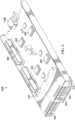
- FIGURE 4 illustrates a perspective view of another example chassis drawer 104B for carrying information handling resources, in accordance with embodiments of the present invention.
- chassis drawer 104B may include one or more mechanical and/or structural elements (e.g., similar or identical to inner member 204, intermediate member 206, and carrier member 208) for translating chassis drawer 104B between open and closed positions relative to chassis 100.
- chassis drawer 104B may be coupled to interface connector 118B such that when chassis drawer 104B is drawn open relative to chassis 100, such information handling resources maintain electrical conductivity to interface connector 118B and interface connector 118B may maintain electrical conductivity to midplane 108, thus permitting insertion or removal of an information handling resource without affecting operation of other information handling resources carried by chassis drawer 104B.
- interface connector 118B may only be decoupled from midplane 108 when the entirety of chassis drawer 104B is removed from chassis 100.
- a backplane 408 may have thereon a plurality (e.g., four) of processors 402 and a chipset associated with each processor 402, thus defining four independent information handling systems carried by chassis drawer 104B.
- Interface connector 118B may also be coupled to backplane 408, thus coupling processors 402 to information handling resources of chassis 100 external to chassis drawer 104B.
- the particular chassis drawer 104B depicted in FIGURE 4 may include a plurality (e.g., four) of hard disk drives 404 communicatively coupled to backplane 408 (and thus one or more of processors 402) via a drive backplane 410.
- chassis drawer 104B may comprise a user interface 412.
- User interface 412 may include any system, apparatus, or device via which a user may interact with compute nodes (e.g., via a remote access controller such as an Integrated Dell Remote Access Controller or "iDRAC" for example) of chassis drawer 104B and its various components by facilitating input from a user allowing the user to compute nodes and to indicate effects of the user's manipulation.
- compute nodes e.g., via a remote access controller such as an Integrated Dell Remote Access Controller or "iDRAC" for example
- user interface 412 may include a display suitable for creating graphic images and/or alphanumeric characters recognizable to a user, and may include, for example, a liquid crystal display, a cathode ray tube, a plasma screen, and/or a digital light processor projection monitor.
- such display may comprise a touch screen device capable of receiving user input, wherein a touch sensor may be mechanically coupled or overlaid upon the display and may comprise any system, apparatus, or device suitable for detecting the presence and/or location of a tactile touch, including, for example, a resistive sensor, capacitive sensor, surface acoustic wave sensor, projected capacitance sensor, infrared sensor, strain gauge sensor, optical imaging sensor, dispersive signal technology sensor, and/or acoustic pulse recognition sensor.
- user interface 412 may include other user interface elements (e.g., a keypad, buttons, and/or switches placed in proximity to a display) allowing a user to provide input to one or more compute nodes of chassis drawer 104B.
- user interface 412 may include one or more visual indicators, such as light-emitting diodes, for example, for communicating information to a user.
- FIGURES 2-4 depict particular example chassis drawers 104
- chassis drawers 104 with other configurations may be employed consistent with the systems and methods herein disclosed.
- a chassis drawer 104 similar to that of chassis drawer 104B may include only one processor, such that the chassis drawer includes one compute node.
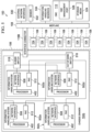
- FIGURE 5 illustrates an example functional block diagram of chassis 100 depicted in FIGURE 1 , wherein chassis 100 has disposed in one of its slots 106 a chassis drawer 104B carrying a plurality of information handling systems 502, in accordance with embodiments of the present invention.
- chassis 100 may include other chassis drawers 104, wherein such chassis drawers 104 may carry information handling systems, hard disk drives, and/or other information handling resources which may or may not be similar to chassis drawers 104A and 104B described above.
- chassis drawer 104B may include a plurality of information handling systems 502 (e.g., 502a-d), each of which may comprise a server or other suitable computing node, an in-band switch 516, an out-of-band switch 518, one or more sensor 532, and one or more other information handling resources 534.
- an information handling system 502 may comprise a processor 402, a network interface 508 communicatively coupled to its associated processor 402, and a remote access controller (RAC) 512.
- RAC remote access controller
- a processor 402 may include any system, device, or apparatus configured to interpret and/or execute program instructions and/or process data, and may include, without limitation, a microprocessor, microcontroller, digital signal processor ("DSP"), application specific integrated circuit (“ASIC”), or any other digital or analog circuitry configured to interpret and/or execute program instructions and/or process data.
- processor 402 may interpret and/or execute program instructions and/or process data stored in a memory or other computer-readable media accessible to processor 402.
- a network interface 508 may comprise any suitable system, apparatus, or device operable to serve as an interface between an associated information handling system 502 and a private communication network internal to chassis drawer 104B formed by information handling systems 502 and in-band switch 516.
- Network interface 508 may enable an associated information handling system 502 to communicate using any suitable transmission protocol and/or standard.
- network interface 508 may comprise one or more network interface cards, or "NICs.”
- network interface 508 may comprise one or more local area network (LAN)-on-motherboard (LOM) devices.
- LAN local area network
- LOM local area network
- network interface 508 may include a plurality of NICs, LOMs, or other network interface devices, in order to provide communication redundancy or robustness.
- a RAC 512 may be implemented by, for example, a microprocessor, microcontroller, DSP, ASIC, EEPROM, or any combination thereof. RAC 512 may be configured to communicate with CMC 112. Such communication may be made, for example, via private management network fabric implemented using out-of-band switch 518. RAC 512 may be configured to provide out-of-band management facilities for management of an associated information handling system 502. Such management may be made by CMC 112 even if information handling system 502 is powered off or powered to a standby state.
- a RAC 512 may include a processor, memory, and network connection separate from the rest of its associated information handling system 502.
- a RAC 502 may include or may be an integral part of a baseboard management controller (BMC), Dell Remote Access Controller (DRAC) or an Integrated Dell Remote Access Controller (iDRAC).
- BMC baseboard management controller
- DRAC Dell Remote Access Controller
- iDRAC Integrated Dell Remote Access Controller
- In-band switch 516 may comprise any system, device, or apparatus configured to couple network interfaces 508 of information handling systems 502 to external network interface 530 and perform switching between network interfaces 508 and an external communication network communicatively coupled to external network interface 530 based on a network configuration of various ports (not explicitly shown) of network interfaces 508, in-band switch 516, and external network interface 530, as described in greater detail below.
- In-band switch 516 may comprise a PCIe switch, a generalized PC bus switch, an Infiniband switch, or other suitable switch.
- out-of-band switch 518 may comprise any system, device, or apparatus configured to couple RACs 512 of information handling systems 502 to CMC 112 and perform switching between RACs 512 and CMC 112 in order to provide for centralized management of individual information handling systems 502 via a management console coupled to CMC 112 (e.g., via CMC management port 528).
- an external network interface 530 may be communicatively coupled to midplane 108.
- External network interface 530 may comprise any suitable system, apparatus, or device operable to serve as an interface between chassis 100 and a network external to chassis 100.
- External network interface 530 may enable an information handling system 502 to communicate with such external network using any suitable transmission protocol and/or standard.
- external network interface 530 may comprise one or more network interface cards, or "NICs.”
- NICs network interface cards
- external network interface 530 may comprise one or more input/output module (IOM) devices.
- IOM input/output module
- external network interface 530 may include a plurality of NICs, IOMs, or other network interface devices, in order to provide communication redundancy or robustness.
- CMC 112 may include storage media 524 and a CMC management port 528.
- Storage media 524 may include any system, device, or apparatus configured to retain program instructions and/or data for a period of time (e.g., computer-readable media).
- Storage media 524 may include RAM, EEPROM, a PCMCIA card, flash memory, magnetic storage, opto-magnetic storage, or any suitable selection and/or array of volatile or non-volatile memory that retains data after power to CMC 112 is turned off .
- CMC management port 528 serves as a network interface between CMC 112 and a remote management console configured to allow a user to remotely manage components of chassis 100 via an out-of-band network physically isolated from an in-band network coupled to external network interface 530.
- CMC management port 528 may communicate with such remote management console via any suitable management protocol or standard, including without limitation Intelligent Platform Management Interface (IPMI) and Simple Network Management Protocol (SNMP).
- IPMI Intelligent Platform Management Interface
- SNMP Simple Network Management Protocol
- Sensor 532 may be coupled to midplane 108 and may include any suitable system, device, or apparatus that measures a physical quantity and converts it into a signal which can be read by a processor 402, RAC 512, and/or CMC 112.
- a sensor 532 may include a temperature sensor (e.g., thermocouple, thermistor, thermostat, etc.), a speed sensor (e.g., a Hall effect sensor used to determine rotational speed of an air mover (e.g., an air mover 110), or any other suitable sensor for detecting a physical quantity associated with chassis 100 or a component thereof. Based on a measured physical quantity of a sensor 532, an information handling system 502 or a component thereof may take an action.
- a temperature sensor e.g., thermocouple, thermistor, thermostat, etc.
- a speed sensor e.g., a Hall effect sensor used to determine rotational speed of an air mover (e.g., an air mover 110)
- an information handling system 502 may take corrective or remedial action in response to a sensed temperature exceeding a threshold, such as causing an increase in speed of an air mover 110, reducing power consumption of an information handling system 502, and/or other remedial action.
- a chassis 100 may include any number of any combination of types of sensors 532.
- One or more information handling resources 534 may be communicatively coupled to midplane 108 or otherwise disposed in chassis 100 and may include one or more processors, service processors, basic input/output systems, buses, memories, I/O devices and/or interfaces, storage resources, network interfaces, motherboards, air movers, power supplies, and/or any other components and/or elements suitable for use in an information handling system. Such information handling resources 534 may also include air movers 110 and power supply 114 depicted in FIGURE 1 but not otherwise depicted in FIGURE 5 . As is known in the art, some information handling resources 534 may operate in accordance with firmware instructions stored on a computer-readable medium integral to or otherwise accessible to the information handling resource.
- RACs include computer-readable media for storing data and instructions locally to the RAC (e.g., via a flash or secure digital (SD) card).
- SD secure digital
- FIGURE 6 illustrates a flow chart of an example method 600 for monitoring chassis-level sensors 532, in accordance with embodiments of the present invention.
- method 600 may begin at step 602.
- teachings of the present disclosure may be implemented in a variety of configurations of chassis 100.
- the preferred initialization point for method 600 and the order of the steps comprising method 600 may depend on the implementation chosen.
- CMC 112 monitors one or more sensors 532 by receiving signals from the one or more sensors 532 indicative of the physical quantities measured by such sensors 532.
- CMC 112 may determine if a measured physical quantity of a sensor 532 has changed by more than a threshold amount. For example, for a temperature sensor, such threshold amount may be equal to five degrees Celsius. If such a change has occurred, method 600 may proceed to step 606. Otherwise, step 604 may repeat until such a change has occurred.
- CMC 112 may communicate to a RAC 512 (e.g., via out-of-bound switch 518) present on a chassis drawer 104 disposed in chassis 100 an indication that such a change has occurred.
- a RAC 512 e.g., via out-of-bound switch 5128 present on a chassis drawer 104 disposed in chassis 100 an indication that such a change has occurred.
- Such indication may include an IPMI over LAN command or other suitable command communicated between CMC 112 and RAC 512 via out-of-band switch 518.
- RAC 512 may communicate a request to CMC 112 to retrieve (e.g., download) sensor information from CMC 112 and may receive the sensor information from CMC 112. Such download may be performed using trivial file transfer protocol (TFTP), IPMI over LAN, or other suitable protocol or standard for file transfer.
- TFTP trivial file transfer protocol
- RAC 512 may, alone or in concert with an associated processor 402, process the sensor information in order to model performance of chassis 100 components, initiate responsive action to a measured physical quantity, and/or perform any other action. Accordingly, a RAC 512 may model chassis 100 components in the same fashion as it would in a rack server.
- CMC 112 serves as a proxy between sensors 532 and RAC 512.
- FIGURE 6 discloses a particular number of steps to be taken with respect to method 600, method 600 may be executed with greater or fewer steps than those depicted in FIGURE 6 .
- FIGURE 6 discloses a certain order of steps to be taken with respect to method 600, the steps comprising method 600 may be completed in any suitable order.
- Method 600 may be implemented using CMC 112, a remote access controller 512, and/or any other system operable to implement method 600.
- method 600 may be implemented partially or fully in software and/or firmware embodied in computer-readable media and executable on a processor or controller.
- FIGURE 7 illustrates a flow chart of an example method 700 for management of chassis-level information handling resources 534, in accordance with examples embodimenfeo of the present disclosure.
- method 700 may begin at step 702.
- teachings of the present disclosure may be implemented in a variety of configurations of chassis 100. As such, the preferred initialization point for method 700 and the order of the steps comprising method 700 may depend on the implementation chosen.
- a user may upload to RAC 512 a firmware image for a chassis-level information handling resource 534.
- firmware image may include updated firmware for such information handling resource 534.
- a user may upload the firmware image to RAC 512 in any suitable manner, including without limitation, by issuing proper commands via user interface 116 or a keyboard-video-mouse interface (not explicitly shown) coupled to chassis 100 or a chassis drawer 104 including such RAC 512.
- Such file may be uploaded from a readily-removable computer-readable medium (e.g., flash drive, secure digital (SD) card, etc.), communicatively coupled to RAC 512 via a suitable external media interface (e.g., Universal Serial Bus port, SE port) of chassis 100 or a chassis drawer 104 including such RAC 512 (not explicitly shown).
- a suitable external media interface e.g., Universal Serial Bus port, SE port
- the user may also provide an indication regarding to which information handling resource 534 the firmware image is to be applied.
- the firmware image itself, or metadata associated therewith may indicate to which information handling resource 534 the firmware image is to be applied.
- RAC 512 may communicate to a CMC 112 (e.g., via out-of-bound switch 518) an indication that such a firmware update is to be applied to one or more information handling resources 534.
- Such indication may include an IPMI over LAN command or other suitable command communicated between RAC 512 and CMC 112 via out-of-band switch 518.
- CMC 112 may retrieve the firmware image from RAC 512. Such transfer may be performed using trivial file transfer protocol (TFTP), IPMI over LAN, or other suitable protocol or standard for file transfer.
- TFTP trivial file transfer protocol
- IPMI IPMI over LAN
- CMC 112 may perform the firmware update by applying the firmware image to the appropriate information handling resource 534.
- CMC 112 may, from time-to-time communicate an indication to RAC 512 regarding the status of the update.
- Such indication may include an IPMI over LAN command or other suitable command communicated between RAC 512 and CMC 112 via out-of-band switch 518.
- a RAC 512 may perform firmware updates and manage chassis 100 components in the same fashion as it would in a rack server, with CMC 112 serving as an intermediary between information handling resources 534 and RAC 512.
- FIGURE 7 discloses a particular number of steps to be taken with respect to method 700, method 700 may be executed with greater or fewer steps than those depicted in FIGURE 7 .
- FIGURE 7 discloses a certain order of steps to be taken with respect to method 700, the steps comprising method 700 may be completed in any suitable order.
- Method 700 may be implemented using CMC 112, a remote access controller 512, and/or any other system operable to implement method 700.
- method 700 may be implemented partially or fully in software and/or firmware embodied in computer-readable media and executable on a processor or controller.
- FIGURE 8 illustrates a flow chart of an example method 800 for allocation of storage media 524 associated with CMC 112 to a RAC 512, in accordance with examples of the present disclosure.
- method 800 may begin at step 802.
- teachings of the present disclosure may be implemented in a variety of configurations of chassis 100. As such, the preferred initialization point for method 800 and the order of the steps comprising method 800 may depend on the implementation chosen.
- a RAC 512 may determine if storage local to RAC 512 (e.g., within the chassis drawer 104 comprising the RAC 512) is present and available. If local storage is not available, method 800 may proceed to step 804. Otherwise, method 800 may end.
- RAC 512 may send a request to CMC 112 (e.g., via out-of-band switch 518) to allocate a portion of storage media 524 as storage for RAC 512.
- request may include an IPMI over LAN command or other suitable command communicated between RAC 512 and CMC 112 via out-of-band switch 518.
- CMC 112 may determine if a portion of storage media 524 is available responsive to the request from RAC 512. If a portion of storage media 524 is available, method 800 may proceed to step 808. Otherwise, method 800 may end.
- CMC 112 may allocate a portion of storage within storage media 524 to RAC 512.
- CMC 112 may create a share (e.g., a Network File System (NFS) share) comprising the allocated portion.
- CMC 112 may communicate the share name or other identifying information for the created share to RAC 512. Such communication may include an IPMI over LAN command or other suitable command communicated between CMC 112 and RAC 512 via out-of-band switch 518.
- NFS Network File System
- RAC 512 may mount the share as a logical storage medium of RAC 512. Accordingly, should RAC 512 require file storage I/O, it may issue the appropriate I/O commands to the mounted share, and a portion of storage media 524 may serve as virtual storage for RAC 512.
- portions of storage media 524 may also be allocated for a plurality of RACs 512 present in chassis 100 using methods similar to those described with respect to method 800.
- FIGURE 8 discloses a particular number of steps to be taken with respect to method 800, method 800 may be executed with greater or fewer steps than those depicted in FIGURE 8 .
- FIGURE 8 discloses a certain order of steps to be taken with respect to method 800, the steps comprising method 800 may be completed in any suitable order.
- Method 800 may be implemented using CMC 112, a remote access controller 512, and/or any other system operable to implement method 800.
- method 800 may be implemented partially or fully in software and/or firmware embodied in computer-readable media and executable on a processor or controller.
Landscapes
- Engineering & Computer Science (AREA)
- Theoretical Computer Science (AREA)
- General Engineering & Computer Science (AREA)
- Physics & Mathematics (AREA)
- General Physics & Mathematics (AREA)
- Computer Hardware Design (AREA)
- Human Computer Interaction (AREA)
- Thermal Sciences (AREA)
- Microelectronics & Electronic Packaging (AREA)
- Automation & Control Theory (AREA)
- Debugging And Monitoring (AREA)
- Information Transfer Between Computers (AREA)
- Computer And Data Communications (AREA)
Claims (5)
- Procédé de fourniture d'une console de gestion à un utilisateur ou à un administrateur, comprenant, dans un châssis (100) présentant une pluralité de fentes (106), chacune étant configurée pour recevoir un module (104) présentant un ou plusieurs systèmes de gestion d'informations (502) dans lequel chaque fente (106) est configurée pour coupler électriquement et de manière communicative le module (104) à d'autres composants du châssis (100) :la réception, par un dispositif de commande de gestion de châssis (112) intégré au châssis (100), d'un signal provenant d'un capteur (532) intégré au châssis (100), du signal indiquant une grandeur physique mesurée par le capteur (532) ; caractérisé parla communication, en provenance du dispositif de commande de gestion de châssis (112) et à destination d'un dispositif de commande d'accès à distance (512) intégré à au moins un module (104) disposé dans la pluralité de fentes (106), d'informations de capteur conformes au signal, dans lequel le dispositif de commande de gestion de châssis (112) est configuré pour servir de proxy entre le capteur (532) et le dispositif de commande d'accès à distance (512), dans lequel le dispositif de commande de gestion de châssis (112) interagit avec une interface réseau distincte d'une interface réseau du châssis (100), ce qui permet une commande hors bande du châssis (100) de telle sorte que les communications à destination et en provenance du dispositif de commande de gestion de châssis (112) soient communiquées par l'intermédiaire d'un canal de gestion physiquement isolé d'un canal de communication en bande avec l'interface réseau du châssis (100).
- Procédé selon la revendication 1, comprenant également :la détermination, par le dispositif de commande de gestion de châssis (112), du fait de savoir si la grandeur physique mesurée a changé d'au moins une quantité seuil en fonction du signal ; eten réponse à une détermination du changement de la grandeur physique mesurée d'au moins la quantité seuil, la communication à destination du dispositif de commande d'accès à distance (512) d'une indication du changement de la grandeur physique mesurée.
- Procédé selon la revendication 2, comprenant également la réception d'une requête au niveau du dispositif de commande de gestion de châssis (112) en provenance du dispositif de commande d'accès à distance (512) pour communiquer les informations de capteur au dispositif de commande d'accès à distance (512), dans lequel la requête est envoyée par le dispositif de commande d'accès à distance (512) en réponse à l'indication et également dans lequel la communication des informations de capteur est réalisée en réponse à la réception de la requête.
- Procédé selon la revendication 1, dans lequel le dispositif de gestion de châssis (112) et le dispositif de commande d'accès à distance (512) sont couplés de manière communicative par l'intermédiaire d'un réseau privé interne intégré au châssis (100).
- Châssis (100) présentant une pluralité de fentes (106), chacune étant configurée pour recevoir un module (104) présentant un ou plusieurs systèmes de gestion d'informations (502), dans lequel chaque fente (106) est configurée pour coupler électriquement et de manière communicative le module (104) à d'autres composants du châssis (100), ledit châssis (100) comprenant un dispositif de commande de gestion de châssis (112) intégré au châssis (100), un capteur (532) intégré au châssis (100), et une interface réseau (508),le châssis (100) présentant un module (104) disposé dans l'une de la pluralité de fentes (106), le module (104) présentant un ou plusieurs systèmes de traitement d'informations, le module (104) comprenant un dispositif de commande d'accès à distance (512) intégré au module (104),le dispositif de commande de gestion de châssis (112) étant configuré pour servir de proxy entre le capteur (532) et le dispositif de commande d'accès à distance (512),le dispositif de commande de gestion de châssis (112) comprenant un port de gestion (528) configuré pour servir d'interface réseau entre le dispositif de commande de gestion de châssis (112) et une console de gestion à distance,le châssis étant configuré pour exécuter le procédé selon l'une quelconque des revendications 1 à 4.
Applications Claiming Priority (2)
| Application Number | Priority Date | Filing Date | Title |
|---|---|---|---|
| US14/097,784 US20150160627A1 (en) | 2013-12-05 | 2013-12-05 | Methods and systems for monitoring and management in a distributed architecture information handling system chassis |
| PCT/US2014/014130 WO2015084418A1 (fr) | 2013-12-05 | 2014-01-31 | Procédés et systèmes de surveillance et de gestion dans un bâti de système de gestion d'informations à architecture distribuée |
Publications (3)
| Publication Number | Publication Date |
|---|---|
| EP3077886A1 EP3077886A1 (fr) | 2016-10-12 |
| EP3077886A4 EP3077886A4 (fr) | 2018-01-24 |
| EP3077886B1 true EP3077886B1 (fr) | 2024-12-04 |
Family
ID=53271086
Family Applications (1)
| Application Number | Title | Priority Date | Filing Date |
|---|---|---|---|
| EP14867589.5A Active EP3077886B1 (fr) | 2013-12-05 | 2014-01-31 | Procédés et systèmes de surveillance et de gestion dans un bâti de système de gestion d'informations à architecture distribuée |
Country Status (4)
| Country | Link |
|---|---|
| US (1) | US20150160627A1 (fr) |
| EP (1) | EP3077886B1 (fr) |
| CN (2) | CN105814508B (fr) |
| WO (1) | WO2015084418A1 (fr) |
Families Citing this family (12)
| Publication number | Priority date | Publication date | Assignee | Title |
|---|---|---|---|---|
| US10270652B2 (en) * | 2012-04-25 | 2019-04-23 | Hewlett Packard Enterprise Development Lp | Network management |
| TWI582585B (zh) * | 2015-11-18 | 2017-05-11 | 神雲科技股份有限公司 | 機櫃的監控系統 |
| TWI614596B (zh) * | 2016-12-07 | 2018-02-11 | 英業達股份有限公司 | 電子裝置 |
| US10728086B2 (en) * | 2017-03-23 | 2020-07-28 | Dell Products, L.P. | System and method for providing a redundant communication path between a server rack controller and one or more server controllers |
| US10649792B1 (en) | 2018-02-09 | 2020-05-12 | American Megatrends International, Llc | Cloning of firmware configuration settings using rest over IPMI interface |
| US10409584B1 (en) | 2018-02-09 | 2019-09-10 | American Megatrends International, Llc | Peripheral device firmware update using rest over IPMI interface firmware update module |
| US10572242B1 (en) * | 2018-02-09 | 2020-02-25 | American Megatrends International, Llc | Firmware update using rest over IPMI interface |
| US10628176B1 (en) | 2018-02-09 | 2020-04-21 | American Megatrends International, Llc | Firmware configuration using REST over IPMI interface |
| US10489142B1 (en) | 2018-02-09 | 2019-11-26 | American Megatrends International, Llc | Secure firmware integrity monitoring using rest over IPMI interface |
| US10416988B1 (en) | 2018-02-09 | 2019-09-17 | American Megatrends International, Llc | Peripheral device firmware update using rest over IPMI interface firmware shell utility |
| US10776286B1 (en) | 2018-02-09 | 2020-09-15 | American Megatrends International, Llc | Rest over IPMI interface for firmware to BMC communication |
| US12399699B2 (en) * | 2022-09-23 | 2025-08-26 | Dell Products, L.P. | Systems and methods for performing health score-based firmware updates |
Family Cites Families (32)
| Publication number | Priority date | Publication date | Assignee | Title |
|---|---|---|---|---|
| US6809637B1 (en) * | 1999-09-03 | 2004-10-26 | The Goodyear Tire & Rubber Company | Monitoring a condition of a pneumatic tire |
| US6640272B1 (en) * | 2000-08-31 | 2003-10-28 | Hewlett-Packard Development Company, L.P. | Automated backplane cable connection identification system and method |
| US7272795B2 (en) * | 2003-06-27 | 2007-09-18 | Microsoft Corporation | Micro-monitor to monitor database environments |
| US7483974B2 (en) * | 2003-09-24 | 2009-01-27 | Intel Corporation | Virtual management controller to coordinate processing blade management in a blade server environment |
| US7240225B2 (en) * | 2003-11-10 | 2007-07-03 | Dell Products L.P. | System and method for throttling power in one or more information handling systems |
| US7873693B1 (en) * | 2004-02-13 | 2011-01-18 | Habanero Holdings, Inc. | Multi-chassis fabric-backplane enterprise servers |
| US7398401B2 (en) | 2004-03-25 | 2008-07-08 | Intel Corporation | Method and apparatus for communicating information from an operating system based environment of a server blade to the chassis management module |
| US20060193250A1 (en) * | 2005-02-28 | 2006-08-31 | Tekelec | Methods, systems and computer program products for thermal management of a processor associated with a network interface |
| US7676666B2 (en) * | 2006-02-02 | 2010-03-09 | Dell Products L.P. | Virtual BIOS firmware hub |
| US7555666B2 (en) * | 2006-05-04 | 2009-06-30 | Dell Products L.P. | Power profiling application for managing power allocation in an information handling system |
| US7669071B2 (en) * | 2006-05-05 | 2010-02-23 | Dell Products L.P. | Power allocation management in an information handling system |
| US7500078B2 (en) * | 2006-08-25 | 2009-03-03 | Dell Products L.P. | Thermal control of memory modules using proximity information |
| US20080304229A1 (en) * | 2007-06-07 | 2008-12-11 | International Business Machines Corporation | Air-pressure-dependent control of cooling systems using a shared air pressure sensor |
| US8639464B2 (en) * | 2008-01-18 | 2014-01-28 | Dresser, Inc. | Flow meter diagnostic processing |
| US8020167B2 (en) * | 2008-05-05 | 2011-09-13 | Dell Products L.P. | System and method for automatic throttling of resources in an information handling system chassis |
| US7984311B2 (en) * | 2008-08-08 | 2011-07-19 | Dell Products L.P. | Demand based power allocation |
| CN101938368A (zh) * | 2009-06-30 | 2011-01-05 | 国际商业机器公司 | 刀片服务器系统中的虚拟机管理器和虚拟机处理方法 |
| US8848712B2 (en) * | 2009-08-10 | 2014-09-30 | Infinera Corporation | Distributed RSVP-TE in a multi-chassis node architecture |
| JP4660621B1 (ja) * | 2009-10-29 | 2011-03-30 | 株式会社東芝 | 情報処理装置およびメモリ制御方法 |
| KR101823696B1 (ko) * | 2010-05-21 | 2018-01-30 | 에드워즈 가부시키가이샤 | 배기 펌프의 퇴적물 검지 장치와, 그 장치를 구비한 배기 펌프 |
| US8838286B2 (en) * | 2010-11-04 | 2014-09-16 | Dell Products L.P. | Rack-level modular server and storage framework |
| US9098257B2 (en) * | 2011-02-03 | 2015-08-04 | Dell Products L.P. | Information handling system server architecture for improved management communication |
| US8773999B2 (en) * | 2011-10-26 | 2014-07-08 | International Business Machines Corporation | Distributed chassis architecture having integrated service appliances |
| SG11201500570WA (en) * | 2012-07-31 | 2015-04-29 | Carrier Corp | Frozen evaporator coil detection and defrost initiation |
| US9092583B2 (en) * | 2012-11-16 | 2015-07-28 | Dell Products L.P. | Systems and methods for communication between modular information handling systems in a chassis |
| US9268730B2 (en) * | 2013-02-28 | 2016-02-23 | Oracle International Corporation | Computing rack-based virtual backplane for field replaceable units |
| US9256565B2 (en) * | 2013-02-28 | 2016-02-09 | Oracle International Corporation | Central out of band management of field replaceable united of computing rack |
| US9261922B2 (en) * | 2013-02-28 | 2016-02-16 | Oracle International Corporation | Harness for implementing a virtual backplane in a computing rack for field replaceable units |
| US9535482B2 (en) * | 2013-03-05 | 2017-01-03 | Ixia | Methods, systems, and computer readable media for controlling processor card power consumption in a network test equipment chassis that includes a plurality of processor cards |
| US9219645B2 (en) * | 2013-03-12 | 2015-12-22 | Dell Products L.P. | Systems and methods for sharing a single firmware image in a chassis configured to receive a plurality of modular information handling systems |
| CN103395064B (zh) * | 2013-07-30 | 2015-09-30 | 武汉大学 | 一种基于超声导波技术的排管检测机器人 |
| US9152593B2 (en) * | 2013-09-06 | 2015-10-06 | Cisco Technology, Inc. | Universal PCI express port |
-
2013
- 2013-12-05 US US14/097,784 patent/US20150160627A1/en not_active Abandoned
-
2014
- 2014-01-31 CN CN201480066331.3A patent/CN105814508B/zh active Active
- 2014-01-31 WO PCT/US2014/014130 patent/WO2015084418A1/fr not_active Ceased
- 2014-01-31 CN CN201810845648.7A patent/CN109283986B/zh active Active
- 2014-01-31 EP EP14867589.5A patent/EP3077886B1/fr active Active
Also Published As
| Publication number | Publication date |
|---|---|
| EP3077886A1 (fr) | 2016-10-12 |
| WO2015084418A1 (fr) | 2015-06-11 |
| CN105814508A (zh) | 2016-07-27 |
| CN109283986A (zh) | 2019-01-29 |
| US20150160627A1 (en) | 2015-06-11 |
| CN105814508B (zh) | 2019-11-15 |
| EP3077886A4 (fr) | 2018-01-24 |
| CN109283986B (zh) | 2022-04-19 |
Similar Documents
| Publication | Publication Date | Title |
|---|---|---|
| EP3077886B1 (fr) | Procédés et systèmes de surveillance et de gestion dans un bâti de système de gestion d'informations à architecture distribuée | |
| EP3080954B1 (fr) | Configuration de commutateur de réseau pour composant modulaire | |
| US9401078B2 (en) | Systems and methods for muting visual indicators in an information handling system | |
| US9471126B2 (en) | Power management for PCIE switches and devices in a multi-root input-output virtualization blade chassis | |
| US10430351B2 (en) | Systems and methods for virtual service processor data bridging | |
| US10082848B2 (en) | Systems and methods for thermal adaptation for virtual thermal inputs in a chassis infrastructure | |
| US9836309B2 (en) | Systems and methods for in-situ fabric link optimization in a modular information handling system chassis | |
| US10353453B2 (en) | Methods and systems for multiple module power regulation in a modular chassis | |
| US10126798B2 (en) | Systems and methods for autonomously adapting powering budgeting in a multi-information handling system passive chassis environment | |
| US9772652B2 (en) | Systems and methods for distributing and synchronizing real-time clock | |
| US9258913B2 (en) | Multi-stage information handling resource release latch for use in a modular information handling system chassis | |
| US10642672B2 (en) | Systems and methods for dynamic thermal excursion timeout determination and predictive failure notification based on airflow escape detection | |
| US20140149658A1 (en) | Systems and methods for multipath input/output configuration | |
| US10405461B2 (en) | Systems and methods for fan performance-based scaling of thermal control parameters | |
| US10430251B2 (en) | Systems and methods for load balancing based on thermal parameters | |
| US10069682B2 (en) | Systems and methods for proactively recommending input/output redirection using management controller | |
| US8935555B2 (en) | Wake-on-local-area-network operations in a modular chassis using a virtualized input-output-virtualization environment | |
| US11910558B2 (en) | Chassis management controller monitored overcurrent protection for modular information handling systems | |
| US10437303B2 (en) | Systems and methods for chassis-level view of information handling system power capping | |
| US9740650B2 (en) | Methods and systems for associating peripheral information handling resources to compute nodes in a modular information system chassis | |
| US9148339B2 (en) | Methods and systems for deploying network configuration information for multiple information handling systems | |
| US20150170484A1 (en) | Systems and methods for sensing and identifying information handling resources in a disaggregated server |
Legal Events
| Date | Code | Title | Description |
|---|---|---|---|
| PUAI | Public reference made under article 153(3) epc to a published international application that has entered the european phase |
Free format text: ORIGINAL CODE: 0009012 |
|
| 17P | Request for examination filed |
Effective date: 20160628 |
|
| AK | Designated contracting states |
Kind code of ref document: A1 Designated state(s): AL AT BE BG CH CY CZ DE DK EE ES FI FR GB GR HR HU IE IS IT LI LT LU LV MC MK MT NL NO PL PT RO RS SE SI SK SM TR |
|
| AX | Request for extension of the european patent |
Extension state: BA ME |
|
| DAX | Request for extension of the european patent (deleted) | ||
| RIC1 | Information provided on ipc code assigned before grant |
Ipc: G06F 1/20 20060101AFI20170720BHEP Ipc: G06F 9/445 20060101ALI20170720BHEP Ipc: H05K 7/20 20060101ALI20170720BHEP |
|
| A4 | Supplementary search report drawn up and despatched |
Effective date: 20171221 |
|
| RIC1 | Information provided on ipc code assigned before grant |
Ipc: G06F 1/20 20060101AFI20171215BHEP Ipc: G06F 9/445 20180101ALI20171215BHEP Ipc: H05K 7/20 20060101ALI20171215BHEP |
|
| STAA | Information on the status of an ep patent application or granted ep patent |
Free format text: STATUS: EXAMINATION IS IN PROGRESS |
|
| 17Q | First examination report despatched |
Effective date: 20200701 |
|
| GRAP | Despatch of communication of intention to grant a patent |
Free format text: ORIGINAL CODE: EPIDOSNIGR1 |
|
| STAA | Information on the status of an ep patent application or granted ep patent |
Free format text: STATUS: GRANT OF PATENT IS INTENDED |
|
| INTG | Intention to grant announced |
Effective date: 20240808 |
|
| P01 | Opt-out of the competence of the unified patent court (upc) registered |
Free format text: CASE NUMBER: APP_50809/2024 Effective date: 20240909 |
|
| GRAS | Grant fee paid |
Free format text: ORIGINAL CODE: EPIDOSNIGR3 |
|
| GRAA | (expected) grant |
Free format text: ORIGINAL CODE: 0009210 |
|
| STAA | Information on the status of an ep patent application or granted ep patent |
Free format text: STATUS: THE PATENT HAS BEEN GRANTED |
|
| AK | Designated contracting states |
Kind code of ref document: B1 Designated state(s): AL AT BE BG CH CY CZ DE DK EE ES FI FR GB GR HR HU IE IS IT LI LT LU LV MC MK MT NL NO PL PT RO RS SE SI SK SM TR |
|
| REG | Reference to a national code |
Ref country code: GB Ref legal event code: FG4D |
|
| REG | Reference to a national code |
Ref country code: CH Ref legal event code: EP |
|
| REG | Reference to a national code |
Ref country code: DE Ref legal event code: R096 Ref document number: 602014091290 Country of ref document: DE |
|
| REG | Reference to a national code |
Ref country code: IE Ref legal event code: FG4D |
|
| REG | Reference to a national code |
Ref country code: LT Ref legal event code: MG9D |
|
| REG | Reference to a national code |
Ref country code: NL Ref legal event code: MP Effective date: 20241204 |
|
| PG25 | Lapsed in a contracting state [announced via postgrant information from national office to epo] |
Ref country code: HR Free format text: LAPSE BECAUSE OF FAILURE TO SUBMIT A TRANSLATION OF THE DESCRIPTION OR TO PAY THE FEE WITHIN THE PRESCRIBED TIME-LIMIT Effective date: 20241204 |
|
| PG25 | Lapsed in a contracting state [announced via postgrant information from national office to epo] |
Ref country code: FI Free format text: LAPSE BECAUSE OF FAILURE TO SUBMIT A TRANSLATION OF THE DESCRIPTION OR TO PAY THE FEE WITHIN THE PRESCRIBED TIME-LIMIT Effective date: 20241204 |
|
| PG25 | Lapsed in a contracting state [announced via postgrant information from national office to epo] |
Ref country code: BG Free format text: LAPSE BECAUSE OF FAILURE TO SUBMIT A TRANSLATION OF THE DESCRIPTION OR TO PAY THE FEE WITHIN THE PRESCRIBED TIME-LIMIT Effective date: 20241204 |
|
| PG25 | Lapsed in a contracting state [announced via postgrant information from national office to epo] |
Ref country code: ES Free format text: LAPSE BECAUSE OF FAILURE TO SUBMIT A TRANSLATION OF THE DESCRIPTION OR TO PAY THE FEE WITHIN THE PRESCRIBED TIME-LIMIT Effective date: 20241204 |
|
| PG25 | Lapsed in a contracting state [announced via postgrant information from national office to epo] |
Ref country code: NO Free format text: LAPSE BECAUSE OF FAILURE TO SUBMIT A TRANSLATION OF THE DESCRIPTION OR TO PAY THE FEE WITHIN THE PRESCRIBED TIME-LIMIT Effective date: 20250304 |
|
| PG25 | Lapsed in a contracting state [announced via postgrant information from national office to epo] |
Ref country code: LV Free format text: LAPSE BECAUSE OF FAILURE TO SUBMIT A TRANSLATION OF THE DESCRIPTION OR TO PAY THE FEE WITHIN THE PRESCRIBED TIME-LIMIT Effective date: 20241204 Ref country code: GR Free format text: LAPSE BECAUSE OF FAILURE TO SUBMIT A TRANSLATION OF THE DESCRIPTION OR TO PAY THE FEE WITHIN THE PRESCRIBED TIME-LIMIT Effective date: 20250305 |
|
| PG25 | Lapsed in a contracting state [announced via postgrant information from national office to epo] |
Ref country code: RS Free format text: LAPSE BECAUSE OF FAILURE TO SUBMIT A TRANSLATION OF THE DESCRIPTION OR TO PAY THE FEE WITHIN THE PRESCRIBED TIME-LIMIT Effective date: 20250304 |
|
| PG25 | Lapsed in a contracting state [announced via postgrant information from national office to epo] |
Ref country code: NL Free format text: LAPSE BECAUSE OF FAILURE TO SUBMIT A TRANSLATION OF THE DESCRIPTION OR TO PAY THE FEE WITHIN THE PRESCRIBED TIME-LIMIT Effective date: 20241204 |
|
| REG | Reference to a national code |
Ref country code: AT Ref legal event code: MK05 Ref document number: 1748830 Country of ref document: AT Kind code of ref document: T Effective date: 20241204 |
|
| PG25 | Lapsed in a contracting state [announced via postgrant information from national office to epo] |
Ref country code: SM Free format text: LAPSE BECAUSE OF FAILURE TO SUBMIT A TRANSLATION OF THE DESCRIPTION OR TO PAY THE FEE WITHIN THE PRESCRIBED TIME-LIMIT Effective date: 20241204 |
|
| PG25 | Lapsed in a contracting state [announced via postgrant information from national office to epo] |
Ref country code: PL Free format text: LAPSE BECAUSE OF FAILURE TO SUBMIT A TRANSLATION OF THE DESCRIPTION OR TO PAY THE FEE WITHIN THE PRESCRIBED TIME-LIMIT Effective date: 20241204 |
|
| PG25 | Lapsed in a contracting state [announced via postgrant information from national office to epo] |
Ref country code: IS Free format text: LAPSE BECAUSE OF FAILURE TO SUBMIT A TRANSLATION OF THE DESCRIPTION OR TO PAY THE FEE WITHIN THE PRESCRIBED TIME-LIMIT Effective date: 20250404 |
|
| PG25 | Lapsed in a contracting state [announced via postgrant information from national office to epo] |
Ref country code: PT Free format text: LAPSE BECAUSE OF FAILURE TO SUBMIT A TRANSLATION OF THE DESCRIPTION OR TO PAY THE FEE WITHIN THE PRESCRIBED TIME-LIMIT Effective date: 20250404 |
|
| PG25 | Lapsed in a contracting state [announced via postgrant information from national office to epo] |
Ref country code: EE Free format text: LAPSE BECAUSE OF FAILURE TO SUBMIT A TRANSLATION OF THE DESCRIPTION OR TO PAY THE FEE WITHIN THE PRESCRIBED TIME-LIMIT Effective date: 20241204 |
|
| PG25 | Lapsed in a contracting state [announced via postgrant information from national office to epo] |
Ref country code: AT Free format text: LAPSE BECAUSE OF FAILURE TO SUBMIT A TRANSLATION OF THE DESCRIPTION OR TO PAY THE FEE WITHIN THE PRESCRIBED TIME-LIMIT Effective date: 20241204 Ref country code: RO Free format text: LAPSE BECAUSE OF FAILURE TO SUBMIT A TRANSLATION OF THE DESCRIPTION OR TO PAY THE FEE WITHIN THE PRESCRIBED TIME-LIMIT Effective date: 20241204 |
|
| PG25 | Lapsed in a contracting state [announced via postgrant information from national office to epo] |
Ref country code: SK Free format text: LAPSE BECAUSE OF FAILURE TO SUBMIT A TRANSLATION OF THE DESCRIPTION OR TO PAY THE FEE WITHIN THE PRESCRIBED TIME-LIMIT Effective date: 20241204 |
|
| PG25 | Lapsed in a contracting state [announced via postgrant information from national office to epo] |
Ref country code: CZ Free format text: LAPSE BECAUSE OF FAILURE TO SUBMIT A TRANSLATION OF THE DESCRIPTION OR TO PAY THE FEE WITHIN THE PRESCRIBED TIME-LIMIT Effective date: 20241204 |
|
| PG25 | Lapsed in a contracting state [announced via postgrant information from national office to epo] |
Ref country code: IT Free format text: LAPSE BECAUSE OF FAILURE TO SUBMIT A TRANSLATION OF THE DESCRIPTION OR TO PAY THE FEE WITHIN THE PRESCRIBED TIME-LIMIT Effective date: 20241204 |
|
| REG | Reference to a national code |
Ref country code: CH Ref legal event code: PL |
|
| REG | Reference to a national code |
Ref country code: DE Ref legal event code: R097 Ref document number: 602014091290 Country of ref document: DE |
|
| PG25 | Lapsed in a contracting state [announced via postgrant information from national office to epo] |
Ref country code: SE Free format text: LAPSE BECAUSE OF FAILURE TO SUBMIT A TRANSLATION OF THE DESCRIPTION OR TO PAY THE FEE WITHIN THE PRESCRIBED TIME-LIMIT Effective date: 20241204 |
|
| PG25 | Lapsed in a contracting state [announced via postgrant information from national office to epo] |
Ref country code: LU Free format text: LAPSE BECAUSE OF NON-PAYMENT OF DUE FEES Effective date: 20250131 Ref country code: MC Free format text: LAPSE BECAUSE OF FAILURE TO SUBMIT A TRANSLATION OF THE DESCRIPTION OR TO PAY THE FEE WITHIN THE PRESCRIBED TIME-LIMIT Effective date: 20241204 |
|
| PG25 | Lapsed in a contracting state [announced via postgrant information from national office to epo] |
Ref country code: DK Free format text: LAPSE BECAUSE OF FAILURE TO SUBMIT A TRANSLATION OF THE DESCRIPTION OR TO PAY THE FEE WITHIN THE PRESCRIBED TIME-LIMIT Effective date: 20241204 |
|
| PLBE | No opposition filed within time limit |
Free format text: ORIGINAL CODE: 0009261 |
|
| STAA | Information on the status of an ep patent application or granted ep patent |
Free format text: STATUS: NO OPPOSITION FILED WITHIN TIME LIMIT |
|
| PG25 | Lapsed in a contracting state [announced via postgrant information from national office to epo] |
Ref country code: BE Free format text: LAPSE BECAUSE OF NON-PAYMENT OF DUE FEES Effective date: 20250131 |
|
| PG25 | Lapsed in a contracting state [announced via postgrant information from national office to epo] |
Ref country code: CH Free format text: LAPSE BECAUSE OF NON-PAYMENT OF DUE FEES Effective date: 20250131 |
|
| REG | Reference to a national code |
Ref country code: BE Ref legal event code: MM Effective date: 20250131 |
|
| 26N | No opposition filed |
Effective date: 20250905 |
|
| PGFP | Annual fee paid to national office [announced via postgrant information from national office to epo] |
Ref country code: GB Payment date: 20251220 Year of fee payment: 13 |
|
| PG25 | Lapsed in a contracting state [announced via postgrant information from national office to epo] |
Ref country code: FR Free format text: LAPSE BECAUSE OF NON-PAYMENT OF DUE FEES Effective date: 20250204 |
|
| PG25 | Lapsed in a contracting state [announced via postgrant information from national office to epo] |
Ref country code: IE Free format text: LAPSE BECAUSE OF NON-PAYMENT OF DUE FEES Effective date: 20250131 |
|
| PGFP | Annual fee paid to national office [announced via postgrant information from national office to epo] |
Ref country code: DE Payment date: 20251217 Year of fee payment: 13 |