EP3077986B1 - Systèmes et procédés d'observation de la terre - Google Patents
Systèmes et procédés d'observation de la terre Download PDFInfo
- Publication number
- EP3077986B1 EP3077986B1 EP14883549.9A EP14883549A EP3077986B1 EP 3077986 B1 EP3077986 B1 EP 3077986B1 EP 14883549 A EP14883549 A EP 14883549A EP 3077986 B1 EP3077986 B1 EP 3077986B1
- Authority
- EP
- European Patent Office
- Prior art keywords
- data
- geospatial
- source data
- image
- video
- Prior art date
- Legal status (The legal status is an assumption and is not a legal conclusion. Google has not performed a legal analysis and makes no representation as to the accuracy of the status listed.)
- Active
Links
Images


Classifications
-
- G—PHYSICS
- G06—COMPUTING OR CALCULATING; COUNTING
- G06T—IMAGE DATA PROCESSING OR GENERATION, IN GENERAL
- G06T3/00—Geometric image transformations in the plane of the image
- G06T3/40—Scaling of whole images or parts thereof, e.g. expanding or contracting
- G06T3/4092—Image resolution transcoding, e.g. by using client-server architectures
-
- G—PHYSICS
- G06—COMPUTING OR CALCULATING; COUNTING
- G06F—ELECTRIC DIGITAL DATA PROCESSING
- G06F16/00—Information retrieval; Database structures therefor; File system structures therefor
- G06F16/20—Information retrieval; Database structures therefor; File system structures therefor of structured data, e.g. relational data
- G06F16/24—Querying
- G06F16/248—Presentation of query results
-
- G—PHYSICS
- G06—COMPUTING OR CALCULATING; COUNTING
- G06F—ELECTRIC DIGITAL DATA PROCESSING
- G06F16/00—Information retrieval; Database structures therefor; File system structures therefor
- G06F16/20—Information retrieval; Database structures therefor; File system structures therefor of structured data, e.g. relational data
- G06F16/29—Geographical information databases
-
- G—PHYSICS
- G06—COMPUTING OR CALCULATING; COUNTING
- G06F—ELECTRIC DIGITAL DATA PROCESSING
- G06F16/00—Information retrieval; Database structures therefor; File system structures therefor
- G06F16/50—Information retrieval; Database structures therefor; File system structures therefor of still image data
- G06F16/51—Indexing; Data structures therefor; Storage structures
-
- G—PHYSICS
- G06—COMPUTING OR CALCULATING; COUNTING
- G06F—ELECTRIC DIGITAL DATA PROCESSING
- G06F16/00—Information retrieval; Database structures therefor; File system structures therefor
- G06F16/70—Information retrieval; Database structures therefor; File system structures therefor of video data
- G06F16/73—Querying
- G06F16/738—Presentation of query results
-
- G—PHYSICS
- G06—COMPUTING OR CALCULATING; COUNTING
- G06F—ELECTRIC DIGITAL DATA PROCESSING
- G06F16/00—Information retrieval; Database structures therefor; File system structures therefor
- G06F16/90—Details of database functions independent of the retrieved data types
- G06F16/95—Retrieval from the web
- G06F16/953—Querying, e.g. by the use of web search engines
- G06F16/9535—Search customisation based on user profiles and personalisation
-
- G—PHYSICS
- G09—EDUCATION; CRYPTOGRAPHY; DISPLAY; ADVERTISING; SEALS
- G09B—EDUCATIONAL OR DEMONSTRATION APPLIANCES; APPLIANCES FOR TEACHING, OR COMMUNICATING WITH, THE BLIND, DEAF OR MUTE; MODELS; PLANETARIA; GLOBES; MAPS; DIAGRAMS
- G09B29/00—Maps; Plans; Charts; Diagrams, e.g. route diagram
- G09B29/003—Maps
- G09B29/005—Map projections or methods associated specifically therewith
-
- G—PHYSICS
- G06—COMPUTING OR CALCULATING; COUNTING
- G06T—IMAGE DATA PROCESSING OR GENERATION, IN GENERAL
- G06T1/00—General purpose image data processing
- G06T1/20—Processor architectures; Processor configuration, e.g. pipelining
-
- G—PHYSICS
- G06—COMPUTING OR CALCULATING; COUNTING
- G06T—IMAGE DATA PROCESSING OR GENERATION, IN GENERAL
- G06T1/00—General purpose image data processing
- G06T1/60—Memory management
-
- G—PHYSICS
- G06—COMPUTING OR CALCULATING; COUNTING
- G06T—IMAGE DATA PROCESSING OR GENERATION, IN GENERAL
- G06T11/00—Two-dimensional [2D] image generation
- G06T11/60—Creating or editing images; Combining images with text
-
- G—PHYSICS
- G06—COMPUTING OR CALCULATING; COUNTING
- G06T—IMAGE DATA PROCESSING OR GENERATION, IN GENERAL
- G06T11/00—Two-dimensional [2D] image generation
- G06T11/60—Creating or editing images; Combining images with text
- G06T11/65—Creating or editing images; Combining images with text on geographic maps
-
- G—PHYSICS
- G06—COMPUTING OR CALCULATING; COUNTING
- G06T—IMAGE DATA PROCESSING OR GENERATION, IN GENERAL
- G06T2207/00—Indexing scheme for image analysis or image enhancement
- G06T2207/20—Special algorithmic details
- G06T2207/20021—Dividing image into blocks, subimages or windows
-
- G—PHYSICS
- G06—COMPUTING OR CALCULATING; COUNTING
- G06T—IMAGE DATA PROCESSING OR GENERATION, IN GENERAL
- G06T2207/00—Indexing scheme for image analysis or image enhancement
- G06T2207/30—Subject of image; Context of image processing
- G06T2207/30181—Earth observation
Definitions
- the following relates generally to systems and method of Earth observation, and can be applied to observing other planetary objects.
- Aerial imaging systems are becoming more popular as users wish to obtain images and video about the geography and landscape. For example, helicopters, airplanes and other aircraft are equipped with cameras to obtain aerial images of cities, forests, or other specific locations requested by a customer. Such systems are often limited to the flight time of the aircraft and the data is often very specific to a customer's request (e.g. surveying forests for forest fires, surveying a city for roads, or surveying land to inspect power lines).
- Some satellite spacecraft are equipped with cameras to obtain imagery of the Earth.
- the images are sent from the satellite to a ground station on Earth, and the images are processed and sent to the customer.
- the satellite typically acquires a select or limited number of images targeting very specific areas of interest and at very specific times, as requested by a specific customer (e.g. weather companies, land development companies, security and defense organizations, etc.).
- the general public typically does not have access to the images.
- US2013021475 describes systems and methods that may be employed to manage and control imaging sensors (e.g., such as gimbaled video image sensors), and/or manage and control the data produced by such imaging sensors.
- US2013063489 describes a geospatial multiviewer that can include a geospatial application that provides geospatial data responsive to a user input, the geospatial data corresponding to a representation of at least one geographical region.
- US2007168370 describes an interactive geospatial data provisioning application presents a graphical user interface operable to present a map of geographic regions and corresponding geospatial data sets available.
- US 8180851 describes map tile data for displaying graphic elements of a web-based mapping system in a mobile computing device may be pre-fetched to the device based on selection of an option to store the data at the device.
- EP2560144 discloses a computing device comprising: a processor; a communication interface; and a storage device; wherein the computing device is configured to request map tiles as needed from in a tile serving system, receive map tiles associated with a requested map image from the tile serving system, combine the map tiles that form the requested map image, and display the map image.
- Non-limiting examples of users include the general public, consumer companies, advertising companies, social data networks, governments, security organizations, shipping companies, environmental companies, forestry organizations, etc. Providing images to these different types of users can be difficult in terms of acquiring the images and in terms of distributing the images.
- images from a single image provider may not be sufficient to meet the requests of customers, and that additional imagery data from other providers may be advantageous.
- users may find it difficult to know in advance of a certain time period that they would like imagery captured for the certain time. For example, a user may realize that after an event has occurred, they would like to have imagery documenting the event. However, the imagery may not be available, because the user did not give advance instructions to the aircraft operator or satellite operator to obtain the imagery for the event. Moreover, even if a user may know about an event, in many cases the user is not able to give the instructions to the aircraft or satellite operators with sufficient time before the event.
- the systems and methods described herein allow an imaging system from a spacecraft or aircraft to acquire imagery data of Earth, transmit the data to ground stations, process the data, and distribute the data over a Web platform to users. These systems and methods attempt to address at least one of the above recognized problems. It can be appreciated that there are other problems recognized herein, which may be explicitly stated or implicitly stated by describing the systems and the methods.
- the system includes a high resolution camera (HRC) which captures high resolution (HR) imagery and a medium resolution camera (MRC) which captures medium resolution (MR) imagery. Further details about the imaging system are described below.
- HRC high resolution camera
- MRC medium resolution camera
- TABLE 1 List of Terms and Example Meanings External Users Public Users Users interacting with the Web Platform via Web and mobile devices to access the online map, image and video databases. Customers/Distributor s Customers that order and pay for data or data products and Distributors that act as agents or resellers for Customers. Orders Order An Order defines a request for a set of products/services that the UrtheCast system will act on. Tasking Request A Tasking Request is a component part of an Order (or multiple orders) that requests that the cameras acquire new data.
- Product Request is a component part of an Order that requests that a Customer Product be generated and delivered.
- Data Products Products Data or information products generated from newly received or archived data acquired by the MRC, the HRC, and/or other sources.
- the term "Product” as used herein may include one or more of the following: • Raw Product • Level 0 Product • Level 1 Product • Customer Product Raw Product Data received by an X-band ground station, for example, in Cortex Data File format.
- Level 1 Product Radiometrically corrected image or video data, together with the ancillary data required for processing.
- Level 1B products include data that has undergone a sensor projection correction.
- Level 2A products include data has undergone an orthographic projection correction.
- Planning HR Acquisition Request An HR Acquisition Request is a request for a new HRC Acquisition originating from the Order Management System and sent to the Planning System.
- MR Acquisition Region An MR Acquisition Region is the definition of a region to be acquired by the MRC and the associated imaging parameters. It is sent from the Order Management System and sent to the Planning System.
- Planning Session The time period during which the Control and Planning System (CPS) Operator uses CPS to plan the activities for the next Execution Period.
- CPS Control and Planning System
- Execution Period A period of on-board operations controlled by one set of Operation Command Files (OCFs) uplinked in a single cluster of passes.
- OCFs Operation Command Files
- Execution Periods are nominally 24 hours long.
- Camera Data Acquisition Acquisition A recording of new data by one of the cameras.
- An Acquisition can be one of two types: • Image Take - (e.g. taken by MRC) • Video Take - (e.g. taken by HRC) Image Take An image strip, for example taken by the MRC, that is collected with the same camera and compression configuration settings. Each Image Take is associated with a single unique Image Take ID.
- Video Take A video, for example taken by the HRC, that consists of a set of HRC frames taken of a specific target or target area.
- Each Video Take has constant camera and compression configuration settings. Each Video Take is associated with a single unique Video Take ID. Stow Position Position for HRC where it is thermally and mechanically stable, and can be turned on without risk of sun blinding.
- ICE Take An image or video taken by Internal Camera Equipment (ICE) for presentation on the Web Platform. The ICE is camera equipment that is in addition to the HRC and MRC. Data Files and IDs Image Take ID Unique ID for MRC Image Takes assigned by CPS. The Image Take ID may be uplinked in the OCF. Video Take ID Unique ID for HRC Video Takes assigned by CPS. The Video Take ID may be uplinked in the OCF.
- DHU Data ID Unique ID for each file created by a Data Handling Unit (DHU). Includes the file type and a unique identifier for each file.
- the unique identifier is assigned as follows: • for MRC image data: the Image Take ID, • for HRC video data: the Video Take ID. • for ancillary and log data: the unique identifiers are assigned by the DHU using a consistent encoding convention.
- Space Segment Log File The Space Segment Log File contains both periodically sampled health, status and telemetry data, as well as activity-specific health, status and telemetry data.
- Space Segment Log File data is gathered by the DHU from various sources, including, for example: the DHU itself, the MRC, the HRC, a Gyroscope Unit (GYU), the spacecraft's on-board terminal computer (TC1-S) and a Star Tracker Unity Assembly (STUA).
- Log data is defined to be all health, status and telemetry data that is required by the Health and Monitoring System.
- Each Log File contains data that was collected over a configurable duration (e.g. 10 minutes).
- ISS/OTS Ancillary Data File A File created by the DHU including spacecraft Ancillary data (e.g. periodically sampled spacecraft GPS, spacecraft orientation, Biaxial Pointing Platform (BPP) joint angles and STUA attitude) and Camera Ancillary data (e.g.
- Ancillary data is defined to be telemetry data that is used for Image Processing. Each Ancillary File includes data that was collected for a configurable duration (e.g. 10 minutes).
- each DTF is sized at 1GB, or may be less.
- X-band Downlink X-band Visibility Window Time period when a ground station antenna has visibility of the spacecraft. Also known as a "Pass" or a "Contact Window”.
- Downlink Window A Downlink Window is the portion of an X-band Visibility Window that has been allocated to OTS downlink operations.
- Ground Station Availability Times Ground Station Availability Times are the times when a ground station is available for receiving downlinks.
- OCF Operational Command File
- S-band Up/Downlink S-band Visibility Window Time period when an S-band commanding ground station antenna has visibility of the ISS. Also known as a "Pass" or a "Contact Window”.
- Uplink Window An Uplink Window is the portion of an S-band Visibility Window that has been allocated to OTS commanding operations. Operations Staff Operator People that operate the Ground Segment systems. Ordering Staff People that interact with customers, enter orders on behalf of customers, perform feasibility analysis, perform preplanning, enter UrtheCast internal orders, and manage orders. Includes Customer Service Representatives and Ordering Managers.
- Web Platform Third Party Sourced Data Data (e.g. images and video) received from the user community.
- Map Tiles A 2D array of small (e.g. 256x256 pixels ) image tiles that cover the "Earth” (e.g. from 85N to 85S) at fixed coordinates for each zoom level, which example ranges from 0 (entire Earth) to 22 (roughly 2.5cm GSD). With each successive zoom level, the number of tiles in each direction doubles.
- Pinpoint Data Imagery or video that will appear on the Web map as a pinpoint.
- Examples of Pinpoint Data include: • Video data • Data that lacks sufficient radiometric or geometric qualities to incorporate it into the map.
- Skin A skin is a collection of map tiles at a zoom level commensurate with the resolution of the sensor by which the imagery was acquired. A skin will cover a subset or the entire earth. For visual aesthetics and ease of interpretation by users, a skin should be comprised of imagery with highly similar characteristics, including sensor class, seasonal (leaf-on or leaf-off) and illumination (day, dawn, dusk, night, etc) aspects.
- a skin is expected to be constructed from a compilation of cloud, haze and snow free image acquisitions, mosaicked and blended seamlessly. As new image acquisitions become available, the images are radiometrically and geometrically matched with the skin prior to blending. This is done, for example, to avoid introducing radiometric and/or geometric discontinuities.
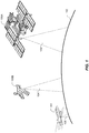
- FIG. 1 example embodiments of various spacecraft 100A, 100B and an aircraft 101 are shown orbiting or flying over the Earth 102.
- the International Space Station 100A is an example of a spacecraft and it is able to use an imaging system to capture a field of view 103 of the Earth 102.
- Another spacecraft is a satellite 100B which can use an imaging system to capture a field of view 104 of the Earth 102.
- other types of spacecraft including rockets, shuttles, satellites, microsatellites, nanosatellites, cubesats, and capsules, and generally spacecraft are herein generally referenced by the numeral 100.
- Aircraft 101 including airplanes, unmanned aerial vehicles (UAVs), helicopters, gliders, balloons, blimps, etc., can also be equipped with an imaging system to capture a field of view 105 of the Earth 102.
- marine vehicles e.g. boats, underwater vehicles, manned vehicles, unmanned vehicles, underwater or above-water drones, etc.
- sensing technology can be obtained, managed and processed using the principles described herein.
- Earth is used as an example in this document, the principles described herein also apply to remote sensing operations for other planetary objects.
- Non-limiting examples include asteroids, meteors, Mars, the Moon, the Sun, etc.
- spacecraft 100 and aircraft 101 orbit or fly at a distance above the Earth's surface to capture larger area of the Earth's surface. It can also be appreciated that the principles described herein are described with respect to spacecraft, but the principles also apply to aircraft.
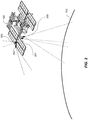
- FIG. 2 an example embodiment of spacecraft 100 (e.g. the International Space Station, is equipped with several cameras. Cameras 200 and 201 are pointed towards the Earth's surface to capture images of the Earth's surface.
- camera 200 is a Medium Resolution Camera (MRC) that has a larger field of view and camera 201 is a High Resolution Camera (HRC) that has a smaller field of view relative to the MRC.
- the spacecraft is also equipped with a camera 202 that points towards the horizon of the Earth.
- Another camera 203 is mounted on the spacecraft to point towards space, away from the Earth. The camera 203 can capture images in the general opposite direction of cameras 200 and 201. For example, camera 203 can capture images of the stars in space.
- a spacecraft 100 is able to orbit the Earth.
- a spacecraft is able to cover vast distances of the Earth very quickly, compared to an aircraft, and the spacecraft is able to stay positioned above the Earth for extended periods of time, compared to the aircraft.
- Non-limiting examples of other types of sensors that can be used to observe the Earth include LiDAR, RADAR, infrared sensors, and Synthetic Aperture RADAR (SAR). Other types of remote sensing technology also applies.
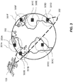
- the spacecraft 100 is shown orbiting the Earth 102 along an example orbit path 302.
- the spacecraft 100 captures and stores data, such as image data, and wirelessly transmits the data to ground stations on the Earth.
- a ground station generally referenced by the numeral 300, typically has to be within a certain position relative to the spacecraft 100 for data to be transmitted between the ground station and the spacecraft.
- the transmission regions of each of the ground stations is illustrated, for example, using the dotted circles 301A, 301B, 301C, 301D, 301E, 301F.
- the spacecraft and the given ground station are able to exchange data.
- the spacecraft 100 is within range of the transmission region 301 B of the ground station 300B located in North America
- the spacecraft and the ground station 300B can exchange data.
- the spacecraft can send or receive data from the ground station 300D.
- the spacecraft may be out of range of the ground station 300B located in North America.
- the ground stations are in communication with each other.
- FIG. 4 an example embodiment of a network system is shown.
- the spacecraft 100 may communicate to one or more of the ground stations 300A, 300B, 300C, ... ,300n at the same time or at different times.
- the ground stations are in communication with each other over a network 400.
- the ground stations include communication hardware (e.g. antennas, satellite receivers, etc.) to communicate with the spacecraft 100, computing devices (e.g. server systems) to store and process data, and communication hardware to communicate with the network 400.
- One of the ground stations 300A is a central ground station server which obtains the data from all the other ground stations.
- the central ground station stores and compiles all the data from the other ground stations together, and conducts the computing processes related to the data and any other data from external sources.
- another server 402 stores, compiles and processes the data from all the ground stations, including data from external sources.
- the other server 402 is not considered a ground station, but another server system.
- the network 400 may be wired network, a wireless network, or a combination of various currently known and future known network technologies.
- the network 400 may also be connected to the Internet or part of the Internet.
- User computing devices 401a, ..., 401n are in communication with the network 400.
- Non-limiting examples of user computing devices include personal computers, laptops, mobile devices, smart phones, wearable computing devices, and tablets. Users can use these computing devices to upload data (e.g. request for data, additional imagery, etc.) via the network, and download data (e.g. raw imagery or processed imagery) via the network.
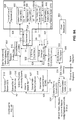
- FIG. 5 shows a decomposition of example components and modules of the Earth Observation System 500.
- the system 500 includes the following major components: the space segment 501, the ground segment 513 and the operation segment 528.
- the space segment 501 includes a Medium Resolution Camera (MRC) 502.
- the MRC includes a Medium Resolution Telescope (MRT) 503, a data compression unit (M-DCU) 504, and structure and thermal components 505.
- the space segment also includes a High Resolution Camera (HRC) 506, which includes a High Resolution Telescope (HRT), a data compression unit (H-DCU) 508, gyroscopes (GYU) 509, and structure and thermal components 510.
- the space segment also includes a star tracker unit assembly (STUA) 511 and a Data Handling Unit (DHU) 512.
- STUA star tracker unit assembly
- DHU Data Handling Unit
- the ground segment 513 includes the following systems, components and modules: an order management system (OMS) 514, a processing system 515, an archiving system 516, a calibration system 517, a control and planning system (CPS) 518, a ground station network 519 (which comprises the ground stations 300 and the network 400), an orbit and attitude system (OAS) 520, a health monitoring system (HMS) 521, a data hub 522, network and communications 523, a Web platform 524, a Web data storage system and content delivery network (CDN) 525, a product delivery system (PDS) 526, and a financial and account system 527.
- OMS order management system
- processing system 515 e.g., a processing system
- CPS control and planning system
- HMS health monitoring system
- CDN Web data storage system and content delivery network
- PDS product delivery system
- financial and account system 527 e.g., financial and account system 527.
- the systems, components and modules described in the ground segment are
- the operation segment 528 includes operation facilities 529, which are located at different locations and at the ground stations 300, and an operations team 530.
- the observation system 500 may also include or interact with external systems 540, such as public users 541, third party applications 542, customers and distributors 543, external data providers 544, community-sourced data providers 545, and auxiliary data providers 546.
- external systems 540 such as public users 541, third party applications 542, customers and distributors 543, external data providers 544, community-sourced data providers 545, and auxiliary data providers 546.
- the space segment 500 includes camera systems installed on the International Space Station (ISS), or some other spacecraft.
- the MRC 502 provides a medium resolution swath image of the Earth that is approximately 50 km across.
- the HRC 506 captures true video data, for example at approximately 3 frames/sec, having an area of approximately 5 km by 3.5 km for each image.
- Other cameras are mounted inside or outside the ISS looking out the windows.
- the system acquires image and video data and makes it available on the Web Platform 524 (e.g. a Website or application accessed using the Internet).
- the Web Platform 524 e.g. a Website or application accessed using the Internet.
- the benefits to users include constantly updating imagery.
- Image data is acquired to cover the accessible part of the Earth, with higher priority and quality given to areas of greater user interest.
- Image data such as video data and high resolution imagery from the HRC, is acquired for specific areas of interest based on predictions from the system 500 and from input from users.
- the Web Platform 524 provides a user experience that incorporates continually refreshed and updated data.
- the system is able to publish the remote sensing data (e.g. imagery) to users in near real time. Users (e.g. public user 524) will be able to interact with the platform and schedule outdoor events around the time when they'll be viewable from our cameras.
- the Web Platform will also integrate currently known and future known social media platforms (e.g. Twitter, Facebook, Pinterest, etc.) allowing for a fully geo-located environment with Earth video content.
- the API will be open source, allowing developers to create their own educational, environmental, and commercially focused applications.
- Requests include Earth observation data (e.g. both existing and not-yet acquired data) and value added information services.
- an online platform is provided that incorporates components of various currently known and future known online stores (e.g. Amazon.com, the Apple AppStore, Facebook, etc.).
- the online platform or online store allows consumers to search and purchase software applications developed and uploaded by third party developers.
- the applications have access to the images obtained by the Earth observation system 500, including images obtained by external systems 540.
- FIG. 6 a system diagram shows example components of the space segment 501.
- the space segment includes imaging and computing equipment that is mounted to or part of a spacecraft 100, such as the ISS.
- the spacecraft provides the utilities of electrical power, downlink communications of data, pulse-per-second (PPS) signal and time messages for absolute time stamping, uplink of command files and software or configuration table uploads, 2-axis pointing of the HRC 506, and accommodations of equipment and cosmonaut installation of the equipment.
- PPS pulse-per-second
- the space segment 501 includes the Biaxial Pointing Platform (BPP) 605, the On-board Memory Unit (OMU) 610, the TC1-S computer 611, the time synchronization signal generation 609, Internal Camera Equipment (ICE) 608, the Data Transmission Radio Engineering System (DTRES) 607 which is the X-band downlink transmitter, and the on-board S-band telemetry System 606 that is used to receive the command files and transmit real-time telemetry to the Mission Control Centre.
- BPP Biaxial Pointing Platform
- OMU On-board Memory Unit
- TC1-S computer 611 the time synchronization signal generation 609
- Internal Camera Equipment (ICE) 608 the Data Transmission Radio Engineering System (DTRES) 607 which is the X-band downlink transmitter
- DTRES Data Transmission Radio Engineering System
- the TC1-S 611 is configured to receive a set of commands used for imaging and downlinking in an Operational Command File (OCF). OCFs are configured to be uplinked through the s-band telemetry system to the TC1-S 611. The TC1-S 611 checks the OCF and then sends the OCF to the DHU 512 which controls the cameras.
- OCF Operational Command File
- Image data, video data, ancillary data, telemetry data, and log data is collected by the Data Handling Unit 512 and then transferred to the OMU 610. This data is then transferred from the OMU 610 to the DTRES 607. The DTRES 607 downlinks this data to ground stations 300 around the Earth.
- the Internal Camera Equipment (ICE) 608 would be used to provide imagery that is in addition to the MRC and HRC.
- the ICE includes, for example, a video camera pointed out of a viewing port to observe the earth's limb (e.g. camera 202), and a still-image camera would be pointed out a of different viewing port along nadir or as near to nadir as is possible.
- the cameras have a USB interface that can be used to get the data from the cameras into the DHU 512 to be subsequently downlinked. It will be appreciated that certain components (e.g. 512, 608, 609, 610, 611) are located inside the spacecraft 100 and other components are located outside the spacecraft.
- the main elements of the MRC 502 are the Medium Resolution Telescope (MRT) 503, which includes the focal plane and associated electronics, the Data Compression Unit (M-DCU) 504, the structure and thermal enclosure 505, and the corresponding cable harnesses and a connector box.
- MRT Medium Resolution Telescope
- M-DCU Data Compression Unit
- the MRT 503 is a fixed pointing 'push broom' imaging system with four linear CCD arrays providing images in four separate spectral bands.
- the images will have a Ground Sampling Distance (GSD) of approximately 5.4 m x 6.2 m and will cover a swath of 47.4km (at 350 km altitude).
- GSD Ground Sampling Distance
- the data from the MRT 503 is fed into the M-DCU 504 which uses a compression process (e.g. JPEG2000 or JPEG2K) to compress the data stream in real-time and then transmit the compressed image data to the DHU.
- a compression process e.g. JPEG2000 or JPEG2K
- the M-DCU 504 is also the main interface to the DHU 512 for controlling the camera. It gathers camera telemetry to be put into log files that are downlinked with the imagery, sets up the MRT 503 for each imaging session (e.g. sets the integration time), and performs the operational thermal control.
- the MRC 502 is able to take continuous, or near continuous, images of the Earth, producing long image strips.
- the image strips will be segmented so that each segment has a given set of parameters (i.e., compression ratio and integration time).
- Each image strip segment, made up of all 4 spectral bands, is referred to as an "Image Take" (IT).
- IT Image Take
- the imagery is divided into "frames", each of which are JPEG2000 compressed and downlinked as a stream of J2K files.
- Other compression protocols and data formats may be used.
- the integration time is varied in a series of steps over the course of the orbit, adjusting for the solar illumination level, including night imaging.
- the compression ratio may also be varied over the course of the orbit, according to the scene content. Images of the land with reasonable solar illumination levels may be acquired with relatively low compression ratios, yielding high quality products. Images of the ocean and land with low solar illumination levels, and all images at night may be acquired with higher compression ratios with little perceptible losses since they have much lower spatially varying content.
- An along-track separation of the bands can occur because the linear CCD arrays are mounted on a common focal plane, but spatially offset with respect to the camera bore sight.
- the image take data collected by the individual spectral bands of the MRC are acquired at the same time, but are not geo-spatially aligned.
- the NIR-band (leading band) will record a scene 6 to 7 seconds before the red-band (trailing band). This temporal separation will also cause a cross-track band-to-band separation due to the fact that the Earth has rotated during this period.
- the along-track and cross-track band-to-band spatial and temporal separations in the image take data sets are typical of push broom image data collection, and will be compensated for by the image processing performed on the ground by the processing system 515 when making the multi-band image products.
- elements of the HRC 506 are the High Resolution Telescope (HRT) 507, which includes the focal plane and associated electronics, the Data Compression Unit (H-DCU) 508, a 3-axis rate gyro system 509, the structure and thermal enclosure 510, and the corresponding cable harnesses and a connector box.
- HRT High Resolution Telescope
- H-DCU Data Compression Unit
- the HRT 507 is configured to produce full frame RGB video at a rate of 3 frames per second.
- the HRT video data is largely treated as a time series of independent images, both by the HRC 506 and the processing system 515.
- the HRT 507 is a large aperture reflective (i.e. uses mirrors) telescope which also includes a refractive element.
- the HRT also includes a Bayer filter and a two-dimensional, 14 Megapixel CMOS RGB imaging sensor on the focal plane.
- the image area on the ground is 5 km x 3.3 km with a GSD of 1.1 m when the space craft is at an altitude of 350 km.
- the data from the HRT 507 is fed into the HR-DCU 508 which compresses the data stream in real-time and then transmit the compressed image data to the DHU 512.
- the DCU 508 is also the main interface to the DHU for controlling the camera.
- the DCU 508 gathers camera telemetry to be put into log files that are downlinked with the imagery, sets-up the HRT for each imaging session (e.g., sets the integration time), and performs the operational thermal control.
- the imagery is divided into "frames", each of which are JPEG2000 compressed and downlinked as a stream of J2K files.
- the integration time for the HRC will be appropriately selected for the solar illumination level, including night imaging.
- the compression ratio will also be selected, according to the scene content. Videos of the land with reasonable solar illumination levels will be acquired with relatively low compression ratios, yielding high quality products. Videos of the ocean and land with low solar illumination levels, and all videos at night will be acquired with higher compression ratios with little perceptible losses since they have much lower spatially varying content.
- the HRC 506 is mounted to a two-axis steerable platform (e.g. the Biaxial Pointing Platform - BPP).
- the BPP 605 is capable of pointing the camera's bore sight at a fixed point on the ground and maintaining tracking of the ground target. For example, the BPP will rotate the camera to continuously point at the same target while the spacecraft is moving for approximately a few minutes.
- a 3-axis gyro system 509 is also included in the HRC 506 that measures the angular rates at high frequency. The system 509 sends this angular data to the DHU 512 to be downlinked as ancillary data. This angular data is used in the image processing on the ground to improve the image quality.
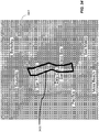
- a ground target may be a single point where all frames are centered on this one point, a 2D grid of points where a fixed number (e.g. 1-5) of frames is centered on each of the points in a serpentine sequence (resulting in a quilt-like pattern that covers a larger area), or a slowly varying series of points forming a ground track (following along a river, for example).
- the DHU 512 is configured to control the MRC 502 and HRC 506 via their associated DCUs 504, 508.
- the DHU 512 configures and controls the cameras, and receives and stores the image data from the MRC and HRC before transmitting the image data to ground stations 300.
- the DHU also receives and stores the gyro data from the HRC.
- the DHU 512 interfaces to a terminal computer 611.
- the terminal computer 611 receives the OCFs uplinked from mission control and transfers these files to the DHU 512 as well as inputs to ancillary data files and log files.
- the DHU 512 and the terminal computer 611 execute the time tagged commands listed in the OCF using their own internal clocks.
- the clocks are synchronized by use of a GPS-derived time synchronization signal (Pulse Per Second - PPS) to ensure that commands executed by both the DHU and the terminal computer are coordinated.
- PPS GPS-derived time synchronization signal
- the DHU also sends this same PPS signal to the Gyro Unit 509 in the HRC and to the Star Tracker Assembly Unit 511 so that the angular rate data and attitude data are also time synchronized to the commanding of the system.
- the DHU 512 Prior to each downlink, the DHU 512 sends the image and video data files to be downlinked, as well as the associated ancillary data and log files to the OMU 610 which then sends the data to the DTRES 607 for downlinking to a ground station 300.
- the space segment also includes a Star Tracker 511 to provide increased accuracy attitude knowledge of the camera mounting location and is therefore mounted in the vicinity of the two cameras 502, 506.
- the data from the Star Tracker 511 may be used by the terminal computer 611 in real-time to control the pointing angles of the BPP 605 so that a given target on the ground is tracked with improved accuracy.
- the star tracker data is also be sent to the DHU 512 from the terminal computer 611 as ancillary data to be used for the ground processing.
- Elements of the Star Tracker Unit Assembly (STUA) 511 include the Power and Interface Control Unit (PICU) 601, and two Star Tracker Heads 602, 603 (e.g. each pointed in a different direction).
- the STUA 511 also includes structural and thermal elements 604, such as a baseplate, secondary structural items (e.g., brackets), a thermal system (e.g. heaters, multi-layer insulation), and the associated cabling.
- the PICU 601 interfaces directly to the terminal computer 611 to provide the terminal computer 611 the real-time localized spacecraft attitude data that may be used to control the BPP 605.
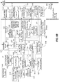
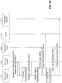
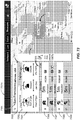
- FIG. 7 and FIG. 8 example components of the ground segment 513 are shown in relation to each other.
- the solid connection lines show the flow of imagery and video data
- the dotted lines show the flow of other data (e.g. orders, requests, and control data). It can be appreciated these data flows are only examples, and that the direction and type of data flowing between the different components can be different from what is illustrated in FIG. 7 .
- ground station networks 519 which include ground stations 300.
- FIG. 7 and FIG. 8 there are a number of external entities that can interact with the earth observation system.
- Public Users (541): General public users can use the Web, internet, and mobile interfaces to look at imagery, video, and other information and to also contribute their own inputs.
- Third Party Applications Applications developed by third parties are configured to interact with the earth observation system's Internet services and resources via an application programming interface (API). The applications are expected to support mobile devices.
- API application programming interface
- Customers are those customers that place orders for new collections or specifically generated image and data products.
- External Data Providers In addition to the data acquired from the spacecraft 100, the ground segment of the earth observation system is configured to acquire imagery, video, and other data from External Data Providers such as other satellite data suppliers.
- Data including image and video, may also be obtained from the general public.
- Auxiliary Data Providers provide supporting data such as Digital Elevation Models (DEMs), Ground Control Points (GCPs), Maps, and ground truth data, to the Earth observation system, such as the calibration system 517.
- DEMs Digital Elevation Models
- GCPs Ground Control Points
- Maps Maps
- ground truth data ground truth data
- the Earth observation system includes a number of components, such as the Web platform 524.
- the Web platform 524 provides a Web interface to the general public. It includes capabilities to: browse and view imagery, videos and other geographic data; contribute additional information and social inputs; and accept requests for future data collection activities.
- the Web Data Storage & Content Delivery Network (Web DS & CDN) 525 includes cloud infrastructure that is used to store the Web image data, video data, and community-sourced data, and distribute the data around the world using a Content Delivery Network (CDN) service.
- CDN Content Delivery Network
- the earth observation system also includes a Product Delivery System (PDS) 526.
- PDS Product Delivery System
- the PDS includes online storage that is used to serve up Products for retrieval by Customers/Distributors.
- the Order Management System (OMS) 514 accepts orders for products and services and manages the fulfillment of those orders.
- the OMS is configured to task the CPS 518 for new acquisitions and the Processing System 515 for processing. Orders are tracked and feedback is provided to users.
- the Control and Planning System (CPS) 518 is configured to provide the following functionality: assess the feasibility of future acquisitions; re-plan future acquisitions and downlinks to assess and adjust the feasibility of the overall collection plan for an upcoming time period; and, based on a resource model and updated resource status received from the mission control center (MCC) 530 and the ground station network (GSN) 519, create plans and command files for onboard activities including imaging and downlinks, and tasks for the GSN 519.
- MCC mission control center
- GSN ground station network
- the Accounting & Financial, Billing and Customer Management Systems 527 are the general systems that are used to manage the sales and monetary funds of the image data and imaging services.
- the Archiving System 516 archives the raw MRC & HRC image and video take data and associated ancillary data.
- the Processing System 515 performs several functions.
- the processing system 515 processes the raw camera data to create image tiles (i.e. map tiles), near real-time live feed tiles, and video files for the Web platform 524. This includes, for example, additional compression and other degradation (e.g. adding watermarks) to differentiate this data from the data that is sold to Customers/Distributors 543.
- the processing system 515 also processes the data received from External Data Providers 544 and community-sourced data providers 545 to create image tiles and video files for the Web platform 524.
- the processing system 515 also processes the raw MRC and HRC data to generate the image products and video products for the Customers/Distributors 543.
- the data for the customers/distributors 543 is of higher quality compared to the data provided on the Web platform 524. In this way, data presented on the Web platform 524 can be more easily displayed and consumed by lower power user devices, like tablets, mobile devices and laptops.
- the Calibration system 517 monitors the image quality performance of the system and generates updated parameters for use in the rest of the system. This includes creating HRC and MRC radiometric and geometric correction tables that will be provided to the Processing system 515.
- the correction tables may include gains and offsets for the radiometric correction, misalignment angles, and optical distortion coefficients for the geometric correction.
- the Calibration system 517 also includes automated functions to monitor the characteristics of the HRC and MRC and, when necessary, perform updates to the radiometric and geometric correction tables.
- the Calibration system 517 may also include tools to allow the operators to monitor the characteristics of the HRC and the MRC, and the tools may also allow operators to perform updated to the correction tables.
- the Ground Station Network (GSN) 519 is the collection of X-Band Ground Stations that are used for the X-Band downlink of image, video, ancillary, and log data.
- the GSN is a distributed network of ground stations (e.g. ten ground stations) providing for frequent downlink opportunities.
- the Data Hub 522 is responsible for collecting, preprocessing and routing of downlink data.
- the Health Monitoring System (HMS) 521 is configured to perform a number of functions.
- the HMS monitors the health status of the space segment 501, and generates of health status reports.
- the HMS organizes and stores engineering telemetry and diagnostic logs, which can be transmitted to an operator for viewing.
- the HMS also logs behavior and performance, such as by computing long-term trends and statistical analysis.
- the HMS is also configured to receive and store engineering inputs for the generation of maintenance, configuration and diagnostic activities of the space segment 501.
- the HMS is also configured to monitor general performance of the Ground Station Network (GSN). For example, the HMS monitors signal levels and lock synchronization, and may monitor other characteristics.
- GSN Ground Station Network
- the Orbit & Attitude System (OAS) 520 publishes definitive and predicted orbit data, definitive and predicted attitude data of the ISS.
- the OAS also provides some related orbit and attitude related services to the rest of the system.
- the Mission Control Center (MCC) 530 is used to manage communications between the spacecraft 100 and the ground.
- the MCC station is used for uplinking the command files (e.g. OCFs) and receiving real-time heath and status telemetry.
- the MCC 530 is also configured to transmit resource availability about the spacecraft and the space segment 501 to the CPS 518. This resource availability data may include data regarding power resources, planned orbit adjustment maneuvers, and any scheduled outages or other availability issues.
- the MCC 530 receive OCFs from the CPS 518.
- the MCC 530 then confirms that it meets all resource constraints and availability constraints. If there is a conflict where any resources are not available to optical telescope system, it will either request a new plan from the CPS 518 or could cancel some imaging sessions to satisfy the constraint.
- FIG. 7 and FIG. 8 also show secondary systems or external systems 701 that may be used in conjunction with the systems described above.
- These secondary or external systems include a data hub 522', a processing and archiving system 515', 516', a health monitoring system 521', an orbit and attitude system 520', an order and management system 514', a network hub 523', and a ground station network 519'.
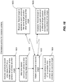
- FIG. 8 maps the letters used to identify types of data flowing between the different systems.
- FIG. 8 shows the letter 'A' located on the data link between the processing system 515 and the external data providers 544.
- the letter 'A' means that other raw imagery and ancillary data, as well as other product imagery and metadata are exchanged between the processing system 515 and the external data providers 544.
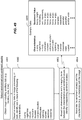
- Other letters used in FIG. 8 are detailed in the table below. TABLE 2: Data Flow Mapping for FIG.
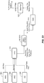
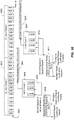
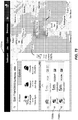
- FIG. 9A and FIG. 9B show different parts of the same system diagram, which includes the components of the ground segment and the components of the space segment. The components or systems are the same as those described above.
- FIG. 9A further includes a power distribution unit 901 that is in communication with the terminal computer 611 on the space segment.
- FIG. 9A and 9B the links between the components or systems further show reference IDs (e.g. E8, E23, 111, 123, etc.). These reference IDs are used to explain the interfaces between two components and are further described using Table 3A and Table 3B below.
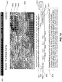
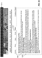
- TABLE 3A Reference IDs Used for Interfaces in FIG. 9A ad FIG. 9B ID Name Description Space Segment Interfaces E8 DHU to TC1-S • OCFs • Direct Commands • ISS Ancillary Messages • Time Messages • TC1-S Telemetry • DHU Telemetry E8 DHU to OMU • Downlink Transfer Files (DTF) E9 HRC to ISS-RS • External interfaces between HRC and equipment on the ISS RS.
- DTF Downlink Transfer Files
- FIG. 9A ID Name Description Space Segment Interfaces I1 HRT to HR-DCU • Electrical interface between the High Resolution Telescope (HRT) and the High Resolution Data Compression Unit (HR-DCU). • HRT command and control • HRT power from HR-DCU • HRT programming and configuring • HRT data definition I2 MRT to MR-DCU • Electrical interface between the Medium Resolution Telescope (MRT) and the Medium Resolution Data Compression Unit (MR-DCU). • MRT command and control • MRT power from MR-DCU • MRT programming and configuring • MRT data definition I3 DHU to HR-DCU and MR-DCU • Data and electrical signal interface between the DHU and High Resolution Data Compression Unit (HR-DCU).
- HR-DCU High Resolution Telescope
- HR-DCU High Resolution Data Compression Unit
- I6 Web Platform to OMS Web platform provides filtered lists of requests for the HRC video and MRC image targets.
- Request and Status TBD
- Web User Collection Plan TPD
- OMS provides Reports that contain upcoming planned Acquisitions that can be displayed by the Web Platform I7 Web Platform to Archiving System • Catalogue query I8 Processing System to Web Platform • Community-sourced data arrival notification I9 GSN to Data Hub • Raw Product I10 Data Hub to Processing System • HRC/MRC/ICE Image/Video Data (Level-0) • Ancillary Data Level 0 I11 Processing to Web Storage & CDN • Processed MRC simulated videos, HRC videos, MR images and HR images for cloud data storage (online) • Processed image data also from external data suppliers also added to the cloud data storage • Community sourced image data sent to processing and the processed data then added to the cloud data storage I12 Data Hub to OMS Data Hub Logs • Workflow Control Files ID Name Description I13 Processing System to PDS • Products I14 OMS to Processing System • Product Generation Request & Status • Image/
- ancillary data for Level 0 products include orbit position, attitude and other data used for processing.
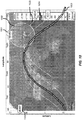
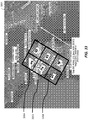
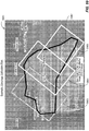
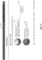
- FIG. 10 an illustration show an image of a spacecraft 1000 travelling at a certain latitude and longitude 1002, 1001, along an orbit path 1003.
- He segments in the orbit 1003 show the sections of video or image data acquired. For example, each section corresponds to an image take.
- Other orbit paths 1005 and 1004 can be used.
- any module, component, or system exemplified herein that executes instructions or operations may include or otherwise have access to computer readable media such as storage media, computer storage media, or data storage devices (removable and/or non-removable) such as, for example, magnetic disks, optical disks, or tape.
- Computer storage media may include volatile and non-volatile, removable and non-removable media implemented in any method or technology for storage of information, such as computer readable instructions, data structures, program modules, or other data, except transitory propagating signals per se.
- Examples of computer storage media include RAM, ROM, EEPROM, flash memory or other memory technology, CD-ROM, digital versatile disks (DVD) or other optical storage, magnetic cassettes, magnetic tape, magnetic disk storage or other magnetic storage devices, or any other medium which can be used to store the desired information and which can be accessed by an application, module, or both. Any such computer storage media may be part of the systems, modules or components of the Earth observation system 500, or accessible or connectable thereto. Any application, system or module herein described may be implemented using computer readable/executable or instructions or operations that may be stored or otherwise held by such computer readable media.
- FIG. 11 a perspective view of the camera system is shown mounted on the spacecraft 100.
- the illustration shows the MRC 502, and the HRC 506 mounted to the BPP 605.
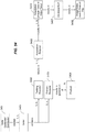
- FIG. 12 an example embodiment of a system diagram of the space segment is shown, including the camera system MRC 502 and HRC 506. It can be appreciated that other camera configurations, other than the configurations described herein, can be used with the principles described herein.
- the terminal computer 611 controls operations on the DHU 512.
- the terminal computer also controls the MRC and HRC units' power on/off transitions in accordance with the OCF content.
- the terminal computer 611 provides time updates, Operational Command Files (OCFs 1201), direct commands, spacecraft ancillary data (e.g. ephemeris and attitude data, BPP joint angles, STUA quaternions), and terminal computer telemetry data to the DHU 512.
- OCFs 1201 Operational Command Files 1201
- direct commands e.g. ephemeris and attitude data, BPP joint angles, STUA quaternions
- terminal computer telemetry data e.g. health status
- the Mission Control Center (MCC) 530 located on the Earth, performs checking on the OCFs. If no issues are found, MCC manages the uplink of the OCF to the spacecraft. If any issues are found, the OCF is rejected and is not sent to the spacecraft.
- the MCC manages the uplink of the OCFs via ground stations.
- the size of the command data that can be uplinked in one pass is limited. For example, the command data in an OCF is less than 8800 bytes. However, the limit varies from pass to pass (e.g. when the spacecraft passes over a region of a ground station). The MCC will enforce this restriction and will only uplink OCFs that fit within the restriction.
- the CPS 518 sends OCFs to the MCC 530 and the MCC manages the communications with the spacecraft via the terminal computer 611.
- the MCC also received telemetry from the terminal computer 611, including health and safety data.
- the health and safety data is sent from the spacecraft to a ground station 300 via the spacecraft's DTRES.
- space packets of data are generated by the terminal computer 611, and stored on the OMU 610 of the spacecraft.
- the space packets include image data (e.g. image take files 1206 and video take files 1207), ancillary data files 1204 and health monitoring data (e.g. log files 1205).
- image data e.g. image take files 1206 and video take files 1207
- ancillary data files 1204 e.g. log files 1205
- health monitoring data e.g. log files 1205
- the space packets are sent from the OMU to the ground station 300, via the DTRES 607.
- the ground station sends the data to a data hub 522.
- the space packets, including the log files are sent to the HMS 521.
- the space packets including the ancillary files 1204, the image take files 1206, and the video take files 1207 are sent to the processing system 5
- the terminal computer 611 is configured to, for each Session in the OCF, execute the necessary steps to power on/off the DHU 512, STUA 511, MRC 502 and HRC 506. In some cases, the terminal computer 611 powers on/off the OMU 610 and DTRES (e.g. X-band transmitter) 607 to support the downlinks. For each STUA Session in the OCF, the terminal computers 611 execute the STUA commands. For each HRC Session in the OCF, the terminal computer executes the BPP control.
- OMU 610 and DTRES e.g. X-band transmitter
- the terminal computer 611 When the terminal computer 611 receives a new OCF, the terminal computer performs a check on the OCF. If any errors are found the OCF is discarded and is not passed onto the DHU 512. This occurrence would be reported to the DHU via an execution message and passed to the ground in a Space Segment Log (e.g. log file 1205).
- a Space Segment Log e.g. log file 1205.
- the terminal computer 611 is configured to modify an OCF by deleting, inserting, or modifying commands.
- the terminal computer introduces unplanned instructions (e.g. instructions not contained in the originally received OCF) to activate power off cycles to support off-nominal operations aboard the spacecraft.
- the DHU 512 After receiving a new OCF from the terminal computer 611, the DHU 512 computes a basic check on the OCF format and, if there is a discrepancy, the DHU 512 rejects the OCF. This discrepancy and rejections would also be noted in the Space Segment Log.
- the DHU 512 generates internal command schedules based on the contents of the OCF. In addition to controlling its internal activities, the DHU 512 will control the MRC and HRC. This includes power on/off and any necessary warm-up / cool-down periods. In particular, the DHU sends MRC commands to the MRC 502, HRC commands to the HRC 506, gyro commands to the gyroscopic unit 509. The DHU also received image or video data from the cameras, telemetry data from the cameras, and telemetry data from the gyroscopic unit.
- the GPS 1202 on the spacecraft is used to obtain the time and PPS.
- the time is sent to the terminal computer and the DHU.
- the PPS is sent to the DHU, and the DHU transmits the PPS to other components (e.g. 509, 511).
- the internal camera equipment, or other camera equipment can be controlled using OCFs and the DHU in the same way the HRC and MRC are controlled.
- the data from these other cameras can be downlinked and processed in the same or similar way data from the HRC and MRC are handled.
- the DHU and the terminal computer are configured to process each OCF to create the internal commanding schedules without affecting the current schedule being executed.
- the DHU and the terminal computer are configured to stop all activities associated with the previous OCF at the start time of the new OCF and generate their new internal schedule based on this new OCF from that start time.
- Configuration parameters includes software patches, calibration and configuration settings.
- the specific configuration instructions that may be commanded include the update and dump of MRC and HRC configuration factors, uploading of any of the telescope configuration tables, update of compression selection tables, DHU configuration, software updates.
- Software updates may be in the form of OCFs and the transport mechanism could be via the normal command uplink to the terminal computer 611. However the updates could also be, via memory stick, sent up on a flight to the spacecraft, where an astronaut or cosmonaut (or the like) inserts the memory stick into the terminal computer.
- the MRC is a fixed pointing camera that takes image strips.
- the configurable camera settings include ADC gain, integration time and compression ratio. The following are some overall considerations related to compression ratio, integration time. Examples of compression ratios for the MRC are provided below in Table 4. Table 4: Compression Ratios for MRC Example Compression Ratio Example intended application for Imagery 4:1 Highest quality 8:1 Lowest acceptable level of quality for land imagery (including for Web use) Greater than 8:1 Ocean or night
- An Image Take is a contiguous strip of four-band MRC data collected with the same camera and configuration settings.
- Four-band data refers Red, Green, Blue and Near Infrared (RBGN) data.
- RBGN Near Infrared
- all image takes will have a unique Image Take ID.
- the MRC camera is primarily operated in a systematic image collection mode.
- the MRC camera collects imagery all the time, subject to resource constraints. Based on this mode of operation, most of the MR imagery will be part of a systematic background acquisition plan. Most of the imagery will be acquired as long strips.
- the length of individual strips (Image Takes) is limited in practice by the need to change the ADC gain, integration time and compression ratio as the sun illumination changes along the orbital ground track. This limit may be reached sooner than other limits, such as limits in the size of data that can be downlinked and handled in the rest of the system.
- a request for imaging using the MRC can originate from a customer or external user are managed by OMS and allow a user to: request that imagery of a certain area is covered; request certain compression level (e.g. higher quality than the default setting); and request delivery to the customer.
- the request may also include details that exclude or delay the imagery from being placed in the public archive.
- the default imaging routine of the MRC is systematic and includes capturing long images of strips of the Earth. The image strips are broken or separated into manageable lengths during planning. The systematic imaging is not done in response to any specific user requests.
- the imaging concept for the MRC is for continuous global coverage. However the specific Acquisitions may be influenced by: light conditions; land or ocean area; and data volume limitations on board or downlink capacity
- the operational Image Take executable instructions may be performed according to the following order: MRC On command; MRC Warmup delay; one or more Image Takes; MRC Power-off clean-up delay; and MRC off command.
- the HRC is an agile high-resolution video camera. For example, it has capture images at 3 frames per second, optionally decimated by integral factors.
- the HRC is capable of collecting video/imagery in several ways.
- the HRC is configured to capture video centered on a single target on the ground.
- the camera remains pointed at the target as the spacecraft moves along its orbit.
- a video with one frame is equivalent to acquiring a single image.
- Sets of such videos or images can be used for specific purposes such as stereo pairs. If the images are not frames of a continuous video, then such scenarios are composed of multiple Image Takes.
- the HRC is also configured to capture a one-dimensional or a two-dimensional grid of adjacent single frame takes where a fixed number (e.g. 1-5) of frames are acquired in a line or serpentine pointing sequence, resulting in a quilt-like pattern that covers an area longer and/or wider than a single swath.
- a fixed number e.g. 1-5
- Such an imaging scenario can be commanded such that it is stored as a single Video Take.
- the HRC is further configured to capture a video of a path on the ground (a video that slides along a path on the ground).
- a video that slides along a path on the ground Such an imaging scenario can be commanded such that it is stored as a single Video Take.
- the HRC is also configured to capture a video of a celestial target (e.g. the moon).
- the HRC's configurable camera settings include, for example, ADC gain, integration time and compression ratio. The following are some considerations related to compression ratio, integration time and ADC gain settings. Typical compression settings for the HRC are shown in Table 5 below. TABLE 5: Example Compression Ratios for HRC Example Compression Ratio Example intended application for Imagery 3.3:1 Highest Quality 4:1 Nominal Between 8:1 and 15:1 Minimum quality for Web
- a Video Take is defined as a set of HRC frames taken of a specific target. During this period, the BPP 605 will normally point the HRC boresight at the target and track this target during the VT. Each VT has constant camera and compression configuration settings.
- the HRC may be operated in an order driven mode. These orders could originate from various sources, including Customers/Distributors, planners, and inputs from Public Users. The orders will specify targets, areas, or paths.
- the HRC operations include, for example, single target video, capturing a grid of images to cover an area, a video of a path, and celestial target video.
- commands from the ground segment give the space segment coordinates of points on the Earth at which to point the HRC.
- the computing terminal 611 is configured to calculate the BPP pointing angles and commands the BPP.
- the CPS 518 is responsible for determining the timing of the HRC imaging activities such that slew and settling time rules are followed.
- the Order specifies the target's latitude, longitude and altitude.
- the BPP slews from the previous location, settles, and then dwells on the target for the entire Video Take.
- the result of this type of imaging is a video (or image if the video has only one frame) centered over a target.
- the Order specifies an area polygon. At the time of order entry, limits are automatically placed on the size of the area, based on the maximum area that the camera can acquire in one pass.
- the CPS 518 takes the requested area and breaks it into a series of individual single target Video Takes that form a grid pattern to cover the area.
- the BPP 605 slews from the previous location, settles, and then dwells on the first target for the duration of a single frame.
- the BPP 605 then slews, settles, and dwells on the second target for another single frame. And so it continues through all the individual single target Video Takes.
- the Order specifies a path expressed as a sequence of video center coordinates.
- the CPS 518 creates a sequence of target center coordinates with appropriate spacing along the requested path.
- the BPP 605 slews from the previous location, settles, and then "sweeps" smoothly through each of the target center coordinates over the total Video Take duration.
- the required integration time (e.g. based on lighting level) determines the frame rate which determines the maximum path length. Based on typical values for integration time a swath of up to approximately 20 km could be swept. The result of this type of imaging is a single video that "sweeps" or “pans” over a path on the ground.
- the order contains a coordinate in RAAN, Declination format.
- the BPP slews from the previous location, settles, and then dwells on the target for the entire Video Take.
- the result of this type of imaging is a video (or image if the video has only one frame) centered on a target.
- the HRC operation executable instructions are executed according to the following timeline: HRC on command; gyro warm up delay; BPP on command; BPP align delay; HRC warm up delay; one or more Video Takes; BPP slews to position; acquisition begins and BPP tracks target position; at the end of the Video-take the BPP slews to its next position and wait to start the next video take; at the end of the last video take in the current HRC Session, the BPP performs a final slew manoeuvre to its stowed position, if so commanded; HRC Power Off Cleanup delay; HRC Off Command; and BPP Off Command.
- example computer executable instructions are provided for determining camera configuration parameters.
- the parameters may apply to the MRC 502 and the HRC 506.
- These executable instructions may be performed on the space segment or the ground segment, or portions may be performed on the space segment and portions may be performed on the ground segment.
- a computing device executes the instructions.
- the computing device may include many computing devices (e.g. a computing device located on the ground and a computing device located on the spacecraft).
- a computing device determines solar illumination level of the Earth, of which the camera will capture images and video.
- the solar illumination is be estimated based on location, date, and time of day at location, or can be obtained from measurements.
- the computing device determines integration time of the camera based on the solar illumination level (e.g. night time has a higher integration time).
- the computing device outputs the integration time for the camera.
- the computing device determines the ADC gain based on the solar illumination level (e.g. higher ADC gain for high solar illumination), as per block 1304.
- the output is the ADC gain 1305.
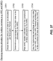
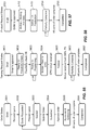
- the computing device determines if the time of day is "night" for the location viewed by the spacecraft (block 1306). If so, and it is night, the computing device outputs a "high" compression ratio (block 1307). This is because there is little data to be obtained from night images, and higher quality images are not required for the night images. If the time of day for the specific location is not night (e.g. is the "day time"), the computing device determine the scene content (e.g. estimate based on location viewed by spacecraft) (block 1308). If the scene content is the ocean or water, the computing device outputs a "high" compression ratio (block 1309).
- the scene content e.g. estimate based on location viewed by spacecraft
- the output is a "high" compression ratio (block 1310). If the scene content is land with sufficiently high solar illumination, then the output is a "low” compression ratio (block 1311). It can therefore be appreciated that, by automatically adjusting the camera settings based on these factors, the size of the data files are appropriately smaller for less important images and are appropriately larger for more important images. This saves resources related to data storage and transfer.
- FIG. 14 computer executable instructions are provided for camera operation and data acquisition.
- the instructions are performed by a computing device on the space segment.
- the computing device obtains camera setup parameters, such as per FIG. 13 .
- the computing device performs operational thermal control of the camera to maintain temperature stability.
- the computing device instructs the camera to capture image data (e.g. still images and/or video images).
- the computing device compresses the data stream in real-time according to compression ratio (i.e. a camera operation parameter).
- the computing device obtains ancillary data (e.g. location, telemetry, etc.) (block 1406).
- the computing device stores the compressed image data, along with associated telemetry, camera setup parameters, and other ancillary data, in the on-board memory unit (OMU) (block 1407).
- the computing device then sends the compressed image data, along with associated telemetry data, camera setup parameters, and other ancillary data, to one or more ground stations via downlink (block 1408).
- OMU on-board memory unit
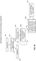
- example computer executable instructions are provided for determining when to automatically power on or power off a camera on the spacecraft.
- the instructions include obtaining the location of the spacecraft over the Earth and the time.
- the location and time may be current location and time, or may be a future location and future time (e.g. several minutes or several hours in the future).
- the instructions include obtaining visibility parameter(s) for the location and the time (e.g. darkness/light, cloudy/clear).
- a computing device can estimate darkness/light based on the time and date, and comparing the same with a database of sunrise and sunset times (block 1556).
- the computing device estimates cloudy/clear weather based on weather forecast and reports (block 1506).
- the instructions include determining an interest factor based on with location and visibility parameter (block 1503). For example, a default interest factor is used, and the default interest factor is associated with the determined location, time and visibility parameter. Alternatively, the interest factor is determined using a custom/override interest factor for certain conditions (e.g. based on customer orders or certain events). See block 1507.
- a default interest factor is used, and the default interest factor is associated with the determined location, time and visibility parameter.
- the interest factor is determined using a custom/override interest factor for certain conditions (e.g. based on customer orders or certain events). See block 1507.
- the computing device activates power or deactivates power for the camera based on the interest factor (block 1504). For example, if the interest factor is sufficiently high, activate power to the camera, or otherwise deactivate power to the camera (block 1508).
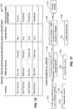
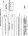
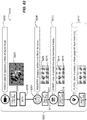
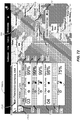
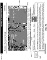
- FIG. 16 an example of a table 1601 is used to determine a default interest factor for block 1503.
- the table considers location and visibility factors to determine an interest factor and corresponding power activation command. For example, if the location is San Francisco, the time is during the day time, and there is a clear sky, then the interest factor is high. Thus, the camera is activated. However, for similar conditions, but where the location is a water body (e.g. the Pacific Ocean), the interest is low. As there is typically little interest of images of water, the camera is deactivated to save power.
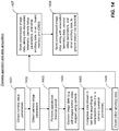
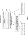
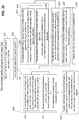
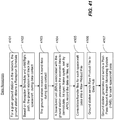
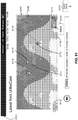
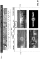
- FIG. 17 describes another set of computer executable instructions.
- a computing device determines the answers to the following conditions: is the spacecraft located over a location interest? (block 1701); is the time of day for the location interest during the daylight period? (block 1702); and is the atmospheric visibility sufficiently clear for the location of interest? (block 1703). When all of these conditions are met, the camera is activated (block 1707). Otherwise, the camera is deactivated (blocks 1702, 1704, 1706).
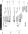
- example computer executable instructions are provided for controlling orientation of a rotatable camera, such as the HRC 506 mounted to the BPP 605.
- the instructions include activating a camera to record video takes (VT) for a certain time period, where the camera is oriented at a first angle (block 1801). After a time period has passed, the instructions include commanding the camera to stop recording, but still keeping the camera on or powered (block 1802).
- the computing device executes instructions to rotate the camera to a second angle (block 1803). For example, the second angle is selected to point the camera at the same target position when the camera was at oriented at the first angle (block 1805).
- the second angle is selected to point the camera at a different target position compared to when the camera was oriented at the first angle (block 1806).
- the instructions include activating the camera to record another VT for a certain time period, where camera is oriented at the second angle. It can be appreciated that, in this example embodiment, the camera does not record video when the camera is being reoriented between video takes.
- example computer executable instructions are provided for controlling the BPP 605.
- the instructions include: activating power for the camera (e.g. HRC) and for the gyros (block 1901); activating the BPP (block 1902); executing an alignment procedure for the BPP (block 1903); slewing the BPP to a starting position for a video take (VT) (block 1904); rotating the BPP to track a target location (e.g.
- target location can change over time) (block 1905); starting recording of the VT using the camera, while simultaneously rotating the BPP to track a target location (block 1906); ending the recording of the VT (block 1907); and slewing the BPP to a new starting position of a new VT, or back to a stowed position (block 1908).
- the process starts again from block 1904. Otherwise, if the BPP is moved to a stowed position, the computing device determines if more than a predetermined amount of time passed since last VT (block 1909). If so, the computing device executes a re-alignment procedure for the BPP (block 1910). This realignment is to take into account the vibrations that may have caused the camera to be misaligned while being in the stowed position. If the predetermined amount of time has not yet passed, no action is taken, and the computing device re-evaluates the condition posed in block 1909.
- a computing device on the spacecraft 100 determines if a connection (e.g. a line of sight) is available between spacecraft and a central ground station (GSN) or a secondary ground station (GSN). If there is no connection to any ground station, the computing device on the spacecraft waits and then repeats the search for connectivity (block 2002). If the spacecraft connects to the central ground station, the computing device on the spacecraft downlinks data to the central ground station (block 2004).
- the central ground station 300A receives the data from the spacecraft (block 2007), and may receive data from one or more secondary ground stations (block 2008). The central ground station then compiles the data and removes duplications of data (block 2009).
- the computing device on the spacecraft downlinks the data to the secondary ground station (block 2003).
- the secondary ground station receives the data from the space craft 2005 and sends the data to the central ground station 2006, for example, over the network 400.
- the data is received by the central ground station at block 2008.
- the spacecraft can communicate data to another ground station and the data will be compiled on Earth.
- example computer executable instructions are provided, which can be implemented by the DHU 512 to perform the downlinking of files.
- obtains the following information e.g. via OCF: downlink windows; and, for each image/video take, the permitted ground stations.
- OCF may designate which images, based on location or timing, or both, may be permitted to be sent to only certain ground stations.
- the DHU performs planning operations to determine which files are to be downlinked in each downlink window for a given ground station.
- the DHU has a set of logic rules that implement querying priority.
- the DHU populates a downlink list with an ordered list of files to be downlinked, as per the derived plan (block 2103).
- the DHU then downlinks the files according to the downlink list (block 2104).
- FIG. 22 an example embodiment of computer executable instructions are provided for downlinking data and data handling, involving elements from both the space segment and the ground segment.
- the spacecraft 100 downlinks the data to a ground station, which records the data and sends it on to the Data Hub 522.
- the Data Hub re-assembles the Image/Video Take files which may have been split across several passes and ground stations.
- the Data Hub 522 forwards them to the Processing System 515.
- the Processing System catalogues the new data, and then generates the systematic products which are sent to the Web DS & CDN 525.
- the CPS 518 sends a reception schedule 2202 to the ground station network 519 and sends the expected file list 2203 to the data hub. This occurs at the end of a planning session 2204.
- the spacecraft using components 606, 607, downlinks the image and video data via an X-band downlink 2205.
- a set of operation 2208 are performed for each downlink pass at each ground station.
- the ground station receiving the data sends a compiled data file 2206, like a Cortex Data File, to the data hub 522 and sends a post-pass report 2207 to the CPS 518.
- the data hub For each downlink pass received from a ground station, the data hub re-assembles the received files 2209. It is noted that Application Identifiers (APIDs) are embedded into the DATA ID and include SOF and EOF markers, which used to help reassemble the files. After assembling the files, the data hub sends Level 0 Files and a data quality report 2210 to the processing system 515. The assembled Cortex data file (2211) is also sent to the E-Data Hub 2201. The data hub also sends the data hub log to the CPS and the OMS (2212).
- APIs Application Identifiers
- the processing system then performs a cataloguing process (2214) and then sends Level 0 files and catalogue entries to the archiving system (2215).
- the processing system also performs additional processing 2216 to generate map tiles, live-feed tiles and pinpoint data, amongst other types of processed data.
- the processed data is sent to the Web DS & CDN (2217).
- the image video take notification is sent to the OMS, for example to alert the users that their data has been acquired and is ready for downloading.
- FIG. 23 the flow diagram shows the flow of image or video data from the space segment to the ground segment.
- the DHU 512 receives compressed blocks of imagery/video from the DCU in each camera 502, 506, 608.
- the DHU 512 assembles these blocks into Downlink Files composed of space packets.
- Each file stored on the DHU will have a unique DHU Data ID which serves as a handle for the particular type of file to be accessed.
- the DHU Data ID for Image/Video Take files contains the Image/Video Take ID that was specified in the OCF.
- the output from the DCUs in each camera to the DHU is a stream of image files.
- the DHU will manage the collection of these image files belonging to a single Image Take or Video Take as one file.
- the IT or VT will be uniquely identified by an ID included as part of the record command in the OCF. This same ID will be used to identify the file to the DHU when it is included in a downlink list, a delete list, or a do-not-delete list.
- API Application Identifier
- CCSDS Consultative Committee for Space Data Systems
- ancillary data and log information from both the camera systems and the spacecraft are used by the ground segment to monitor and control the collection of data, and also process the collected data. It may also be used by systems onboard to determine the status of other systems, for example for the DHU to monitor the status of the HRT and MRT.
- the DHU is configured to receive ancillary data from the following different sources: the terminal computer 611 (e.g. the spacecraft position, the spacecraft attitude, BPP pointing angles, etc.); the HRC - DCU 508 (e.g. temperatures, dark pixel data, etc.); the HRC - Rate Gyros 509 (e.g. configuration settings); the MRC - DCU 504 (e.g. temperatures, dark pixel data, etc.); and from the DHU itself (e.g. status information).
- the DHU collects this data and periodically saves the data to a file, such as an ancillary data file and a DHU data log. A new file is created each time the data is saved.
- the DHU collects log information from the same sources used to collect ancillary data.
- Log data is collected and written to files in the same manner as the Ancillary Data.
- the log data includes, for example, the execution result of each command in the OCF, and health/status telemetry.
- FIG. 24 a flow diagram shows the flow ancillary data and log data from the space segment to the ground segment.
- ancillary data is downlinked upon request from the ground, by time window. Data files that overlap the requested time window are downlinked. The DHU automatically deletes the oldest files to clean up memory space.
- the OCF contains downlink commands to indicate the times of downlink passes and to indicate the data to be downlinked in each pass.
- the DHU will create a list of files to be downlinked by taking the downlink list in the OCF, and the DHU will add other files based on predetermined and configurable rules.
- the DHU may arrange for the files for downlinking to be transferred to the OMU just before the downlink start time.
- the transfer between DHU and OMU may be done in partitions based on data size (e.g. 1 GB). This means that a single Image/Video Take may be split up across 1GB boundaries and that partial files may be received on the ground. Note that Space Packets are always downlinked in their entirely and are not split up.
- the OMU/DTRES will then format the files to prepare for the downlink (DVB format).
- the OMU/DTRES will use the X-Band transmitter to downlink the data to the GSN.
- the image take files and video take files may be split and downlinked over multiple Downlink Windows and potentially the pieces of the image and video take file may go to different ground stations.
- the Data Hub is responsible for reconstructing the original files.
- the CPS keeps track of the overall downlink usage of the system.
- the CPS accounts for the downlinks during planning based on identifying downlink windows, the downlink data rate, and the size of each image/video take file.
- the size of the each image/video take file can be computed by estimating the compression ratios to be used for each image.
- Table 6 identifies the types of files to be downlinked, for example using the X-band link.
- Types of files to be downlinked Type of file Description Image Data Image Take Video Data Video Take ICE Data ICE Take ISS and OTS Ancillary Data • Contains ancillary data, collected from the spacecraft. The spacecraft ancillary data includes the state vector (navigation and orientation data), the BPP pointing vector and the STUA attitude vectors. • Contains ancillary data, collected from the HRC, MRC and the GYU. Space Segment Log Data • Contains a log of all events occurring due to the execution of the OCF, but also unplanned events, such as the commanded shutdowns from the terminal computer. • May also contain telemetry data as a result of executing certain commands.
- the DHU is able to identify the actual file sizes of each file and, shortly before each Downlink Window, the DHU constructs a plan for the Downlink Window using the actual file sizes, the Downlink Window duration and the downlink data rate.
- Some image/video take files may be partially downlinked in a Downlink Window. The remainder of the files will be downlinked at the beginning of the next allowable Downlink Window.
- each downlink session produces at least one new partially downlinked file.
- Ancillary data files will be downlinked twice. For each Downlink Window the DHU will automatically downlink every Ancillary data file generated in the time period starting from the two prior Downlink Windows until the current Downlink Window. This concept is illustrated in the FIG. 25 .
- FIG. 25 different downlink windows 2501, 2502, 2503, 2504, and 2505 are shown relative to a time line.
- the ancillary data files 2507 generated during downlink window N-3 2501 and downlink window N-2 2502 are actually downlinked in downlink window N-1 2503.
- the ancillary files 2508 generated during downlink window N-2 2502 and downlink window N-1 2503 are actually downlinked in downlink window N 2504.
- the ancillary files generated during downlink window N-2 are downloaded twice; a first time during downlink window N-1 2503 and a second time during downlink window N 2504.
- ancillary files 2509 generated during downlink window N-1 2503 and downlink window N 2504 are actually downlinked during downlink window N+1 2505.
- the ancillary files generated during downlink window N-1 are downloaded twice; a first time during downlink window N 2504 and a second time during downlink window N+1 2505.
- the Ancillary data is downlinked to an allowable list of ground stations (e.g. one of the ground station lists stored in the DHU).
- the DHU can also be expressly commanded to downlink Ancillary data files through the OCF. This would be used in the case where the Ancillary data file needs to be re-downlinked because it could not be successfully reconstructed, or needs to be downlinked to another ground station.
- the DHU places the Ancillary data files before the start of the second or third downlinked file, thus avoiding the beginning and end of the Downlink Window where there is a higher probability of data loss or corruption.
- Log files are downlinked once.
- the DHU will place the Log data files immediately after the Ancillary data files, thus avoiding the beginning and end of the Downlink Window where there is a higher probability of data loss or corruption.
- Each Image/Video take file is assigned one of two priorities (i.e. normal or urgent) in the OCF.
- the DHU places files with urgent priority at the beginning of its downlink list. It is expected that only a very small faction of files will be labeled as urgent priority.
- the OMS detects this based on the Data Hub Logs. If the OMS decides to request the re-downlink of the missing data, the OMS sends a Re-Downlink Request to the CPS.
- the CPS includes the file ID in the OCF, specifying certain space packets to downlink.
- the DHU downlinks files according to certain rules and ground commands. After a file has been downlinked (or in the case of an Ancillary file, downlinked twice) the file is deleted, unless the protection flag is set, in which case the DHU never deletes the file until a command is received from the ground.
- the process of handing the data after downlinks is shown in FIG. 26 .
- FIG. 26 shows example computer executable instructions performed by the DHU 512.
- the DHU determines if there is a command to delete the file 2602. If so, the file is deleted 2603. If there is no such command, the DHU continues to store the file after the downlink 2604.
- the DHU determines if the data size stored in memory has exceeded a high-watermark threshold 2605. If not, the process continues to block 2604 and the DHU continues to monitor the data size of files being stored on the spacecraft. If, however, the data size has exceeded a threshold, the DHU deletes downlinked files in memory from oldest to newest, until a low-watermark threshold is reached for the data size stored in memory 2606.
- the DHU does not delete these files, regardless if the file is old 2607. In this way, the DHU ensures that, even after downlinking files, the files are still stored as backup on the spacecraft, and that some downlinked files are deleted to avoid consuming all the memory resources.
- a spacecraft such as the ISS or another satellite, performs orbit/attitude maneuvers.
- the maneuvers are sometimes independent of the imaging operations.
- Predicted orbit data may be available in advance of the orbit maneuvers.
- imaging operations can continue, or can be suspended via the insertion of an unavailability period.
- example computer executable instructions are provided to control the cameras in view of spacecraft maneuvers.
- a computing device on the ground segment obtains a predicted maneuver for the spacecraft (e.g. change of orbit, change of attitude, change of orientation, etc.).
- the instructions include determining viewing locations of a camera based on the predicted maneuver.
- the computing device determines if the camera will be pointed at a location of interest during predicted maneuver (block 2703). If not, the camera is commanded to stop imaging operations during the predicted maneuver to save power and data resources (block 2706). If the camera is determined to point at a location of interest, the computing device computes whether the motion of the spacecraft during the maneuver will degrade the image quality above a certain threshold (block 2704).
- This determination can be made based on look-up tables relating the spacecraft's maneuver with expected vibrations that may affect the image quality to different extents. If the image will degrade above a certain threshold, the camera operation is discontinued for the predicted maneuver (2706). If not, the camera is commanded to continue imaging operations during the predicted maneuver (block 2705).
- the OMS and the CPS conduct preplanning operations 2801. Based on the preplanning, the OMS sends acquisition requests to the CPS 2802.
- the CPS may also receive acquisition requests from the external OMS 2803.
- the CPS performs planning operations 2804 to generate an activity schedule, reception schedule and an expected file list.
- the CPS sends the activity schedule to the mission control center, sends the reception schedule 2807 to the GSN, and sends the expected file list 2808 to the data hub 522.
- the acquisition request status is also sent the OMS and the external OMS (operations 2809, 2810), so that customers may access their order through the OMS to view the status of their requests at any time 2805.
- the MCC uses the activity schedule, the MCC generates the OCF and sends the same to the spacecraft.
- example computer executable instructions are provided for planning an acquisition based on priority setting of a map.
- the CPS obtains a map.
- the CPS obtains boundaries to define regions of the map (block 2902).
- the CPS extends the boundary of the land region for a margin of X km past the coastline into the water (block 2903).
- the boundary may be extended 50km into the water.
- the regions may be defined or modified based on acquisition requests, such as, but not limited to, customer orders (block 2908).
- linearization and line smoothing techniques are applied.
- Smoothed or straight lines make it easier to compute the areas to be imaged within a region for each image take or video take. It is also recognized that smooth lines help to reduce the number of transmissions from region to region, thereby reducing the number of image takes. This reduced number of image takes in turn leads to the OCF data size being reduced. This is desirable since a smaller amount of data is being transmitted to the space segment from the ground segment.
- the CPS obtains the priority level and the required quality level associated with each region.
- the priority level and the quality level again may be derived from the acquisition request.
- the CPS stores the modified map and associated priority and quality levels in memory (block 2905).
- the CPS then overlaps the orbit or flight path of the spacecraft over the modified map, in order to determine the predicted intersection of the orbit/flight path with the one more regions. This cross-correlation between the map and the orbit path is also computed to determine the predicted timing and date that the spacecraft will fly over these regions, as per block 2906.
- the CPS then computes settings for the camera (e.g.
- FIG. 30 An example of a modified map 3005 is shown in FIG. 30 . It shows different regions 3001, 3002, 3003 and 3004 having boundary lines that are linearized. The regions are also identified as being land or ocean areas, or user ordered areas. The priority level and the required image quality level (e.g. compression ratio) are also associated with each region.
- the priority level and the required image quality level e.g. compression ratio
- the computed image takes or video takes are shown overlapping the modified map in the image 3101.
- the image takes or video takes, or both, are strips can be acquired when a spacecraft follows a certain orbit or flight path.
- image or video take strip 3102 is associated with region 3001
- strip 3103 is associated with region 3002
- strip 3104 is associated with region 3107 (i.e. the water region)
- strip 3105 is associated with region 3004
- strip 3106 is associated with region 3107. It can be seen that the collective of the strips show part of an orbit path of a spacecraft.
- the planned image take or video take parameters including: start time, stop time, compression ratio, integration time, and ADC gain. As discussed above, these camera configurations are determined based on the region, the priority and the minimum quality, among other factors.
- night-time imaging may be handled differently compared to day-time imaging. Since the compression ratio is set to be high at night, there is less need to split Image Takes at map region boundaries. Having fewer Image Takes has the advantage of reducing the size of the OCF.
- An example planning process for night time would be for CPS to command night time imaging operations as a single long Image Take with a constant compression setting.
- the quality level associated with each region may be identifies as one of three "quality index" values that are sent to the CPS: nominal quality index, maximum required quality index, and minimum required quality index.
- each quality index value is mapped via a table to camera compression ratio settings. Several tables are needed to allow for different lighting conditions, for example separate tables for Summer, Winter, and Night.
- the total amount and quality of imaging will be limited by resource constraints, such as total data volume due to downlink limitations.
- the total data volume is kept within resource limits by the CPS by limiting the data quality and the imaging time.
- Image takes that fill all orbits completely are planned using the nominal value of the compression ratio, also called image quality.
- the image quality is then adjusted using the approach described in FIG. 32 .
- starting with the nominal value helps to ensure a base quality control while using a maximum threshold and a minimum threshold.
- example computer executable instructions are provided to plan the image quality for each image take.
- the instructions may be performed by the CPS.
- the CPS applies a nominal value of the image quality level to each region on the map.
- the CPS determines if the resource usage is above a predefined limit (block 3202). If so, operations 3210 are performed.
- the CPS considers all regions being imaged along the orbit/flight path of the spacecraft for the given Image Take.
- reverse order of priority level e.g. starting with the region with the lowest priority level
- the CPS decreases the quality level associated with the region by a decrement.
- the operation of decreasing the priority level by a decrement is repeated for the next region, based on reverse order, until: resource usage is at/below the predefined limit; or the quality level for all regions has been decreased by one decrement (lock 3205). If the resource usage is at/below the predefined limit, the process stops.
- the CPS After implementing block 3206, and if the resource usage is still above the predefined limit after the minimum quality level is reached for all regions, then the CPS removes a region from the image taking or video taking plan, starting with the region having the lowest priority level (block 3207). This removal of regions, starting with the lowest priority regions, is repeated until resource usage is at/below the predefined limit (block 3208).
- a set of operations 3209 is performed and includes blocks 3210 and 3211.
- Block 3210 includes the CPS considering all regions being imaged along the orbit/flight path of the spacecraft for the given Image Take and, in order of priority level (e.g. starting with the region with the highest priority level), the CPS increases the quality level associated with the region by an increment.
- the CPS repeats this operation for the next region based on order of highest priority level, until: resource usage is at the predefined limit; or the quality level for all regions has been increased by one increment.
- the CPS repeats the series of operations 3209, but further increases the quality level by yet another increment, until: resource usage is at the predefined limit; or the maximum quality level has been reached for all regions.
- FIG. 33 an example of a video take is planned for a grid of images to cover an area.
- grids 3302, 3303, and 3304 show the areas of video takes.
- the video takes cover a desired area.
- the same principles can be applied to image takes.
- FIG. 34 an example of a video take of a path 3402 is shown in image 3401.
- the path is computed to follow a coastline in the image 3401, but can be computed to follow another target, such as a pipeline, a border, a river, etc.
- Example computer executable instructions, which the CPS can perform, are provided for pre-planning in FIG. 35 .
- the CPS obtains the acquisition requests.
- the CPS determines which acquisition requests can be fulfilled within a given upcoming Execution Period, based on a requested time constraint of the acquisition request and based on orbit/flight path of spacecraft during the given upcoming Execution Period (block 3502).
- the CPS identifies regions associated with at least n or more acquisition requests.
- the CPS sorts acquisition requests by priority level. For example, if there are two or more requests for the same region, the CPS selects the request with the highest quality level, and generates instructions to provide the data from the selected request to fulfill the other requests for the same region (block 3507).
- the CPS modifies or deletes acquisition requests based on feasibility analysis.
- the computation of the feasibility analysis considers one or more of the following parameters: attributes of request (e.g. region, priority, constraints); physical accessibility (e.g. orbit/flight path, imaging geometry, camera characteristics); sensor availability; potential for conflicts with other acquisitions; predicted cloud cover; spacecraft resource availability (e.g. power, memory); and ground segment resource availability (e.g. downlink time, ground station availability).
- planning process 2804 includes planning inputs 3601 and planning outputs 3603.
- the planning inputs include: acquisition requests; resource status from spacecraft system; X-band ground station availability (e.g. identification, location and availability times for each ground station); predicted orbit/flight path of the spacecraft; data hub logs; and on-board health monitoring information from the spacecraft.
- the planning process outputs include: an advance operating schedule; an activity schedule; a reception schedule; and an expected file list.
- an acquisition request includes one or more of the following types of information: a region (e.g. area of polygon coordinates), a priority level, a time period, a quality index, camera configuration settings (e.g. integration time setting, ADC gain setting, compression ratio setting), a protection flag indicating the data should not be deleted from the OMU, an urgent downlink flag, a preferred ground station, cloud cover, sun elevation and azimuth angles, and incidence and azimuth angles.
- acquisition requests may additionally include the location to be imaged and the length of the video.
- the information in the request additionally includes target coordinates and a video length.
- the request additionally includes: target coordinates, relative start time, and time duration.
- the request additionally includes for each target along the path: target coordinates, relative start time, and time duration.
- the request additionally includes a vector to the target and a video length.
- a re-downlink request is a request received by the CP to request the DHU on the spacecraft to downlink certain files or portions of files again.
- Re-downlink requests include the image/video take ID and a parameter specifying the whole file or a specific range of space packets. If the requested file is for an ancillary or log file, the re-downlink request includes the time range for a whole file, or an ancillary/log file ID and range of packets for a partial file.
- the re-downlink request may even include a preferred ground station to receive the data.
- OCF Contents Used for Operations Types of OCF OCF Contents OCF Sessions Content Summary Operational OCF DHU Session (0 or 1) DHU Power on/off Other DHU commands MRC Session (0 or more) MRC Power on/off Image Takes: Image Take ID Start/stop times Compression ratio (target block file size) Integration time Downlink information Permitted ground stations index Protection flag Urgent downlink flag Russian/non-Russian flag Other MRC commands HRC Session (0 or more) HRC Power on/off Video Takes: Video Take ID Start/stop times Frame rate (video decimation factor) Compression Ratio (target block file size) Integration Time Target type (type of vector) Target Vector Terrestrial: lat/long/altitude Celestial: RAAN/Declination Constant: alpha, beta angles Stow flag Downlink information Permitted ground stations index Protection flag Urgent downlink flag Urgent downlink flag Urgent downlink flag Urgent downlink flag Urgent downlink flag Urgent downlink flag Urgent downlink flag Urgent downlink flag Urgent downlink flag Ur
- each OCF corresponds to a time range.
- One or more OCFs are uplinked on commanding passes.
- OCFs are not split between passes, while downlink files are split.
- each OCF is divided into five different types of "Sessions" (e.g. DHU, STUA, MRC, DHU and Downlink) and an "Additional Downlink List".
- Each Session corresponds to a power-on/off time range, together with a set of time-keyed commands to execute. In the case where the power-on time of a Session is within some pre-defined time of the power-off time of the previous Session of the same type, the power-off/on cycle is not actually performed.
- This commanding approach helps to ensure that the different subsystems will be automatically powered down in the event that an OCF does not arrive, arrives late or is corrupted.
- the configuration of the OCF also helps to ensure that the system is left in a well-defined or "whole" state at the end of each OCF time range.
- the CPS generates Reception Schedules for each Ground Station that receives X-band data.
- Each Reception Schedule contains the planned receptions for the Execution Period (e.g. 24 hours).
- the Reception Schedules include the following information: identification of the Ground Station and visibility mask in use; visibility start/end time; and approximations of downlink start/end time.
- Reception Schedules may also include draft information for a longer duration (1-2 weeks ahead) which is updated each time a Reception Schedule is created.
- the CPS also generates Expected File Lists for the Data Hubs (the same Expected File List goes to all Data Hubs).
- the Expected File List includes, for example, a list of Downlink Files (e.g. each Image/Video Take that has been planned for the upcoming Execution Period).
- the Expected File includes the following information: the type of file; the Image/Video Take ID; the file priority; the approximate file size (e.g. in bytes, number of space packets, or some other kind of counter); the Order ID or list of Order IDs (e.g. allows the data to be related back to a Customer/Distributor order); the Data Hub time out (e.g. maximum time to wait for the remainder of incomplete files); and the end-file-wait period (e.g. the time to wait for an end-of-file marker).
- the Expected File List also includes a schedule of when Ancillary Data is to be generated on-board.
- the Data Hub can use this schedule to check if all expected Ancillary Data has been received.
- the Expected File List also includes a schedule of when Space Segment Log Data is to be generated on-board.
- the Data Hub can use this schedule to check if all expected Space Segment Log Data has been received.
- the Expected File List also includes a list of Downlink Windows for the Execution Period.
- the list may be, for example, a concatenation of all the Reception Schedules for all the ground stations. This list is used to flag failures like missed passes.
- scheduling algorithms can be applied to the planning process to take into account unavailability periods, acquisition requests, and other resource constraints.
- the CPS may use the example computer executable instructions provided therein to plan resource allocation for multiple cameras, such as the HRC and the MRC.
- the CPS obtains the total amount of data to be allocated per Execution Period.
- the CPS determines a percentage of the total data to be allocated to the MRC.
- the CPS plans MRC related activities up to the constraint of data allocated to the MRC.
- the CPS uses the remaining percentage of the total data for the HRC, and plans HRC related activities up to the constraint of data allocated to the HRC.
- FIG. 38 an example a planning cycle is shown with respect to a series of orbits 3803 within 24-hour periods N and N+1 3801, 3802.
- a planning session is performed by the CPS for the period N 3804, at block 3809.
- the mission control center prepares the OCFs for uplink, and using one or more uplinks, uplinks the data to the spacecraft (block 3806).
- the spacecraft receives the uplink and executes the OCFs for the period N 3804.
- a similar process repeats using the planning session 3811, the uplink 3810 and the period N+1, which executes the OCFs. It will be appreciated that there are cut-off times for the CPS to receive the acquisition requests for the planning sessions. A later cut-off deadline for emergency acquisition requests is also available, but the later cut-off deadline is restricted to the CPS planning session period.
- the CPS receives Post-Pass Reports from ground stations, and the CPS analyses this information to determine the status and detect anomalies.
- the CPS maintains a database of all ground station visibility times based on orbit geometry and on ground station reported availability periods. Ground stations are assumed to be available within the periods that have been set-up in CPS based on coordination with the ground stations and Ground Station Availability Reports.
- ground stations may have overlapping downlink windows.
- the CPS or ground segment is configured to execute the example computer executable instructions shown in FIG. 39 .
- the CPS identifies if the Downlink Windows for two or more ground stations overlap based on orbit/flight path of spacecraft (block 3901). If so, the CPS adjusts one or more of the Downlink Windows so that they do not overlap (block 3902). The CPS then creates or modifies a Reception Schedule for each ground station, such that each Reception Schedule includes start/end times that cover the applicable portion of the Visibility Window (block 3903). The CPS sends the Reception Schedules to the each corresponding ground station (block 3904). At block 3905, the CPS, or the MCC, sends instructions to the spacecraft to configure each Downlink File to be destined for only one ground station. If image data or video data is still downlinked twice to one or more ground stations, the data hub is configured to remove duplicates of the data.
- Primary calibration includes collecting a data (primarily from processing by-products) and storing these in a database within the calibration system 517. The calibration system then performs trending analysis of this data. Statistical and heuristic methods can be employed. The calibration system also identifies degradations or issues with Image Quality. It makes any required adjustments to system parameters based on the identified trends and degradation issues.
- Systems in involved in establishing and maintaining operational quality include the calibration system, the processing system and the HMS.
- FIG. 40 an example process is shown for the calibration system obtaining data from the OMS and CPS (operation 4001).
- the calibration system may also provide calibration commands to the OMS and CPS.
- the OMS sends an acquisition request to the CPS (operation 4002), which includes the calibration commands.
- the rest of the systems acquire the data, when putting the calibration into effect.
- the data is downlinked and processed (operation 4003).
- the product is also transmitted back to the calibration system (operation 4004) so that the calibration system can evaluate the effectiveness of the calibration commands.
- Data processing is performed by a number of systems within the Earth observation system, including the processing system 515.
- Data processing includes data reception at the ground segment.
- An example process of computer executable instructions for data reception is shown in FIG. 41 .
- a ground station obtains a Reception Schedule. Based on Reception Schedule and orbit/flight path, the ground station tracks the spacecraft during data contact (block 4102). The ground station receives X-band data during the data contact (block 4103). A base-band unit (BBU) associated with the ground station processes the received data to: demodulate, bit sync, frame synch, sort by APID, record the data as files, etc. (block 4104). The ground station consolidates or bundles the files for each spacecraft pass into a Raw Product File (block 4105). The ground station sends Raw Product File to the Data Hub (block 4106). In a non-limiting example embodiment, the format of the Raw Product File is a Cortex file, but other formats may be used. The ground station generates and sends a Post-Pass Report to Health Monitoring System (HMS), for each spacecraft pass (block 4107).
- HMS Health Monitoring System
- the Data Hub receives an Expected File List from the CPS and then waits for the expected data to arrive from Ground Stations.
- the Data Hub 522 executes a number of computer executable instructions.
- the Data Hub collects Space Packets by DHU Data ID, including searching for start-of-file (SOF) and/or end-of-file (EOF) Space Packets, and filtering duplicate Space Packets based on data quality. It can be appreciated that if there are duplicates of received data, the Data Hub selects the highest quality data and discards the other duplicated data.
- the Data Hub After the processing of each Raw Product File (e.g. having a Cortex Data File format), the Data Hub generates a Data Hub Log regarding the received data, and sends this log report to the CPS/OMS.
- the Data Hub also combines sorted Space Packets, into the original Downlink Files and once the files are complete creates and releases Level-0 Product Files.
- the computer executable instructions further include the Data hub creating a Data Quality Report for each Level 0 Product File.
- the Data Hub waits to receive the rest of the file for a configurable period of time. This is in case the remainder of the file is being received at another Ground Station.
- the Data Hub In cases when the Data Hub detects a missing data, a time-out, or the number of Space Packets with errors exceeding a configurable data quality threshold, the Data Hub includes such conditions or errors in the Data Hub Log. After sending the Data Hub Log to the CPS/OMS, the Data Hub waits to receive a Workflow Control File from the OMS that will instruct the Data Hub to either wait for re-downlinking of Space Packets, or to release the file as is, or to discard the file. Error handling is further described below.
- the Data Hub Log includes information about each file that is in the Expected File List. Each file is extracted from the Expected File List and is noted in the Data Hub Log, unless the file has been included in a previous Data Hub Log with a status of Complete or Failed. It can be appreciated that data, which does not pertain to a file from the Expected File List, is also included in the Data Hub Log. For each expected file, the Data Hub Log includes: DHU Data ID; file status (e.g.
- the Data Hub In addition to the Data Hub 522 sending the Data Hub Log to the CPS 518 or OMS 514, or both, the Data Hub also sends a Data Quality Report to the Processing System 515, per Level 0 Product Basis. It is noted that the Level 0 Product Basis pertains to the downlink of raw data. A Data Quality Report (DQR) indicates errors in data. The Data Hub also sends the Data Hub Log and the Data Quality Report to the HMS 521.
- DQR Data Quality Report
- a simplified state transition diagram for the handling of each Downlink File is shown in FIG. 42 .
- the possible states of a downlink file include an expected state 4201, an incomplete state 4202, a completed state 4203, and a failed stated 4204. Initially, a downlink file is in an expected state 4201, as extracted or identified by the Expected File List 4205. After some of the data has been received 4206, the downlink file is designated an incomplete state 4202.
- the downlink file remains in the incomplete state if the SOF and EOF have been received by the Data Hub, and the data quality is not of sufficiently quality 4207.
- the downlink file also remains in the incomplete state if the time out has been reached and the data quality is not of sufficient quality 4208.
- the downlink file moves from the incomplete state 4202 to the completed state 4203 if at least one of several possible conditions is met.
- An example condition is that the SOF and EOF have been received and the data quality is of sufficient quality 4209.
- Another example condition is if the time out period has been reached and the data quality is of sufficient quality 4210.
- Another example condition is if the workflow control file indicates the command "release file" for the given downlink file 4211.
- the downlink file is released. For example, the downlink file is sent to the processing system 515.
- the downlink files moves from the incomplete state 4202 to the failed state 4204 if the workflow control file indicates the command "discard file" for the given downlink file. In the failed state, the downlink file is discarded.
- an example embodiment of computer executable instructions is provided for implementing a downlink re-tasking, which may be desirable when the Data Hub determines that the data quality in a received file is below the thresholds or the Data Hub determines that the file is missing.
- Such conditions may arise due to a number of reasons, some which include: a command is cancelled by the mission control center 530 or the terminal computer 611; a command fails to be executed on board the space segment; there is a bad downlink (e.g. the signal-to-noise ratio is too low); and the antenna has failed or there is other ground station failure.
- the Data Hub is the system that detects a missing file, or missing/corrupted data and reports this condition to the rest of the system.
- the CPS sends an expected file list to the Data Hub 4301, which outlines the expected list of files.
- the spacecraft sends downlink files via the X-band to one or more ground stations 4303, and the one or more ground stations send the raw product files to the Data Hub 4304.
- the one or more ground stations also send a post-pass report to the HMS 4305. Operations 4303, 4304 and 4305 occur for each downlink pass at each ground station 4306.
- a number of operations are performed 4310, such as operations 4307, 7308, 7309, 7311, 4312, and 4313.
- the Data Hub sends Raw Product Files 4307 to the E-Data Hub 2201.
- the Data Hub reconstructs the image take files and the video take files, as well as segment out these files from each other.
- the Data Hub determines that, for one or more files, the number of unrecoverable space packets exceeds a threshold 4309, or that the data is corrupted.
- the Data Hub sends Level 0 files and the Data Quality Report to the Processing System 4311.
- the Data Hub generates and sends the Data Hub Log to the CPS and to the OMS 4313. After receiving the Data Hub Log, the OMS sends a request to re-downlink some space packets 4314, such as for the corrupted or missing space packets. The OMS sends the Workflow Control File to the Data Hub 4315 and sends a re-downlinking request to the CPS 4316.
- the CPS executes a planning session 4317 which takes into account the re-downlinking request, and then sends another expected file list to the processing system 4318.
- the CPS also sends another OCF to the mission control center 4319, where the OCF includes the re-downlinking request.
- the mission control center uplinks the OCF to the spacecraft 4320, and the space segment executes the commands of the OCF.
- the process of re-downlinking is repeated 4322, returning to operation 4303.
- Ancillary Data Files and space segment Log Files are handled in a similar way as the downlink files, although the files are may not be included in the Expected File List.
- raw data such as Level 0 files
- Level 0 files may be provided by the Data Hub.
- Examples types of Level 0 files include image data, video data, spacecraft ancillary data, and imaging system ancillary data. Data may also be provided to the processing system from an External Imagery Provider or the Web Platform, or both.
- FIG. 44 after the arrival of new image or video data, an example embodiment of computer executable instructions is shown for archiving the data.
- the processes are separated for new data obtained by the space segment 4401, new data obtained by other sources 4402, and new data sourced from a community data network 4403.
- the Data Hub sends Level 0 files and a Data Quality Report to the Processing System.
- the Processing System pre-processes the Level 0 files 4405, which is a downlink format and converts Level 0 to Level 1, which has sensor models included.
- the Processing System also submits the pre-processed Level 0 files and the Data Quality Report to the Archiving system 4406 for storage.
- the Orbit and Attitude System sends orbit data to the Processing System 4407.
- the Processing System pre-processes the orbit data to create an orbit file 4408, and sends this orbit file to the Archiving System 4409.
- the pre-processing of the orbit data includes compiling the data and filtering the data to make the data in the orbit file more accurate prior to sending the orbit file to the Archiving System.
- imagery providers send raw imagery and ancillary data to the processing system 4410.
- the data may also include other product imagery and metadata.
- metadata include Sun angle, geometry, cloud mask, black fill, bounding box, ownership and copyright information, conversion parameters, etc.
- the Processing System pre-processes this external data 4411 and submits the same to the archiving system 4412.
- the community data providers submit data to the Web platform 4413.
- the Web platform sends this data to the Web DS and CDN 4414 and further sends a notification about the community-sourced data to the Data Hub 4415.
- This process is shown in isolation in FIG. 47 , which shows the similar corresponding operations 4701, 4702 and 4703.
- the Processing System sends a request to the Archiving System for the Level 0 dataset and DEM, and the Archiving System responds by providing the requested data 4501.
- the Processing System then performs live feed tile processing 4502 and then sends the live feed tiles and metadata to the Web DS and CDN 4503.
- the live feed tile processing includes generating synthetic, or pseudo-live feed tiles and metadata to span gaps of data, since the last MRC data was received. In this way, the image or video product will appear to be a continuous and unbroken strip of imagery that can be traversed over all time.
- the live feed tiles are configured to be of a lower image quality compared to other images that have been processed to enhance the image quality.
- the Processing System also implements Catalogue Processing 4504. In an example embodiment, catalogue processing produces images for sufficient commercial quality.
- the Processing System the sends a catalogue update request to the Archiving System 4505.
- the Processing System also sends an image take notification to the OMS 4506 and sends the processing by-products to the Calibration System 517.
- the example computer executable instructions of FIG. 46 are performed.
- the Processing System sends a request to the Archiving System for the Level 0 dataset and DEM, and the Archiving System responds by providing the requested data 4601.
- the Processing System implements Catalogue Processing 4602.
- the Processing System the sends a catalogue update request to the Archiving System 4603.
- the Processing System performs pinpoint video processing 4604. It will be appreciated that a pin point herein refers to an area of interest within a polygon on a map. After, the Processing System sends the generated pin-point video to the Web DS and CDN 4605. The Processing System also sends an image take notification or video take notification to the OMS.
- the Processing System also performs map tile processing 4607.
- the map tile processing includes selecting the best tiles (e.g. using down-selection). Desired tiles, for example, are those images or tiles that are cloud-free, or have little cloud cover. The desired tiles are merged with the most recent map tiles on the Web, which includes retrieving them from the Web DS and CDN. In an example embodiment, tiles are processed when not already in a cache, and are visible within a viewport on a browser (e.g. Internet browser) or application, which are rendered and served to the viewport. The processed map tiles and metadata are then sent to the Web DS and CDN 4608. The processing by-products are sent to the calibration system 4609.
- Desired tiles for example, are those images or tiles that are cloud-free, or have little cloud cover.
- the desired tiles are merged with the most recent map tiles on the Web, which includes retrieving them from the Web DS and CDN.
- tiles are processed when not already in a cache, and are visible within a viewport on a browser (e
- product generation is based on raw data already in the archive in response to a user order.
- the OMS 514 will send the Processing System 515 a Product Generation request.
- the Processing System will send two data retrieval requests to the Archiving System 516: one request for DEM data, and one for the raw data from the HRC or MRC.
- OMS is notified, and the product is submitted to the PDS 526.
- Level 1B products are images that have been corrected for sensor projection
- Level 2B products are images that have been corrected for orthographic projection using image processing algorithms. It is appreciated that currently known or future known image processing techniques can be used in combination with each other, or alone, to correct the orthographic projection.
- the Processing System will transfer the products to the PDS 526 and send a message to the OMS 514.
- the PDS 526 may then send the data to the customer's computing device, or initiate sending of the data product in another way.
- FIG. 48A Another approach to generate Acquisition Requests or to process the data is to tag the data based on events.
- FIG. 48A example computer executable instructions are provided for event-based image identification. These instructions are implemented by the ground segment of the Earth observation system.
- a computing device searches the Internet and online data sources for events.
- the computing device identifies events of interest.
- interesting events include a sports event, a weather event, a natural phenomenon, a military conflict, a social event, etc.
- user input identifying desired events is used to identify whether an event is of interest (block 4811). For example, a user is interested in events related to hurricanes.
- the computing device identifies metadata for each event (e.g. date, time, location, keywords, key phrases).
- the computing device ranks each event based on interest (e.g. interest to potential or current customers).
- interest e.g. interest to potential or current customers.
- the computing device applies ranking algorithms configured to analyze monetization, semantics, and usage patterns, and to also analyze trending topics to determine what imagery to display to the user.
- ranking algorithms may use k-means and z-score indexes for ranking.
- the ranking approaches may also include, for example, the use of Bayesian statistics, clustering, and other types of machine learning approaches.
- the instructions include identifying if a given event is in the past or in the future.
- the computing device searches for images/videos from one or more databases (e.g. Archive System, Web DS and CDN, external database, or combination thereof) (block 4806).
- the sought after images have the same location, date (and time) as the metadata of the given event.
- the computing device associates the metadata, the event, and the ranking with each of the identified images/videos.
- the computing device creates an Acquisition Request to capture image/video for the location, time and date (block 4808).
- the spacecraft captures the image(s) based on Acquisition Request.
- the computing device stores the image(s) and associates the image(s) with the metadata, the event, and the ranking (block 4810).
- the ground segment can automatically identify future events of interest and capture images of those events. Additionally, past events of interest are automatically identified, and the saved images are tagged so that users interested in such past events can easily find the saved images.
- FIG. 48B is a Nassi-Shneiderman diagram illustrating a method 4820 for determining a rating for data and metadata.
- a system to electronically distribute geospatial data and metadata to a user via a Web platform receives a number of geospatial queries, known as training queries. The purpose of these queries to establish a rating for geospatial data and metadata residing in an archive on the system.
- the system For each training query, the system searches the archive and generates a set of results satisfying the training query (block 4824). At block 4826, the system selects a subset of results. For each result in the selected subset, the system determines a rating based at least in part on one or more of a commercial value of the geospatial data and the associated metadata, a measure of a usage pattern of the geospatial data and the associated metadata, a measure of semantic assessment of the geospatial data and the associated metadata, or a trend associated with the geospatial data and associated metadata (block 4828).
- FIG. 48C is a Nassi-Shneiderman diagram illustrating a method 4830 for allocating a score to data and metadata reflecting the relevance of the data and metadata to the user.
- the system receives a geospatial query from the user.
- the system retrieves a set of geospatial data and metadata satisfying the user's geospatial query from the archive.
- the system determines a score reflecting a relevance to the user of the retrieved geospatial data and associated metadata result, the score based at least in part on the user's geospatial query and the rating associated with the data and the metadata (block 4834). If, at block 4835, the system determines the score is greater than a configurable threshold, the system distributes the retrieved geospatial data and associated metadata to the user via the Web platform (block 4836).
- example computer executable instructions are provided for identifying the natural environment associated with an image, and applying a sentiment tag.
- a computing device in the ground segment obtains an image including ancillary data (e.g. location, date, time). Based on the ancillary data or image processing, or both, the computing device identifies one or more characteristics about the environment of the image (block 4902).
- ancillary data e.g. location, date, time
- the computing device identifies one or more characteristics about the environment of the image (block 4902).
- Non-limiting example characteristics include: sunny, night time, cloudy, hurricane, tsunami, volcanic eruption, earthquake, lightning, sunset, earthrise, and moonrise. These characteristics can be determined a number of ways.
- the computing device can use a look-up table or other meteorological database to identify the weather and solar illumination level. Natural phenomena can be identified by correlating the location and time of an image with an events database. Regarding the sunrise and moonrise, the computing device can compute the location of where an image was taken of the Earth based on the orientation angle of a camera (e.g. camera 202) looking at the horizon or limb of the Earth and the location of the spacecraft. Based on this location and the time the image was taken, the computing device can access orbital and astronomical databases to cross-correlate the moonrise and sunrise events with the image. Other methods for identifying characteristics associated with an image can be used. Other methods may include using image processing, or third party input.
- the computing device based on the identified characteristics and a mapping table between the characteristics and sentiment values, the computing device identifies corresponding sentiment value(s).
- An example table is shown in 4905.
- a sunny characteristic is associated with the sentiments happy and bright.
- a comet characteristic e.g. which occurs when there is a comet in the image
- the characteristic of a hurricane is associated with the sentiment values fierce and angry.
- the computing device associates the sentiment value(s) and the characteristics, for example as metadata, with the image.
- the sentiment value(s) and the characteristics for example as metadata
- the computing device associates the sentiment value(s) and the characteristics, for example as metadata, with the image.
- a user can interact with the Web platform 524 to view and obtain image data.
- example computer executable instructions are shown explaining the interactions with the Web platform 524.
- Public users through their computers or computing devices, can access the Web platform to exchange data 5001.
- third-party applications on mobile devices, tablets, or other computing devices can interact with the Web platform using an API (application programming interface) 5003.
- the Web platform in turn interacts with the Web DS and CDN to retrieve data and transmit or display the same via the Web platform 5002.
- the Web platform retrieves image tiles, video tiles, pinpoint data, community-sourced data, or combinations thereof.
- example computer executable instructions are shown for ordering data that exists in the Archiving System 516.
- a customer or distributor searches the catalogue on the Web platform 5101, for example using a graphical user interface (GUI) provided by the Web platform.
- the catalogue query is sent from the Web platform to the Archiving System 5102 and the data available for ordering is sent back to the Web platform for the customer to view.
- the customer makes a selection and initiates an order with the OMS 5103.
- the OMS computes and sends a product generation request to the Processing System 5104.
- the Processing System retrieves the Level 0 data from the Archiving System 5105.
- the Processing System may further process the data before sending the data to the PDS 5106.
- the Level 0 data is not further processed and is sent as it is to the PDS.
- the Processing System also produces and sends a product generation status to the OMS that the product is ready 5107.
- the OMS sends a product notification to the user's computing device (e.g. via email, text, instant messaging, social network, or by a message on the Web platform) 5108.
- the OMS also sends a report about the product to the financial system for accounting purposes 5109.
- the customer then uses their computing device to retrieve the product from the PDS 5110.
- example computer executable instructions are shown for ordering data that new image data, such new camera acquisition data from the spacecraft.
- the customer sends an order initiation to the OMS via the Web platform 5201.
- the OMS and the CPS compute the feasibility of the order 5202, and if the order is feasible, the OMS sends a quotation to the customer 5203.
- the feasibility analysis may include the automated generation of a collection plan, which is also sent with the quotation to the customer. Based on parameters from the customer, the collection plan may be recomputed over one or more iterations 5204.
- the OMS and CPS may, or may not, re-compute the feasibility analysis 5206 based on the period of time elapsed since the initial analysis 5207. Then, the planning and uplinking operations 5208 and the downlinking and processing operations 5209 are executed. These operations were described above.
- FIG. 53 example computer executable instructions are shown for generating a product for newly archived data. This process can occur after the process described in FIG. 52 .
- the Processing System sends an image or video take notification to the OMS regarding data what was just archived 5301.
- the OMS sends a product generation request to the Processing System 5302.
- the Processing System retrieves the Level 0 data from the Archiving System 5303 and processes the retrieved data 5304 to generate a customer product.
- the Processing System then sends the customer product to the PDS 5305 and sends a product generation status report to the OMS 5306.
- the OMS When the OMS receives notification that the customer product is ready, the OMS sends the product notification to the customer 5307 and sends a report regarding the same to the Financial System 5308.
- the PDS sends the customer product to the customer 5309 and then, in an example embodiment, deletes the customer product from the ground segment 5310.
- Table 10 describes some of the types of data to be ordered through the OMS or through the Web platform. Other types of data and services are made available through the Web platform.
- TABLE 10 Products and services to ordered Video and Image Files Archive Data New Acquisition (Tasking) HRC Video Point target Applicable to all Applicable to all Path Image Single image Possible variations: Area coverage composed of multiple images (single pass or multiple passes) • Single take, or repeated coverage • Request a time frame, or on a specific pass MRC Image Single Image Area coverage composed of multiple images (single pass or multiple passes) • Priority level
- the above products may include processing of the collected data to a specified level.
- image/video products include: image/video products; standard image and video products; super resolution images; stereo pairs; change detection; change monitoring reports; activity monitoring reports; mosaics; 3D city models; Digital Elevation Models (DEMs) which describe terrain; Digital Surface Models (DSMs) which describe terrain and any features on the terrain (e.g. trees, buildings, etc.); subsidence monitoring reports; sightlines for buildings and signage; annotated images and videos; broadcast-ready videos (e.g. edited to include content from other sources); large area background collections; and calibration collections.
- DEMs Digital Elevation Models
- DSMs Digital Surface Models
- the ordering system may include automatic data storage processes to automatically store data onto a physical memory media and automatically ship or mail the same to the customer.
- the order includes general order information, such as the customer information (e.g. identification, contact information, etc.) and the information the customer needs or the information the application needs.
- the information requested by the customer or the application include imaging or processing parameters, or both, such as sung angles, the type of product, the areas of interest, time constraints and privacy requirements.
- the order also includes a tasking request.
- a tasking request There may be zero, or one, or multiple tasking requests in an order.
- Each taking requests includes: an area of interest (e.g. geographic coordinates or attached Shape/KML file); priority level; time frame (e.g. earliest and latest time that the imagery is allowed to be acquired); a camera selection (e.g. MRC, HRC, other cameras); and the length of video (e.g. number of frames or time), where video data is being ordered.
- an area of interest e.g. geographic coordinates or attached Shape/KML file
- priority level e.g. earliest and latest time that the imagery is allowed to be acquired
- a camera selection e.g. MRC, HRC, other cameras
- the length of video e.g. number of frames or time
- the tasking request may also include other constraints, for example, including: quality level or maximum compression ratio; the maximum acceptable cloud cover; sun elevation and azimuth angles; incidence elevation and azimuth angles (e.g. for the HRC); preferred ground station for downlinking; and security access settings.
- the order may also include a product request.
- the product request includes: identification of raw imagery; processing level; a resampling kernel (e.g. normal or sharpen); and data specifying geolocation accuracy (e.g. systematic or precision).
- the OMS or the Web platform may provide weather forecast information in relation to a product order, which can be used to assist a customer in assessing the cloud cover risks within the time period and location of interest.
- FIG. 54 an entity relationship diagram shows various system entities participating in the ordering process.
- the customer or distributor 543 creates one or more orders 5401.
- Each order contains zero to N tasking requests 5402 and zero to N products requests 5403.
- Each product request results in the generation of 1 to N products 5404.
- Each tasking request results in 1 to N acquisition requests 5405.
- Each acquisition request results in 1 to N acquisitions (e.g. image takes or video takes) 5406.
- Each acquisition results in an on-board file (e.g. a file on the space segment) 5407.
- Each on-board file results in an image/video product file of Level 0 5408.
- FIG. 55 an example embodiment of the order states are displayed.
- the order is initially in a draft state 5501. After requesting the quote, the order transitions to a quoted requested state 5502. After the quote is prepared, the order transitions to a quoted state 5503. After the order is submitted, the order transitions to a submitted state 5504. After the order is approved, the order transitions to an approved and executing state 5505. After all parts of the order are complete, the order transitions to a completed state 5506.
- the tasking request is initially in a draft state 5601. After the order is approved, the tasking request transitions to a state ready for feasibility check 5602. If the feasibility check succeeds, the request transitions to a preplanning state 5603, before moving to an active state 5604. In the active state, the taking request is sent to the CPS. After the CPS status is received, the tasking request transitions to a tasked state 5605. After receiving a status update about the task from the GSN and Processing System, the request transitions to a partially complete state 5605. After all parts of the order are complete, the request transitions to a completed state 5607.
- FIG. 57 an example embodiment of the product request states are displayed. Initially, the product request is in a draft state 5701 and, when the order is approved, the product request transitions to an active state 5702, which includes waiting for data. The request then transitions to another active state, indicating the product is in production 5703. The product request then transitions to a partially complete state 5704. After all parts of the order are complete, the product request transitions to a completed state 5705.
- the Web platform 524 collects inputs from the public users 54.
- the number of inputs could be in the many thousands.
- the inputs are filtered by a combination of automatic means to arrive at a shorter list of specific requests that will be turned into orders.
- the algorithms to be employed to select orders from the public consider various factors, including popularity voting, lottery, rewards for activity, etc.
- the Web platform 524 is configured to receive votes for areas of interest over which the space segment will collect imagery data. Areas with the most votes are selected for imaging.
- a public user who has gained a online status above a certain threshold is granted access by Web platform 524 or the OMS 514, or both, to put in a specific collection request. For example by earning a sufficient number of reward points for interactions with the Web platform, the status of a particular user increases.
- a certain threshold e.g. absolute or relative threshold
- potential collection opportunities are presented to public users and are auctioned to the highest bidder.
- example computer executable instructions are shown for a public user ordering new data.
- a public user engage the Web platform to order new data 5801.
- the Web platform sends a video request or image request to the OMS 5802.
- the processes of ordering, planning, tasking, imaging, downlinking, and processing are performed to obtain the requested video or image 5803.
- the planning may include the OMS sending a collection plan to the Web platform, which can be viewed by the public user 5804.
- the Processing System sends pin point video data to the Web DS and CDN 5805. The user then obtains the requested video.
- the map 5901 shows an example of a coverage collection plan.
- the desired region to be imaged by a customer is outlined by the boundary line 5902.
- the image or video collection areas e.g. rectangles 5903, 5904, and 5905
- the customer purchases each of the collection areas 5903, 5904 and 5905.
- users may browse a catalogue database through the Web platform to search for raw image data and raw video data.
- a GUI separate from the Web platform for public users, is provided for customers to view the catalogue.
- the catalogue displays everything that is available for retrieval or purchase.
- the catalogue system provides a Web accessible interface that allows users to search/browse for raw image data (e.g. each dataset corresponds to one MR Image Take) and raw video data (e.g. each dataset corresponds to one HR Video Take).
- raw image data e.g. each dataset corresponds to one MR Image Take
- raw video data e.g. each dataset corresponds to one HR Video Take
- the catalogue system can be searched by several criteria.
- search criteria include: geographic area (e.g. either polygon or screen extent; the polygon inputted by the user via a GUI); a time range; a specific camera; incidence elevation angle; sun elevation angle; compression ratio; and other data.
- the catalogue system's GUI is configured to display a geographic view of footprints of datasets on a world map, and optionally also browse imagery overlaid on the map.
- the GUI is also configured to allow a user to browse images and to display a tabular view of datasets that match the search criteria.
- the GUI also displays a listing of all metadata for datasets as they are selected by the user.
- the GUI is also configured to receive user input selections for user desired datasets, and is further configured to save the list of user selected datasets for later use outside of the catalogue, for example placing an order with the OMS 514.
- FIG. 60 an example GUI 6001 of a login page is presented.
- the login page is used to login into the Web platform 524.
- the background 6008 of the login page includes streaming video captured from the spacecraft 100.
- the streaming video may be live, or may be significantly delayed.
- the streaming video in the background is representative of the current location that the spacecraft is currently or recently imaging. This provides the user with an indication of the location of the spacecraft when viewing the login page.
- the Web platform identifies the location of the user viewing the login page, for example based on the user device's IP address.
- the Web platform then displays streaming video that shows the location of the user.
- the video data may be recent. In this way, the user is engaged with the relevant data on the Web platform even from the login page.
- the login page also includes a control 6002 to initiate signing up or establishing a login account.
- GUI controls 6003 and 6004 initiate a login procedure using social data network platforms. For example, a user can log into the Web platform using their Facebook account or their Twitter account.
- the login GUI 6001 also includes text fields 6005 and 6007 to receive the user's email and password. Other types of login identifiers, in alternative or in addition to an email address, may be used.
- a control 6006 is configured to, when selected by the user, initiate a password recovery process. After the text fields 6005, 6007 have been populated with data, and the user selects the login control 6008, the main Web page is displayed.
- a dashboard GUI 6101 is displayed. This GUI 6101 is displayed, for example, after logging into the Web platform.
- the dashboard control 6102 is highlighted, indicating the page being displayed is the dashboard.
- Control 6103 when selected, causes the Web platform to display the live GUI.
- Control 6104 when selected, causes the Web platform to display the explore GUI.
- Control 6105 when selected, causes the Web platform to display the showcases GUI.
- the control 6106 when selected, causes the Web platform to display a settings GUI.
- the dashboard GUI 6101 includes an interactive map display 6107 that shows the current locations 6111 and 6112 of one or more spacecraft, in this case two spacecraft. The orbit paths are also shown, both recently traversed orbits and orbits to be soon traversed by the spacecraft.
- the map display 6107 also shows pinpoint controls 6114, 6113 and 6115 located on the map.
- the pinpoint control 6114 indicates imagery was collected at a location in North America.
- the pinpoint control 6113 indicates that video imagery was obtained for a specific location in Europe.
- pinpoint control 6115 indicates that video imagery was obtained for a specific location in Australia.
- the pinpoint controls are selectable by a user. When a given pinpoint control is selected, the data associated with the given pinpoint control is displayed.
- the interactive map 6107 also shows the current night time regions 6108 of the Earth and the current day time regions 6118. The night regions are displayed with a darker shadow, while the day time regions are displayed more brightly.
- the interactive map 6107 is continuously updated to show the current location(s) of the spacecraft and the current day and night time zones. Furthermore, as new imagery data or event data is made available, the interactive map 6107 is updated to show new pinpoint controls for the new imagery or event data.
- the interactive map 6107 also includes a distance scale 6110 and a zoom in/out control 6117.
- a timeline 6201 is shown, as per FIG. 62 .
- the timeline 6201 shows a video icon 6202 indicating that a video was captured.
- the description of the video 6203 is shown (e.g. User B captured a video of Ayers Rock).
- the time and data of when the video was captured 6204 is also shown in the timeline.
- the video itself can be played by selecting the image 6205.
- the timeline also includes an indicator of the year 6206.
- the most recent events of the timeline are shown near the top, but can be reversed in another example embodiment.
- the timeline also includes an imagery icon 6207, a description of the imagery 6208, and a time and date of when the imagery was acquired 6211.
- a map 6209 is displayed in associated with the imagery icon 6207, and the map 6209 includes a marker 6210 that indicates the location of the image on the Earth.
- the timeline also includes an event icon 6212, a description of the event 6213, and the time and date 6216 of the event.
- a map 6214 displayed in association with the event icon 6212 includes a marker 6215 showing the location of the event on the Earth.
- Another set of data 6217 specific to a place is also included on the timeline. It can be appreciated that many instances of events, video, imagery, places, and other types of data can be shown on the timeline.
- Web platform detects that a user has selected 6120 the control 6117 to zoom in on the interactive map 6107, the Web platform then increases the resolution of the interactive map 6107.
- a zoomed-in example of the map 6107 is displayed in FIG. 63 .
- FIG. 63 the position 6112 of a spacecraft is displayed.
- the solid line 6303 shows the orbit path that was already travelled by the same spacecraft, while the dotted line 6304 shows the path of the same spacecraft that will be soon travelled.
- a user can use this predicted orbit path to determine when and where the spacecraft will be, and can schedule when images or video will be taken.
- the position of the other spacecraft 6111 is displayed.
- the already travelled orbit path of this other spacecraft is shown by the solid line 6301 and the orbit path to be travelled is shown by the dotted line 6302. It can be appreciated that, by displaying where a spacecraft has recently travelled, a user can determine where and when recent images have been acquired by the spacecraft.
- the Web platform When the Web platform detects a user input 6305 selecting the pinpoint control 6115, the Web platform displays the data associated with the pinpoint control 6115, which is shown on the timeline 6201. Turning to FIG. 64 , the relevant portion of the timeline is shown, which displays the data associated with the pinpoint control 6115.
- FIG. 64 the video icon 6202 and the related data of Ayers Rock in Australia is displayed.
- the Web platform When the Web platform detects a user input 6401 selecting the live control 6103, the Web platform displays the live GUI, such as shown in FIG. 65 .
- the live GUI 6501 displays streaming video 6502 collected from the spacecraft 100.
- the streaming video may be live, in other words, near or almost current to the spacecraft's current captured images or video.
- the video may be a compilation of images obtained from the MRC.
- the video data being streamed is captured by the HRC.
- the GUI 6501 includes various controls to allow the user to view past streaming imagery.
- the streaming video section 6502 includes control 6503 and 6504 to increase and decrease the zenith viewing angle of the Earth. Controls 6512 and 6513 may be used to increase and decrease the zoom setting of the streaming video. Control 6514 is used to collapse the secondary interactive maps 6505 and 6506, thereby increasing the available space for displaying the streaming video section 6502. The same control 6514 can be used to restore the display of the secondary interactive maps 6505 and 6506, as currently shown in FIG. 65 . The speed control 3515 is used to control how fast the video imagery is displayed (e.g. the playback rate).
- the extended secondary interactive map 6505 shows the orbit path of the spacecraft over many orbital cycles around the Earth. This is like a timeline.
- the map 6505 shows the map of the Earth, but linearly repeated as a pattern. This shows the repeated orbiting path of the spacecraft around the Earth.
- the position of the spacecraft 6517 in relation to the orbit path 6507 is shown, and that position 6517 is associated with the currently displayed video image 6502.
- a pop-up message 6509 is displayed indicating the time of when the video image was collected.
- the time may be an absolute time, or may be a relative time indicating how long ago from the current time the image was collected. In the example in FIG. 65 , the displayed image 6502 was obtained 10 hours and 2 minutes ago, from the current time.
- the localized secondary interactive map 6506 shows a zoomed-in view of the position of the spacecraft 6518 along the orbit path 6515.
- a band 6519 encompassing the orbit path 6515 is also displayed.
- the band 6519 shows the width of the imagery captured by the spacecraft.
- the controls 6510 and 6511 can be used to zoom in and out of the localized secondary interactive map.
- the location of the spacecraft in the secondary interactive maps 6505 and 6506 is continuously updated as the spacecraft moves along the orbit path.
- the streaming video 6502 is continuously updated to reflect or match the position of the spacecraft.
- the streaming video shows what is being viewed by a camera on the moving spacecraft, and the location of the moving spacecraft is correspondingly being continuously updated in the secondary interactive maps 6505 and 6506.
- FIG. 66 the same GUI 6501 is shown but at some later time, and thus is referenced with the same numeral having the suffix 'a', i.e. the numeral 6501a.
- a different instance or image of the same streaming video 6502 and is thus referenced with the same numeral having the suffix 'a', i.e. 6502a.
- the different instance of the image 6502a corresponds with the new position 6517a of the spacecraft shown in the extended secondary interactive map 6505 and the new position 6518a in the local secondary map 6506.
- the Web platform When the Web platform detects that the user has selected or positioned a pointer over another location 6601 on the orbit path 6507, the Web platform displays a line 6603 indicating the cross section in time of the orbit. The Web platform also displays a pop-up message 6602 indicating that at that other location 6601 of the orbit, imagery was captured at a certain time (e.g. 9 hours and 6 minutes ago from the current time), and provides a status regarding the imagery. In the example in FIG. 66 , the status for the imagery is "ready".
- selecting the position 6601 will cause the GUI 6501 to display video imagery at that position and time along the orbit 6507, and the location of the spacecraft along the orbit pat 6507 will move to the position 6601.
- FIG. 67 another instance of the live GUI 6501b is shown, including another streaming video instance 6502b, another corresponding location instance 6517b of the spacecraft in the map 6505, and another corresponding location instance 6518b in the map 6506.
- the Web platform When the Web platform detects that the user has selected or positioned a pointer over another location 6702 on the orbit path 6516 in the local secondary interactive map 6506, the Web platform displays a line 6701 highlighting the linear position along the orbit 6516. The Web platform also displays a pop-up message 6703 indicating that at that other location 6702 of the orbit, imagery was captured at a certain time (e.g. 9 hours and 58 minutes ago from the current time), and provides a status regarding the imagery. In the example in FIG. 67 , the status for the imagery is "ready".
- the Web platform receives a user input selection 6704 with respect to the other position 6702.
- the Web platform displays the GUI shown in FIG. 68 .
- FIG. 68 another instance of the GUI 6501c is shown.
- the location of the spacecraft in the map 6506 is now located at position 6702, in response to the input 6704 in FIG. 68 .
- the same position 6517b is correspondingly shown in the map 6505.
- the instance of the stream video 6502c being displayed corresponds with the time and location of the spacecraft shown in the secondary maps 6505 and 6506.
- the interactive secondary maps 6505 and 6506 are configured to allow a user to control the display of streaming video be selecting a location and a time along the orbit.
- the pop-up message 6801 is displayed indicating the action to increase the zenith viewing angle.
- the GUI in FIG. 69 is shown.
- GUI 6501d shows the streaming video image 6502d of the Earth's surface, but at an increased zenith viewing angle.
- the explore GUI 7001 is displayed.
- the GUI includes an indicator 7002 showing the number of messages waiting for the user.
- the GUI show the map 7003 of an area of the Earth.
- the initial location of the map being displayed is the estimated location of the user (e.g. as determined by IP address, GPS, or other positioning services).
- the GUI 7001 also includes a text field 7005 to enter in search terms.
- a polygon tool 7004 is also included.
- the user can selected several points to create a polygon area over a section of the map.
- the Web platform searches for images, data, and events located within the polygon map.
- the polygon tool therefore provides an intuitive and visual way to search a map, even if the name of a place is not known or is not provided.
- FIG. 71 another instance of the GUI 7001a is shown, and the user has entered in a search term 7101 (e.g. San Francisco) into the search field 7005. Recommendations 7102 and 7103 of different locations are provided. As the text search is being engaged by the user, the icon for the polygon tool 7004 is greyed out.
- search term 7101 e.g. San Francisco
- Recommendations 7102 and 7103 of different locations are provided.
- the icon for the polygon tool 7004 is greyed out.
- FIG. 72 continued from FIG. 71 , another instance of the GUI 7001b is shown, where the user has selected the city San Francisco, California, USA as the search term. Consequently, a capture schedule 7201 is shown. The capture tab 7203 is highlighted as the capture schedule is shown. The archive tab 7202 is also shown, and when selected, will show archived image or video data, or both, for the searched place (e.g. San Francisco, USA).
- the capture schedule 7201 show the date, time, weather forecast and/or illumination information for upcoming image captures for the searched city of San Francisco, USA.
- the schedule also shows the estimated percentage (%) chance that the image will be captured. This information is based the predicted orbit path of the spacecraft, and the weather forecast associated with the positions and times of the spacecraft. The user can scroll through the dates using the controls 7204.
- the example capture schedule shows an entry 7204 that on Tuesday, October 3 rd , the spacecraft will capture an image of San Francisco at 2:30pm.
- the weather at the time will have an 80% chance of being sunny, and there will be a 99% chance of capturing the image.
- Other entries 7206, 7207, 7208, 7209, 7210, and 7211 show various values for similar types of data.
- the GUI 7001b also shows several orbit paths 7212, 7213, 7214 that are overlaid the map of San Francisco and the surrounding area.
- the user's pointer 7215 is positioned along a certain location 7216 of the orbit path 7212.
- the location 7216 is visually indicated with a line across the path 7212, and the path 7212 is highlighted as well to visually distinguish itself from other orbit paths.
- a pop-up box 7212 is also displayed and it includes the message indicating the predicted date and time the spacecraft will be passing over that location 7216 (e.g. Wednesday, October 4 th at 4:25 pm).
- the pop-up box 7212 also includes the resolution of the expected imagery, which in this example indicates a 5 meter resolution.
- the scheduled imagery corresponding to the user's pointed position 7216 is also highlighted in the capture schedule 7201.
- the entry 7210 is highlighted and it indicates the same date and time as the pop-up box 7217, and the entry 7210 further indicates that the weather forecast for that date and time will be foggy.
- the entry 7210 also indicates a 98% chance that the spacecraft will be able to capture the image. It can be appreciated that this type of GUI can be used to place orders for acquisition requests.
- FIG. 73 another instance of the explore GUI 7001c is displayed.
- the archive tab 7202 is highlighted and the archived data 7301 for the searched location (e.g. San Francisco, USA) is displayed.
- One or more search tools 7302 are displayed to search through the archived images.
- An example search tool 7302 allows the user to select the sun angle for the archived images of the city San Francisco, for example by determining a range of times during the day.
- Another search tool 7303 allows a user to select the season for the city of San Francisco, for example by selecting the range of months.
- Another search tool 7304 allows a user to select the cloud cover based on percentage of cloud cover in an image. Other search criteria can also be used.
- the Web platform uses these search criteria to show only those images that meet the selected criteria.
- An option box 7305 allows a user to determine if image and video data from all data providers should be displayed or only data from select providers. In this case, all image providers have been selected. Thus, images from 3 rd parties will be shown in addition to those images acquired from the spacecraft 100.
- Entries 7306, 7307, 7308, 7309 are displayed as archived results corresponding to the searched location (e.g. San Francisco), and according to the search criteria set using controls 7301.
- Each entry includes an option box indicating whether or not the data from the entry is selected for downloading or detailed viewing, an indicator of which company or organization provided the data, an image resolution value, a specified camera sensor, an image spectrum value, and an indicator of whether the data is image data, video data, or both.
- entry 7306 shows the following information: the option box is checked; the image data is provided by the company Urthecast; the image resolution is 5m; the spectrum is 4-band Red Blue Green and Near-Infrared (RBGN); and the data includes image data only
- all the entries matching the search criteria are shown and the user can uncheck the option boxes to remove certain search result entries.
- a control shows the percentage of the searched area that is covered by the available archived images.
- 100% of the area of San Francisco is covered or imaged.
- the map of San Francisco is also overlaid by a mosaic of small rectangles 7311.
- Each rectangle represents an image or video, and is positioned on the map to indicate the location shown in the image.
- the images shown in the mosaic 7311 relate to those images returned from the search criteria (e.g. location, sun angle, month, cloud cover, providers, and selected archived entries).
- FIG. 74 another instance of the GUI 7001d is displayed.
- the search criteria 7301a have been modified.
- the sun angle control 7302a shows the criterion of the image being captured between 12:00 am and 3:00 pm.
- the season control 7303a shows the criterion of the image being captured between the months of June and September.
- the cloud control 7304a shows the criterion of the image having between 0% and 65% cloud cover.
- the "All Providers" option box 7305a is not selected.
- the user has hovered over or selected the entry 7307a, for example, using the pointer 7401.
- the pop-up box 7402 is displayed and it indicated the percentage of the area of the searched city (e.g. San Francisco) being covered by the entry 7307a.
- the image data from the entry 7307a covers 65% of the area of San Francisco.
- FIG. 75 a further instance of the GUI 7001e is shown.
- the user has selected the images from the archive for downloading and then selects the control 7310 to choose image processing settings.
- FIG. 76 The selection of image processing settings is shown in FIG. 76 , which is continued from FIG. 75 .
- FIG. 76 another instance of the GUI 7001f is shown. It includes the selected archived data entries 7606.
- the check box 7614 allows the user to select whether or not to keep the image data for the entry 7606.
- the GUI 7001f also displays a stack of images 7601 available for the region, and based on the data from the archived entry 7606.
- the stack includes abstractions of images 7603 and 7605, for example.
- the stack of images 7601 are overlaid the searched city (e.g. San Francisco).
- the GUI also includes a time scale 7602, which is a control configured to adjust the time of the imagery captured. In an example embodiment, the most recent images are placed on top of the stack 7601.
- the image abstraction 7603 is most recent and is stacked on top.
- the abstraction 7603 shows a highlighted area 7604, which indicates the area covered by that particular set of recent images.
- Processing tools are displayed in the GUI 7001f, which can be used to further process the raw image data.
- the tools include a tile tool 7607, which when selected, generates an image as a set of tiles.
- a time lapse tool 7609 which when selected, compiles images of the same place, but of different times, together into a time lapse video.
- a change tool 7610 which when selected, identifies where features in an image have changed. For example, the position of boats, the existence of buildings, the shape of coastlines, or other features may have changed, and the tool 7610 will generate a visual or written report, or both, indicating the change.
- the change tool 7610 employs image recognition and image processing techniques.
- a vegetation index tool 7611 which when selected, analyzes the images to compute a vegetation index value. For example, this can be based on the color of the images (e.g. green) and the texture of the images (e.g. forests have certain textures when imaged from above).
- the controls 7613 can be used to browse through and select other processing tools.
- the control 7612 allows the user to add the selected processing options to the cart for checkout and purchase.
- an example GUI 7701 shows different showcases of events and places. For example, the Hurricane Sandy event 7702 is showcased, and the New York City place 7703 is showcased.
- the Web platform detects that a user input selection 7704 is received for the event 7702, the Web platform displays the GUI of FIG. 78 .
- FIG. 78 continued from FIG. 77 , the GUI 7801 is displayed and it show the Hurricane Sandy event page.
- a subscribe control 7802 allows a user to track any new data received in relation the Hurricane Sandy event.
- the GUI includes a map 7806 showing where the event occurred.
- Various controls 7803, 7804, 7805 to link or share data about the event over social data networks are provided.
- the GUI 7801 also includes a timeline 7807 tracking different times for the event.
- the timeline includes certain dates 7807, 7808, 7810, each of which are controls.
- the control of August 6 th 7807 is currently selected, and thus the image 7806 is of the hurricane event captured on August 6 th .
- An overview 7819 of the event is displayed.
- the tabs 7813, 7814, 7815, 7816, and 7817 allow a user to respectively view overview data, photos, videos, social data, and news, all of which are related to the event.
- Control 7811 allows a user to contribute data (e.g. image data, text data, etc.) to the event page.
- Another control 7812 allows the user to share the data from the event page.
- GUI is updated as per FIG. 79 .
- the GUI 7801a shows a new image 7903 of the event, corresponding to the date November 4 th associated with the control 7810.
- the control 7810 is also highlighted in FIG. 79 , and a message box 7901 provides an overview of the event for this selected date.
- the message box 7901 reads "Aftermath of Hurricane Sandy".
- the instance of the GUI 7801b is displayed and it includes images 8002, 8003, 8004 of the event.
- the images may be community sourced.
- the images may be captured from the ground, or captured from a spacecraft, or both.
- videos of the event 8102, 8103 can be viewed.
- the videos may be community sourced.
- the videos may be captured from the ground, or captured from a spacecraft, or both.
- FIG. 84 an example embodiment of a checkout GUI 8401 is displayed.
- the Web platform displays this GUI to facilitate the purchase and ordering of image products and acquisition requests.
- the GUI shows products processed according to image tiles 8402 and products processed according to a time lapse 8403.
- the image tiles show the icon 8404 and the summary of tile captures 8405.
- the detailed breakdown of the captures 8406, 8407 and 8408 are also shown.
- Each capture may show the date and time of the capture, the location of the capture (e.g. by coordinates), and the associated price.
- the time lapse data includes a summary of the time lapse 8409, such as the number of frames.
- the detailed view of each time lapse 8410 is also shown, and it displays the time and date, location, and the associated price.
- the GUI shows the totalled cost information 8411 and includes a "checkout" button 8411 to purchase the products.
- GUI features shown in FIGs. 85 to 88 can be incorporated into any of the live GUI 6501, or other GUIs.
- a timeline GUI 8501 shows images being pinpointed with respect to certain events, places, etc., but along a timeline.
- a pinpoint 8502 indicates an image of New York City has been acquired at a certain time.
- the pinpoint 8503 indicates that video of the location Central Park has been acquired, but is currently being processed.
- the bars 8504 indicate popularity of the pin point (e.g. location, video, event, etc.).
- the popularity is an index value.
- the popularity is a measure of the number of times a pin point has been shared or bookmarked such that the higher the popularity the higher the bar.
- FIG. 86 another example timeline GUI 8603 is displayed. It shows the orbit path and time 8601 of a spacecraft and includes events along the timeline. For example, an icon 8604 and a highlighted bar 8607 show that an event has occurred at a certain location and time. When the user selects the event 8607, the icon 8604 and a description 8602 is shown. The description, for example, reads "Subscribed Summer house”. Other event bars 8607 and 8606 are shown along the time line. When a user selects these event bars, detailed data will be shown about the event relative to the orbit 8601, similar to the event bar 8607.
- FIG. 87 another example timeline GUI 8702 is displayed. It includes the orbit 8701 and further includes bars 8703, 8704, and 8705 indicating respectively which of the data is ready for viewing, which of the data is being processed, and which of the data will be captured. These status bars are shown relative to the traveled orbit and the to-be travelled orbit of the spacecraft.
- FIGs. 88A, 88B and 88C three example stages of another example GUI are shown.
- the GUI includes a time line 8802 with events 8803, 804, and 8805.
- the GUI also shows a bar graph 8801, which refers to popularity.
- Event 8803 shows that the corresponding imagery has been processed, while events 8804 and 8805 have associated imagery that are being processed.
- FIG. 88B subsequently shows that the event 8803a includes a thumbnail of the acquired image, while the events 8804a and 8805a show thumbnails but include an indicator that the images are still being processed.
- FIG. 88C subsequently shows that all the events 8803a, 8804b and 8805b show thumbnails indicating that the images or videos are ready to be viewed.
- An Earth observation platform is also provided, which can obtain imagery, video, and other remote sensing data of the Earth or objects intentionally placed into orbit of planetary objects.
- the remote sensing data may also be obtained from the International Space Station, other manned (spacecraft, aircraft), or unmanned aerial vehicles (UAVs, spacecraft probes).
- a sensor captures observation data and transmits the data to ground stations on the Earth. The ground stations receive the Earth observation data.
- An archiving system stores the sensor observation data.
- Customers or users use an order management system to place orders for the observation data, which specify processing parameters for the Earth observation data.
- a processing system retrieves the Earth observation data from the archiving system and processes the Earth observation data according to the parameters to generate an Earth observation data product.
- This system provides unique tools for searching, browsing, and analyzing the data as well as capabilities for interacting with the system through an API.
- the system is configured to combine observation data (e.g. remote sensing data) from sources produced internally by the observation platform and by third parties.
- buttons, images, graphs, and other GUI controls may be displayed and operated in a differing order, or buttons, images, graphs, and other GUI controls may be added, deleted, or modified.
Landscapes
- Engineering & Computer Science (AREA)
- Theoretical Computer Science (AREA)
- Databases & Information Systems (AREA)
- Physics & Mathematics (AREA)
- General Physics & Mathematics (AREA)
- Data Mining & Analysis (AREA)
- General Engineering & Computer Science (AREA)
- Computational Linguistics (AREA)
- Multimedia (AREA)
- Remote Sensing (AREA)
- Software Systems (AREA)
- Mathematical Physics (AREA)
- Business, Economics & Management (AREA)
- Educational Administration (AREA)
- Educational Technology (AREA)
- Image Processing (AREA)
- Processing Or Creating Images (AREA)
- Astronomy & Astrophysics (AREA)
- Navigation (AREA)
Claims (12)
- Système (500) de diffusion électronique d'informations géospatiales par l'intermédiaire d'une plate-forme web (524), le système comprenant :au moins un processeur ; etau moins un support non transitoire lisible par processeur couplé en communication à l'au moins un processeur et qui mémorise au moins l'une des instructions ou des données exécutables par le processeur, l'au moins un processeur qui :reçoit une pluralité de demandes (5403) d'informations géospatiales d'un ou de plusieurs demandeurs, chacune des demandes (5403) qui comportent respectivement des informations qui spécifient les informations géospatiales demandées par l'intermédiaire d'au moins un critère de spécification de localisation et par l'intermédiaire d'au moins un critère de spécification de non-localisation ;amène au moins un pavé de carte (4608) correspondant à la demande d'informations géospatiales à se présenter au demandeur respectif en réponse à la demande respective d'informations géospatiales, chaque pavé de carte comprenant une matrice 2D respective de pavés d'image, et pouvant être sélectionné individuellement par un demandeur respectif ;pour au moins l'un des pavés de carte (4608), à recevoir une demande pour un produit de données de source géospatiale (4501) à partir duquel le pavé de carte a été généré de l'un des demandeurs ;amène le produit de données de source géospatiale demandé (4501) à être fourni au demandeur respectif sous la forme de données de source géospatiale et de métadonnées géospatiales associées aux données de source géospatiale respectives, dans lequel le produit de données de source géospatiale fourni est un résultat d'une extraction d'un ensemble de données et de métadonnées de source géospatiale satisfaisant la demande respective d'informations géospatiales à partir d'une archive système (4832), dans lequel, pour chaque résultat dans l'ensemble de données et de métadonnées de source géospatiale extraites, le système est configuré pour déterminer un score reflétant une métrique de qualité des données pour le demandeur des données de source géospatiale extraites et du résultat de métadonnées associé, le score étant basé au moins en partie sur la requête géospatiale du demandeur et sur une note associée aux données de source géospatiale et aux métadonnées (bloc 4834) de sorte que, en fonction de la détermination du fait que le score est supérieur à un seuil configurable (4835) associé à un niveau seuil de qualité des données, le système diffuse les données de source géospatiale extraites et les métadonnées associées au demandeur (4836) ; etdans lequel l'au moins un processeur met en œuvre un système de gestion d'ordres et accède à un système d'archivage qui mémorise une archive de données de source géospatiale basée sur la terre comportant à la fois les données de source de capteur géospatial et les métadonnées associées aux données de source de capteur géospatial, le système d'archivage étant exploité par un tiers, le tiers étant différent d'une entité qui exploite le système de gestion d'ordres et différent du demandeur, dans lequel l'au moins un processeur amène une interface basée sur le web à être fournie aux un ou plusieurs demandeurs à l'aide d'un ou de plusieurs outils de dessin de limite sélectionnables par l'utilisateur afin de définir une limite autour d'une zone géographique d'intérêt afin d'ordonner le produit de données de source géospatiale lié à la zone géographique d'intérêt.
- Système selon la revendication 1, dans lequel les critères de spécification de non-localisation comprennent au moins l'un :
d'un type de capteur qui spécifie un type de capteur qui acquiert des données de source de capteur géospatial, un temps d'acquisition auquel les données de source de capteur géospatial sont acquises, un format de produit qui spécifie un format pour au moins une partie du produit de données de source géospatiale demandé, une balise d'événement, une balise d'environnement, ou une balise de sentiment. - Système selon les revendications 1 ou 2, dans lequel les critères de spécification de localisation comprennent au moins une valeur qui spécifie une zone géographique d'intérêt.
- Système selon la revendication 2, dans lequel l'au moins un processeur met en œuvre un système de gestion d'ordres, et comprenant en outre :
un système d'archivage comprenant au moins un support lisible par un processeur d'archivage non transitoire qui mémorise une archive de données de source géospatiale basée sur la terre comportant à la fois des données d'image de source géospatiale et des métadonnées associées aux données d'image de source géospatiale. - Système selon les revendications 1 ou 4, comprenant en outre :
un système de traitement de données géospatiales comprenant au moins un processeur de données géospatiales et au moins un support non transitoire lisible par processeur de données géospatiales couplé en communication à l'au moins un processeur de données géospatiales et qui mémorise au moins l'une des instructions ou données exécutables par le processeur, l'au moins un processeur de données géospatiales qui traite les données de source géospatiale extraites du système d'archivage en réponse à la demande de produit de données de source géospatiale avant la diffusion des données de source géospatiale traitées au demandeur respectif par l'intermédiaire d'une partie de réseau mondial d'internet. - Système selon les revendications 1 ou 4, dans lequel l'au moins un processeur amène une interface basée sur le web à être fournie aux un ou plusieurs demandeurs, l'interface basée sur le web comportant des éléments d'entrée d'utilisateur qui permettent au demandeur de définir la demande d'informations géospatiales comme une pluralité de critères comportant à la fois les critères de spécification de localisation et les critères de spécification de non-localisation.
- Système selon les revendications 1 ou 4, comprenant en outre :
un réseau de mémorisation de données web et de diffusion de contenu comprenant un certain nombre de supports non transitoires lisibles par processeur qui mémorisent les données de source géospatiale traitées traitées par le système de traitement de données géospatiales et qui mémorise des données provenant d'une ou de plusieurs sources tierces. - Système selon les revendications 1 ou 4, dans lequel l'au moins un processeur fournit le produit de données de source géospatiale demandé au demandeur par l'intermédiaire d'une partie de réseau mondial d'internet.
- Système selon la revendication 1, dans lequel, pour au moins l'une des demandes d'informations géospatiales, l'au moins un processeur classe deux ensembles de données géospatiales ou plus sur la base au moins en partie d'un degré auquel les ensembles respectifs de données géospatiales satisfont au moins l'au moins un critère de spécification de non-localisation dans la demande respective, et fournit une indication du classement au demandeur respectif des informations géospatiales.
- Système selon la revendication 1, dans lequel l'au moins un processeur induit une présentation d'au moins une image miniature d'au moins une partie des informations géospatiales qui satisfait la demande d'informations géospatiales au demandeur respectif dans un flux chronologique d'images miniatures.
- Système selon la revendication 1, dans lequel l'au moins un processeur induit une exportation du produit de données de source géospatiale ou d'une version miniature du produit de données de source géospatiale vers une application logicielle tierce, qui fournit le produit de données de source géospatiale ou la version miniature du produit de données de source géospatiale au demandeur respectif.
- Procédé de diffusion d'informations géospatiales par l'intermédiaire d'une plate-forme basée sur le web qui comprend au moins un processeur et au moins un support non transitoire lisible par processeur couplé en communication à l'au moins un processeur et qui mémorise au moins l'une des instructions ou données exécutables par le processeur, le procédé comprenant :la réception, par la plate-forme basée sur le web, d'une demande d'informations géospatiales d'un ou de plusieurs demandeurs, chacune des demandes qui comportent respectivement des informations qui spécifient les informations géospatiales demandées par l'intermédiaire d'au moins un critère de spécification de localisation et par l'intermédiaire d'au moins un critère de spécification de non-localisation ; etle fait d'amener au moins un pavé de carte correspondant à la demande d'informations géospatiales à être présenté au demandeur en réponse à la demande d'informations géospatiales, chaque pavé de carte comprenant une matrice 2D respective de pavés d'image, et pouvant être sélectionné individuellement par un demandeur respectif ; etpour au moins l'un des pavés de carte, la réception d'une demande de produit de données de source géospatiale à partir de laquelle le pavé de carte a été généré de l'un des demandeurs, la demande de produit de données de source géospatiale qui spécifie au moins un critère de spécification de localisation et au moins un critère de spécification de non-localisation ;le fait d'amener une recherche d'une archive d'un produit de données de source géospatiale qui satisfait au moins en partie l'au moins un critère de spécification de localisation et l'au moins un critère de spécification de non-localisation associé à la demande de produit de données de source géospatiale reçue ;la réception d'un ensemble de produits de données de source géospatiale à partir de l'archive de produit de données de source géospatiale qui résulte de la recherche et qui comporte des données d'imagerie géospatiale et des métadonnées associées de l'archive de produit de données de source géospatiale, et pour chaque résultat dans l'ensemble de données et de métadonnées de source géospatiale reçues, la détermination d'un score reflétant une métrique de qualité des données pour le demandeur de données de source géospatiale extraites et du résultat de métadonnées associé, le score étant basé au moins en partie sur la requête géospatiale du demandeur et sur une note associée aux données et aux métadonnées de source géospatiale (bloc 4834) ;en fonction de la détermination du fait que le score est supérieur à un seuil configurable (4835), la diffusion, par la plate-forme basée sur le web, d'au moins une instance du produit de données de source géospatiale qui satisfait au moins en partie l'au moins un critère de spécification de localisation et l'au moins un critère de spécification de non-localisation associé à la demande reçue d'un produit de données de source géospatiale à l'utilisateur par l'intermédiaire de l'interface basée sur le web ;dans lequel le procédé met en œuvre en outre un système de gestion d'ordres et accède à un système d'archivage qui mémorise une archive de données de source géospatiale basée sur la terre comportant à la fois les données de source de capteur géospatial et les métadonnées associées aux données de source de capteur géospatial, le système d'archivage étant exploité par un tiers, le tiers étant différent d'une entité qui exploite le système de gestion d'ordres et différent du demandeur, et amène une interface basée sur le web à être fournie aux un ou plusieurs demandeurs à l'aide d'un ou de plusieurs outils de dessin de limite sélectionnables par l'utilisateur afin de définir une limite autour d'une zone géographique d'intérêt afin d'ordonner le produit de données de source géospatiale lié à la zone géographique d'intérêt.
Applications Claiming Priority (2)
| Application Number | Priority Date | Filing Date | Title |
|---|---|---|---|
| US201361911914P | 2013-12-04 | 2013-12-04 | |
| PCT/US2014/068645 WO2015130365A2 (fr) | 2013-12-04 | 2014-12-04 | Systèmes et procédés d'observation de la terre |
Publications (3)
| Publication Number | Publication Date |
|---|---|
| EP3077986A2 EP3077986A2 (fr) | 2016-10-12 |
| EP3077986A4 EP3077986A4 (fr) | 2016-11-23 |
| EP3077986B1 true EP3077986B1 (fr) | 2020-05-06 |
Family
ID=53682103
Family Applications (2)
| Application Number | Title | Priority Date | Filing Date |
|---|---|---|---|
| EP14880012.1A Active EP3077985B1 (fr) | 2013-12-04 | 2014-12-04 | Systèmes et procédés pour le traitement et la distribution d'images d'observation terrestre |
| EP14883549.9A Active EP3077986B1 (fr) | 2013-12-04 | 2014-12-04 | Systèmes et procédés d'observation de la terre |
Family Applications Before (1)
| Application Number | Title | Priority Date | Filing Date |
|---|---|---|---|
| EP14880012.1A Active EP3077985B1 (fr) | 2013-12-04 | 2014-12-04 | Systèmes et procédés pour le traitement et la distribution d'images d'observation terrestre |
Country Status (4)
| Country | Link |
|---|---|
| US (3) | US9684673B2 (fr) |
| EP (2) | EP3077985B1 (fr) |
| CA (2) | CA2932751C (fr) |
| WO (2) | WO2015130365A2 (fr) |
Cited By (1)
| Publication number | Priority date | Publication date | Assignee | Title |
|---|---|---|---|---|
| WO2023086613A1 (fr) * | 2021-11-15 | 2023-05-19 | Urugus S.A. | Procédé et système de gestion dynamique de ressources et de commandes pour la fourniture d'informations géospatiales |
Families Citing this family (123)
| Publication number | Priority date | Publication date | Assignee | Title |
|---|---|---|---|---|
| US10574338B1 (en) * | 2013-02-27 | 2020-02-25 | Spatial Digital Systems, Inc. | Systems for surveillance using airborne platforms as receiving platforms for bistatic radars |
| US20150254738A1 (en) * | 2014-03-05 | 2015-09-10 | TerrAvion, LLC | Systems and methods for aerial imaging and analysis |
| WO2015199772A2 (fr) * | 2014-03-28 | 2015-12-30 | Konica Minolta Laboratory U.S.A., Inc. | Procédé et système de suture de données aériennes à l'aide d'informations provenant d'images aériennes précédentes |
| WO2015192056A1 (fr) | 2014-06-13 | 2015-12-17 | Urthecast Corp. | Systèmes et procédés pour traiter et communiquer des vidéos d'observation de la terre basée à terre et/ou dans l'espace |
| US9944414B2 (en) * | 2014-06-30 | 2018-04-17 | Echostar Satellite Services Llc | Satellite telemetry, tracking and control data tracking and archiving system |
| ES2871090T3 (es) * | 2014-08-29 | 2021-10-28 | Spookfish Innovations Pty Ltd | Sistema de captura de imágenes de levantamiento aéreo |
| US10601698B2 (en) * | 2015-02-06 | 2020-03-24 | International Business Machines Corporation | Techniques for managing telemetry data for content delivery and/or data transfer networks |
| ES2705436T3 (es) * | 2015-02-09 | 2019-03-25 | European Space Agency Esa | Método para crear una constelación de dispositivos electrónicos para proporcionar operaciones ópticas o de radiofrecuencia en un área geográfica predeterminada y sistema de dicha constelación de dispositivos electrónicos |
| FR3033118B1 (fr) * | 2015-02-19 | 2017-02-17 | Sigfox | Procede et systeme de communication sans fil entre des terminaux et des stations de base semi-duplex |
| US20160283874A1 (en) * | 2015-03-23 | 2016-09-29 | International Business Machines Corporation | Failure modeling by incorporation of terrestrial conditions |
| CA2980920C (fr) | 2015-03-25 | 2023-09-26 | King Abdulaziz City Of Science And Technology | Appareil et procedes pour radar a synthese d'ouverture avec formation de faisceau numerique |
| US20160364115A1 (en) * | 2015-06-12 | 2016-12-15 | Scapeflow, Inc. | Method, system, and media for collaborative learning |
| WO2017044168A2 (fr) | 2015-06-16 | 2017-03-16 | King Abdulaziz City Of Science And Technology | Ensemble antenne plane à réseau de phases efficace |
| GB2540597A (en) * | 2015-07-22 | 2017-01-25 | Eichler Summers Joshua | A method of digitally rendering the suns ecliptic onto an image at different times of day and year through the utilisation of an algorithm |
| US10373011B2 (en) * | 2015-08-26 | 2019-08-06 | Onswitch Llc | Automated accurate viable solar area determination |
| EP3345071B1 (fr) * | 2015-09-04 | 2020-07-15 | Spacemetric AB | Téléchargement intelligent de données de détection dans des systèmes de détection à distance |
| US10169592B2 (en) | 2015-10-13 | 2019-01-01 | International Business Machines Corporation | Security systems GUI application framework |
| US10069713B2 (en) * | 2015-11-13 | 2018-09-04 | Raytheon Company | Tracking data latency and availability for dynamic scheduling |
| EP3380864A4 (fr) | 2015-11-25 | 2019-07-03 | Urthecast Corp. | Appareil et procédés d'imagerie radar à synthèse d'ouverture |
| US10701913B2 (en) * | 2016-01-12 | 2020-07-07 | Planck Aerosystems Inc. | Methods and apparatus for unmanned aircraft-based object detection |
| US9922426B2 (en) * | 2016-01-25 | 2018-03-20 | Google Llc | Reducing latency in presenting map interfaces at client devices |
| US9996905B2 (en) * | 2016-03-16 | 2018-06-12 | Planet Labs, Inc. | Systems and methods for enhancing object visibility for overhead imaging |
| US10394240B1 (en) * | 2016-05-06 | 2019-08-27 | Olaeris, Inc. | Failover navigation for remotely operated aerial vehicles |
| US10368251B1 (en) * | 2016-07-25 | 2019-07-30 | SpaceWorks Enterprises, Inc. | Satellites and satellite-based systems for ground-to-space short-burst data communications |
| WO2018028191A1 (fr) * | 2016-08-10 | 2018-02-15 | 福州大学 | Procédé de calcul tavi basé sur un modèle de rapport de gamme d'ondes et d'un angle d'élévation solaire |
| US10089716B2 (en) * | 2016-09-03 | 2018-10-02 | Microsoft Technology Licensing, Llc | Generating real-time sensor maps from videos and in-ground sensor data |
| US11704344B2 (en) * | 2016-10-25 | 2023-07-18 | Here Global B.V. | Method and apparatus for determining weather-related information on a tile basis |
| US10290137B2 (en) * | 2017-01-31 | 2019-05-14 | Saudi Arabian Oil Company | Auto-generation of map landmarks using sensor readable tags |
| US20180308130A1 (en) * | 2017-04-19 | 2018-10-25 | Usman Hafeez | System and Method for UAV Based Mobile Messaging |
| US10803361B2 (en) * | 2017-05-11 | 2020-10-13 | Facebook, Inc. | Systems and methods for partitioning geographic regions |
| EP3615961B1 (fr) * | 2017-05-15 | 2024-10-02 | Ouster, Inc. | Augmentation des résultats d'un lidar panoramique avec une couleur |
| WO2018217902A1 (fr) | 2017-05-23 | 2018-11-29 | King Abdullah City Of Science And Technology | Appareil et procédé d'imagerie radar à synthèse d'ouverture pour cibles mobiles |
| EP3631504B8 (fr) | 2017-05-23 | 2023-08-16 | Spacealpha Insights Corp. | Appareil et procédés d'imagerie radar à synthèse d'ouverture |
| US9984455B1 (en) * | 2017-06-05 | 2018-05-29 | Hana Resources, Inc. | Organism growth prediction system using drone-captured images |
| WO2018236903A1 (fr) | 2017-06-20 | 2018-12-27 | Planck Aerosystems Inc. | Systèmes et procédés de recharge d'un véhicule aérien sans pilote sur une plateforme mobile |
| US20190005696A1 (en) * | 2017-07-03 | 2019-01-03 | Google Llc | Semantic Vector Tiles |
| US20200218753A1 (en) * | 2017-07-04 | 2020-07-09 | Ovass Pty Ltd | Method and system for accessing image data |
| WO2019084590A1 (fr) | 2017-10-30 | 2019-05-09 | Advanced Design Innovations Pty Ltd | Ensemble toit/paroi rétractable |
| CN107977407B (zh) * | 2017-11-20 | 2020-03-31 | 深圳市科比特航空科技有限公司 | 瓦片地图存储方法、装置、存储介质和计算机设备 |
| CA3083033A1 (fr) | 2017-11-22 | 2019-11-28 | Urthecast Corp. | Appareil formant radar a ouverture synthetique et procedes associes |
| US12159367B2 (en) * | 2018-01-26 | 2024-12-03 | Maxar Intelligence Inc. | Cloud computing flexible large area mosaic engine |
| EP3528186A1 (fr) * | 2018-02-19 | 2019-08-21 | Siemens Aktiengesellschaft | Procédé et système de fourniture d'accès à des données de série chronologique dans un environnement informatique en nuage |
| EP3543910B1 (fr) | 2018-03-19 | 2023-05-17 | Rosemount Aerospace Limited | Détection cloud en imagerie aérienne |
| US11480683B1 (en) | 2018-05-03 | 2022-10-25 | Assurant, Inc. | Apparatus and method for remote determination of architectural feature elevation and orientation |
| CN108761447A (zh) * | 2018-05-22 | 2018-11-06 | 贵州师范大学 | 一种基于雷达后向散射系数时间序列的石漠化判断方法 |
| EP3784569B1 (fr) | 2018-05-23 | 2025-02-26 | AeroVironment, Inc. | Système et procédé de liaison de drone |
| US11070763B2 (en) * | 2018-06-27 | 2021-07-20 | Snap-On Incorporated | Method and system for displaying images captured by a computing device including a visible light camera and a thermal camera |
| US11074447B1 (en) * | 2018-07-13 | 2021-07-27 | Hana Resources, Inc. | Land analysis system using drone-captured data |
| CN109192054B (zh) * | 2018-07-27 | 2020-04-28 | 阿里巴巴集团控股有限公司 | 一种地图区域合并的数据处理方法及装置 |
| WO2020061336A1 (fr) * | 2018-09-20 | 2020-03-26 | Paper Crane, LLC | Analyse automatisée de données géospatiales |
| CN109413049B (zh) * | 2018-09-30 | 2021-04-20 | 中电科新型智慧城市研究院有限公司福州分公司 | 一种基于web地图传输的数据安全通讯方法及系统 |
| US10832054B2 (en) * | 2018-10-15 | 2020-11-10 | National Applied Research Laboratories | Guidance seeking device for a satellite and method for enhancing the performance of the same |
| US10394859B1 (en) * | 2018-10-19 | 2019-08-27 | Palantir Technologies Inc. | Systems and methods for processing and displaying time-related geospatial data |
| US12087051B1 (en) * | 2018-10-31 | 2024-09-10 | United Services Automobile Association (Usaa) | Crowd-sourced imagery analysis of post-disaster conditions |
| DE102018220115A1 (de) * | 2018-11-23 | 2020-05-28 | Zf Friedrichshafen Ag | Ortsbezogene Radar-, Lidar-, und GCP-Daten |
| GB201820541D0 (en) * | 2018-12-17 | 2019-01-30 | Spelfie Ltd | Imaging method and system |
| US10825259B2 (en) | 2019-01-02 | 2020-11-03 | The Boeing Company | Three-dimensional point data alignment with pre-alignment |
| US20200226716A1 (en) * | 2019-01-10 | 2020-07-16 | Electronics And Telecommunications Research Institute | Network-based image processing apparatus and method |
| WO2020209915A2 (fr) | 2019-01-15 | 2020-10-15 | Planck Aerosystems Inc. | Systèmes et procédés de distribution faisant appel à des véhicules aériens sans pilote |
| US11610337B2 (en) * | 2019-02-17 | 2023-03-21 | Purdue Research Foundation | Calibration of cameras and scanners on UAV and mobile platforms |
| US20200267890A1 (en) * | 2019-02-26 | 2020-08-27 | Lev Matvey Vozchikov | Infrared Contrast Image Apparatus for Viability Test of the Dormant Seeds |
| JP7114081B2 (ja) * | 2019-03-20 | 2022-08-08 | 株式会社アクセルスペース | 情報処理装置、情報処理方法及びプログラム |
| US10908800B2 (en) | 2019-04-05 | 2021-02-02 | Orbital Insight, Inc. | Dynamic graphical user interface for analyzing sensor captured data |
| US11270112B2 (en) * | 2019-04-16 | 2022-03-08 | Precision Silver, LLC | Systems and methods for rating vegetation health and biomass from remotely sensed morphological and radiometric data |
| CA3146033A1 (fr) * | 2019-07-05 | 2021-05-06 | Urthecast Corp. | Systemes et procedes de determination de parametres fonctionnels d'un radar a synthese d'ouverture |
| US11532155B1 (en) * | 2019-07-09 | 2022-12-20 | ACME Atronomatic, LLC | Methods and devices for earth remote sensing using stereoscopic hyperspectral imaging in the visible (VIS) and infrared (IR) bands |
| CN110647794B (zh) * | 2019-07-12 | 2023-01-03 | 五邑大学 | 基于注意力机制的多尺度sar图像识别方法及装置 |
| US11175679B2 (en) | 2019-07-18 | 2021-11-16 | International Business Machines Corporation | Drone elastic map |
| US10805374B1 (en) | 2019-08-19 | 2020-10-13 | Palantir Technologies Inc. | Systems and methods for providing real-time streaming data processing at edge servers |
| CN110555817B (zh) * | 2019-09-10 | 2022-06-24 | 中国科学院遥感与数字地球研究所 | 一种遥感图像几何归一化方法和装置 |
| US11525243B2 (en) | 2019-09-16 | 2022-12-13 | Caterpillar Inc. | Image-based productivity tracking system |
| US11315403B2 (en) | 2019-10-24 | 2022-04-26 | Alarm.Com Incorporated | Nanosatellite-based property monitoring |
| US11087532B2 (en) * | 2019-11-05 | 2021-08-10 | Raytheon Company | Ortho-image mosaic production system |
| CN110928878A (zh) * | 2019-11-19 | 2020-03-27 | 国网通用航空有限公司 | 基于hdfs的点云数据处理方法及装置 |
| KR102147175B1 (ko) * | 2020-01-07 | 2020-08-25 | (주)에스티로직 | 공간 데이터 처리효율 증대를 위한 공간키 기반 공간 데이터 관리방법, 장치 및 프로그램 |
| CN111259809B (zh) * | 2020-01-17 | 2021-08-17 | 五邑大学 | 基于DANet的无人机海岸线漂浮垃圾巡检系统 |
| JP7310935B2 (ja) * | 2020-01-24 | 2023-07-19 | 日本電信電話株式会社 | 表示システムおよび表示方法 |
| CN111724454B (zh) * | 2020-05-07 | 2023-09-19 | 武汉臻图网络科技有限公司 | 一种基于gdi+和gdal的超大图件成图方法和系统 |
| CA3183007A1 (fr) * | 2020-05-12 | 2021-11-18 | Themba Inc. | Systemes et procedes pour preserver la faune sauvage et permettre un tourisme lie a la faune sauvage a distance |
| CN111931555B (zh) * | 2020-06-14 | 2023-08-08 | 交通运输部科学研究院 | 一种利用视频图像识别船舶ais是否开启的方法 |
| US12241970B1 (en) * | 2020-08-04 | 2025-03-04 | R2 Space, LLC | 3D scene reconstruction using multi-static cluster receivers |
| US20220046290A1 (en) * | 2020-08-05 | 2022-02-10 | Charles Isgar | Experience sharing system |
| CN112346868B (zh) * | 2020-11-06 | 2024-03-12 | 航天科工(北京)空间信息应用股份有限公司 | 海量遥感影像发布和动态切片方法和装置及设备 |
| WO2022098139A1 (fr) * | 2020-11-06 | 2022-05-12 | 장광민 | Système et procédé pour identifier des positions et un nombre d'arbres à l'aide d'une image de drone à haute résolution |
| EP4244737A1 (fr) * | 2020-11-16 | 2023-09-20 | Foursquare Labs, Inc. | Plateforme d'analyse et de visualisation de données géospatiales |
| US12003894B1 (en) * | 2020-12-29 | 2024-06-04 | Waymo Llc | Systems, methods, and apparatus for event detection |
| CN112698859A (zh) * | 2020-12-31 | 2021-04-23 | 中科星通(廊坊)信息技术有限公司 | 一种基于遥感数据的在线产品定制系统以及定制方法 |
| WO2022155565A1 (fr) * | 2021-01-15 | 2022-07-21 | Medici Land Governance | Amélioration d'imagerie à faible résolution à l'aide de réseaux de neurones convolutifs et à super-résolution à utiliser pour une attribution de titre de propriété systématique à usage unique et une évaluation foncière |
| US11430182B1 (en) | 2021-03-09 | 2022-08-30 | Pony Ai Inc. | Correcting or expanding an existing high-definition map |
| US12135698B2 (en) * | 2021-03-15 | 2024-11-05 | Microsoft Technology Licensing, Llc | Distributed deduplication of incoming cloud computing requests |
| CN113034350B (zh) * | 2021-03-24 | 2023-03-24 | 网易(杭州)网络有限公司 | 一种植被模型的处理方法和装置 |
| SG10202103347VA (en) | 2021-04-01 | 2021-11-29 | Grabtaxi Holdings Pte Ltd | Distributed computing system and method for generating a vectortile of a selected squared map area |
| US11769224B2 (en) | 2021-04-08 | 2023-09-26 | Raytheon Company | Mitigating transitions in mosaic images |
| CN113297142B (zh) * | 2021-05-31 | 2022-01-18 | 深圳市小石头信息科技有限公司 | 一种电子文件合成方法 |
| US20240275837A1 (en) * | 2021-06-09 | 2024-08-15 | Nippon Telegraph And Telephone Corporation | Transmission system, transmission method and transmission program |
| CN113468361B (zh) * | 2021-06-30 | 2022-02-15 | 中国科学院地理科学与资源研究所 | Ndvi时序数据补偿重建方法、装置和电子设备 |
| CN113360594B (zh) * | 2021-07-05 | 2023-09-26 | 中煤航测遥感集团有限公司 | 基于数字高程模型的汇水区提取方法、装置、设备及介质 |
| CN113568996B (zh) * | 2021-07-29 | 2023-05-16 | 西安恒歌数码科技有限责任公司 | 一种基于osgEarth的多图层掉帧优化方法及系统 |
| KR20230033742A (ko) * | 2021-08-23 | 2023-03-09 | 주식회사 솔탑 | 인공위성 |
| US20250214719A1 (en) * | 2021-08-27 | 2025-07-03 | R2 Space, LLC | Flight and mission planning as a service |
| CN113918568B (zh) * | 2021-10-13 | 2025-11-11 | 国家基础地理信息中心 | 测绘档案归档矢量数据的检测方法、装置及终端设备 |
| US12198347B2 (en) * | 2022-01-13 | 2025-01-14 | Microsoft Technology Licensing, Llc | Mask for satellite image data |
| CN114553296B (zh) * | 2022-01-24 | 2024-02-09 | 上海卫星工程研究所 | 卫星在轨自主数据管理及控制方法和系统 |
| US12107665B2 (en) * | 2022-01-26 | 2024-10-01 | Microsoft Technology Licensing, Llc | Generating model update data at satellite |
| CN114581784B (zh) * | 2022-05-07 | 2022-08-12 | 自然资源部第二海洋研究所 | 一种长时序逐年红树林遥感监测产品的构建方法 |
| US11983845B1 (en) | 2022-07-22 | 2024-05-14 | Steven Frank | Digital tissue segmentation and viewing |
| US20240142984A1 (en) * | 2022-10-27 | 2024-05-02 | Zebra Technologies Corporation | Systems and Methods for Updating Maps for Robotic Navigation |
| EP4390723A1 (fr) | 2022-12-22 | 2024-06-26 | Ovh | Procédés et systèmes de stockage d'images aériennes sur un dispositif de stockage de données |
| US20240282100A1 (en) * | 2023-02-17 | 2024-08-22 | Microsoft Technology Licensing, Llc | On-orbit downlink prioritization of spaceborne data |
| WO2024191595A2 (fr) * | 2023-02-28 | 2024-09-19 | Arizona Board Of Regents On Behalf Of The University Of Arizona | Traitement informatique distribué et réseaux robotiques intégrés pour bases lunaires et stations spatiales |
| CN116756258B (zh) * | 2023-06-06 | 2024-03-15 | 易智瑞信息技术有限公司 | 一种面向数据湖中空间矢量数据的质量检查方法 |
| CN116860905B (zh) * | 2023-09-04 | 2023-12-08 | 青岛市勘察测绘研究院 | 一种城市信息模型的空间单元编码生成方法 |
| JP2025049113A (ja) * | 2023-09-20 | 2025-04-03 | ソフトバンクグループ株式会社 | システム |
| JP2025049003A (ja) * | 2023-09-21 | 2025-04-03 | ソフトバンクグループ株式会社 | システム |
| CN117033526B (zh) * | 2023-10-09 | 2023-12-29 | 中国地质大学(武汉) | 数据存储方法、数据查询方法、装置、设备及存储介质 |
| US20250182471A1 (en) * | 2023-11-30 | 2025-06-05 | Iceye Oy | Methods and systems for assigning a task to a constellation of satellites |
| WO2025147755A1 (fr) * | 2024-01-08 | 2025-07-17 | Mda Systems Ltd. | Utilisation d'artéfacts pour produire des images optiques dans des systèmes terrestres |
| WO2025187064A1 (fr) * | 2024-03-08 | 2025-09-12 | 株式会社Qps研究所 | Dispositif de traitement, programme de traitement, procédé de traitement et système de traitement |
| KR20250171695A (ko) * | 2024-05-30 | 2025-12-09 | 한국 천문 연구원 | 인공지능 기반 우주 환경 일지 자동 생성 시스템 및 그 방법 |
| CN118972507B (zh) * | 2024-08-19 | 2025-06-27 | 中国人民解放军32021部队 | 一种海面组网观测方法和设备 |
| CN119066215B (zh) * | 2024-08-29 | 2025-04-25 | 中国科学院空天信息创新研究院 | 相对辐射校正系数的更新方法、校正方法、系统及设备 |
| CN119810285B (zh) * | 2024-11-29 | 2025-10-10 | 中国人民解放军军事科学院战争研究院 | 一种应用于卫星瓦片数据的数据渲染方法 |
| CN119693427B (zh) * | 2024-11-29 | 2025-10-28 | 湖北珞珈实验室 | Ndvi产品配准方法、装置及计算机系统 |
Family Cites Families (22)
| Publication number | Priority date | Publication date | Assignee | Title |
|---|---|---|---|---|
| US20070112689A1 (en) * | 2003-11-21 | 2007-05-17 | Brown Charles D | System for media integration |
| US7831387B2 (en) * | 2004-03-23 | 2010-11-09 | Google Inc. | Visually-oriented driving directions in digital mapping system |
| US7599790B2 (en) * | 2004-03-23 | 2009-10-06 | Google Inc. | Generating and serving tiles in a digital mapping system |
| CA2560386C (fr) * | 2004-03-23 | 2013-09-24 | Google Inc. | Systeme de cartographique numerique |
| US20070168370A1 (en) * | 2004-11-16 | 2007-07-19 | Hardy Mark D | System and methods for provisioning geospatial data |
| US7315259B2 (en) * | 2005-08-11 | 2008-01-01 | Google Inc. | Techniques for displaying and caching tiled map data on constrained-resource services |
| WO2008055234A2 (fr) * | 2006-10-31 | 2008-05-08 | Metacarta, Inc. | Systèmes et procédés pour des modèles de prévision utilisant une recherche de texte géographique |
| US8971926B2 (en) * | 2007-07-05 | 2015-03-03 | The Directv Group, Inc. | Method and apparatus for warning a mobile user approaching a boundary of an area of interest |
| US20110055290A1 (en) * | 2008-05-16 | 2011-03-03 | Qing-Hu Li | Provisioning a geographical image for retrieval |
| US20100100548A1 (en) * | 2008-10-16 | 2010-04-22 | Curators Of The University Of Missouri | Storing change features detected from high-resolution, remotely sensed imagery |
| US8037166B2 (en) * | 2009-01-26 | 2011-10-11 | Google Inc. | System and method of displaying search results based on density |
| US8694603B2 (en) * | 2011-06-20 | 2014-04-08 | International Business Machines Corporation | Geospatial visualization performance improvement for contiguous polylines with similar dynamic characteristics |
| US20130021475A1 (en) * | 2011-07-21 | 2013-01-24 | Canant Ross L | Systems and methods for sensor control |
| US8683008B1 (en) * | 2011-08-04 | 2014-03-25 | Google Inc. | Management of pre-fetched mapping data incorporating user-specified locations |
| US9076259B2 (en) * | 2011-09-14 | 2015-07-07 | Imagine Communications Corp | Geospatial multiviewer |
| US8204966B1 (en) * | 2011-09-26 | 2012-06-19 | Google Inc. | Map tile data pre-fetching based on user activity analysis |
| US8280414B1 (en) * | 2011-09-26 | 2012-10-02 | Google Inc. | Map tile data pre-fetching based on mobile device generated event analysis |
| US8914393B2 (en) * | 2012-11-26 | 2014-12-16 | Facebook, Inc. | Search results using density-based map tiles |
| US9648075B1 (en) * | 2012-12-18 | 2017-05-09 | Google Inc. | Systems and methods for providing an event map |
| US9201898B2 (en) * | 2013-05-15 | 2015-12-01 | Google Inc. | Efficient fetching of map tile data |
| US8868537B1 (en) * | 2013-11-11 | 2014-10-21 | Palantir Technologies, Inc. | Simple web search |
| US20150379957A1 (en) * | 2014-06-30 | 2015-12-31 | Ulrich Roegelein | Mobile tile renderer for vector data |
-
2014
- 2014-12-04 EP EP14880012.1A patent/EP3077985B1/fr active Active
- 2014-12-04 US US15/101,344 patent/US9684673B2/en active Active
- 2014-12-04 US US15/101,336 patent/US20160306824A1/en not_active Abandoned
- 2014-12-04 EP EP14883549.9A patent/EP3077986B1/fr active Active
- 2014-12-04 WO PCT/US2014/068645 patent/WO2015130365A2/fr not_active Ceased
- 2014-12-04 CA CA2932751A patent/CA2932751C/fr active Active
- 2014-12-04 WO PCT/US2014/068642 patent/WO2015112263A2/fr not_active Ceased
- 2014-12-04 CA CA2932747A patent/CA2932747C/fr active Active
-
2022
- 2022-01-26 US US17/585,320 patent/US11954143B2/en active Active
Non-Patent Citations (1)
| Title |
|---|
| None * |
Cited By (1)
| Publication number | Priority date | Publication date | Assignee | Title |
|---|---|---|---|---|
| WO2023086613A1 (fr) * | 2021-11-15 | 2023-05-19 | Urugus S.A. | Procédé et système de gestion dynamique de ressources et de commandes pour la fourniture d'informations géospatiales |
Also Published As
| Publication number | Publication date |
|---|---|
| US9684673B2 (en) | 2017-06-20 |
| US20160300375A1 (en) | 2016-10-13 |
| CA2932747A1 (fr) | 2015-07-30 |
| EP3077986A4 (fr) | 2016-11-23 |
| WO2015130365A3 (fr) | 2015-10-22 |
| WO2015112263A2 (fr) | 2015-07-30 |
| EP3077986A2 (fr) | 2016-10-12 |
| CA2932751C (fr) | 2023-06-27 |
| CA2932747C (fr) | 2023-04-11 |
| US11954143B2 (en) | 2024-04-09 |
| US20220164376A1 (en) | 2022-05-26 |
| EP3077985A2 (fr) | 2016-10-12 |
| CA2932751A1 (fr) | 2015-09-03 |
| EP3077985B1 (fr) | 2020-05-27 |
| US20160306824A1 (en) | 2016-10-20 |
| WO2015130365A2 (fr) | 2015-09-03 |
| EP3077985A4 (fr) | 2016-11-23 |
| WO2015112263A3 (fr) | 2015-10-15 |
Similar Documents
| Publication | Publication Date | Title |
|---|---|---|
| US11954143B2 (en) | Systems and methods for earth observation | |
| Loveland et al. | Landsat: Building a strong future | |
| US10178499B2 (en) | Virtual stationary satellites over any area of the earth for a continuous or set amount of time | |
| US10230925B2 (en) | Systems and methods for processing and providing terrestrial and/or space-based earth observation video | |
| Trishchenko et al. | Observing polar regions from space: advantages of a satellite system on a highly elliptical orbit versus a constellation of low Earth polar orbiters | |
| Herz | EO and SAR constellation imagery collection planning | |
| Adair et al. | GeoComp-n, an advanced system for generating products from coarse and medium resolution optical satellite data. Part 1: System characterization | |
| US20030114173A1 (en) | System and method of rapidly obtaining, processing, and disseminating geospatial data | |
| Almeida et al. | Targeting and image acquisition of Martian surface features with TGO/CaSSIS | |
| Fritz | Recent developments for optical Earth observation in the United States | |
| Wu et al. | ROCSAT-2 imaging planning and scheduling | |
| Galetzka et al. | The NOAA CORS Network (NCN): A brief history and current status | |
| EP4723597A1 (fr) | Système de satellites et stations terrestres pour compiler et surveiller des données basées sur terre | |
| Wu et al. | Development of Image Processing system for ROCSAT-2 | |
| Hung et al. | MODIS data acquisition, processing and scientific utilization framework at the Institute of Industrial Science, University of Tokyo | |
| Liou et al. | FORMOSAT‐2 Quick Imaging | |
| Grenzdörffer | Digital Low-Cost Remote Sensing with PFIFF, the Integrated Digital Remote Sensing System | |
| Mission et al. | SHALOM-A Commercial | |
| Alvin et al. | Trends in Commercial Satellite Imaging with Implications for Defence and Security Applications | |
| Souza et al. | NPOESS Interface Data Processing Segment (IDPS) Architecture and Software | |
| King | CSIRO Earth Observation Centre | |
| ANUKWONKE | Current Orbiting Satellites in Remote Sensing | |
| Kidwell | AVHRR data acquisition, processing and distribution at NOAA | |
| Krischke | RapidEye: the Upcoming New Satellite Based GEO-Information System | |
| O'Connor et al. | National Polar-orbiting Operational Environmental Satellite System interface data processing segment |
Legal Events
| Date | Code | Title | Description |
|---|---|---|---|
| PUAI | Public reference made under article 153(3) epc to a published international application that has entered the european phase |
Free format text: ORIGINAL CODE: 0009012 |
|
| 17P | Request for examination filed |
Effective date: 20160608 |
|
| AK | Designated contracting states |
Kind code of ref document: A2 Designated state(s): AL AT BE BG CH CY CZ DE DK EE ES FI FR GB GR HR HU IE IS IT LI LT LU LV MC MK MT NL NO PL PT RO RS SE SI SK SM TR |
|
| AX | Request for extension of the european patent |
Extension state: BA ME |
|
| A4 | Supplementary search report drawn up and despatched |
Effective date: 20161024 |
|
| RIC1 | Information provided on ipc code assigned before grant |
Ipc: G06T 3/00 20060101AFI20161018BHEP Ipc: G06T 3/40 20060101ALN20161018BHEP Ipc: G09B 29/00 20060101ALI20161018BHEP |
|
| DAX | Request for extension of the european patent (deleted) | ||
| STAA | Information on the status of an ep patent application or granted ep patent |
Free format text: STATUS: EXAMINATION IS IN PROGRESS |
|
| 17Q | First examination report despatched |
Effective date: 20171124 |
|
| GRAP | Despatch of communication of intention to grant a patent |
Free format text: ORIGINAL CODE: EPIDOSNIGR1 |
|
| STAA | Information on the status of an ep patent application or granted ep patent |
Free format text: STATUS: GRANT OF PATENT IS INTENDED |
|
| RIC1 | Information provided on ipc code assigned before grant |
Ipc: G09B 29/00 20060101ALI20191107BHEP Ipc: G06F 16/9535 20190101ALI20191107BHEP Ipc: G06F 16/29 20190101ALI20191107BHEP Ipc: G06F 16/248 20190101ALI20191107BHEP Ipc: G06F 16/51 20190101ALI20191107BHEP Ipc: G06T 3/00 20060101AFI20191107BHEP Ipc: G06T 3/40 20060101ALN20191107BHEP Ipc: G06F 16/738 20190101ALI20191107BHEP |
|
| RIC1 | Information provided on ipc code assigned before grant |
Ipc: G06T 3/00 20060101AFI20191112BHEP Ipc: G06F 16/9535 20190101ALI20191112BHEP Ipc: G09B 29/00 20060101ALI20191112BHEP Ipc: G06T 3/40 20060101ALN20191112BHEP Ipc: G06F 16/738 20190101ALI20191112BHEP Ipc: G06F 16/248 20190101ALI20191112BHEP Ipc: G06F 16/51 20190101ALI20191112BHEP Ipc: G06F 16/29 20190101ALI20191112BHEP |
|
| INTG | Intention to grant announced |
Effective date: 20191127 |
|
| GRAS | Grant fee paid |
Free format text: ORIGINAL CODE: EPIDOSNIGR3 |
|
| GRAA | (expected) grant |
Free format text: ORIGINAL CODE: 0009210 |
|
| STAA | Information on the status of an ep patent application or granted ep patent |
Free format text: STATUS: THE PATENT HAS BEEN GRANTED |
|
| AK | Designated contracting states |
Kind code of ref document: B1 Designated state(s): AL AT BE BG CH CY CZ DE DK EE ES FI FR GB GR HR HU IE IS IT LI LT LU LV MC MK MT NL NO PL PT RO RS SE SI SK SM TR |
|
| REG | Reference to a national code |
Ref country code: GB Ref legal event code: FG4D |
|
| REG | Reference to a national code |
Ref country code: AT Ref legal event code: REF Ref document number: 1267991 Country of ref document: AT Kind code of ref document: T Effective date: 20200515 Ref country code: CH Ref legal event code: EP |
|
| REG | Reference to a national code |
Ref country code: IE Ref legal event code: FG4D |
|
| REG | Reference to a national code |
Ref country code: DE Ref legal event code: R096 Ref document number: 602014065282 Country of ref document: DE |
|
| REG | Reference to a national code |
Ref country code: LT Ref legal event code: MG4D |
|
| REG | Reference to a national code |
Ref country code: NL Ref legal event code: MP Effective date: 20200506 |
|
| PG25 | Lapsed in a contracting state [announced via postgrant information from national office to epo] |
Ref country code: PT Free format text: LAPSE BECAUSE OF FAILURE TO SUBMIT A TRANSLATION OF THE DESCRIPTION OR TO PAY THE FEE WITHIN THE PRESCRIBED TIME-LIMIT Effective date: 20200907 Ref country code: IS Free format text: LAPSE BECAUSE OF FAILURE TO SUBMIT A TRANSLATION OF THE DESCRIPTION OR TO PAY THE FEE WITHIN THE PRESCRIBED TIME-LIMIT Effective date: 20200906 Ref country code: NO Free format text: LAPSE BECAUSE OF FAILURE TO SUBMIT A TRANSLATION OF THE DESCRIPTION OR TO PAY THE FEE WITHIN THE PRESCRIBED TIME-LIMIT Effective date: 20200806 Ref country code: GR Free format text: LAPSE BECAUSE OF FAILURE TO SUBMIT A TRANSLATION OF THE DESCRIPTION OR TO PAY THE FEE WITHIN THE PRESCRIBED TIME-LIMIT Effective date: 20200807 Ref country code: FI Free format text: LAPSE BECAUSE OF FAILURE TO SUBMIT A TRANSLATION OF THE DESCRIPTION OR TO PAY THE FEE WITHIN THE PRESCRIBED TIME-LIMIT Effective date: 20200506 Ref country code: LT Free format text: LAPSE BECAUSE OF FAILURE TO SUBMIT A TRANSLATION OF THE DESCRIPTION OR TO PAY THE FEE WITHIN THE PRESCRIBED TIME-LIMIT Effective date: 20200506 Ref country code: SE Free format text: LAPSE BECAUSE OF FAILURE TO SUBMIT A TRANSLATION OF THE DESCRIPTION OR TO PAY THE FEE WITHIN THE PRESCRIBED TIME-LIMIT Effective date: 20200506 |
|
| PG25 | Lapsed in a contracting state [announced via postgrant information from national office to epo] |
Ref country code: RS Free format text: LAPSE BECAUSE OF FAILURE TO SUBMIT A TRANSLATION OF THE DESCRIPTION OR TO PAY THE FEE WITHIN THE PRESCRIBED TIME-LIMIT Effective date: 20200506 Ref country code: BG Free format text: LAPSE BECAUSE OF FAILURE TO SUBMIT A TRANSLATION OF THE DESCRIPTION OR TO PAY THE FEE WITHIN THE PRESCRIBED TIME-LIMIT Effective date: 20200806 Ref country code: HR Free format text: LAPSE BECAUSE OF FAILURE TO SUBMIT A TRANSLATION OF THE DESCRIPTION OR TO PAY THE FEE WITHIN THE PRESCRIBED TIME-LIMIT Effective date: 20200506 Ref country code: LV Free format text: LAPSE BECAUSE OF FAILURE TO SUBMIT A TRANSLATION OF THE DESCRIPTION OR TO PAY THE FEE WITHIN THE PRESCRIBED TIME-LIMIT Effective date: 20200506 |
|
| REG | Reference to a national code |
Ref country code: AT Ref legal event code: MK05 Ref document number: 1267991 Country of ref document: AT Kind code of ref document: T Effective date: 20200506 |
|
| PG25 | Lapsed in a contracting state [announced via postgrant information from national office to epo] |
Ref country code: AL Free format text: LAPSE BECAUSE OF FAILURE TO SUBMIT A TRANSLATION OF THE DESCRIPTION OR TO PAY THE FEE WITHIN THE PRESCRIBED TIME-LIMIT Effective date: 20200506 Ref country code: NL Free format text: LAPSE BECAUSE OF FAILURE TO SUBMIT A TRANSLATION OF THE DESCRIPTION OR TO PAY THE FEE WITHIN THE PRESCRIBED TIME-LIMIT Effective date: 20200506 |
|
| PG25 | Lapsed in a contracting state [announced via postgrant information from national office to epo] |
Ref country code: AT Free format text: LAPSE BECAUSE OF FAILURE TO SUBMIT A TRANSLATION OF THE DESCRIPTION OR TO PAY THE FEE WITHIN THE PRESCRIBED TIME-LIMIT Effective date: 20200506 Ref country code: EE Free format text: LAPSE BECAUSE OF FAILURE TO SUBMIT A TRANSLATION OF THE DESCRIPTION OR TO PAY THE FEE WITHIN THE PRESCRIBED TIME-LIMIT Effective date: 20200506 Ref country code: IT Free format text: LAPSE BECAUSE OF FAILURE TO SUBMIT A TRANSLATION OF THE DESCRIPTION OR TO PAY THE FEE WITHIN THE PRESCRIBED TIME-LIMIT Effective date: 20200506 Ref country code: SM Free format text: LAPSE BECAUSE OF FAILURE TO SUBMIT A TRANSLATION OF THE DESCRIPTION OR TO PAY THE FEE WITHIN THE PRESCRIBED TIME-LIMIT Effective date: 20200506 Ref country code: DK Free format text: LAPSE BECAUSE OF FAILURE TO SUBMIT A TRANSLATION OF THE DESCRIPTION OR TO PAY THE FEE WITHIN THE PRESCRIBED TIME-LIMIT Effective date: 20200506 Ref country code: ES Free format text: LAPSE BECAUSE OF FAILURE TO SUBMIT A TRANSLATION OF THE DESCRIPTION OR TO PAY THE FEE WITHIN THE PRESCRIBED TIME-LIMIT Effective date: 20200506 Ref country code: CZ Free format text: LAPSE BECAUSE OF FAILURE TO SUBMIT A TRANSLATION OF THE DESCRIPTION OR TO PAY THE FEE WITHIN THE PRESCRIBED TIME-LIMIT Effective date: 20200506 Ref country code: RO Free format text: LAPSE BECAUSE OF FAILURE TO SUBMIT A TRANSLATION OF THE DESCRIPTION OR TO PAY THE FEE WITHIN THE PRESCRIBED TIME-LIMIT Effective date: 20200506 |
|
| REG | Reference to a national code |
Ref country code: DE Ref legal event code: R097 Ref document number: 602014065282 Country of ref document: DE |
|
| PG25 | Lapsed in a contracting state [announced via postgrant information from national office to epo] |
Ref country code: SK Free format text: LAPSE BECAUSE OF FAILURE TO SUBMIT A TRANSLATION OF THE DESCRIPTION OR TO PAY THE FEE WITHIN THE PRESCRIBED TIME-LIMIT Effective date: 20200506 Ref country code: PL Free format text: LAPSE BECAUSE OF FAILURE TO SUBMIT A TRANSLATION OF THE DESCRIPTION OR TO PAY THE FEE WITHIN THE PRESCRIBED TIME-LIMIT Effective date: 20200506 |
|
| PLBE | No opposition filed within time limit |
Free format text: ORIGINAL CODE: 0009261 |
|
| STAA | Information on the status of an ep patent application or granted ep patent |
Free format text: STATUS: NO OPPOSITION FILED WITHIN TIME LIMIT |
|
| 26N | No opposition filed |
Effective date: 20210209 |
|
| PG25 | Lapsed in a contracting state [announced via postgrant information from national office to epo] |
Ref country code: SI Free format text: LAPSE BECAUSE OF FAILURE TO SUBMIT A TRANSLATION OF THE DESCRIPTION OR TO PAY THE FEE WITHIN THE PRESCRIBED TIME-LIMIT Effective date: 20200506 |
|
| REG | Reference to a national code |
Ref country code: CH Ref legal event code: PL |
|
| PG25 | Lapsed in a contracting state [announced via postgrant information from national office to epo] |
Ref country code: MC Free format text: LAPSE BECAUSE OF FAILURE TO SUBMIT A TRANSLATION OF THE DESCRIPTION OR TO PAY THE FEE WITHIN THE PRESCRIBED TIME-LIMIT Effective date: 20200506 |
|
| REG | Reference to a national code |
Ref country code: BE Ref legal event code: MM Effective date: 20201231 |
|
| PG25 | Lapsed in a contracting state [announced via postgrant information from national office to epo] |
Ref country code: IE Free format text: LAPSE BECAUSE OF NON-PAYMENT OF DUE FEES Effective date: 20201204 Ref country code: LU Free format text: LAPSE BECAUSE OF NON-PAYMENT OF DUE FEES Effective date: 20201204 |
|
| PG25 | Lapsed in a contracting state [announced via postgrant information from national office to epo] |
Ref country code: CH Free format text: LAPSE BECAUSE OF NON-PAYMENT OF DUE FEES Effective date: 20201231 Ref country code: LI Free format text: LAPSE BECAUSE OF NON-PAYMENT OF DUE FEES Effective date: 20201231 |
|
| REG | Reference to a national code |
Ref country code: GB Ref legal event code: 732E Free format text: REGISTERED BETWEEN 20220303 AND 20220309 |
|
| PG25 | Lapsed in a contracting state [announced via postgrant information from national office to epo] |
Ref country code: TR Free format text: LAPSE BECAUSE OF FAILURE TO SUBMIT A TRANSLATION OF THE DESCRIPTION OR TO PAY THE FEE WITHIN THE PRESCRIBED TIME-LIMIT Effective date: 20200506 Ref country code: MT Free format text: LAPSE BECAUSE OF FAILURE TO SUBMIT A TRANSLATION OF THE DESCRIPTION OR TO PAY THE FEE WITHIN THE PRESCRIBED TIME-LIMIT Effective date: 20200506 Ref country code: CY Free format text: LAPSE BECAUSE OF FAILURE TO SUBMIT A TRANSLATION OF THE DESCRIPTION OR TO PAY THE FEE WITHIN THE PRESCRIBED TIME-LIMIT Effective date: 20200506 |
|
| PG25 | Lapsed in a contracting state [announced via postgrant information from national office to epo] |
Ref country code: MK Free format text: LAPSE BECAUSE OF FAILURE TO SUBMIT A TRANSLATION OF THE DESCRIPTION OR TO PAY THE FEE WITHIN THE PRESCRIBED TIME-LIMIT Effective date: 20200506 |
|
| REG | Reference to a national code |
Ref country code: DE Ref legal event code: R081 Ref document number: 602014065282 Country of ref document: DE Owner name: EARTHDAILY ANALYTICS CORP., VANCOUVER, CA Free format text: FORMER OWNER: URTHECAST CORP, VANCOUVER, BRITISH COLUMBIA, CA |
|
| PG25 | Lapsed in a contracting state [announced via postgrant information from national office to epo] |
Ref country code: BE Free format text: LAPSE BECAUSE OF NON-PAYMENT OF DUE FEES Effective date: 20201231 |
|
| PGFP | Annual fee paid to national office [announced via postgrant information from national office to epo] |
Ref country code: GB Payment date: 20251229 Year of fee payment: 12 |
|
| PGFP | Annual fee paid to national office [announced via postgrant information from national office to epo] |
Ref country code: FR Payment date: 20251226 Year of fee payment: 12 |
|
| PGFP | Annual fee paid to national office [announced via postgrant information from national office to epo] |
Ref country code: DE Payment date: 20251229 Year of fee payment: 12 |