EP3078096B1 - Repetitive servomechanismussteuerung für unterbrechungsfreies stromversorgungssystem - Google Patents
Repetitive servomechanismussteuerung für unterbrechungsfreies stromversorgungssystem Download PDFInfo
- Publication number
- EP3078096B1 EP3078096B1 EP14805465.3A EP14805465A EP3078096B1 EP 3078096 B1 EP3078096 B1 EP 3078096B1 EP 14805465 A EP14805465 A EP 14805465A EP 3078096 B1 EP3078096 B1 EP 3078096B1
- Authority
- EP
- European Patent Office
- Prior art keywords
- controller
- repetitive
- output
- control loop
- servomechanism
- Prior art date
- Legal status (The legal status is an assumption and is not a legal conclusion. Google has not performed a legal analysis and makes no representation as to the accuracy of the status listed.)
- Active
Links
Images


Classifications
-
- H—ELECTRICITY
- H02—GENERATION; CONVERSION OR DISTRIBUTION OF ELECTRIC POWER
- H02M—APPARATUS FOR CONVERSION BETWEEN AC AND AC, BETWEEN AC AND DC, OR BETWEEN DC AND DC, AND FOR USE WITH MAINS OR SIMILAR POWER SUPPLY SYSTEMS; CONVERSION OF DC OR AC INPUT POWER INTO SURGE OUTPUT POWER; CONTROL OR REGULATION THEREOF
- H02M1/00—Details of apparatus for conversion
- H02M1/12—Arrangements for reducing harmonics from AC input or output
-
- H—ELECTRICITY
- H02—GENERATION; CONVERSION OR DISTRIBUTION OF ELECTRIC POWER
- H02J—ELECTRIC POWER NETWORKS; CIRCUIT ARRANGEMENTS OR SYSTEMS FOR SUPPLYING OR DISTRIBUTING ELECTRIC POWER; SYSTEMS FOR STORING ELECTRIC ENERGY
- H02J9/00—Circuit arrangements for emergency or stand-by power supply, e.g. for emergency lighting
-
- H—ELECTRICITY
- H02—GENERATION; CONVERSION OR DISTRIBUTION OF ELECTRIC POWER
- H02M—APPARATUS FOR CONVERSION BETWEEN AC AND AC, BETWEEN AC AND DC, OR BETWEEN DC AND DC, AND FOR USE WITH MAINS OR SIMILAR POWER SUPPLY SYSTEMS; CONVERSION OF DC OR AC INPUT POWER INTO SURGE OUTPUT POWER; CONTROL OR REGULATION THEREOF
- H02M7/00—Conversion of AC power input into DC power output; Conversion of DC power input into AC power output
- H02M7/42—Conversion of DC power input into AC power output without possibility of reversal
- H02M7/44—Conversion of DC power input into AC power output without possibility of reversal by static converters
- H02M7/48—Conversion of DC power input into AC power output without possibility of reversal by static converters using discharge tubes with control electrode or semiconductor devices with control electrode
- H02M7/53—Conversion of DC power input into AC power output without possibility of reversal by static converters using discharge tubes with control electrode or semiconductor devices with control electrode using devices of a triode or transistor type requiring continuous application of a control signal
- H02M7/537—Conversion of DC power input into AC power output without possibility of reversal by static converters using discharge tubes with control electrode or semiconductor devices with control electrode using devices of a triode or transistor type requiring continuous application of a control signal using semiconductor devices only, e.g. single switched pulse inverters
- H02M7/5387—Conversion of DC power input into AC power output without possibility of reversal by static converters using discharge tubes with control electrode or semiconductor devices with control electrode using devices of a triode or transistor type requiring continuous application of a control signal using semiconductor devices only, e.g. single switched pulse inverters in a bridge configuration
- H02M7/53871—Conversion of DC power input into AC power output without possibility of reversal by static converters using discharge tubes with control electrode or semiconductor devices with control electrode using devices of a triode or transistor type requiring continuous application of a control signal using semiconductor devices only, e.g. single switched pulse inverters in a bridge configuration with automatic control of output voltage or current
- H02M7/53873—Conversion of DC power input into AC power output without possibility of reversal by static converters using discharge tubes with control electrode or semiconductor devices with control electrode using devices of a triode or transistor type requiring continuous application of a control signal using semiconductor devices only, e.g. single switched pulse inverters in a bridge configuration with automatic control of output voltage or current with digital control
-
- H—ELECTRICITY
- H02—GENERATION; CONVERSION OR DISTRIBUTION OF ELECTRIC POWER
- H02M—APPARATUS FOR CONVERSION BETWEEN AC AND AC, BETWEEN AC AND DC, OR BETWEEN DC AND DC, AND FOR USE WITH MAINS OR SIMILAR POWER SUPPLY SYSTEMS; CONVERSION OF DC OR AC INPUT POWER INTO SURGE OUTPUT POWER; CONTROL OR REGULATION THEREOF
- H02M7/00—Conversion of AC power input into DC power output; Conversion of DC power input into AC power output
- H02M7/42—Conversion of DC power input into AC power output without possibility of reversal
- H02M7/44—Conversion of DC power input into AC power output without possibility of reversal by static converters
- H02M7/48—Conversion of DC power input into AC power output without possibility of reversal by static converters using discharge tubes with control electrode or semiconductor devices with control electrode
- H02M7/53—Conversion of DC power input into AC power output without possibility of reversal by static converters using discharge tubes with control electrode or semiconductor devices with control electrode using devices of a triode or transistor type requiring continuous application of a control signal
- H02M7/537—Conversion of DC power input into AC power output without possibility of reversal by static converters using discharge tubes with control electrode or semiconductor devices with control electrode using devices of a triode or transistor type requiring continuous application of a control signal using semiconductor devices only, e.g. single switched pulse inverters
- H02M7/5387—Conversion of DC power input into AC power output without possibility of reversal by static converters using discharge tubes with control electrode or semiconductor devices with control electrode using devices of a triode or transistor type requiring continuous application of a control signal using semiconductor devices only, e.g. single switched pulse inverters in a bridge configuration
- H02M7/53871—Conversion of DC power input into AC power output without possibility of reversal by static converters using discharge tubes with control electrode or semiconductor devices with control electrode using devices of a triode or transistor type requiring continuous application of a control signal using semiconductor devices only, e.g. single switched pulse inverters in a bridge configuration with automatic control of output voltage or current
- H02M7/53875—Conversion of DC power input into AC power output without possibility of reversal by static converters using discharge tubes with control electrode or semiconductor devices with control electrode using devices of a triode or transistor type requiring continuous application of a control signal using semiconductor devices only, e.g. single switched pulse inverters in a bridge configuration with automatic control of output voltage or current with analogue control of three-phase output
- H02M7/53876—Conversion of DC power input into AC power output without possibility of reversal by static converters using discharge tubes with control electrode or semiconductor devices with control electrode using devices of a triode or transistor type requiring continuous application of a control signal using semiconductor devices only, e.g. single switched pulse inverters in a bridge configuration with automatic control of output voltage or current with analogue control of three-phase output based on synthesising a desired voltage vector via the selection of appropriate fundamental voltage vectors, and corresponding dwelling times
-
- H—ELECTRICITY
- H02—GENERATION; CONVERSION OR DISTRIBUTION OF ELECTRIC POWER
- H02J—ELECTRIC POWER NETWORKS; CIRCUIT ARRANGEMENTS OR SYSTEMS FOR SUPPLYING OR DISTRIBUTING ELECTRIC POWER; SYSTEMS FOR STORING ELECTRIC ENERGY
- H02J9/00—Circuit arrangements for emergency or stand-by power supply, e.g. for emergency lighting
- H02J9/04—Circuit arrangements for emergency or stand-by power supply, e.g. for emergency lighting in which the distribution system is disconnected from the normal source and connected to a standby source
- H02J9/06—Circuit arrangements for emergency or stand-by power supply, e.g. for emergency lighting in which the distribution system is disconnected from the normal source and connected to a standby source with automatic change-over, e.g. UPS systems
- H02J9/062—Circuit arrangements for emergency or stand-by power supply, e.g. for emergency lighting in which the distribution system is disconnected from the normal source and connected to a standby source with automatic change-over, e.g. UPS systems for AC powered loads
Definitions
- the present disclosure relates to control of uninterruptible power supply systems, and more particularly, to repetitive servomechanism control of uninterruptible power supply (“UPS”) systems.
- UPS uninterruptible power supply
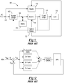
- Fig. 1 is a basic block diagram of an example of a prior art uninterruptible power supply (“UPS") system 100.
- UPS system 100 includes a rectifier/charger 102, a battery 104, a DC bus 106, an inverter 108, a bypass switch 110, a control module 112, and an output transformer 114. It should be understood that some UPS systems do not include an output transformer, and that the source of back-up DC power may be other than a battery, in which case rectifier/charger 102 would not include a charger. It should also be understood that rectifier/charger 102 may only include the rectifier and UPS system 100 have a separate charger.
- UPS system 100 When UPS system 100 is operating in a double conversion mode, alternating current (“AC") power is supplied at an input 116 of UPS system 100.
- Rectifier/charger 102 converts the incoming AC power to direct current (“DC") power. This DC power is supplied to battery 104 to charge the battery. The DC power is also supplied to the DC bus 106 which is coupled to an input of inverter 108.
- Inverter 108 converts the DC power to AC output power that is then supplied to a load 118 via the output transformer 114. If the normal AC power source fails, battery 104 provides power to the DC bus 106 which is converted by inverter 108 to AC output power. In some cases, UPS system 100 is switched to a bypass mode where bypass switch 110 is closed.
- UPS system 100 may be switched to the bypass mode when a component of UPS system 100 in the double conversion power flow path fails, such as rectifier/charger 102 or inverter 108, or when the quality of AC power source is sufficient that it can be used to directly power load 118 without being conditioned through the double conversion path.
- a component of UPS system 100 in the double conversion power flow path fails, such as rectifier/charger 102 or inverter 108, or when the quality of AC power source is sufficient that it can be used to directly power load 118 without being conditioned through the double conversion path.
- Control module 112 controls the rectifier/charger 102, inverter 108, and bypass switch 110. Control module 112 monitors the input and output voltages and currents and controls the rectifier/charger 102 to charge the battery and regulate the DC power including the bus voltage and also controls inverter 108 to regulate the AC output power including the AC voltage.
- a simple repetitive controller for UPS systems is a good controller for harmonic rejection with various loads, especially for nonlinear loads.
- an inherent disadvantage of repetitive control is that it can't provide fast, sub-cycle response, which is one of the most important features of UPS systems to not only maintain a nice sinusoidal voltage, but also provide fast transient responses.
- Another disadvantage of repetitive control is that it's difficult to stabilize without sacrificing the steady state voltage performance.
- Repetitive control is a control method specifically used in dealing with periodic signals. It uses the periodicity of the reference or disturbance to provide a good harmonic rejection.
- Q(Z) is a constant gain smaller than 1
- N is the number of samples per cycle at a fixed sample rate
- S(Z) is a compensator
- Kopt is the optimized gain for the best transient and steady state performance of the control loop.
- k is the kth number of all samples in a sampling period T.
- the gain Q(Z) shown in Equation 1 above is the key to stabilizing a repetitive controller.
- Q(Z) must be smaller than 1 and the smaller the gain, the more stable the controller is with various types of load.
- the smaller the Q(Z) gain the less accurate the steady state controller's performance is. So it's difficult to have a robust stable repetitive controller for various types of load without sacrificing the steady state controller's performance.
- US 6466465 B1 refers to problems of stability and response times for fluctuating loads in implementing a repetitive controller to control an inverter in an uninterruptable power supply, and proposes the use of an alternative control strategy to avoid these problems using computed control values based on temporally separated samples of an output signal to derive a pulse width modulated inverter output.
- a repetitive servomechanism controller for a UPS system has an inner control loop and an outer control loop.
- the inner control loop regulates inverter current and the outer control loop regulates inverter voltage.
- the outer control loop includes a repetitive controller in combination with a harmonic servomechanism controller and a feed-forward controller.
- the inner control loop controls output current of an inverter of the uninterruptible power supply system using a discrete sliding mode current controller of the inner control loop with a PWM voltage signal generated at an output of the discrete sliding mode current controller which is coupled to a PWM drive signal generator that generates PWM drive signals for controlling semiconductor switching devices of the inverter with the PWM drive signals each having a duty cycle determined by a level of the PWM voltage signal.
- the outer control loop includes an output summer having inputs coupled to respective outputs of each of the feed-forward controller, the repetitive controller and the servomechanism controller. An output of the output summer is coupled to an input of the inner control loop. An input summer sums an output voltage of the inverter and a reference voltage to generate an error signal that is provided to an input of the repetitive controller and to an input of the servomechanism controller.
- the feed-forward controller has an input which receives the reference voltage.
- the repetitive controller is configured to eliminate all harmonics and a frequency compensator of the servomechanism controller is configured as a compensator of only fundamental frequency.
- a repetitive controller having the transfer function of Equation 1 above is combined with the harmonic servomechanism controller described in US Patent No. 6,917,124 for "Uninterruptible Power Supply," Figs. 26 - Fig. 33 and accompanying description in particular.
- the entire disclosure of US 6,917,124 is incorporated by reference.
- a servomechanism (sometimes shortened to servo) controller as that term is used herein is an automatic controller that uses error-sensing negative feedback to correct the performance of the device being controlled.)
- One advantage of this harmonic servomechanism controller is that it is easier to stabilize than repetitive controllers.
- Fig. 2 is a simplified block diagram of the harmonic servomechanism controller shown in Figs. 32 and 33 of US 6,917,124 .
- Fig. 3 is a block diagram of a modification of this harmonic servomechanism controller in accordance with an aspect of the present disclosure so that the frequency compensator of this modified harmonic servomechanism controller is a compensator of fundamental frequency only. In Fig. 3 , there are two lines of equations.
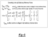
- the first line is for the Q axis and the second line is for the D axis, where the Q and D axes are the result of abc three phase converted to the dq0 stationary reference frame.
- Fig. 5 shows the conversion equation for converting abc three phase to the dq0 reference frame.
- the D and Q axis utilize the same equations, so what follows are definitions for generic parameters and applicable to the equations of both the D and Q axes.
- Vref"(k) is the reference voltage command at sample k
- Vload"(k) is the load voltage measurement at sample k
- the equation in the harmonic servo compensator block is the state space equation for the servo controller.
- Xservo(k) is calculated by solving this state space equation.
- Kq1, Kq2, Kd1 and Kd2 are the gains for the servo controller and are based on tuning results.
- Xplant(k) is the array of measured voltages and currents at sample k. Vinv(k) is measured inverter voltage (or load voltage) at sample k, linv(k) is measured inverter current at sample k, Iload(k) is measured load current at sample k, Vpwm(k) is the PWM voltage command at sample k. Icmd is the current command generated from the servo voltage controller. Note the Xplant(k) can vary depends on what kind electrical components the controlled system has, for example, if the system has an output transformer.
- a repetitive controller having the transfer function of Equation 1 is combined with the harmonic servomechanism controller of Fig. 3 together along with a feed-forward controller to improve transient response. Doing so provides a robust and reliable servomechanism controller that not only provide fast transient response, but also a nice steady state sine-wave output.
- Fig. 4 is a block diagram of a repetitive servomechanism controller 400 in accordance with an aspect of the present disclosure.
- This repetitive servomechanism controller has two control loops - an outer control loop 402 and an inner control loop 404.
- Outer control loop 402 includes an input summer 406, a feed-forward controller 408, a repetitive controller 410, a harmonic servomechanism controller 412, an output summer 414 and a current limiter 416.
- Inner control loop 404 includes an input summer 418, a sliding mode current controller 420 and a PWM drive signal generator 422.
- input summer 406 has a reference signal input 426 at which a reference signal (Vref) is provided and a feedback signal input 428 coupled to a voltage output of inverter 424 (plant G(Z) in Fig. 4 ).
- Reference signal (Vref) is also provided to an input 430 of feed-forward controller 408 and an output 432 of feed-forward controller 408 is provided to an input 434 of output summer 414.
- An output 436 of input summer 406 at which an error signal (Verr) is generated by input summer 406 is coupled to an input 438 of repetitive controller 410 and to an input of harmonic servomechanism controller 412.
- An output 442 of repetitive controller 410 is coupled to an input 446 of output summer 414 and an output 444 of harmonic servomechanism controller 412 is coupled to an input 448 of output summer 414.
- Output summer 414 has an output 450 which provides the output of outer control loop 402 which is coupled through current limiter 416 to a reference input 452 of input summer 418 of inner control loop 404 and reference input 452 provides the input of inner control loop 404.
- a feedback signal input 454 of input summer 418 receives a current feedback signal from inverter 424.
- An output 456 of input summer 418 is coupled to an input 458 of sliding mode current controller 420 and an output 460 of sliding mode current controller 420 is coupled to an input 462 of PWM drive signal generator 422.
- An output (or outputs) 464 of PWM drive signal generator 422 at which PWM drive signals are generated to control the switching of the power semiconductor switching devices (not shown in Fig. 4 ) of inverter 424 are coupled to switching control inputs 466 of these power semiconductor switching devices of inverter 424.
- the inner control loop 404 regulates inverter current using a discrete sliding mode current controller, the same as the discrete sliding mode current controller disclosed in US 6,917,124 , Fig. 27 and accompanying description in particular.
- the inner control loop 404 provides fast transient response. It is useful in limiting inverter current in a timely manner to prevent inverter damage by an overload condition.
- the sliding mode current controller 420 also has zero overshoot, which improves response to load transients.
- the outer control loop 402 regulates the inverter voltage using the above discussed repetitive controller 410 having the transfer function of Equation 1 combined with the above discussed harmonic servomechanism controller 412 and feed-forward controller 408.
- the repetitive controller 410, harmonic servomechanism controller 412 and feed-forward controller 408 are arranged in parallel (with the exception that the Vout feedback is not provided to the feed-forward controller 408), as shown in Fig. 4 .
- the repetitive controller 410 works together with the harmonic servomechanism controller 412 to provide superior harmonic rejection, providing accurate steady state performance and also providing an easier to stabilize controller.
- the feed-forward controller 408 together with the sliding mode current controller 420 provides fast transient response and current limit for UPS system protection. It should be understood that the repetitive servomechanism controller 400 shown in Fig. 4 is an improvement to the servomechanism controller shown in Fig. 27 of US 6,917,124 .
- the repetitive servomechanism controller 400 in accordance with above described aspects of the present disclosure provides not only superior harmonic rejection capability, but also better and faster transient performance and more accurate steady state performance.
- the combination of the repetitive controller 410 with the harmonic servomechanism controller 412 improves the UPS system's output waveform performance, overcoming the disadvantages of the two individual controllers and yields a superior hybrid controller with more robust and reliable performance.
- this repetitive servomechanism controller is easier to stabilize with various types of load.
- the repetitive servomechanism controller 400 may illustratively be implemented in the control module for the USP system, such as control module 112 ( Fig. 1 ).
- the control module may for example be or include a digital processor (DSP) or microprocessor which are programmed with software implementing the repetitive servomechanism controller.
- DSP digital processor
- microprocessor which are programmed with software implementing the repetitive servomechanism controller.
- FPGA Field Programmable Gate Array
- CPLD complex programmable logic device
- ASIC application specific integrated circuit
Landscapes
- Engineering & Computer Science (AREA)
- Power Engineering (AREA)
- Business, Economics & Management (AREA)
- Emergency Management (AREA)
- Inverter Devices (AREA)
Claims (6)
- Steuerung eines unterbrechungsfreien Leistungsversorgungssystems mit Wiederholungsservomechanismus (400), umfassend:eine innere Steuerschleife (404), die einen Ausgangsstrom eines Wechselrichters (424) des unterbrechungsfreien Leistungsversorgungssystems unter Verwendung einer diskreten Gleitmodus-Stromsteuerung (420) der inneren Steuerschleife mit einem PWM-Spannungssignal (Vpwm), erzeugt an einem Ausgang (460) der diskreten Gleitmodus-Stromsteuerung, der an einem PWM-Treibersignalgenerator (422) gekoppelt ist, der PWM-Treibersignale zum Steuern von HalbleiterSchaltvorrichtungen des Wechselrichters erzeugt, steuert, wobei die PWM-Treibersignale jeweils eine durch einen Pegel des PWM-Spannungssignals bestimmte Einschaltdauer aufweisen; undeine äußere Steuerschleife (402), die eine Ausgangsspannung (VOut) des Wechselrichters steuert, die äußere Steuerschleife enthaltend eine vorwärtsgekoppelte Steuerung (408), eine Wiederholungssteuerung (410) und eine Oberschwingung-Servomechanismussteuerung (412), einen Eingangssummierer (406) und einen Ausgangssummierer (414), wobei der Ausgangssummierer an jeweilige Ausgänge (432; 442; 444) jeder der vorwärtsgekoppelten Steuerung, der Wiederholungssteuerung und der Oberschwingung-Servomechanismussteuerung gekoppelte Eingänge (434; 446; 448) aufweist, ein Ausgang (450) des Ausgangssummierers an einen Eingang der inneren Steuerschleife gekoppelt ist, der Eingangssummierer die Ausgangsspannung des Wechselrichters und eine Referenzspannung (VRef) summiert, um ein Fehlersignal (VErr) zu erzeugen, das einem Eingang (438) der Wiederholungssteuerung und einem Eingang der Oberschwingung-Servomechanismussteuerung bereitgestellt wird; und die vorwärtsgekoppelte Steuerung einen Eingang (430) aufweist, der die Referenzspannung empfängt.
- Steuerung eines unterbrechungsfreien Leistungsversorgungssystems mit Wiederholungsservomechanismus nach Anspruch 1, wobei die Wiederholungssteuerung konfiguriert ist, alle Oberschwingungen zu eliminieren, und ein Frequenzkompensator der Oberschwingung-Servomechanismussteuerung als ein Kompensator nur der Grundfrequenz konfiguriert ist.
- Steuerung eines unterbrechungsfreien Leistungsversorgungssystems mit Wiederholungsservomechanismus nach Anspruch 2, wobei die Wiederholungssteuerung konfiguriert ist, alle Oberschwingungen zu eliminieren, indem sie eine Transferfunktion aufweist, definiert durch eine Gleichung RPC(Z)=Z^(-(N-k))/(1-[Q(Z)·Z]^(-N))*Kopt*S(Z)*Z^(-k), wobei Q(Z) eine konstante Verstärkung kleiner als 1 ist, N eine Anzahl von Abtastungen pro Zyklus bei einer festen Abtastrate ist, S(Z) ein Kompensator ist, Kopt eine optimierte Verstärkung für beste Übergangs- und stationäre Leistung der Steuerschleife der Wiederholungssteuerung ist, Z ein Symbol für Z-Transformation ist, Z=ejwt , mit w=2*π*T, T=1/fs eine Abtastperiode ist und fs eine Abtastrate ist und k eine k-te Anzahl aller Abtastungen in einer Abtastperiode T ist.
- Verfahren zum Steuern einer Steuerung eines unterbrechungsfreien Leistungsversorgungssystems mit einem Wiederholungsservomechanismus (400), die eine innere Steuerschleife (404) und eine äußere Steuerschleife (402) aufweist, umfassend:Steuern eines Ausgangsstroms eines Wechselrichters (424) des unterbrechungsfreien Leistungsversorgungssystems mit der inneren Steuerschleife unter Verwendung einer diskreten Gleitmodus-Stromsteuerung (420) der inneren Steuerschleife zum Erzeugen eines PWM-Spannungssignals (Vpwm) an einem Ausgang (460) der diskreten Gleitmodus-Stromsteuerung, der an einem PWM-Treibersignalgenerator (422) gekoppelt ist, und Erzeugen, mit der PWM-Treibersignalsteuerung, von PWM-Treibersignalen, die eine durch einen Pegel der PWM-Spannungssignale bestimmte Einschaltdauer aufweisen, und Steuern von Halbleiterschaltvorrichtungen des Wechselrichters mit den PWM-Treibersignalen;Steuern einer Ausgangsspannung (VOut) des Wechselrichters mit der äußeren Steuerschleife durch Erzeugen eines Ausgangssignals durch Summieren, mit einem Ausgangssummierer (414), von Ausgängen jeder einer vorwärtsgekoppelten Steuerung (408), einer Wiederholungssteuerung (410) und einer Oberschwingung-Servomechanismussteuerung (412) der äußeren Steuerschleife und Bereitstellen des Ausgangssignals einem Eingang (452) der inneren Steuerschleife;Bereitstellen einer Referenzspannung (VRef) einem Eingang (430) der vorwärtsgekoppelten Steuerung; undErzeugen eines Fehlersignals (VErr) durch Summieren, mit einem Eingangssummierer, einer Ausgangsspannung (VOut) des Wechselrichters und der Referenzspannung und Bereitstellen eines Fehlersignals einem Eingang (438) der Wiederholungssteuerung und einem Eingang (440) der Oberschwingung-Servomechanismussteuerung.
- Verfahren nach Anspruch 4, enthaltend Eliminieren aller Oberschwingungen und Kompensieren nur der Grundfrequenz mit einem Frequenzkompensator der Oberschwingung-Servomechanismussteuerung.
- Verfahren nach Anspruch 5, wobei Eliminieren aller Oberschwingungen mit der Wiederholungssteuerung enthält, eine Transferfunktion der Wiederholungssteuerung aufzuweisen, definiert durch eine Gleichung RPC(Z)=Z^(-(N-k))/(1-[Q(Z)·Z]^(-N))*Kopt*S(Z)*Z^(-k) wobei Q(Z) eine konstante Verstärkung kleiner als 1 ist, N eine Anzahl von Abtastungen pro Zyklus bei einer festen Abtastrate ist, S(Z) ein Kompensator ist, Kopt eine optimierte Verstärkung für beste Übergangs- und stationäre Leistung der Steuerschleife der Wiederholungssteuerung ist, Z ein Symbol für Z-Transformation ist, Z=ejwt , mit w=2*π*T, T=1/fs eine Abtastperiode ist und fs eine Abtastrate ist und k eine k-te Anzahl aller Abtastungen in einer Abtastperiode T ist.
Applications Claiming Priority (3)
| Application Number | Priority Date | Filing Date | Title |
|---|---|---|---|
| US201361911600P | 2013-12-04 | 2013-12-04 | |
| US14/541,667 US9270160B2 (en) | 2013-12-04 | 2014-11-14 | Repetitive servomechanism controller for uninterruptible power supply system |
| PCT/US2014/065915 WO2015084571A1 (en) | 2013-12-04 | 2014-11-17 | Repetitive servomechanism controller for uninterruptible power supply system |
Publications (2)
| Publication Number | Publication Date |
|---|---|
| EP3078096A1 EP3078096A1 (de) | 2016-10-12 |
| EP3078096B1 true EP3078096B1 (de) | 2018-01-10 |
Family
ID=53266146
Family Applications (1)
| Application Number | Title | Priority Date | Filing Date |
|---|---|---|---|
| EP14805465.3A Active EP3078096B1 (de) | 2013-12-04 | 2014-11-17 | Repetitive servomechanismussteuerung für unterbrechungsfreies stromversorgungssystem |
Country Status (4)
| Country | Link |
|---|---|
| US (1) | US9270160B2 (de) |
| EP (1) | EP3078096B1 (de) |
| CN (1) | CN105850016B (de) |
| WO (1) | WO2015084571A1 (de) |
Families Citing this family (7)
| Publication number | Priority date | Publication date | Assignee | Title |
|---|---|---|---|---|
| US9531288B2 (en) * | 2012-11-21 | 2016-12-27 | Liebert Corporation | Systems and methods for balancing UPS output voltages during transitions between operating modes |
| CN105159063A (zh) * | 2015-08-31 | 2015-12-16 | 南京航空航天大学 | 一种分数相位超前补偿重复控制器及控制方法 |
| CN105159062A (zh) * | 2015-08-31 | 2015-12-16 | 南京航空航天大学 | 一种基于插入式快速重复控制器的复合控制方法及系统 |
| EP3171235B1 (de) * | 2015-11-19 | 2020-04-29 | Omron Corporation | Steuerungsvorrichtung, steuerungsverfahren, informationsverarbeitungsprogramm und aufzeichnungsmedium |
| JP6531682B2 (ja) * | 2016-03-11 | 2019-06-19 | オムロン株式会社 | モータ制御装置、モータ制御方法、プログラム、および記録媒体 |
| RU187219U1 (ru) * | 2018-06-05 | 2019-02-25 | Акционерное общество "Электромаш" | Устройство стабилизации напряжения с инвертором для подвижного состава |
| CN114362578B (zh) * | 2021-12-30 | 2022-07-29 | 深圳市首航新能源股份有限公司 | 一种并网逆变器并网控制方法、控制器以及并网逆变器 |
Family Cites Families (7)
| Publication number | Priority date | Publication date | Assignee | Title |
|---|---|---|---|---|
| US6466465B1 (en) | 2000-02-14 | 2002-10-15 | Liebert Corporation | Digital control of voltage harmonic distortion and overload current protection for inverters |
| US6917124B2 (en) * | 2000-10-27 | 2005-07-12 | Liebert Corporation | Uninterruptible power supply |
| CN101976042B (zh) * | 2010-09-09 | 2014-12-03 | 浙江工业大学 | 适用于周期伺服系统的离散滑模重复控制方法 |
| US9018870B2 (en) * | 2011-03-25 | 2015-04-28 | Aisin Aw Co., Ltd. | Control device |
| EP2634909B1 (de) * | 2012-03-02 | 2017-02-15 | ABB Research Ltd. | Verfahren zur Steuerung einer netzgekoppelten Hochsetz-Tiefsetz-Stromzwischenkreis- Vollbrücken-Kaskade für Photovoltaic Anwendunden und Vorrichtung |
| US9878738B2 (en) * | 2012-03-28 | 2018-01-30 | Robert Bosch Gmbh | Non-linear compensation controller for active steering system in a vehicle |
| CN103401243B (zh) * | 2013-07-26 | 2015-10-28 | 徐州中矿大传动与自动化有限公司 | 一种指定次谐波补偿apf的谐波检测和控制方法 |
-
2014
- 2014-11-14 US US14/541,667 patent/US9270160B2/en active Active
- 2014-11-17 EP EP14805465.3A patent/EP3078096B1/de active Active
- 2014-11-17 WO PCT/US2014/065915 patent/WO2015084571A1/en not_active Ceased
- 2014-11-17 CN CN201480065788.2A patent/CN105850016B/zh active Active
Also Published As
| Publication number | Publication date |
|---|---|
| US9270160B2 (en) | 2016-02-23 |
| WO2015084571A1 (en) | 2015-06-11 |
| CN105850016A (zh) | 2016-08-10 |
| US20150155793A1 (en) | 2015-06-04 |
| CN105850016B (zh) | 2018-10-02 |
| EP3078096A1 (de) | 2016-10-12 |
Similar Documents
| Publication | Publication Date | Title |
|---|---|---|
| EP3078096B1 (de) | Repetitive servomechanismussteuerung für unterbrechungsfreies stromversorgungssystem | |
| EP3447882B1 (de) | Inverter-parallelierungs-steuerungssystem und verfahren | |
| Segaran et al. | Enhanced load step response for a bidirectional DC–DC converter | |
| Li et al. | Model predictive control of a voltage-source inverter with seamless transition between islanded and grid-connected operations | |
| Mattavelli et al. | Analysis of control-delay reduction for the improvement of UPS voltage-loop bandwidth | |
| EP2523329B1 (de) | Spannungsgesteuerte Stromquelle zur Spannungsregelung | |
| EP3382882A1 (de) | Mehrfachstatus-pwm-befehl für dreistufige wechselrichter | |
| Heyderi et al. | Model predictive control approach for distributed hierarchical control of vsc-based microgrids | |
| Awad et al. | Invariant-set design of robust switched trackers for bidirectional power converters in hybrid microgrids | |
| MS | An improved robust coupled sliding mode control strategy for solar photovoltaic‐based single‐phase inverters. | |
| EP3247018A1 (de) | Steuerungsvorrichtung für einen wechselrichter | |
| Elthokaby et al. | Finite-control set model-predictive control for single-phase voltage-source UPS inverters | |
| Li et al. | Model predictive decoupled power control for single-phase grid-tied inverter | |
| Muhammad et al. | Modelling and control of non-isolated high voltage gain boost converter employing coupled inductor and switched capacitor | |
| US20120113691A1 (en) | Power converter with controlled current source | |
| Prabhakaran et al. | A novel PR controller with improved performance for single-phase UPS inverter | |
| JP6025663B2 (ja) | 無停電電源装置 | |
| Pawar et al. | MPC based controller for dual active bidirectional DC-DC converter driving inverter using dynamic phasor approach | |
| JP2015109781A (ja) | 系統連系電力変換装置 | |
| CA2865612C (en) | Dc-bus controller for an inverter | |
| TK | Integrated predictive control and fault diagnosis algorithm for single inductor-based DC-DC converters for photovoltaic systems | |
| Li et al. | A harmonic constrained minimum energy controller for a single-phase grid-tied inverter using model predictive control | |
| Buso et al. | Comparison of oversampled current controllers for microgrid utility interface converters | |
| Rajeshkanna et al. | A single-phase grid-connected PV cell system based on a boost-inverter | |
| Abouloifa et al. | Adaptive Nonlinear Control of Single-Phase Inverters for UPS Applications: Average Performance Analysis |
Legal Events
| Date | Code | Title | Description |
|---|---|---|---|
| PUAI | Public reference made under article 153(3) epc to a published international application that has entered the european phase |
Free format text: ORIGINAL CODE: 0009012 |
|
| 17P | Request for examination filed |
Effective date: 20160524 |
|
| AK | Designated contracting states |
Kind code of ref document: A1 Designated state(s): AL AT BE BG CH CY CZ DE DK EE ES FI FR GB GR HR HU IE IS IT LI LT LU LV MC MK MT NL NO PL PT RO RS SE SI SK SM TR |
|
| AX | Request for extension of the european patent |
Extension state: BA ME |
|
| DAX | Request for extension of the european patent (deleted) | ||
| GRAP | Despatch of communication of intention to grant a patent |
Free format text: ORIGINAL CODE: EPIDOSNIGR1 |
|
| RIC1 | Information provided on ipc code assigned before grant |
Ipc: H02M 7/537 20060101ALI20170601BHEP Ipc: H02M 7/5387 20070101ALI20170601BHEP Ipc: H02J 9/00 20060101AFI20170601BHEP Ipc: H02M 1/12 20060101ALI20170601BHEP |
|
| INTG | Intention to grant announced |
Effective date: 20170623 |
|
| GRAS | Grant fee paid |
Free format text: ORIGINAL CODE: EPIDOSNIGR3 |
|
| GRAA | (expected) grant |
Free format text: ORIGINAL CODE: 0009210 |
|
| AK | Designated contracting states |
Kind code of ref document: B1 Designated state(s): AL AT BE BG CH CY CZ DE DK EE ES FI FR GB GR HR HU IE IS IT LI LT LU LV MC MK MT NL NO PL PT RO RS SE SI SK SM TR |
|
| REG | Reference to a national code |
Ref country code: CH Ref legal event code: EP Ref country code: AT Ref legal event code: REF Ref document number: 963449 Country of ref document: AT Kind code of ref document: T Effective date: 20180115 |
|
| REG | Reference to a national code |
Ref country code: IE Ref legal event code: FG4D |
|
| REG | Reference to a national code |
Ref country code: DE Ref legal event code: R096 Ref document number: 602014019898 Country of ref document: DE |
|
| REG | Reference to a national code |
Ref country code: NL Ref legal event code: MP Effective date: 20180110 |
|
| REG | Reference to a national code |
Ref country code: AT Ref legal event code: MK05 Ref document number: 963449 Country of ref document: AT Kind code of ref document: T Effective date: 20180110 |
|
| PG25 | Lapsed in a contracting state [announced via postgrant information from national office to epo] |
Ref country code: NL Free format text: LAPSE BECAUSE OF FAILURE TO SUBMIT A TRANSLATION OF THE DESCRIPTION OR TO PAY THE FEE WITHIN THE PRESCRIBED TIME-LIMIT Effective date: 20180110 |
|
| PG25 | Lapsed in a contracting state [announced via postgrant information from national office to epo] |
Ref country code: FI Free format text: LAPSE BECAUSE OF FAILURE TO SUBMIT A TRANSLATION OF THE DESCRIPTION OR TO PAY THE FEE WITHIN THE PRESCRIBED TIME-LIMIT Effective date: 20180110 Ref country code: NO Free format text: LAPSE BECAUSE OF FAILURE TO SUBMIT A TRANSLATION OF THE DESCRIPTION OR TO PAY THE FEE WITHIN THE PRESCRIBED TIME-LIMIT Effective date: 20180410 Ref country code: LT Free format text: LAPSE BECAUSE OF FAILURE TO SUBMIT A TRANSLATION OF THE DESCRIPTION OR TO PAY THE FEE WITHIN THE PRESCRIBED TIME-LIMIT Effective date: 20180110 Ref country code: HR Free format text: LAPSE BECAUSE OF FAILURE TO SUBMIT A TRANSLATION OF THE DESCRIPTION OR TO PAY THE FEE WITHIN THE PRESCRIBED TIME-LIMIT Effective date: 20180110 Ref country code: ES Free format text: LAPSE BECAUSE OF FAILURE TO SUBMIT A TRANSLATION OF THE DESCRIPTION OR TO PAY THE FEE WITHIN THE PRESCRIBED TIME-LIMIT Effective date: 20180110 Ref country code: CY Free format text: LAPSE BECAUSE OF FAILURE TO SUBMIT A TRANSLATION OF THE DESCRIPTION OR TO PAY THE FEE WITHIN THE PRESCRIBED TIME-LIMIT Effective date: 20180110 |
|
| PG25 | Lapsed in a contracting state [announced via postgrant information from national office to epo] |
Ref country code: GR Free format text: LAPSE BECAUSE OF FAILURE TO SUBMIT A TRANSLATION OF THE DESCRIPTION OR TO PAY THE FEE WITHIN THE PRESCRIBED TIME-LIMIT Effective date: 20180411 Ref country code: IS Free format text: LAPSE BECAUSE OF FAILURE TO SUBMIT A TRANSLATION OF THE DESCRIPTION OR TO PAY THE FEE WITHIN THE PRESCRIBED TIME-LIMIT Effective date: 20180510 Ref country code: PL Free format text: LAPSE BECAUSE OF FAILURE TO SUBMIT A TRANSLATION OF THE DESCRIPTION OR TO PAY THE FEE WITHIN THE PRESCRIBED TIME-LIMIT Effective date: 20180110 Ref country code: LV Free format text: LAPSE BECAUSE OF FAILURE TO SUBMIT A TRANSLATION OF THE DESCRIPTION OR TO PAY THE FEE WITHIN THE PRESCRIBED TIME-LIMIT Effective date: 20180110 Ref country code: SE Free format text: LAPSE BECAUSE OF FAILURE TO SUBMIT A TRANSLATION OF THE DESCRIPTION OR TO PAY THE FEE WITHIN THE PRESCRIBED TIME-LIMIT Effective date: 20180110 Ref country code: RS Free format text: LAPSE BECAUSE OF FAILURE TO SUBMIT A TRANSLATION OF THE DESCRIPTION OR TO PAY THE FEE WITHIN THE PRESCRIBED TIME-LIMIT Effective date: 20180110 Ref country code: AT Free format text: LAPSE BECAUSE OF FAILURE TO SUBMIT A TRANSLATION OF THE DESCRIPTION OR TO PAY THE FEE WITHIN THE PRESCRIBED TIME-LIMIT Effective date: 20180110 Ref country code: BG Free format text: LAPSE BECAUSE OF FAILURE TO SUBMIT A TRANSLATION OF THE DESCRIPTION OR TO PAY THE FEE WITHIN THE PRESCRIBED TIME-LIMIT Effective date: 20180410 |
|
| REG | Reference to a national code |
Ref country code: DE Ref legal event code: R097 Ref document number: 602014019898 Country of ref document: DE |
|
| PG25 | Lapsed in a contracting state [announced via postgrant information from national office to epo] |
Ref country code: EE Free format text: LAPSE BECAUSE OF FAILURE TO SUBMIT A TRANSLATION OF THE DESCRIPTION OR TO PAY THE FEE WITHIN THE PRESCRIBED TIME-LIMIT Effective date: 20180110 Ref country code: AL Free format text: LAPSE BECAUSE OF FAILURE TO SUBMIT A TRANSLATION OF THE DESCRIPTION OR TO PAY THE FEE WITHIN THE PRESCRIBED TIME-LIMIT Effective date: 20180110 |
|
| RAP2 | Party data changed (patent owner data changed or rights of a patent transferred) |
Owner name: VERTIV CORPORATION |
|
| PLBE | No opposition filed within time limit |
Free format text: ORIGINAL CODE: 0009261 |
|
| STAA | Information on the status of an ep patent application or granted ep patent |
Free format text: STATUS: NO OPPOSITION FILED WITHIN TIME LIMIT |
|
| PG25 | Lapsed in a contracting state [announced via postgrant information from national office to epo] |
Ref country code: CZ Free format text: LAPSE BECAUSE OF FAILURE TO SUBMIT A TRANSLATION OF THE DESCRIPTION OR TO PAY THE FEE WITHIN THE PRESCRIBED TIME-LIMIT Effective date: 20180110 Ref country code: DK Free format text: LAPSE BECAUSE OF FAILURE TO SUBMIT A TRANSLATION OF THE DESCRIPTION OR TO PAY THE FEE WITHIN THE PRESCRIBED TIME-LIMIT Effective date: 20180110 Ref country code: SM Free format text: LAPSE BECAUSE OF FAILURE TO SUBMIT A TRANSLATION OF THE DESCRIPTION OR TO PAY THE FEE WITHIN THE PRESCRIBED TIME-LIMIT Effective date: 20180110 Ref country code: SK Free format text: LAPSE BECAUSE OF FAILURE TO SUBMIT A TRANSLATION OF THE DESCRIPTION OR TO PAY THE FEE WITHIN THE PRESCRIBED TIME-LIMIT Effective date: 20180110 |
|
| 26N | No opposition filed |
Effective date: 20181011 |
|
| REG | Reference to a national code |
Ref country code: DE Ref legal event code: R081 Ref document number: 602014019898 Country of ref document: DE Owner name: VERTIV CORPORATION, COLUMBUS, US Free format text: FORMER OWNER: LIEBERT CORPORATION, COLUMBUS, OHIO, US |
|
| PG25 | Lapsed in a contracting state [announced via postgrant information from national office to epo] |
Ref country code: SI Free format text: LAPSE BECAUSE OF FAILURE TO SUBMIT A TRANSLATION OF THE DESCRIPTION OR TO PAY THE FEE WITHIN THE PRESCRIBED TIME-LIMIT Effective date: 20180110 |
|
| REG | Reference to a national code |
Ref country code: CH Ref legal event code: PL |
|
| PG25 | Lapsed in a contracting state [announced via postgrant information from national office to epo] |
Ref country code: MC Free format text: LAPSE BECAUSE OF FAILURE TO SUBMIT A TRANSLATION OF THE DESCRIPTION OR TO PAY THE FEE WITHIN THE PRESCRIBED TIME-LIMIT Effective date: 20180110 Ref country code: LU Free format text: LAPSE BECAUSE OF NON-PAYMENT OF DUE FEES Effective date: 20181117 |
|
| REG | Reference to a national code |
Ref country code: BE Ref legal event code: MM Effective date: 20181130 |
|
| REG | Reference to a national code |
Ref country code: IE Ref legal event code: MM4A |
|
| PG25 | Lapsed in a contracting state [announced via postgrant information from national office to epo] |
Ref country code: LI Free format text: LAPSE BECAUSE OF NON-PAYMENT OF DUE FEES Effective date: 20181130 Ref country code: CH Free format text: LAPSE BECAUSE OF NON-PAYMENT OF DUE FEES Effective date: 20181130 |
|
| PG25 | Lapsed in a contracting state [announced via postgrant information from national office to epo] |
Ref country code: IE Free format text: LAPSE BECAUSE OF NON-PAYMENT OF DUE FEES Effective date: 20181117 |
|
| PG25 | Lapsed in a contracting state [announced via postgrant information from national office to epo] |
Ref country code: BE Free format text: LAPSE BECAUSE OF NON-PAYMENT OF DUE FEES Effective date: 20181130 |
|
| PG25 | Lapsed in a contracting state [announced via postgrant information from national office to epo] |
Ref country code: MT Free format text: LAPSE BECAUSE OF NON-PAYMENT OF DUE FEES Effective date: 20181117 |
|
| PG25 | Lapsed in a contracting state [announced via postgrant information from national office to epo] |
Ref country code: TR Free format text: LAPSE BECAUSE OF FAILURE TO SUBMIT A TRANSLATION OF THE DESCRIPTION OR TO PAY THE FEE WITHIN THE PRESCRIBED TIME-LIMIT Effective date: 20180110 |
|
| PG25 | Lapsed in a contracting state [announced via postgrant information from national office to epo] |
Ref country code: PT Free format text: LAPSE BECAUSE OF FAILURE TO SUBMIT A TRANSLATION OF THE DESCRIPTION OR TO PAY THE FEE WITHIN THE PRESCRIBED TIME-LIMIT Effective date: 20180110 |
|
| PG25 | Lapsed in a contracting state [announced via postgrant information from national office to epo] |
Ref country code: RO Free format text: LAPSE BECAUSE OF FAILURE TO SUBMIT A TRANSLATION OF THE DESCRIPTION OR TO PAY THE FEE WITHIN THE PRESCRIBED TIME-LIMIT Effective date: 20180110 Ref country code: MK Free format text: LAPSE BECAUSE OF NON-PAYMENT OF DUE FEES Effective date: 20180110 Ref country code: HU Free format text: LAPSE BECAUSE OF FAILURE TO SUBMIT A TRANSLATION OF THE DESCRIPTION OR TO PAY THE FEE WITHIN THE PRESCRIBED TIME-LIMIT; INVALID AB INITIO Effective date: 20141117 |
|
| P01 | Opt-out of the competence of the unified patent court (upc) registered |
Effective date: 20230621 |
|
| PGFP | Annual fee paid to national office [announced via postgrant information from national office to epo] |
Ref country code: DE Payment date: 20251128 Year of fee payment: 12 |
|
| PGFP | Annual fee paid to national office [announced via postgrant information from national office to epo] |
Ref country code: GB Payment date: 20251127 Year of fee payment: 12 |
|
| PGFP | Annual fee paid to national office [announced via postgrant information from national office to epo] |
Ref country code: IT Payment date: 20251119 Year of fee payment: 12 |
|
| PGFP | Annual fee paid to national office [announced via postgrant information from national office to epo] |
Ref country code: FR Payment date: 20251125 Year of fee payment: 12 |