EP3078112B1 - Actionneur avec capteur de position - Google Patents
Actionneur avec capteur de position Download PDFInfo
- Publication number
- EP3078112B1 EP3078112B1 EP15733443.4A EP15733443A EP3078112B1 EP 3078112 B1 EP3078112 B1 EP 3078112B1 EP 15733443 A EP15733443 A EP 15733443A EP 3078112 B1 EP3078112 B1 EP 3078112B1
- Authority
- EP
- European Patent Office
- Prior art keywords
- motor
- voltage
- actuator according
- position sensor
- actuator
- Prior art date
- Legal status (The legal status is an assumption and is not a legal conclusion. Google has not performed a legal analysis and makes no representation as to the accuracy of the status listed.)
- Active
Links
Images

Classifications
-
- H—ELECTRICITY
- H02—GENERATION; CONVERSION OR DISTRIBUTION OF ELECTRIC POWER
- H02K—DYNAMO-ELECTRIC MACHINES
- H02K11/00—Structural association of dynamo-electric machines with electric components or with devices for shielding, monitoring or protection
- H02K11/20—Structural association of dynamo-electric machines with electric components or with devices for shielding, monitoring or protection for measuring, monitoring, testing, protecting or switching
- H02K11/21—Devices for sensing speed or position, or actuated thereby
-
- H—ELECTRICITY
- H02—GENERATION; CONVERSION OR DISTRIBUTION OF ELECTRIC POWER
- H02P—CONTROL OR REGULATION OF ELECTRIC MOTORS, ELECTRIC GENERATORS OR DYNAMO-ELECTRIC CONVERTERS; CONTROLLING TRANSFORMERS, REACTORS OR CHOKE COILS
- H02P6/00—Arrangements for controlling synchronous motors or other dynamo-electric motors using electronic commutation dependent on the rotor position; Electronic commutators therefor
- H02P6/14—Electronic commutators
- H02P6/16—Circuit arrangements for detecting position
-
- H—ELECTRICITY
- H02—GENERATION; CONVERSION OR DISTRIBUTION OF ELECTRIC POWER
- H02P—CONTROL OR REGULATION OF ELECTRIC MOTORS, ELECTRIC GENERATORS OR DYNAMO-ELECTRIC CONVERTERS; CONTROLLING TRANSFORMERS, REACTORS OR CHOKE COILS
- H02P6/00—Arrangements for controlling synchronous motors or other dynamo-electric motors using electronic commutation dependent on the rotor position; Electronic commutators therefor
- H02P6/14—Electronic commutators
-
- H—ELECTRICITY
- H02—GENERATION; CONVERSION OR DISTRIBUTION OF ELECTRIC POWER
- H02P—CONTROL OR REGULATION OF ELECTRIC MOTORS, ELECTRIC GENERATORS OR DYNAMO-ELECTRIC CONVERTERS; CONTROLLING TRANSFORMERS, REACTORS OR CHOKE COILS
- H02P7/00—Arrangements for regulating or controlling the speed or torque of electric DC motors
- H02P7/06—Arrangements for regulating or controlling the speed or torque of electric DC motors for regulating or controlling an individual DC dynamo-electric motor by varying field or armature current
- H02P7/18—Arrangements for regulating or controlling the speed or torque of electric DC motors for regulating or controlling an individual DC dynamo-electric motor by varying field or armature current by master control with auxiliary power
Definitions
- the present invention relates to an actuator with an electric motor controlled by a control unit and an active electronic position sensor for detecting the actuator position with the features of the preamble of patent claim 1.
- Actuators are used for a wide variety of purposes, for example to operate valves or flaps in motor vehicles.
- the actuators discussed here have an electric motor that is controlled by a control unit, for example engine control electronics (ECU).
- the electric motor can, for example, operate an actuating element, the change in position of which is detected by a position sensor via a transmission.
- a supply voltage is required to operate this position sensor.
- connection circuit for a measuring device in which the adaptation of a voltage supply through the use of a converter is described.
- a device for detecting the movement of a movable part in which the position signals emitted by two position sensors are added to a signal which is fed to an evaluation arrangement via a line.
- the position areas assigned by the position sensors have an overlap area.
- the position signals are assigned different discrete values which can be evaluated in the evaluation arrangement with simple means.
- the DE 10 2008 047 494 A1 discloses an electronically commutated direct current motor, in particular for an electronically controlled brake system, comprising a common electronic controller, with several electrical means, in particular with several Hall sensors for detecting the rotor rotation position and / or for detecting a rotor speed. All electrical means are electrical Supply circuit in the common controller with the help of a series circuit connected to one or more winding phases of the DC motor are electrically supplied.
- the invention is based on the object of providing an actuator of the type described at the outset, which is distinguished by a particularly simple structure.
- the invention uses the already existing control line or supply line of the motor from the control unit provided for supplying the position sensor with electrical energy. Additional lines can therefore be omitted.
- the solution according to the invention provides that at least one motor connection supplies a positive pulsed voltage at periodic intervals by providing a rectifier circuit with a series resistor and storage capacitor behind the tap of the motor connections.
- the connections of the control voltages U M1 and U M2 for the operation of the motor are connected in such a way that when the motor is idling (connections U M1 and / or U M2 are switched to high resistance via transistors) and / or during a motor brake (U M1 and U M2 are switched to the same potential ⁇ short circuit between U M1 and U M2 ) at least one of the two motor connections U M1 , U M2 is connected to a positive voltage U B.
- one embodiment provides that there is a common ground for a bridge circuit for motor control and signal evaluation.
- the output signals of the position sensor remain independent of the supply voltage within a defined range (non-ratiometric.
- An embodiment is particularly preferred which is characterized in that a rectifier circuit with a storage capacitor for generating a filtered DC voltage is arranged behind the tap of the motor connections of the control line from the control unit, which supplies the electronic position sensor with sufficient voltage.
- a series resistor can also be provided here.
- the rectifier circuit can include a bridge circuit.
- a separate ground line is routed to the position sensor, the rectifier circuit having only one half-bridge.
- the rectifier circuit can also consist of active transistors. This results in a smaller voltage drop.
- the invention is also suitable for a brushless motor with two or more terminals.
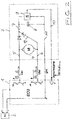
- Figure 1 shows the block diagram of an actuator 3, which is controlled by a control unit (ECU) 1, which is supplied with voltage from a battery 2.
- the actuator 3 has an electric motor 4 which actuates an actuating element (not shown here), the position or change in position of which is detected by a position sensor 9. The corresponding position or change in position is fed from the position sensor 9 in the form of electrical signals via a line 10 to the control unit 1.
- the electric motor 4 is supplied with pulsed voltage via the lines 5, 6 of the control unit 1.
- the supply of the motor 4 is also used to operate the position sensor 9 with electrical energy (direct voltage), so that separate supply lines for operating the sensor 9 can be omitted.
- a rectifier circuit with a series resistor 7 and a storage capacitor 8 is provided behind the tapping of the motor connections. Through this a filtered DC voltage is generated, which supplies the electronic position sensor 9 with sufficient voltage.
- the rectifier circuit has a bridge circuit 13 comprising diodes. It is provided here that at least one connection supplies a positive voltage at periodic intervals and that there is a common ground for the bridge circuit and signal evaluation.
- the connections of the control voltage U M1 and U M2 for operating the motor 4 are connected in such a way that at least one of the two motor connections U M1 , U M2 is connected to a positive voltage U B when the motor is idling and / or during an engine brake.
- the rectifier circuit comprises only one half bridge 12 with diodes.
- the embodiment of the Figure 1 thus represents an actuator feedback system without sensor supply lines in the form of a three-wire concept, while the embodiment of FIG Figure 2 shows such a system in the form of a four-wire concept. In all cases, there is no need for separate feed lines for applying the required supply voltage to the position sensor.
Landscapes
- Engineering & Computer Science (AREA)
- Power Engineering (AREA)
- Microelectronics & Electronic Packaging (AREA)
- Control Of Motors That Do Not Use Commutators (AREA)
- Control Of Direct Current Motors (AREA)
Claims (9)
- Actionneur comprenant un moteur électrique commandé par une unité de commande et un capteur de position électronique actif destiné à détecter la position de l'actionneur, l'énergie électrique destinée au fonctionnement du capteur de position étant prise sur l'unité de commande par le biais des bornes de moteur de la ligne de commande du moteur, les deux bornes de moteur (5, 6) de la tension de commande Um1 et Um2 destinées au fonctionnement du moteur (4) étant commutées de telle sorte qu'au moins une borne de moteur (5, 6) fournit une tension pulsée positive à intervalles périodiques, caractérisé en ce qu'un circuit redresseur pourvu d'une résistance série (7) et d'un condensateur de puissance (8) est prévu en arrière de la prise des bornes de moteur (5, 6), l'une des deux bornes de moteur (5, 6) de la tension de commande Um1 et Um2 étant commutée avec une tension positive UB pendant un ralenti du moteur et l'une au moins des deux bornes de moteur (5, 6) de la tension de commande Um1 et Um2 étant commutée avec une tension positive UB pendant un freinage du moteur.
- Actionneur selon la revendication 1, caractérisé en ce qu'il est prévu une masse commune pour un circuit en pont de la commande de moteur et une évaluation de signal.
- Actionneur selon l'une des revendications 1 et 2, caractérisé en ce que les signaux de sortie du capteur de position (9) restent indépendants de la tension d'alimentation dans une plage spécifiée.
- Actionneur selon l'une des revendications précédentes, caractérisé en ce qu'un circuit redresseur pourvu d'un condensateur de puissance (8) destiné à générer une tension continue filtrée et alimentant le capteur de position électronique (9) avec une tension suffisante est disposé en arrière de la prise des bornes de moteur (5, 6) de la ligne de commande provenant de l'unité de commande (1).
- Actionneur selon la revendication 4, caractérisé en ce qu'une résistance série (7) est également prévue.
- Actionneur selon la revendication 4 ou 5, caractérisé en ce que le circuit redresseur comprend un circuit en pont (13).
- Actionneur selon l'une des revendications 4 à 6, caractérisé en ce qu'une ligne de masse distincte (11) est amenée au capteur de position (9) et en ce que le circuit redresseur ne comporte qu'un demi-pont (12).
- Actionneur selon l'une des revendications 4 à 7, caractérisé en ce que le circuit redresseur comprend des transistors actifs.
- Actionneur selon l'une des revendications précédentes, caractérisé en ce qu'il comporte un moteur sans balais pourvu de deux bornes ou plus.
Applications Claiming Priority (2)
| Application Number | Priority Date | Filing Date | Title |
|---|---|---|---|
| DE102014212804.8A DE102014212804B4 (de) | 2014-07-02 | 2014-07-02 | Aktuator mit Positionssensor |
| PCT/EP2015/064956 WO2016001289A1 (fr) | 2014-07-02 | 2015-07-01 | Actionneur comprenant un capteur de position |
Publications (2)
| Publication Number | Publication Date |
|---|---|
| EP3078112A1 EP3078112A1 (fr) | 2016-10-12 |
| EP3078112B1 true EP3078112B1 (fr) | 2020-10-14 |
Family
ID=53499007
Family Applications (1)
| Application Number | Title | Priority Date | Filing Date |
|---|---|---|---|
| EP15733443.4A Active EP3078112B1 (fr) | 2014-07-02 | 2015-07-01 | Actionneur avec capteur de position |
Country Status (5)
| Country | Link |
|---|---|
| US (1) | US10630148B2 (fr) |
| EP (1) | EP3078112B1 (fr) |
| CN (1) | CN105940602B (fr) |
| DE (1) | DE102014212804B4 (fr) |
| WO (1) | WO2016001289A1 (fr) |
Cited By (1)
| Publication number | Priority date | Publication date | Assignee | Title |
|---|---|---|---|---|
| DE102021111644A1 (de) | 2021-05-05 | 2022-11-10 | Schaeffler Technologies AG & Co. KG | Lenkungsaktuator und Verfahren zur Verarbeitung von Sensorsignalen |
Families Citing this family (4)
| Publication number | Priority date | Publication date | Assignee | Title |
|---|---|---|---|---|
| DE102014212804B4 (de) | 2014-07-02 | 2016-09-15 | Continental Automotive Gmbh | Aktuator mit Positionssensor |
| CN106783011B (zh) * | 2016-12-27 | 2018-05-11 | 宁波市镇海华泰电器厂 | 采用半桥电路的交流电磁铁 |
| CN106783012B (zh) * | 2016-12-27 | 2018-06-19 | 宁波市镇海华泰电器厂 | 高效节电的电磁铁 |
| DE102017105543A1 (de) * | 2017-03-15 | 2018-09-20 | Schaeffler Technologies AG & Co. KG | Verfahren und Vorrichtung zur Beibehaltung einer detektierten Absolutposition eines als Aktor wirkenden Elektromotors in einem kritischen Betriebsfall |
Citations (1)
| Publication number | Priority date | Publication date | Assignee | Title |
|---|---|---|---|---|
| EP2680431A2 (fr) * | 2012-06-29 | 2014-01-01 | Melexis Technologies NV | Procédé et système d'alimentation et de mesure des positions d'une pluralité de moteurs CC via une interface filaire |
Family Cites Families (14)
| Publication number | Priority date | Publication date | Assignee | Title |
|---|---|---|---|---|
| EP0593925B1 (fr) | 1992-10-21 | 1997-12-29 | Robert Bosch Gmbh | Dispositif de détection de mouvement d'une pièce mobile |
| ES2135491T3 (es) * | 1992-10-21 | 1999-11-01 | Bosch Gmbh Robert | Accionamiento electromotor. |
| US5389864A (en) * | 1993-03-29 | 1995-02-14 | Lake Center Industries, Inc. | Actuator with motor and feedback driven by a common power supply |
| JPH0775303A (ja) * | 1993-07-09 | 1995-03-17 | Tamron Co Ltd | アクチュエータ装置及びアクチュエータ |
| DE19527982C2 (de) | 1995-07-31 | 2002-08-22 | Fhp Motors Gmbh | Elektronisch kommutierter Elektromotor |
| US6300736B1 (en) | 1999-04-09 | 2001-10-09 | Melexis Nv | Low pin count DC-motor integrated drive circuit |
| DE19947698C2 (de) | 1999-10-04 | 2003-08-21 | Krohne Messtechnik Kg | Meßgerät |
| US6545441B1 (en) * | 2002-08-21 | 2003-04-08 | Visteon Global Technologies, Inc. | Actuator for driving a driven member |
| US20050046366A1 (en) * | 2003-08-29 | 2005-03-03 | Johnson Controls Technology Company | Circuit for providing power to multiple electrical devices |
| CN1704766B (zh) | 2004-06-01 | 2010-05-05 | 安普生科技股份有限公司 | 低工作电压的霍尔集成电路与其电压调节器 |
| CN201142660Y (zh) | 2007-12-27 | 2008-10-29 | 保锐科技股份有限公司 | 马达控制装置 |
| DE102008047494A1 (de) | 2008-09-17 | 2010-04-15 | Continental Teves Ag & Co. Ohg | Elektronisch kommutierter Gleichstrommotor |
| US9506955B2 (en) * | 2013-07-01 | 2016-11-29 | Apple Inc. | Polarity sensing circuit |
| DE102014212804B4 (de) | 2014-07-02 | 2016-09-15 | Continental Automotive Gmbh | Aktuator mit Positionssensor |
-
2014
- 2014-07-02 DE DE102014212804.8A patent/DE102014212804B4/de not_active Expired - Fee Related
-
2015
- 2015-07-01 CN CN201580007204.0A patent/CN105940602B/zh active Active
- 2015-07-01 EP EP15733443.4A patent/EP3078112B1/fr active Active
- 2015-07-01 US US15/115,960 patent/US10630148B2/en active Active
- 2015-07-01 WO PCT/EP2015/064956 patent/WO2016001289A1/fr not_active Ceased
Patent Citations (1)
| Publication number | Priority date | Publication date | Assignee | Title |
|---|---|---|---|---|
| EP2680431A2 (fr) * | 2012-06-29 | 2014-01-01 | Melexis Technologies NV | Procédé et système d'alimentation et de mesure des positions d'une pluralité de moteurs CC via une interface filaire |
Cited By (1)
| Publication number | Priority date | Publication date | Assignee | Title |
|---|---|---|---|---|
| DE102021111644A1 (de) | 2021-05-05 | 2022-11-10 | Schaeffler Technologies AG & Co. KG | Lenkungsaktuator und Verfahren zur Verarbeitung von Sensorsignalen |
Also Published As
| Publication number | Publication date |
|---|---|
| US20170163128A1 (en) | 2017-06-08 |
| US10630148B2 (en) | 2020-04-21 |
| EP3078112A1 (fr) | 2016-10-12 |
| DE102014212804B4 (de) | 2016-09-15 |
| CN105940602B (zh) | 2019-03-08 |
| CN105940602A (zh) | 2016-09-14 |
| WO2016001289A1 (fr) | 2016-01-07 |
| DE102014212804A1 (de) | 2016-01-07 |
Similar Documents
| Publication | Publication Date | Title |
|---|---|---|
| EP3078112B1 (fr) | Actionneur avec capteur de position | |
| EP4049510B1 (fr) | Capteur capacitif combiné et appareil de chauffage, procédé pour faire fonctionner un capteur et appareil de chauffage, ensemble appareil d'entrée de direction ayant un capteur et appareil de chauffage, et véhicule ayant un ensemble appareil d'entrée de direction | |
| EP2460056B1 (fr) | Procédé et dispositif de surveillance de l'absence d'erreur d'une grandeur de déplacement sur un mécanisme d'entraînement électrique | |
| DE102015106069A1 (de) | Elektrische Motoransteuerungsvorrichtung | |
| DE102019124293A1 (de) | Kombinierte, kapazitive Sensor- und Heizvorrichtung, Verfahren zum Betrieb einer Sensor- und Heizvorrichtung, Lenkradbaugruppe mit einer Sensor- und Heizvorrichtung und Fahrzeug mit einer Lenkradbaugruppe | |
| DE102015220043A1 (de) | Steuervorrichtung für eine drehende elektrische Maschine, und elektrische Servolenkungsvorrichtung, bei der diese verwendet wird | |
| DE102007026125B4 (de) | Steuerung eines Drehstromgenerators für ein Kraftfahrzeug | |
| EP3188924B1 (fr) | Procédé et dispositif de surveillance d'un réseau électrique dans un véhicule ferroviaire et véhicule ferroviaire | |
| EP3433134A1 (fr) | Dispositif de commande pour un élément de mécanisme de roulement, et élément de mécanisme de roulement pour un véhicule | |
| WO2010086227A1 (fr) | Procédé de fonctionnement d'un moteur sans balais | |
| DE102009024572B4 (de) | Motorsteuerungseinrichtung und Motorsteuerungsverfahren | |
| EP3063505B1 (fr) | Capteur de position permettant de détecter une position d'un actionneur | |
| DE102014019119A1 (de) | Antriebsvorrichtung für ein Kraftfahrzeug | |
| DE102015005939B3 (de) | Verfahren und System zum Betreiben einer elektrischen Schnittstelle | |
| EP3182607B1 (fr) | Ventilateurs pouvant produire des signaux d'état et les transmettre par l'intermédiaire d'une ligne d'alimentation | |
| DE4413513A1 (de) | Verfahren und Einrichtung zur Ansteuerung und Überwachung von elektrischen Verbrauchern | |
| DE102014216384A1 (de) | Vorrichtung und Verfahren zur Spannungsversorgung eines Sensors | |
| DE102015201543A1 (de) | Ansteuerungsverfahren zur Stillstandssicherung einer elektrischen Maschine | |
| DE102015223244A1 (de) | Vorrichtung und Verfahren zum Überwachen der Drehzahl eines Vakuumpumpenantriebs | |
| EP4449135B1 (fr) | Circuit d'alimentation comprenant un dispositif informatique pour diagnostiquer un circuit de connexion, en particulier pour l'électronique de puissance dans un véhicule, et procédé pour faire fonctionner un circuit d'alimentation comprenant un dispositif informatique pour diagnostiquer un circuit de connexion | |
| DE102009007796B4 (de) | Verfahren und Vorrichtung zur Versorgung einer in der Umgebung eines Elektromotors angeordneten elektrisch betätigten mechanischen Bremse | |
| EP3723238A1 (fr) | Installation électrique | |
| DE10353741A1 (de) | Bremseinrichtung für einen Elektromotor | |
| EP2645563B1 (fr) | Système d'entraînement, centrale hydroélectrique ou éolienne avec système de pas et procédé de fonctionnement de ce système d'entraînement | |
| DE102023127576A1 (de) | Steuervorrichtung für einen elektrischen Energiewandler, Energiewandler und Antriebssystem |
Legal Events
| Date | Code | Title | Description |
|---|---|---|---|
| PUAI | Public reference made under article 153(3) epc to a published international application that has entered the european phase |
Free format text: ORIGINAL CODE: 0009012 |
|
| 17P | Request for examination filed |
Effective date: 20160704 |
|
| AK | Designated contracting states |
Kind code of ref document: A1 Designated state(s): AL AT BE BG CH CY CZ DE DK EE ES FI FR GB GR HR HU IE IS IT LI LT LU LV MC MK MT NL NO PL PT RO RS SE SI SK SM TR |
|
| AX | Request for extension of the european patent |
Extension state: BA ME |
|
| DAV | Request for validation of the european patent (deleted) | ||
| DAX | Request for extension of the european patent (deleted) | ||
| STAA | Information on the status of an ep patent application or granted ep patent |
Free format text: STATUS: EXAMINATION IS IN PROGRESS |
|
| 17Q | First examination report despatched |
Effective date: 20190520 |
|
| RAP1 | Party data changed (applicant data changed or rights of an application transferred) |
Owner name: VITESCO TECHNOLOGIES GMBH |
|
| GRAP | Despatch of communication of intention to grant a patent |
Free format text: ORIGINAL CODE: EPIDOSNIGR1 |
|
| STAA | Information on the status of an ep patent application or granted ep patent |
Free format text: STATUS: GRANT OF PATENT IS INTENDED |
|
| INTG | Intention to grant announced |
Effective date: 20200609 |
|
| GRAS | Grant fee paid |
Free format text: ORIGINAL CODE: EPIDOSNIGR3 |
|
| GRAA | (expected) grant |
Free format text: ORIGINAL CODE: 0009210 |
|
| STAA | Information on the status of an ep patent application or granted ep patent |
Free format text: STATUS: THE PATENT HAS BEEN GRANTED |
|
| AK | Designated contracting states |
Kind code of ref document: B1 Designated state(s): AL AT BE BG CH CY CZ DE DK EE ES FI FR GB GR HR HU IE IS IT LI LT LU LV MC MK MT NL NO PL PT RO RS SE SI SK SM TR |
|
| REG | Reference to a national code |
Ref country code: GB Ref legal event code: FG4D Free format text: NOT ENGLISH |
|
| REG | Reference to a national code |
Ref country code: AT Ref legal event code: REF Ref document number: 1324549 Country of ref document: AT Kind code of ref document: T Effective date: 20201015 Ref country code: CH Ref legal event code: EP |
|
| REG | Reference to a national code |
Ref country code: DE Ref legal event code: R096 Ref document number: 502015013649 Country of ref document: DE |
|
| REG | Reference to a national code |
Ref country code: IE Ref legal event code: FG4D Free format text: LANGUAGE OF EP DOCUMENT: GERMAN |
|
| REG | Reference to a national code |
Ref country code: NL Ref legal event code: MP Effective date: 20201014 |
|
| PG25 | Lapsed in a contracting state [announced via postgrant information from national office to epo] |
Ref country code: RS Free format text: LAPSE BECAUSE OF FAILURE TO SUBMIT A TRANSLATION OF THE DESCRIPTION OR TO PAY THE FEE WITHIN THE PRESCRIBED TIME-LIMIT Effective date: 20201014 Ref country code: PT Free format text: LAPSE BECAUSE OF FAILURE TO SUBMIT A TRANSLATION OF THE DESCRIPTION OR TO PAY THE FEE WITHIN THE PRESCRIBED TIME-LIMIT Effective date: 20210215 Ref country code: FI Free format text: LAPSE BECAUSE OF FAILURE TO SUBMIT A TRANSLATION OF THE DESCRIPTION OR TO PAY THE FEE WITHIN THE PRESCRIBED TIME-LIMIT Effective date: 20201014 Ref country code: NO Free format text: LAPSE BECAUSE OF FAILURE TO SUBMIT A TRANSLATION OF THE DESCRIPTION OR TO PAY THE FEE WITHIN THE PRESCRIBED TIME-LIMIT Effective date: 20210114 Ref country code: NL Free format text: LAPSE BECAUSE OF FAILURE TO SUBMIT A TRANSLATION OF THE DESCRIPTION OR TO PAY THE FEE WITHIN THE PRESCRIBED TIME-LIMIT Effective date: 20201014 Ref country code: GR Free format text: LAPSE BECAUSE OF FAILURE TO SUBMIT A TRANSLATION OF THE DESCRIPTION OR TO PAY THE FEE WITHIN THE PRESCRIBED TIME-LIMIT Effective date: 20210115 |
|
| REG | Reference to a national code |
Ref country code: LT Ref legal event code: MG4D |
|
| PG25 | Lapsed in a contracting state [announced via postgrant information from national office to epo] |
Ref country code: LV Free format text: LAPSE BECAUSE OF FAILURE TO SUBMIT A TRANSLATION OF THE DESCRIPTION OR TO PAY THE FEE WITHIN THE PRESCRIBED TIME-LIMIT Effective date: 20201014 Ref country code: SE Free format text: LAPSE BECAUSE OF FAILURE TO SUBMIT A TRANSLATION OF THE DESCRIPTION OR TO PAY THE FEE WITHIN THE PRESCRIBED TIME-LIMIT Effective date: 20201014 Ref country code: PL Free format text: LAPSE BECAUSE OF FAILURE TO SUBMIT A TRANSLATION OF THE DESCRIPTION OR TO PAY THE FEE WITHIN THE PRESCRIBED TIME-LIMIT Effective date: 20201014 Ref country code: IS Free format text: LAPSE BECAUSE OF FAILURE TO SUBMIT A TRANSLATION OF THE DESCRIPTION OR TO PAY THE FEE WITHIN THE PRESCRIBED TIME-LIMIT Effective date: 20210214 Ref country code: BG Free format text: LAPSE BECAUSE OF FAILURE TO SUBMIT A TRANSLATION OF THE DESCRIPTION OR TO PAY THE FEE WITHIN THE PRESCRIBED TIME-LIMIT Effective date: 20210114 Ref country code: ES Free format text: LAPSE BECAUSE OF FAILURE TO SUBMIT A TRANSLATION OF THE DESCRIPTION OR TO PAY THE FEE WITHIN THE PRESCRIBED TIME-LIMIT Effective date: 20201014 |
|
| PG25 | Lapsed in a contracting state [announced via postgrant information from national office to epo] |
Ref country code: HR Free format text: LAPSE BECAUSE OF FAILURE TO SUBMIT A TRANSLATION OF THE DESCRIPTION OR TO PAY THE FEE WITHIN THE PRESCRIBED TIME-LIMIT Effective date: 20201014 |
|
| REG | Reference to a national code |
Ref country code: DE Ref legal event code: R097 Ref document number: 502015013649 Country of ref document: DE |
|
| PG25 | Lapsed in a contracting state [announced via postgrant information from national office to epo] |
Ref country code: LT Free format text: LAPSE BECAUSE OF FAILURE TO SUBMIT A TRANSLATION OF THE DESCRIPTION OR TO PAY THE FEE WITHIN THE PRESCRIBED TIME-LIMIT Effective date: 20201014 Ref country code: RO Free format text: LAPSE BECAUSE OF FAILURE TO SUBMIT A TRANSLATION OF THE DESCRIPTION OR TO PAY THE FEE WITHIN THE PRESCRIBED TIME-LIMIT Effective date: 20201014 Ref country code: SK Free format text: LAPSE BECAUSE OF FAILURE TO SUBMIT A TRANSLATION OF THE DESCRIPTION OR TO PAY THE FEE WITHIN THE PRESCRIBED TIME-LIMIT Effective date: 20201014 Ref country code: SM Free format text: LAPSE BECAUSE OF FAILURE TO SUBMIT A TRANSLATION OF THE DESCRIPTION OR TO PAY THE FEE WITHIN THE PRESCRIBED TIME-LIMIT Effective date: 20201014 Ref country code: CZ Free format text: LAPSE BECAUSE OF FAILURE TO SUBMIT A TRANSLATION OF THE DESCRIPTION OR TO PAY THE FEE WITHIN THE PRESCRIBED TIME-LIMIT Effective date: 20201014 Ref country code: EE Free format text: LAPSE BECAUSE OF FAILURE TO SUBMIT A TRANSLATION OF THE DESCRIPTION OR TO PAY THE FEE WITHIN THE PRESCRIBED TIME-LIMIT Effective date: 20201014 |
|
| PLBE | No opposition filed within time limit |
Free format text: ORIGINAL CODE: 0009261 |
|
| STAA | Information on the status of an ep patent application or granted ep patent |
Free format text: STATUS: NO OPPOSITION FILED WITHIN TIME LIMIT |
|
| PG25 | Lapsed in a contracting state [announced via postgrant information from national office to epo] |
Ref country code: DK Free format text: LAPSE BECAUSE OF FAILURE TO SUBMIT A TRANSLATION OF THE DESCRIPTION OR TO PAY THE FEE WITHIN THE PRESCRIBED TIME-LIMIT Effective date: 20201014 |
|
| 26N | No opposition filed |
Effective date: 20210715 |
|
| PG25 | Lapsed in a contracting state [announced via postgrant information from national office to epo] |
Ref country code: IT Free format text: LAPSE BECAUSE OF FAILURE TO SUBMIT A TRANSLATION OF THE DESCRIPTION OR TO PAY THE FEE WITHIN THE PRESCRIBED TIME-LIMIT Effective date: 20201014 Ref country code: AL Free format text: LAPSE BECAUSE OF FAILURE TO SUBMIT A TRANSLATION OF THE DESCRIPTION OR TO PAY THE FEE WITHIN THE PRESCRIBED TIME-LIMIT Effective date: 20201014 |
|
| PG25 | Lapsed in a contracting state [announced via postgrant information from national office to epo] |
Ref country code: SI Free format text: LAPSE BECAUSE OF FAILURE TO SUBMIT A TRANSLATION OF THE DESCRIPTION OR TO PAY THE FEE WITHIN THE PRESCRIBED TIME-LIMIT Effective date: 20201014 |
|
| REG | Reference to a national code |
Ref country code: DE Ref legal event code: R081 Ref document number: 502015013649 Country of ref document: DE Owner name: SCHAEFFLER TECHNOLOGIES AG & CO. KG, DE Free format text: FORMER OWNER: VITESCO TECHNOLOGIES GMBH, 30165 HANNOVER, DE Ref country code: DE Ref legal event code: R081 Ref document number: 502015013649 Country of ref document: DE Owner name: VITESCO TECHNOLOGIES GMBH, DE Free format text: FORMER OWNER: VITESCO TECHNOLOGIES GMBH, 30165 HANNOVER, DE |
|
| REG | Reference to a national code |
Ref country code: CH Ref legal event code: PL |
|
| GBPC | Gb: european patent ceased through non-payment of renewal fee |
Effective date: 20210701 |
|
| PG25 | Lapsed in a contracting state [announced via postgrant information from national office to epo] |
Ref country code: MC Free format text: LAPSE BECAUSE OF FAILURE TO SUBMIT A TRANSLATION OF THE DESCRIPTION OR TO PAY THE FEE WITHIN THE PRESCRIBED TIME-LIMIT Effective date: 20201014 |
|
| REG | Reference to a national code |
Ref country code: BE Ref legal event code: MM Effective date: 20210731 |
|
| PG25 | Lapsed in a contracting state [announced via postgrant information from national office to epo] |
Ref country code: LI Free format text: LAPSE BECAUSE OF NON-PAYMENT OF DUE FEES Effective date: 20210731 Ref country code: GB Free format text: LAPSE BECAUSE OF NON-PAYMENT OF DUE FEES Effective date: 20210701 Ref country code: CH Free format text: LAPSE BECAUSE OF NON-PAYMENT OF DUE FEES Effective date: 20210731 |
|
| PG25 | Lapsed in a contracting state [announced via postgrant information from national office to epo] |
Ref country code: IS Free format text: LAPSE BECAUSE OF FAILURE TO SUBMIT A TRANSLATION OF THE DESCRIPTION OR TO PAY THE FEE WITHIN THE PRESCRIBED TIME-LIMIT Effective date: 20210214 Ref country code: LU Free format text: LAPSE BECAUSE OF NON-PAYMENT OF DUE FEES Effective date: 20210701 |
|
| PG25 | Lapsed in a contracting state [announced via postgrant information from national office to epo] |
Ref country code: IE Free format text: LAPSE BECAUSE OF NON-PAYMENT OF DUE FEES Effective date: 20210701 Ref country code: BE Free format text: LAPSE BECAUSE OF NON-PAYMENT OF DUE FEES Effective date: 20210731 |
|
| REG | Reference to a national code |
Ref country code: AT Ref legal event code: MM01 Ref document number: 1324549 Country of ref document: AT Kind code of ref document: T Effective date: 20210701 |
|
| PG25 | Lapsed in a contracting state [announced via postgrant information from national office to epo] |
Ref country code: AT Free format text: LAPSE BECAUSE OF NON-PAYMENT OF DUE FEES Effective date: 20210701 |
|
| PG25 | Lapsed in a contracting state [announced via postgrant information from national office to epo] |
Ref country code: HU Free format text: LAPSE BECAUSE OF FAILURE TO SUBMIT A TRANSLATION OF THE DESCRIPTION OR TO PAY THE FEE WITHIN THE PRESCRIBED TIME-LIMIT; INVALID AB INITIO Effective date: 20150701 |
|
| PG25 | Lapsed in a contracting state [announced via postgrant information from national office to epo] |
Ref country code: CY Free format text: LAPSE BECAUSE OF FAILURE TO SUBMIT A TRANSLATION OF THE DESCRIPTION OR TO PAY THE FEE WITHIN THE PRESCRIBED TIME-LIMIT Effective date: 20201014 |
|
| P01 | Opt-out of the competence of the unified patent court (upc) registered |
Effective date: 20230530 |
|
| PGFP | Annual fee paid to national office [announced via postgrant information from national office to epo] |
Ref country code: FR Payment date: 20230726 Year of fee payment: 9 |
|
| PG25 | Lapsed in a contracting state [announced via postgrant information from national office to epo] |
Ref country code: MK Free format text: LAPSE BECAUSE OF FAILURE TO SUBMIT A TRANSLATION OF THE DESCRIPTION OR TO PAY THE FEE WITHIN THE PRESCRIBED TIME-LIMIT Effective date: 20201014 |
|
| PG25 | Lapsed in a contracting state [announced via postgrant information from national office to epo] |
Ref country code: TR Free format text: LAPSE BECAUSE OF FAILURE TO SUBMIT A TRANSLATION OF THE DESCRIPTION OR TO PAY THE FEE WITHIN THE PRESCRIBED TIME-LIMIT Effective date: 20201014 |
|
| PG25 | Lapsed in a contracting state [announced via postgrant information from national office to epo] |
Ref country code: MT Free format text: LAPSE BECAUSE OF FAILURE TO SUBMIT A TRANSLATION OF THE DESCRIPTION OR TO PAY THE FEE WITHIN THE PRESCRIBED TIME-LIMIT Effective date: 20201014 |
|
| REG | Reference to a national code |
Ref country code: DE Ref legal event code: R081 Ref document number: 502015013649 Country of ref document: DE Owner name: SCHAEFFLER TECHNOLOGIES AG & CO. KG, DE Free format text: FORMER OWNER: VITESCO TECHNOLOGIES GMBH, 93055 REGENSBURG, DE |
|
| PG25 | Lapsed in a contracting state [announced via postgrant information from national office to epo] |
Ref country code: FR Free format text: LAPSE BECAUSE OF NON-PAYMENT OF DUE FEES Effective date: 20240731 |
|
| PGFP | Annual fee paid to national office [announced via postgrant information from national office to epo] |
Ref country code: DE Payment date: 20250731 Year of fee payment: 11 |