EP3078140B1 - Système et procédé de réduction de la diaphonie de diffusion raman stimulée, dans des opérations de surveillance de canal - Google Patents
Système et procédé de réduction de la diaphonie de diffusion raman stimulée, dans des opérations de surveillance de canal Download PDFInfo
- Publication number
- EP3078140B1 EP3078140B1 EP13900259.6A EP13900259A EP3078140B1 EP 3078140 B1 EP3078140 B1 EP 3078140B1 EP 13900259 A EP13900259 A EP 13900259A EP 3078140 B1 EP3078140 B1 EP 3078140B1
- Authority
- EP
- European Patent Office
- Prior art keywords
- channels
- wavelength
- wavelength channels
- crosstalk
- channel
- Prior art date
- Legal status (The legal status is an assumption and is not a legal conclusion. Google has not performed a legal analysis and makes no representation as to the accuracy of the status listed.)
- Active
Links
Images


Classifications
-
- H—ELECTRICITY
- H04—ELECTRIC COMMUNICATION TECHNIQUE
- H04Q—SELECTING
- H04Q11/00—Selecting arrangements for multiplex systems
- H04Q11/0001—Selecting arrangements for multiplex systems using optical switching
- H04Q11/0005—Switch and router aspects
-
- H—ELECTRICITY
- H04—ELECTRIC COMMUNICATION TECHNIQUE
- H04B—TRANSMISSION
- H04B10/00—Transmission systems employing electromagnetic waves other than radio-waves, e.g. infrared, visible or ultraviolet light, or employing corpuscular radiation, e.g. quantum communication
- H04B10/25—Arrangements specific to fibre transmission
- H04B10/2507—Arrangements specific to fibre transmission for the reduction or elimination of distortion or dispersion
- H04B10/2537—Arrangements specific to fibre transmission for the reduction or elimination of distortion or dispersion due to scattering processes, e.g. Raman or Brillouin scattering
-
- H—ELECTRICITY
- H04—ELECTRIC COMMUNICATION TECHNIQUE
- H04J—MULTIPLEX COMMUNICATION
- H04J14/00—Optical multiplex systems
- H04J14/02—Wavelength-division multiplex systems
- H04J14/0224—Irregular wavelength spacing, e.g. to accommodate interference to all wavelengths
-
- H—ELECTRICITY
- H04—ELECTRIC COMMUNICATION TECHNIQUE
- H04J—MULTIPLEX COMMUNICATION
- H04J14/00—Optical multiplex systems
- H04J14/02—Wavelength-division multiplex systems
- H04J14/0227—Operation, administration, maintenance or provisioning [OAMP] of WDM networks, e.g. media access, routing or wavelength allocation
- H04J14/0254—Optical medium access
- H04J14/0272—Transmission of OAMP information
-
- H—ELECTRICITY
- H04—ELECTRIC COMMUNICATION TECHNIQUE
- H04Q—SELECTING
- H04Q11/00—Selecting arrangements for multiplex systems
- H04Q11/0001—Selecting arrangements for multiplex systems using optical switching
- H04Q11/0062—Network aspects
- H04Q11/0066—Provisions for optical burst or packet networks
-
- H—ELECTRICITY
- H04—ELECTRIC COMMUNICATION TECHNIQUE
- H04Q—SELECTING
- H04Q11/00—Selecting arrangements for multiplex systems
- H04Q11/0001—Selecting arrangements for multiplex systems using optical switching
- H04Q11/0005—Switch and router aspects
- H04Q2011/0037—Operation
- H04Q2011/0049—Crosstalk reduction; Noise; Power budget
-
- H—ELECTRICITY
- H04—ELECTRIC COMMUNICATION TECHNIQUE
- H04Q—SELECTING
- H04Q11/00—Selecting arrangements for multiplex systems
- H04Q11/0001—Selecting arrangements for multiplex systems using optical switching
- H04Q11/0062—Network aspects
- H04Q2011/0079—Operation or maintenance aspects
- H04Q2011/0083—Testing; Monitoring
Definitions
- the present invention relates to the field of optical communications, and, in particular embodiments, to a system and method for reducing the stimulated Raman scattering crosstalk in channel monitoring.
- low frequency modulations can be applied to wavelength channels to carry channel wavelength information and other identification information, which improves fiber link management and enables power monitoring.
- Low frequency modulation based channel monitoring e.g., tone based channel monitoring
- SRS stimulated Raman scattering
- EP 1 404 044 A2 discloses an apparatuses for processing an optical signal, the optical signal comprising at least a first channel signal at the first wavelength modulated by a first frequency, a second channel signal at a second wavelength modulated by a second frequency, and a third channel signal at a third wavelength modulated by a third frequency.
- the method includes receiving the optical signal, and splitting the received optical signal into at least two optical bands, a first optical band comprising the first and second channel signals, and a second optical band comprising the third channel signal.
- a first electrical signal is formed, proportional to the total optical power of the first optical band.
- US 2003/0170028 A1 discloses an optical transmitter with an optical signal generator for generating a main signal to be transmitted and its inversion signal as optical signals of different wavelength, and a wavelength division multiplexer for wavelength division multiplexing the optical signals of different wavelengths generated by the optical signal generator and transmitting the multiplexed optical signal.
- a wavelength division multiplexer for wavelength division multiplexing the optical signals of different wavelengths generated by the optical signal generator and transmitting the multiplexed optical signal.
- US 2009/0324219 A1 discloses that in WDM systems with long fiber spans and high signal powers, SRS tends to transfer energy from shorter wavelengths to longer wavelengths, whereby the tones are no longer accurately indicative of the signal power of the individual channel wavelength. Accordingly, apparatuses and methods are provided which reduce the effect of SRS by filtering the monitored WDM signals into sub-bands and detecting each sub-band independently.
- US 2005/0094928 A1 discloses an architecture that enables one to realize a FIR transversal filter with apodized, interlaced bipolar tap coefficients (a n ).
- the tap coefficients, a n are varied via the control of the optical powers emitted by an array of WDM laser sources.
- a filter architecture where tap coefficients can be agilely reconfigured in both polarity and magnitude.
- One chirped fiber-grating may be used to implement a series of wavelength-dependent tap-weights.
- the filter designs can be utilized to eliminate the low-pass response centered at DC, allowing one to place the center frequency (f c ) 1 of the first passband at a targeted intermediate frequency (IF).
- US 2005/0094928 A1 is not concerned with low frequency modulation based channel monitoring, and does not address the problem of stimulated Raman scattering.
- the present invention provides an apparatus in accordance with claim 1 and a method in accordance with claim 4 for suppressing crosstalk between wavelength channels in a received optical signal.
- an apparatus for suppressing crosstalk between wavelength channels in a received optical signal comprises an interleaver configured to split an incoming optical signal comprising a plurality of wavelength channels into a first set of even channels and a second set of odd wavelength channels, wherein the wavelength channels correspond to low frequency modulation signals relative to a data rate of payload data in the optical signal,.
- the first set of even channels and second set of odd channels comprise about a same number of non-overlapping wavelength channels and have equal wavelength spacing, such that stimulated Raman scattering, SRS, crosstalk is evenly distributed across the wavelength channels in the first set and the second set.
- the apparatus further comprises a first photo-detector coupled to a first port of the interleaver and configured to convert the wavelength channels in the first set into a first set of electrical signals proportional to the wavelength channels in the first set.
- a second photo-detector is also coupled to a second port of the interleaver and configured to convert the wavelength channels in the second set into a second set of electrical signals proportional to the wavelength channels in the second set.
- a circuit is coupled to the first photo-detector and the second photo-detector and configured to subtract signal amplitudes between each corresponding pair of electrical signals in the first set of electrical signals and the second set of electrical signals.
- a method by an optical network component for suppressing crosstalk between wavelength channels in received optical signals includes receiving a plurality of wavelength channels corresponding to multiple modulation signals, wherein the wavelength channels correspond to low frequency modulation signals relative to a data rate of payload data in the optical signal, and splitting the wavelength channels into a first set and a second set of wavelength channels.
- the splitting comprises interleaving the wavelength channels into a first set of even channels and a second set of odd channels, wherein the odd channels and the even channels have equal wavelength spacing and equal number of wavelength channels, and the first set and the second set comprising about a same number of non-overlapping sets of wavelength channels, such that the crosstalk is evenly distributed across the wavelength channels in the first set and the second set.
- the wavelength channels are then converted in the first set and the second set into electrical signals proportional to the wavelength channel powers of the the first and second set, respectively.
- the method further includes subtracting signal amplitudes between each corresponding pair of electrical signals in the first set and the second set, which reduces SRS crosstalk in the signal amplitudes corresponding to the wavelength channels.
- SRS stimulated Raman scattering
- the schemes herein suppress or reduce the SRS crosstalk in the signals, which reduces signal distortions or errors, e.g., at a receiver.
- the SRS is reduced or suppressed by separating the channels into even and odd channels, and then performing subtraction (of wavelength channel powers) between the two sets of channels.
- the channels can be separated by a relatively low cost interleaver (ITL) into even and odd channels.
- ITL relatively low cost interleaver
- the SRS crosstalk is then reduced by subtracting powers or amplitudes of the even channel signals from the odd channel signals (or vice versa).
- a wavelength selective switch can be used to separate the channels into two sets on which the subtraction is then performed.
- the signals can be low frequency modulation signals used for channel monitoring, e.g., tone based channel monitoring in coherent or 10 Gigabit (10G) systems.
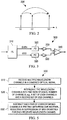
- FIG 1 shows an example of a WDM, or dense WDM (DWDM), optical communications system 100.
- the system 100 includes reconfigurable optical add-drop multiplexers (ROADMs) 110 connected to each other via optical fiber links 101. Although two ROADMs 110 are shown in Figure 1 , the system 100 can include any number of ROADMs 110 interconnected via fiber links 101.
- the ROADM 110 switches WDM traffic at the wavelength layer.
- the ROADM 110 comprises an optical add-drop multiplexer that performs wavelength selective switching. This allows individual or multiple wavelengths carrying data channels to be added and/or dropped from a transport fiber without the need to convert the signals on all of the WDM channels to electronic signals and back again to optical signals.
- a ROADM 110 can transmit on a fiber link 101 (or links) and receive on another fiber link 101 (or links). Additionally, a channel tracking (CT) detector/module 120 is coupled at ingress and egress of fiber links 101 of the ROADMs 110. The CT detector/module 120 performs channel monitoring based on the low frequency modulation in the received signals. The channel monitoring may include power measurement and wavelength identification of optical signals passing through the fiber links 101.
- CT channel tracking
- the signals received on a fiber link 101 may include multiple wavelength channels.
- the multiple wavelength channels propagating in a fiber link 101 may suffer from the SRS effect, where energy in lower wavelength channels tend to transfer to higher wavelength channels, thus changing the original powers/amplitudes of the wavelength channels (which is referred to as crosstalk) and causing signal distortion in the channels, as seen by on the receiver side.
- Channel monitoring at a CT detector/module 120 e.g., at an output of an optical amplifier on the fiber, is affected by the distortions in low frequency modulated signals due to the SRS crosstalk. This results in lower communications efficiency and performance.
- Figure 2 illustrates a SRS effect in multiple wavelength channel signals.
- SRS Signal Power
- the number of spans the number of channels
- channel distribution the fiber type.
- the SRS crosstalk is approximately proportional to the frequency difference between two channels.
- Low frequency modulation on one channel is also transferred to other channels.
- the detected tone power also includes contributions from other channels.
- the channel ⁇ 1 has low frequency modulation f1. Due to SRS, f1 appears on channel ⁇ 2 and ⁇ 3.
- the SRS crosstalk caused error can be more than 5 dB in multi-span systems, making power monitoring useless. The error can be so large that even the channel detection is in error.
- the CT detector/module 120 is configured to suppress the SRS in the received signals. This is achieved by splitting the received multiple channel signals into two non-overlapping sets of equal number of channels, and then subtracting channel pairs in the two sets from one another.
- Figure 3 illustrates an embodiment of a system/apparatus 300 for SRS crosstalk suppression, which can be used when detecting low frequency modulation signals for channel monitoring.
- the apparatus 300 includes an optical interleaver 310, two photo-detectors 320 (e. g., two photodiodes), two amplifier 330 (e.g., amp circuits), and a subtraction circuit 340 (e.g., an op-amp circuit).
- the interleaver 310 is an optical device made using any suitable optical components/designs and configured to separate multiple wavelength channels into two interleaving (non-overlapping) sets of even and odd channels.
- the interleaver 310 comprises a simple one stage Mach-Zehnder (MZ) interferometer.
- the two sets have the same channel separation, which is equal to twice the channel separation in the original incoming combined signal at the input of the interleaver 310.
- the remaining components are electrical/electronic components made using any suitable electronic components/designs, including analog components, digital components, or both.
- Each of the photo- detectors 320 converts a corresponding set of even or odd channels from optical to electrical signals.
- the amplifiers 330 amplify the corresponding electrical signals.
- the subtraction circuit 340 subtracts the corresponding electric signal strengths, which are proportional to the wavelength channel powers, between corresponding pairs of even and odd channels.
- any of the electric signal domain steps can be implemented using digital signal processing (DSP) instead of using circuit components.
- DSP digital signal processing
- the signal subtraction in frequency domain can be implemented using DSP, e.g., via software instead of circuit design.
- DSP digital signal processing
- ADCs analog-to-digital converters
- Figures 4a illustrates power at a plurality of channels.
- the channels include a wavelength channel ⁇ m modulated by low frequency tone f m , channel monitoring purpose.
- Figure 4b shows power redistribution in the fiber from channel ⁇ m to other adjacent channels due to SRS.
- the channel tone may be partially transferred to all other channels through SRS effect. Due to this SRS effect, the channel's power modulated by f m is no longer strictly proportional to the original optical power for ⁇ m , but also contains contributions from other channels.
- the channels are separated using the interleaver 310 into two paths, even channels path and odd channels path.
- One of the two paths contains the channel ⁇ m to be measured with added SRS crosstalk from the even channels.
- the other path contains the SRS crosstalk from the odd channels only.
- the SRS for ⁇ m is suppressed when the SRS crosstalk of the odd channels is subtracted from that of the even channels.
- channel ⁇ m is modulated by frequency f m .
- some of the power of the ⁇ m channel is transferred to the adjacent channels, which is manifested as undesirable crosstalk (power redistribution) between the channels.
- Modulation f m appears in channel ⁇ m , as well as in other channels due to SRS effect.
- the SRS is, to some extent, proportional to the wavelength difference. Thus, the further away an adjacent channel is from channel ⁇ m , the stronger the SRS crosstalk.
- the apparatus 300 may not suppress the SRS crosstalk.
- the suppression is the largest when the channels are split evenly between even and odd channels. Usually the larger the number of channels, the higher the SRS suppression. Better suppression can be achieved by arranging the channels so that they are more evenly split between even and odd channels or any two non-overlapping sets of channels.
- a wavelength selective switch is used in the apparatus 300 instead of the interleaver 310.
- the remaining components of the apparatus 300 may not be changed.
- the WSS is based on multiple optical filters that allow splitting any group of incoming channels into a first set and a second satisfying two criteria, an equal number of channels in each set; and evenly distributed SRS crosstalk for all channels.
- the spacing between the channels in either set does not need to be fixed.
- the WSS allows selecting any arbitrary channels from the group of incoming channels into the two sets to meet these two criteria.
- the two criteria are needed to efficiently suppress the SRS crosstalk by subtracting the detected channel powers between the two sets.
- FIG. 5 illustrates an embodiment of a method 500 for SRS crosstalk suppression.
- the method 500 is implemented at a receiver, for example, a ROADM 110 or CT detector/module 120, which comprises the apparatus 300 or a comparable apparatus/system as described above.
- the method 500 suppresses the SRS crosstalk by subtracting detected signals between two sets of even and odd channels (e.g., using the apparatus 300) or between any two groups of channels that satisfy the two criteria above (e.g., using a WSS and subtraction).
- multiple wavelength channels are received in a combined optical signal.
- the wavelength channels are interleaved into two sets of equal number of channels, e.g., a set of even channels and a second set of odd channels.
- This step is implemented in the optical signal domain, e.g., using an interleaver, a WSS, or any other suitable device.
- each pair of corresponding channels in the two sets is subtracted from one another, resulting in suppression of SRS crosstalk for each received wavelength channel.
- This step is implemented in the electrical signal domain, using detectors and amplifiers that convert and amplify the channel signals from optical to electric domain, and using an electric circuit for subtracting the signals.
- FIG. 6 is a block diagram of an exemplary processing system 600 that can be used to implement various embodiments.
- the processing system 600 can be used to implement some steps of the methods above using DSP and software.
- Specific devices may utilize all of the components shown, or only a subset of the components and levels of integration may vary from device to device.
- a device may contain multiple instances of a component, such as multiple processing units, processors, memories, transmitters, receivers, etc.
- the processing system 600 may comprise a processing unit 601 equipped with one or more input/output devices, such as a network interfaces, storage interfaces, and the like.
- the processing unit 601 may include a central processing unit (CPU) 610, a memory 620, a mass storage device 630, and an I/O interface 660 connected to a bus.
- the bus may be one or more of any type of several bus architectures including a memory bus or memory controller, a peripheral bus or the like.
- the CPU 610 may comprise any type of electronic data processor.
- the memory 620 may comprise any type of system memory such as static random access memory (SRAM), dynamic random access memory (DRAM), synchronous DRAM (SDRAM), read-only memory (ROM), a combination thereof, or the like.
- the memory 620 may include ROM for use at boot-up, and DRAM for program and data storage for use while executing programs.
- the memory 620 is non-transitory.
- the mass storage device 630 may comprise any type of storage device configured to store data, programs, and other information and to make the data, programs, and other information accessible via the bus.
- the mass storage device 630 may comprise, for example, one or more of a solid state drive, hard disk drive, a magnetic disk drive, an optical disk drive, or the like.
- the processing unit 601 also includes one or more network interfaces 650, which may comprise wired links, such as an Ethernet cable or the like, and/or wireless links to access nodes or one or more networks 680.
- the network interface 650 allows the processing unit 601 to communicate with remote units via the networks 680.
- the network interface 650 may provide wireless communication via one or more transmitters/transmit antennas and one or more receivers/receive antennas.
- the processing unit 601 is coupled to a local-area network or a wide-area network for data processing and communications with remote devices, such as other processing units, the Internet, remote storage facilities, or the like.
Landscapes
- Engineering & Computer Science (AREA)
- Computer Networks & Wireless Communication (AREA)
- Signal Processing (AREA)
- Physics & Mathematics (AREA)
- Electromagnetism (AREA)
- Optical Communication System (AREA)
Claims (6)
- Appareil pour supprimer la diaphonie entre des canaux de longueur d'onde dans un signal optique reçu, l'appareil comprenant :un dispositif d'entrelacement (310) configuré pour diviser un signal optique entrant comprenant une pluralité de canaux de longueur d'onde en un premier ensemble de canaux pairs et un deuxième ensemble de canaux impairs, les canaux de longueur d'onde correspondant à des signaux de modulation basse fréquence par rapport à un débit binaire de données de charge utile dans le signal optique, le premier ensemble de canaux pairs et le deuxième ensemble de canaux impairs comprenant environ le même nombre de canaux de longueur d'onde sans recouvrement et présentant un espacement de longueur d'onde régulier, de sorte qu'une diaphonie de diffusion Raman stimulée, SRS, est distribuée uniformément entre les canaux de longueur d'onde dans le premier ensemble et le deuxième ensemble ;un premier photodétecteur (320) couplé à un premier port du dispositif d'entrelacement (310) et configuré pour convertir les canaux de longueur d'onde dans le premier ensemble en un premier ensemble de signaux électriques proportionnels aux puissances de canal des canaux de longueur d'onde dans le premier ensemble ;un deuxième photodétecteur (320) couplé à un deuxième port du dispositif d'entrelacement (310) et configuré pour convertir les canaux de longueur d'onde dans le deuxième ensemble en un deuxième ensemble de signaux électriques proportionnels aux puissances de canal des canaux de longueur d'onde dans le deuxième ensemble ; etun circuit (340) couplé au premier photodétecteur (320) et au deuxième photodétecteur (320) et configuré pour soustraire des amplitudes de signal entre chaque paire correspondante de signaux électriques dans le premier ensemble de signaux électriques et le deuxième ensemble de signaux électriques.
- Appareil selon la revendication 1, comprenant en outre :un premier amplificateur (330) positionné entre le premier photodétecteur (320) et le circuit (340) et couplé à une entrée positive du circuit (340) ; etun deuxième amplificateur (330) positionné entre le deuxième photodétecteur (320) et le circuit et couplé à une entrée négative du circuit (340).
- Appareil selon l'une quelconque des revendications 1 et 2, dans lequel les canaux de longueur d'onde comprennent une diaphonie de SRS stimulée.
- Procédé (500) d'un composant de réseau optique pour supprimer la diaphonie entre des canaux de longueur d'onde dans des signaux optiques reçus, le procédé (500) comprenant les étapes consistant à :recevoir (510) une pluralité de canaux de longueur d'onde correspondant à des signaux de modulation multiples, les canaux de longueur d'onde correspondant à des signaux de modulation basse fréquence par rapport à un débit binaire de données de charge utile dans le signal optique ;diviser (520) les canaux de longueur d'onde en un premier ensemble et un deuxième ensemble de canaux de longueur d'onde, comprenant l'entrelacement des canaux de longueur d'onde en un premier ensemble de canaux pairs et un deuxième ensemble de canaux impairs, les canaux impairs et les canaux pairs présentant un espacement de longueurs d'onde régulier, et le premier ensemble et le deuxième ensemble comprenant environ le même nombre de canaux de longueur d'onde sans recouvrement, de sorte que la diaphonie est distribuée uniformément entre les canaux de longueur d'onde dans le premier ensemble et le deuxième ensemble ;convertir les canaux de longueur d'onde dans le premier ensemble et le deuxième ensemble en signaux électriques proportionnels aux puissances de canal de longueur d'onde des premier et deuxième ensembles respectivement ; etsoustraire (530) des amplitudes de signal entre chaque paire correspondante de signaux électriques dans le premier ensemble et le deuxième ensemble de sorte qu'une diaphonie de diffusion Raman stimulée, SRS, dans les amplitudes de signal correspondant aux canaux de longueur d'onde est réduite.
- Procédé (500) selon la revendication 4, effectué par un récepteur optique configuré pour supprimer la diaphonie SRS stimulée entre la pluralité de canaux de longueur d'onde reçus et le signal optique reçu.
- Procédé (500) selon la revendication 5, dans lequel la soustraction (510) de chaque premier canal de longueur d'onde dans le premier ensemble d'un deuxième canal de longueur d'onde correspondant dans le deuxième ensemble comprend les étapes consistant à :détecter des amplitudes de signal électrique des canaux de longueur d'onde ; etsoustraire les amplitudes de signal électrique entre chaque premier canal de longueur d'onde dans le premier ensemble et le deuxième canal de longueur d'onde correspondant dans le deuxième ensemble.
Applications Claiming Priority (2)
| Application Number | Priority Date | Filing Date | Title |
|---|---|---|---|
| US14/142,392 US9363583B2 (en) | 2013-12-27 | 2013-12-27 | System and method for reducing the stimulated Raman scattering crosstalk in channel monitoring |
| PCT/US2013/078219 WO2015099812A1 (fr) | 2013-12-27 | 2013-12-30 | Système et procédé de réduction de la diaphonie de diffusion raman stimulée, dans des opérations de surveillance de canal |
Publications (3)
| Publication Number | Publication Date |
|---|---|
| EP3078140A1 EP3078140A1 (fr) | 2016-10-12 |
| EP3078140A4 EP3078140A4 (fr) | 2016-12-21 |
| EP3078140B1 true EP3078140B1 (fr) | 2019-03-13 |
Family
ID=53479468
Family Applications (1)
| Application Number | Title | Priority Date | Filing Date |
|---|---|---|---|
| EP13900259.6A Active EP3078140B1 (fr) | 2013-12-27 | 2013-12-30 | Système et procédé de réduction de la diaphonie de diffusion raman stimulée, dans des opérations de surveillance de canal |
Country Status (5)
| Country | Link |
|---|---|
| US (1) | US9363583B2 (fr) |
| EP (1) | EP3078140B1 (fr) |
| CN (1) | CN105900362B (fr) |
| ES (1) | ES2725354T3 (fr) |
| WO (1) | WO2015099812A1 (fr) |
Families Citing this family (5)
| Publication number | Priority date | Publication date | Assignee | Title |
|---|---|---|---|---|
| US20170255078A1 (en) * | 2016-03-03 | 2017-09-07 | Huawei Technologies Co., Ltd. | Wavelength selective switch with monitoring ports |
| US10523315B2 (en) | 2017-04-05 | 2019-12-31 | Huawei Technologies Co., Ltd. | Systems and method of multi-band pilot tone based optical performance monitoring |
| CN110198498B (zh) * | 2018-02-24 | 2021-11-30 | 中兴通讯股份有限公司 | 一种开关控制方法、装置、设备及存储介质 |
| US11057142B1 (en) * | 2020-07-06 | 2021-07-06 | Huawei Technologies Co., Ltd. | Method and system to estimate SRS induced gain change in optical communication networks |
| US12015448B1 (en) * | 2021-01-13 | 2024-06-18 | Veex Inc. | Fast frequency multiplexed optical network channel identification |
Citations (1)
| Publication number | Priority date | Publication date | Assignee | Title |
|---|---|---|---|---|
| US20050094928A1 (en) * | 2003-11-03 | 2005-05-05 | Willie Ng | Bipolar RF-photonic transversal filter with dynamically reconfigurable passbands |
Family Cites Families (8)
| Publication number | Priority date | Publication date | Assignee | Title |
|---|---|---|---|---|
| US5425115A (en) * | 1994-07-18 | 1995-06-13 | Martin Marietta Corporation | Polarization insensitive optical switch |
| WO2002035665A1 (fr) * | 2000-10-19 | 2002-05-02 | Fujitsu Limited | Emetteur optique, repeteur optique et recepteur optique, et procede de transmission optique |
| US7184672B2 (en) * | 2002-09-25 | 2007-02-27 | Nortel Networks Limited | Analogue maintenance detection |
| US8340519B2 (en) * | 2008-05-19 | 2012-12-25 | The Board Of Trustees Of The Leland Stanford Junior University | Passive optical network comprising an optical burst mode receiver |
| US8078054B2 (en) | 2008-06-30 | 2011-12-13 | Alcatel Lucent | Apparatus and method for improving the tolerance of tone-based optical channel monitoring to stimulated Raman scattering |
| US9285575B2 (en) | 2009-01-26 | 2016-03-15 | President And Fellows Of Harvard College | Systems and methods for selective detection and imaging in coherent Raman microscopy by spectral excitation shaping |
| WO2011041472A1 (fr) | 2009-10-02 | 2011-04-07 | Imra America, Inc. | Traitement de signal optique utilisant des lasers à modes synchronisés |
| CN105916210B (zh) | 2010-07-13 | 2019-07-19 | 联发科技(新加坡)私人有限公司 | 无线资源分配方法、无线通信方法以及无线通信网络 |
-
2013
- 2013-12-27 US US14/142,392 patent/US9363583B2/en active Active
- 2013-12-30 WO PCT/US2013/078219 patent/WO2015099812A1/fr not_active Ceased
- 2013-12-30 CN CN201380081906.4A patent/CN105900362B/zh active Active
- 2013-12-30 ES ES13900259T patent/ES2725354T3/es active Active
- 2013-12-30 EP EP13900259.6A patent/EP3078140B1/fr active Active
Patent Citations (1)
| Publication number | Priority date | Publication date | Assignee | Title |
|---|---|---|---|---|
| US20050094928A1 (en) * | 2003-11-03 | 2005-05-05 | Willie Ng | Bipolar RF-photonic transversal filter with dynamically reconfigurable passbands |
Also Published As
| Publication number | Publication date |
|---|---|
| ES2725354T3 (es) | 2019-09-23 |
| WO2015099812A1 (fr) | 2015-07-02 |
| CN105900362B (zh) | 2018-12-07 |
| EP3078140A4 (fr) | 2016-12-21 |
| US20150189407A1 (en) | 2015-07-02 |
| CN105900362A (zh) | 2016-08-24 |
| EP3078140A1 (fr) | 2016-10-12 |
| US9363583B2 (en) | 2016-06-07 |
Similar Documents
| Publication | Publication Date | Title |
|---|---|---|
| US10070206B2 (en) | Reduction of wavelength selective switch (WSS) filter-based impairment using differentiated channel modulation formats | |
| JP6476874B2 (ja) | 光伝送システム、波長制御方法、及び、ノード | |
| EP3097651B1 (fr) | Système et procédé pour un récepteur cohérent de longueurs d'ondes multiples | |
| CN114124287B (zh) | 光信号控制方法及装置、光传输节点和光传输系统 | |
| JP5551825B2 (ja) | 光受信機の電力最適化 | |
| US9363583B2 (en) | System and method for reducing the stimulated Raman scattering crosstalk in channel monitoring | |
| US9660752B2 (en) | Wavelength selective switch (WSS) based multiplexing architecture | |
| EP3590210A1 (fr) | Systèmes et procédé de surveillance de performance optique basée sur une tonalité pilote multi-bande | |
| US9735913B2 (en) | Reduction of wavelength selective switch (WSS) filter-based impairment using selective subcarrier adjustment | |
| US9661407B2 (en) | Reduction of wavelength selective switch (WSS) filter-based impairment using multi-channel forward error correction averaging via interleaving | |
| US20150043920A1 (en) | Submarine reconfigurable optical add/drop multiplexer with passive branching unit | |
| EP2989737A1 (fr) | Architectures de réseau d'accès optique reconfigurables | |
| JP2012070234A (ja) | コヒーレント光受信装置およびコヒーレント光受信方法 | |
| JP2014511058A (ja) | フィルタレスコヒーレント受信装置のデジタル信号対信号ビート雑音低減 | |
| US9929826B2 (en) | Reduction of wavelength selective switch (WSS) filter-based impairment using differentiated channel baud rates | |
| US8879908B2 (en) | Optical channel monitor | |
| JP2020031304A (ja) | クロストーク推定システム | |
| US20160191193A1 (en) | Reduction of wavelength selective switch (wss) filter-based impairment using comparative channel pre-emphasis | |
| CN117397181A (zh) | 用于对模式mux和demux进行反馈控制的方法和装置 | |
| Sakaguchi et al. | SDM-WDM hybrid reconfigurable add-drop nodes for self-homodyne photonic networks | |
| JP2011249943A (ja) | 波長分割多重伝送システム、光チャネルモニタ、光チャネルモニタ方法、及び波長分割多重伝送方法 | |
| EP2445129A1 (fr) | Multiplexeur optique d'insertion/extraction | |
| JP6499516B2 (ja) | 光送受信システム | |
| Corcoran et al. | A wavelength selective switch for optical add/drop multiplexing of sub-bands within Nyquist WDM super-channels | |
| US12574292B2 (en) | Autonomous topology realization for tilt control in an optical segment |
Legal Events
| Date | Code | Title | Description |
|---|---|---|---|
| PUAI | Public reference made under article 153(3) epc to a published international application that has entered the european phase |
Free format text: ORIGINAL CODE: 0009012 |
|
| 17P | Request for examination filed |
Effective date: 20160707 |
|
| AK | Designated contracting states |
Kind code of ref document: A1 Designated state(s): AL AT BE BG CH CY CZ DE DK EE ES FI FR GB GR HR HU IE IS IT LI LT LU LV MC MK MT NL NO PL PT RO RS SE SI SK SM TR |
|
| AX | Request for extension of the european patent |
Extension state: BA ME |
|
| A4 | Supplementary search report drawn up and despatched |
Effective date: 20161117 |
|
| RIC1 | Information provided on ipc code assigned before grant |
Ipc: H04J 14/02 20060101AFI20161111BHEP Ipc: H04B 10/2537 20130101ALI20161111BHEP |
|
| RAP1 | Party data changed (applicant data changed or rights of an application transferred) |
Owner name: HUAWEI TECHNOLOGIES CO., LTD. |
|
| DAX | Request for extension of the european patent (deleted) | ||
| STAA | Information on the status of an ep patent application or granted ep patent |
Free format text: STATUS: EXAMINATION IS IN PROGRESS |
|
| 17Q | First examination report despatched |
Effective date: 20170920 |
|
| GRAP | Despatch of communication of intention to grant a patent |
Free format text: ORIGINAL CODE: EPIDOSNIGR1 |
|
| STAA | Information on the status of an ep patent application or granted ep patent |
Free format text: STATUS: GRANT OF PATENT IS INTENDED |
|
| INTG | Intention to grant announced |
Effective date: 20180927 |
|
| GRAS | Grant fee paid |
Free format text: ORIGINAL CODE: EPIDOSNIGR3 |
|
| GRAA | (expected) grant |
Free format text: ORIGINAL CODE: 0009210 |
|
| STAA | Information on the status of an ep patent application or granted ep patent |
Free format text: STATUS: THE PATENT HAS BEEN GRANTED |
|
| AK | Designated contracting states |
Kind code of ref document: B1 Designated state(s): AL AT BE BG CH CY CZ DE DK EE ES FI FR GB GR HR HU IE IS IT LI LT LU LV MC MK MT NL NO PL PT RO RS SE SI SK SM TR |
|
| REG | Reference to a national code |
Ref country code: GB Ref legal event code: FG4D |
|
| REG | Reference to a national code |
Ref country code: CH Ref legal event code: EP Ref country code: AT Ref legal event code: REF Ref document number: 1109133 Country of ref document: AT Kind code of ref document: T Effective date: 20190315 |
|
| REG | Reference to a national code |
Ref country code: IE Ref legal event code: FG4D |
|
| REG | Reference to a national code |
Ref country code: DE Ref legal event code: R096 Ref document number: 602013052505 Country of ref document: DE |
|
| REG | Reference to a national code |
Ref country code: NL Ref legal event code: MP Effective date: 20190313 |
|
| REG | Reference to a national code |
Ref country code: LT Ref legal event code: MG4D |
|
| PG25 | Lapsed in a contracting state [announced via postgrant information from national office to epo] |
Ref country code: NO Free format text: LAPSE BECAUSE OF FAILURE TO SUBMIT A TRANSLATION OF THE DESCRIPTION OR TO PAY THE FEE WITHIN THE PRESCRIBED TIME-LIMIT Effective date: 20190613 Ref country code: FI Free format text: LAPSE BECAUSE OF FAILURE TO SUBMIT A TRANSLATION OF THE DESCRIPTION OR TO PAY THE FEE WITHIN THE PRESCRIBED TIME-LIMIT Effective date: 20190313 Ref country code: SE Free format text: LAPSE BECAUSE OF FAILURE TO SUBMIT A TRANSLATION OF THE DESCRIPTION OR TO PAY THE FEE WITHIN THE PRESCRIBED TIME-LIMIT Effective date: 20190313 Ref country code: LT Free format text: LAPSE BECAUSE OF FAILURE TO SUBMIT A TRANSLATION OF THE DESCRIPTION OR TO PAY THE FEE WITHIN THE PRESCRIBED TIME-LIMIT Effective date: 20190313 |
|
| PG25 | Lapsed in a contracting state [announced via postgrant information from national office to epo] |
Ref country code: NL Free format text: LAPSE BECAUSE OF FAILURE TO SUBMIT A TRANSLATION OF THE DESCRIPTION OR TO PAY THE FEE WITHIN THE PRESCRIBED TIME-LIMIT Effective date: 20190313 Ref country code: LV Free format text: LAPSE BECAUSE OF FAILURE TO SUBMIT A TRANSLATION OF THE DESCRIPTION OR TO PAY THE FEE WITHIN THE PRESCRIBED TIME-LIMIT Effective date: 20190313 Ref country code: RS Free format text: LAPSE BECAUSE OF FAILURE TO SUBMIT A TRANSLATION OF THE DESCRIPTION OR TO PAY THE FEE WITHIN THE PRESCRIBED TIME-LIMIT Effective date: 20190313 Ref country code: GR Free format text: LAPSE BECAUSE OF FAILURE TO SUBMIT A TRANSLATION OF THE DESCRIPTION OR TO PAY THE FEE WITHIN THE PRESCRIBED TIME-LIMIT Effective date: 20190614 Ref country code: HR Free format text: LAPSE BECAUSE OF FAILURE TO SUBMIT A TRANSLATION OF THE DESCRIPTION OR TO PAY THE FEE WITHIN THE PRESCRIBED TIME-LIMIT Effective date: 20190313 Ref country code: BG Free format text: LAPSE BECAUSE OF FAILURE TO SUBMIT A TRANSLATION OF THE DESCRIPTION OR TO PAY THE FEE WITHIN THE PRESCRIBED TIME-LIMIT Effective date: 20190613 |
|
| REG | Reference to a national code |
Ref country code: AT Ref legal event code: MK05 Ref document number: 1109133 Country of ref document: AT Kind code of ref document: T Effective date: 20190313 |
|
| REG | Reference to a national code |
Ref country code: ES Ref legal event code: FG2A Ref document number: 2725354 Country of ref document: ES Kind code of ref document: T3 Effective date: 20190923 |
|
| PG25 | Lapsed in a contracting state [announced via postgrant information from national office to epo] |
Ref country code: EE Free format text: LAPSE BECAUSE OF FAILURE TO SUBMIT A TRANSLATION OF THE DESCRIPTION OR TO PAY THE FEE WITHIN THE PRESCRIBED TIME-LIMIT Effective date: 20190313 Ref country code: CZ Free format text: LAPSE BECAUSE OF FAILURE TO SUBMIT A TRANSLATION OF THE DESCRIPTION OR TO PAY THE FEE WITHIN THE PRESCRIBED TIME-LIMIT Effective date: 20190313 Ref country code: RO Free format text: LAPSE BECAUSE OF FAILURE TO SUBMIT A TRANSLATION OF THE DESCRIPTION OR TO PAY THE FEE WITHIN THE PRESCRIBED TIME-LIMIT Effective date: 20190313 Ref country code: PT Free format text: LAPSE BECAUSE OF FAILURE TO SUBMIT A TRANSLATION OF THE DESCRIPTION OR TO PAY THE FEE WITHIN THE PRESCRIBED TIME-LIMIT Effective date: 20190713 Ref country code: SK Free format text: LAPSE BECAUSE OF FAILURE TO SUBMIT A TRANSLATION OF THE DESCRIPTION OR TO PAY THE FEE WITHIN THE PRESCRIBED TIME-LIMIT Effective date: 20190313 Ref country code: AL Free format text: LAPSE BECAUSE OF FAILURE TO SUBMIT A TRANSLATION OF THE DESCRIPTION OR TO PAY THE FEE WITHIN THE PRESCRIBED TIME-LIMIT Effective date: 20190313 |
|
| PG25 | Lapsed in a contracting state [announced via postgrant information from national office to epo] |
Ref country code: PL Free format text: LAPSE BECAUSE OF FAILURE TO SUBMIT A TRANSLATION OF THE DESCRIPTION OR TO PAY THE FEE WITHIN THE PRESCRIBED TIME-LIMIT Effective date: 20190313 Ref country code: SM Free format text: LAPSE BECAUSE OF FAILURE TO SUBMIT A TRANSLATION OF THE DESCRIPTION OR TO PAY THE FEE WITHIN THE PRESCRIBED TIME-LIMIT Effective date: 20190313 |
|
| REG | Reference to a national code |
Ref country code: DE Ref legal event code: R097 Ref document number: 602013052505 Country of ref document: DE |
|
| PG25 | Lapsed in a contracting state [announced via postgrant information from national office to epo] |
Ref country code: AT Free format text: LAPSE BECAUSE OF FAILURE TO SUBMIT A TRANSLATION OF THE DESCRIPTION OR TO PAY THE FEE WITHIN THE PRESCRIBED TIME-LIMIT Effective date: 20190313 Ref country code: IS Free format text: LAPSE BECAUSE OF FAILURE TO SUBMIT A TRANSLATION OF THE DESCRIPTION OR TO PAY THE FEE WITHIN THE PRESCRIBED TIME-LIMIT Effective date: 20190713 |
|
| PLBE | No opposition filed within time limit |
Free format text: ORIGINAL CODE: 0009261 |
|
| STAA | Information on the status of an ep patent application or granted ep patent |
Free format text: STATUS: NO OPPOSITION FILED WITHIN TIME LIMIT |
|
| PG25 | Lapsed in a contracting state [announced via postgrant information from national office to epo] |
Ref country code: DK Free format text: LAPSE BECAUSE OF FAILURE TO SUBMIT A TRANSLATION OF THE DESCRIPTION OR TO PAY THE FEE WITHIN THE PRESCRIBED TIME-LIMIT Effective date: 20190313 |
|
| 26N | No opposition filed |
Effective date: 20191216 |
|
| PG25 | Lapsed in a contracting state [announced via postgrant information from national office to epo] |
Ref country code: SI Free format text: LAPSE BECAUSE OF FAILURE TO SUBMIT A TRANSLATION OF THE DESCRIPTION OR TO PAY THE FEE WITHIN THE PRESCRIBED TIME-LIMIT Effective date: 20190313 |
|
| PG25 | Lapsed in a contracting state [announced via postgrant information from national office to epo] |
Ref country code: TR Free format text: LAPSE BECAUSE OF FAILURE TO SUBMIT A TRANSLATION OF THE DESCRIPTION OR TO PAY THE FEE WITHIN THE PRESCRIBED TIME-LIMIT Effective date: 20190313 |
|
| REG | Reference to a national code |
Ref country code: CH Ref legal event code: PL |
|
| REG | Reference to a national code |
Ref country code: BE Ref legal event code: MM Effective date: 20191231 |
|
| PG25 | Lapsed in a contracting state [announced via postgrant information from national office to epo] |
Ref country code: MC Free format text: LAPSE BECAUSE OF FAILURE TO SUBMIT A TRANSLATION OF THE DESCRIPTION OR TO PAY THE FEE WITHIN THE PRESCRIBED TIME-LIMIT Effective date: 20190313 |
|
| PG25 | Lapsed in a contracting state [announced via postgrant information from national office to epo] |
Ref country code: FR Free format text: LAPSE BECAUSE OF NON-PAYMENT OF DUE FEES Effective date: 20191231 Ref country code: IE Free format text: LAPSE BECAUSE OF NON-PAYMENT OF DUE FEES Effective date: 20191230 Ref country code: LU Free format text: LAPSE BECAUSE OF NON-PAYMENT OF DUE FEES Effective date: 20191230 |
|
| PG25 | Lapsed in a contracting state [announced via postgrant information from national office to epo] |
Ref country code: CH Free format text: LAPSE BECAUSE OF NON-PAYMENT OF DUE FEES Effective date: 20191231 Ref country code: LI Free format text: LAPSE BECAUSE OF NON-PAYMENT OF DUE FEES Effective date: 20191231 Ref country code: BE Free format text: LAPSE BECAUSE OF NON-PAYMENT OF DUE FEES Effective date: 20191231 |
|
| PG25 | Lapsed in a contracting state [announced via postgrant information from national office to epo] |
Ref country code: CY Free format text: LAPSE BECAUSE OF FAILURE TO SUBMIT A TRANSLATION OF THE DESCRIPTION OR TO PAY THE FEE WITHIN THE PRESCRIBED TIME-LIMIT Effective date: 20190313 |
|
| PG25 | Lapsed in a contracting state [announced via postgrant information from national office to epo] |
Ref country code: HU Free format text: LAPSE BECAUSE OF FAILURE TO SUBMIT A TRANSLATION OF THE DESCRIPTION OR TO PAY THE FEE WITHIN THE PRESCRIBED TIME-LIMIT; INVALID AB INITIO Effective date: 20131230 Ref country code: MT Free format text: LAPSE BECAUSE OF FAILURE TO SUBMIT A TRANSLATION OF THE DESCRIPTION OR TO PAY THE FEE WITHIN THE PRESCRIBED TIME-LIMIT Effective date: 20190313 |
|
| PG25 | Lapsed in a contracting state [announced via postgrant information from national office to epo] |
Ref country code: MK Free format text: LAPSE BECAUSE OF FAILURE TO SUBMIT A TRANSLATION OF THE DESCRIPTION OR TO PAY THE FEE WITHIN THE PRESCRIBED TIME-LIMIT Effective date: 20190313 |
|
| PGFP | Annual fee paid to national office [announced via postgrant information from national office to epo] |
Ref country code: DE Payment date: 20251104 Year of fee payment: 13 |
|
| PGFP | Annual fee paid to national office [announced via postgrant information from national office to epo] |
Ref country code: GB Payment date: 20251114 Year of fee payment: 13 |
|
| PGFP | Annual fee paid to national office [announced via postgrant information from national office to epo] |
Ref country code: IT Payment date: 20251121 Year of fee payment: 13 |
|
| PGFP | Annual fee paid to national office [announced via postgrant information from national office to epo] |
Ref country code: ES Payment date: 20260119 Year of fee payment: 13 |