EP3078308A1 - Dispositif d'extraction de café - Google Patents
Dispositif d'extraction de café Download PDFInfo
- Publication number
- EP3078308A1 EP3078308A1 EP14867448.4A EP14867448A EP3078308A1 EP 3078308 A1 EP3078308 A1 EP 3078308A1 EP 14867448 A EP14867448 A EP 14867448A EP 3078308 A1 EP3078308 A1 EP 3078308A1
- Authority
- EP
- European Patent Office
- Prior art keywords
- coffee
- discharge
- coffee extracting
- extracting unit
- ambient air
- Prior art date
- Legal status (The legal status is an assumption and is not a legal conclusion. Google has not performed a legal analysis and makes no representation as to the accuracy of the status listed.)
- Granted
Links
Images





Classifications
-
- A—HUMAN NECESSITIES
- A47—FURNITURE; DOMESTIC ARTICLES OR APPLIANCES; COFFEE MILLS; SPICE MILLS; SUCTION CLEANERS IN GENERAL
- A47J—KITCHEN EQUIPMENT; COFFEE MILLS; SPICE MILLS; APPARATUS FOR MAKING BEVERAGES
- A47J31/00—Apparatus for making beverages
- A47J31/24—Coffee-making apparatus in which hot water is passed through the filter under pressure, i.e. in which the coffee grounds are extracted under pressure
- A47J31/34—Coffee-making apparatus in which hot water is passed through the filter under pressure, i.e. in which the coffee grounds are extracted under pressure with hot water under liquid pressure
- A47J31/36—Coffee-making apparatus in which hot water is passed through the filter under pressure, i.e. in which the coffee grounds are extracted under pressure with hot water under liquid pressure with mechanical pressure-producing means
-
- A—HUMAN NECESSITIES
- A47—FURNITURE; DOMESTIC ARTICLES OR APPLIANCES; COFFEE MILLS; SPICE MILLS; SUCTION CLEANERS IN GENERAL
- A47J—KITCHEN EQUIPMENT; COFFEE MILLS; SPICE MILLS; APPARATUS FOR MAKING BEVERAGES
- A47J31/00—Apparatus for making beverages
- A47J31/24—Coffee-making apparatus in which hot water is passed through the filter under pressure, i.e. in which the coffee grounds are extracted under pressure
- A47J31/34—Coffee-making apparatus in which hot water is passed through the filter under pressure, i.e. in which the coffee grounds are extracted under pressure with hot water under liquid pressure
- A47J31/36—Coffee-making apparatus in which hot water is passed through the filter under pressure, i.e. in which the coffee grounds are extracted under pressure with hot water under liquid pressure with mechanical pressure-producing means
- A47J31/3604—Coffee-making apparatus in which hot water is passed through the filter under pressure, i.e. in which the coffee grounds are extracted under pressure with hot water under liquid pressure with mechanical pressure-producing means with a mechanism arranged to move the brewing chamber between loading, infusing and ejecting stations
- A47J31/3623—Cartridges being employed
- A47J31/3628—Perforating means therefor
-
- A—HUMAN NECESSITIES
- A47—FURNITURE; DOMESTIC ARTICLES OR APPLIANCES; COFFEE MILLS; SPICE MILLS; SUCTION CLEANERS IN GENERAL
- A47J—KITCHEN EQUIPMENT; COFFEE MILLS; SPICE MILLS; APPARATUS FOR MAKING BEVERAGES
- A47J31/00—Apparatus for making beverages
- A47J31/44—Parts or details or accessories of beverage-making apparatus
- A47J31/46—Dispensing spouts, pumps, drain valves or like liquid transporting devices
- A47J31/461—Valves, e.g. drain valves
-
- A—HUMAN NECESSITIES
- A47—FURNITURE; DOMESTIC ARTICLES OR APPLIANCES; COFFEE MILLS; SPICE MILLS; SUCTION CLEANERS IN GENERAL
- A47J—KITCHEN EQUIPMENT; COFFEE MILLS; SPICE MILLS; APPARATUS FOR MAKING BEVERAGES
- A47J31/00—Apparatus for making beverages
- A47J31/44—Parts or details or accessories of beverage-making apparatus
- A47J31/46—Dispensing spouts, pumps, drain valves or like liquid transporting devices
- A47J31/469—Details of hydraulic circuits
Definitions
- the present disclosure relates to a coffee extracting device for extracting and supplying coffee to users, and more particularly, to a coffee extracting device capable of preventing coffee from being externally discharged after coffee extraction.
- a coffee extracting device is a device extracting coffee and supplying the same to a user.
- the coffee extracting device includes a coffee extracting unit extracting coffee by grinding coffee beans or extracting coffee using a coffee capsule.
- the coffee extracting device includes a pump and a heater heating water pressurized in the coffee extracting unit and supplying the same to extract coffee.
- coffee may remain in the coffee extracting unit, a discharge line connecting the coffee extracting unit and a discharge member discharging coffee, or the discharge member, and the like.
- the present disclosure is based upon recognition of the requirements and issues arising from the above-referenced related coffee extracting device.
- An aspect of the present disclosure is to prevent coffee from being externally discharged after coffee is extracted.
- Another aspect of the present disclosure is to prevent coffee from remaining after coffee is extracted.
- a coffee extracting device including: a pump connected to a water supply source and pressurizing water supplied from the water supply source; a heater heating water pressurized by the pump; a coffee extracting unit extracting coffee using water heated by the heater; and a discharge member externally discharging coffee which has been extracted by the coffee extracting unit, wherein a vent valve is provided between the heater and the coffee extracting unit, the vent valve being closed during coffee extraction and being opened after coffee extraction.
- an ambient air intake pipe may be connected to the coffee extracting unit to allow ambient air to be introduced to the coffee extracting unit after coffee extraction.
- the coffee extracting unit may extract coffee using a coffee capsule
- the ambient air intake pipe may be connected to an upper portion of a capsule insertion part formed at the coffee extracting unit to allow the coffee capsule to be inserted therein.
- one end of the ambient air intake pipe may communicate with an interior of the coffee extracting unit and the other end of the ambient air intake pipe may communicate with ambient air.
- the other end of the ambient air intake pipe may be positioned to be higher than the one end of the ambient air intake pipe.
- the ambient air intake pipe may have a bent shape.
- the coffee extracting unit and the discharge member may be connected by a discharge line, and an inner diameter of the ambient air intake pipe may be smaller than an inner diameter of the discharge line.
- the coffee extracting unit and the discharge member may be connected by a discharge line, and an ambient air intake pipe may be connected to the discharge line in order to allow ambient air to be introduced to the discharge line after coffee extraction.
- the coffee extracting unit may include a holder having an installation space allowing a coffee capsule to be installed therein and a unit body accommodating the holder, and through holes may be separately formed at mutually corresponding positions of the holder and the unit body to penetrate through an interior and an exterior of the coffee extracting unit.
- an ambient air intake pipe allowing ambient air to be introduced to the interior of the holder may be connected to the through holes.
- the coffee extracting unit and the discharge member may be connected by a discharge line, and a pressing pump may be connected to the discharge line in order to externally discharge coffee remaining in the discharge line through the discharge member after coffee extraction.
- the coffee extracting unit and the discharge member may be connected by a discharge line, and an intake pump may be connected to the discharge line in order to externally discharge coffee remaining in the discharge line after coffee extraction.
- a coffee extracting device including: a pump connected to a water supply source and pressurizing water supplied from the water supply source; a heater heating water pressurized by the pump; a coffee extracting unit extracting coffee using water heated by the heater; and a discharge member externally discharging coffee which has been extracted by the coffee extracting unit, wherein a first vent valve is provided between the heater and the coffee extracting unit, the first vent valve being closed during coffee extraction and being opened after coffee extraction, and a second vent valve is provided between the heater and the discharge member, the second vent valve being closed during coffee extraction and being opened after coffee extraction.
- the heater and the coffee extracting unit may be connected by a connection line, the connection line may be connected to a first vent line, and the first vent valve may be provided in the first vent line.
- the coffee extracting unit and the discharge member may be connected by a discharge line
- the heater and the discharge line may be connected by a second vent line
- the second vent valve may be provided in the second vent line
- water or steam heated by the heater may be externally discharged from the discharge member through the second vent line and the discharge line.
- a communication line allowing an interior and an exterior of the discharge member to communicate with each other may be provided in the discharge member.
- the discharge member may include a discharge pipe receiving extracted coffee from the coffee extracting unit and an intake tube coupled to the discharge pipe and externally discharging coffee, and the intake tube may have a shape in which a top portion and a bottom portion thereof are open.
- the communication line may be provided between the discharge pipe and the intake tube, and after coffee extraction, internal pressure of the intake tube and external pressure of the intake tube may be equal.
- pressure of the coffee extracting unit may be released after coffee extraction.
- residual coffee may not be externally discharged.
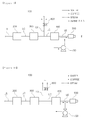
- FIGS. 1 and 2 are schematic views illustrating operations of a coffee extracting device according to an exemplary embodiment in the present disclosure, wherein FIG. 1 illustrates a state when coffee is extracted, and FIG. 2 illustrates a state after coffee is extracted.
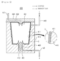
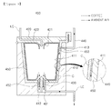
- FIGS. 3 through 5 are schematic views illustrating a coffee extracting unit included in a coffee extracting device and operations thereof according to an exemplary embodiment in the present disclosure, wherein FIG. 3 illustrates a state before coffee is extracted, FIG. 4 illustrates a state when coffee is extracted, and FIG. 5 illustrates a state after coffee is extracted.
- a coffee extracting device 100 may include a pump 200, a heater 300, a coffee extracting unit 400, and a discharge member 500.
- the pump 200 may be connected to a water supply source (not shown). As illustrated in FIG. 1 , the pump 200 may be connected to the water supply source by a supply line LS.
- the water supply source to which the pump 200 is connected may be included in the water treatment device and may be a filtering unit including a water purification filter filtering water or a storage tank connected to the filtering unit and storing filtered water.
- the water supply source to which the pump 200 is connected is not particularly limited, and any known water supply source may be used as long as it can supply water to the pump 200.
- the heater 300 may heat water pressurized by the pump 200. To this end, as illustrated in FIG. 1 , the heater 300 may be connected to the pump 200 by a connection line LC, and water pressurized by the pump 200 may be supplied thereto.
- a configuration of the heater 300 is not particularly limited, and any known component may be used as long as it can heat water.
- the coffee extracting unit 400 may extract coffee using water heated by the heater 300 as illustrated in FIGS. 1 and 4 . To this end, the coffee extracting unit 400 may be connected to the heater 300 by a connection line LC and heated water from the heater 300 may be supplied to the coffee extracting unit 400.
- coffee may be extracted using a coffee capsule C.
- the coffee extracting unit 400 may include a unit body 410 with an open upper portion and a cover 420 hermetically closing the open upper portion of the unit body 410.
- a capsule insertion part 411 into which the coffee capsule C may be inserted, may be formed in the unit body 410.
- a coffee discharge part 412 to which the capsule insertion part 411 and a discharge line LE are connected, may be formed in the unit body 410.
- a small gap may be formed between the coffee capsule C and the capsule insertion part 411 and may serve as a passage along which ambient air introduced through an ambient air intake pipe 440 as described hereinafter moves.
- a piercing member 430 may be provided in the coffee discharge part 412.
- a coffee flow channel 431 may be penetratingly formed in the piercing member 430.
- a lower surface of the coffee capsule C may be pierced by the piercing member 430. Coffee extracted from the coffee capsule C may then move to the coffee discharge part 412 through the coffee flow channel 431 of the piercing member 430.
- a piercing part 421 may be formed on the cover 420. Also, a water supply flow channel 422 connected to the connection line LC may be formed in the cover 420 and the piercing part 421. The cover 420 may be connected to the unit body 410 in a pivoted manner.
- the capsule insertion part 411 may be hermetically closed by closing the open upper portion of the unit body 410 by rotating the cover 420. Also, as illustrated in FIG. 4 , an upper surface of the coffee capsule C may be pierced by the piercing part 421 of the cover 420.
- water heated by the heater 300 is supplied to the water supply flow channel 422 through the connection line LC connected to the heater 300, the heated water may be supplied to the coffee capsule C, and coffee may be extracted. Also, coffee extracted from the coffee capsule C may move to the coffee discharge part 412 through the coffee flow channel 431 of the piercing member 430 and subsequently move to the discharge line LE connected to the coffee discharge part 412.
- a configuration of the coffee extracting unit 400 is not particularly limited, and any known configuration such as extracting coffee by grinding coffee beans may also be adopted.
- the discharge member 500 may discharge coffee extracted from the coffee extracting unit 400 externally.
- the discharge member 500 may be connected to the coffee extracting unit 400 by a discharge line LE. Accordingly, as illustrated in FIG. 4 , coffee extracted from the coffee extracting unit 400 may move along the discharge line LE and be externally discharged through the discharge member 500. The coffee may then be supplied to a user.
- a vent valve 600 may be provided between the heater 300 and the coffee extracting unit 400.
- a vent line LV may be connected to the connection line LC connecting the heater 300 and the coffee extracting unit 400, and a vent valve 600 may be provided in the vent line LV.
- the vent valve 600 is closed when coffee is extracted as illustrated in FIG. 1 , and opened after coffee is extracted as illustrated in FIG. 2 . Accordingly, after coffee extraction, heated water or steam present in the connection line LC connecting the heater 300 and the coffee extracting unit 400 may be externally discharged through the vent valve 600. Also, pressure of the coffee extracting unit 400 may be released.
- coffee remaining in the coffee extracting unit 400, in the discharge line LE connecting the coffee extracting unit 400 and the discharge member 500, or in the discharge member 500 may not be externally discharged.
- an ambient air intake pipe 440 may be connected to the coffee extracting unit 400. As illustrated, the ambient air intake pipe 440 may be connected to an upper portion of the capsule insertion part 411 of the coffee extracting unit 400.
- One end of the ambient air intake pipe 440 may be connected to an interior of the coffee extracting unit 400, and the other end of the ambient air intake pipe 440 may communicate with ambient air.
- the ambient air intake pipe 440 may be closed when coffee is extracted and opened after coffee is extracted.
- ambient air may be introduced to the capsule insertion part 411 of the coffee extracting unit 400 through the ambient air intake pipe 440.
- coffee remaining in the coffee extracting unit 400, the discharge line LE, or the discharge member 500 may be externally discharged by ambient air introduced through the ambient air intake pipe 440. That is, even residual coffee may also be supplied to the user.
- coffee may not remain in the coffee extracting unit 400, the discharge line LE, or the discharge member 500, and since coffee does not remain, coffee is not externally discharged after coffee extraction.
- the other end of the ambient air intake pipe 440 may be positioned to be higher than one end of the ambient air intake pipe 440, and may have a bent shape. Also, an inner diameter of the ambient air intake pipe 440 may be smaller than an inner diameter of the discharge line LE.
- FIG. 6 is a schematic view illustrating a modified example of a connection position of an ambient air intake pipe provided in a coffee extracting device according to an exemplary embodiment in the present disclosure
- FIG. 7 is a schematic view illustrating a modified example of a coffee extracting unit provided in a coffee extracting device according to an exemplary embodiment in the present disclosure
- FIG. 8 is a schematic view illustrating an operation when coffee is extracted in the modified example of the coffee extracting unit illustrated in FIG. 7 .
- the ambient air intake pipe 440 is connected to the coffee extracting unit 400, but the present disclosure is not limited thereto, and the ambient air intake pipe 440 may be connected to the discharge line LE as illustrated in FIG. 6 .
- coffee remaining in the discharge line LE or discharge member 500 may be externally discharged by ambient air introduced through the ambient air intake pipe 440.
- the coffee extracting unit 400 may further include a holder 450.
- the holder 450 may be inserted into the capsule insertion part 411 through the open upper portion of the unit body 410, an installation space 451 may be formed in the holder 450, and the coffee capsule C may be installed in the installation space 451.
- a guide hole 452 may be provided on a lower surface of the holder 450, and the piercing member 430 may be inserted into the holder 450 through the guide hole 452, and accordingly, the coffee capsule C inserted into the installation space 451 of the holder 450 may be pierced by the piercing member 430.
- through holes 453 and 413 may be separately provided in mutually corresponding positions of the holder 450 and the unit body 410, and thus the through holes 453 and 413 penetrate through an interior and an exterior of the coffee extracting unit 400.
- the ambient air intake pipe 440 allowing ambient air to be introduced to the interior of the holder 450 may be connected to the through holes 453 and 413, and as illustrated in FIG. 7 , after coffee is extracted, ambient air may be introduced to the installation space 451 of the holder 450 through the ambient air intake pipe 440.
- At least a portion of the coffee capsule C may not be tightly attached to the holder 450, and accordingly, a small gap may be formed between the coffee capsule C and the holder 450. Such a gap may serve as a passage along which ambient air may move after coffee extraction.
- coffee remaining in the coffee extracting unit 400, the discharge line LE, or the discharge member 500 may be externally discharged by ambient air introduced through the ambient air intake pipe 440.
- FIG. 9 is a schematic view illustrating an operation of a pressing pump provided in a coffee extracting device according to an exemplary embodiment in the present disclosure
- FIG. 10 is a schematic view illustrating an operation of an intake pump provided in a coffee extracting device according to an exemplary embodiment in the present disclosure.
- the coffee extracting device 100 may further include a pressing pump 700 or an intake pump 700'.
- coffee Even though internal pressure of the coffee extracting unit 400 is released by the vent valve 500 after coffee extraction, coffee may remain in the coffee extracting unit 400, the discharge line LE, or the discharge member 500.
- the residual coffee may be externally discharged by ambient air introduced through the ambient air intake pipe 440 described above with reference to FIGS. 3 through 7 , and here, in order to more effectively discharge residual coffee, the pressing pump 700 or the suction pump 700' may be connected to the discharge line LE.
- the residual coffee may be externally discharged from the discharge member 500 through the discharge line LE by the operation of the pressing pump 700. Also, residual coffee may be externally discharged from a discharge unit (not shown) through the discharge line LE by the operation of the suction pump 700'.
- FIG. 11 is a schematic view illustrating an operation of a first vent valve and a second vent valve of a coffee extracting device according to an exemplary embodiment in the present disclosure.
- a first vent valve 600' may be provided between the heater 300 and the coffee extracting unit 400.
- a first vent line LV1 may be connected to the connection line LC connecting the heater 300 and the coffee extracting unit 400, and the first vent valve 600' may be connected to the first vent line LV1.
- the first vent valve 600' may be closed when coffee is extracted, and may be opened after coffee is extracted. Accordingly, after coffee extraction, heated water or steam present in the connection line LC connecting the heater 300 and the coffee extracting unit 400 may be externally discharged through the first vent valve 600'. Also, pressure of the coffee extracting unit 400 may be released.
- a second vent valve 800 may be provided between the heater 300 and the discharge member 500.
- a second vent line LV2 connecting the connection line LC connecting the heater 300 and the coffee extracting unit 400 and the discharge line LE connecting the coffee extracting unit 400 and the discharge member 500 may be provided, and the second vent valve 800 may be provided in the second vent line LV2.
- the second vent valve 800 may be closed when coffee is extracted, and opened after coffee is extracted.
- water or steam supplied from the heater 300 may not flow to the second vent line LV2, and after coffee extraction, water or steam supplied from the heater 300 may be externally discharged from the discharge member 500 through the second vent line LV2 and the discharge line LE. Accordingly, after coffee extraction, coffee remaining in the discharge line LE or the discharge member 500 may be externally discharged.
- FIG. 12 is a perspective view of a discharge member provided in a coffee extracting device according to an exemplary embodiment in the present disclosure
- FIG. 13 is a cross-sectional view of a discharge member provided in a coffee extracting device according to an exemplary embodiment in the present disclosure.
- the discharge member 500 may include a discharge pipe 510 receiving extracted coffee from the coffee extracting unit 400 and an intake tube 520 coupled to the discharge pipe 510 and externally discharging coffee.
- the intake tube 520 may have a shape in which a top portion and a bottom portion thereof are open, and the discharge pipe 510 may be coupled to the intake tube 520 through the open upper portion of the intake tube 520.
- a protrusion 521 protruding toward the discharge pipe 510 may be provided on an inner surface of the intake tube 520, and the discharge pipe 510 may be tightly coupled to the protrusion 521 so as to be coupled to the intake tube 520.
- various schemes such as a press-fit scheme and a screw-fastening scheme may be applied.
- the upper portion of the intake tube 520 may remain open, and accordingly, an interior and an exterior of the intake tube 520 may communicate with each other.
- a communication line LP may be provided in the discharge member 500 to allow an interior and an exterior of the discharge member 500 to communicate with each other.
- a space between the protrusions 521 protruding from the inner surface of the intake tube 520 may serve as the communication line LP.
- internal pressure of the intake tube 520 may be equal to external pressure of the intake tube 520, and thus, after coffee extraction, coffee may not remain within the intake tube 520.
- pressure of the coffee extracting unit may be released after coffee extraction, residual coffee may not be externally discharged after coffee extraction, and coffee may not remain after coffee extraction.
Landscapes
- Engineering & Computer Science (AREA)
- Food Science & Technology (AREA)
- Mechanical Engineering (AREA)
- Apparatus For Making Beverages (AREA)
Applications Claiming Priority (3)
| Application Number | Priority Date | Filing Date | Title |
|---|---|---|---|
| KR20130149952 | 2013-12-04 | ||
| KR1020140166753A KR101897569B1 (ko) | 2013-12-04 | 2014-11-26 | 커피추출장치 |
| PCT/KR2014/011638 WO2015084005A1 (fr) | 2013-12-04 | 2014-12-01 | Dispositif d'extraction de café |
Publications (3)
| Publication Number | Publication Date |
|---|---|
| EP3078308A1 true EP3078308A1 (fr) | 2016-10-12 |
| EP3078308A4 EP3078308A4 (fr) | 2016-11-30 |
| EP3078308B1 EP3078308B1 (fr) | 2020-02-26 |
Family
ID=53504462
Family Applications (1)
| Application Number | Title | Priority Date | Filing Date |
|---|---|---|---|
| EP14867448.4A Active EP3078308B1 (fr) | 2013-12-04 | 2014-12-01 | Dispositif d'extraction de café |
Country Status (4)
| Country | Link |
|---|---|
| US (1) | US10398252B2 (fr) |
| EP (1) | EP3078308B1 (fr) |
| KR (1) | KR101897569B1 (fr) |
| CN (1) | CN105764387B (fr) |
Cited By (1)
| Publication number | Priority date | Publication date | Assignee | Title |
|---|---|---|---|---|
| CN117136024A (zh) * | 2021-04-13 | 2023-11-28 | 弗兰卡凯菲马斯池因股份公司 | 用于制备咖啡饮料的装置 |
Families Citing this family (16)
| Publication number | Priority date | Publication date | Assignee | Title |
|---|---|---|---|---|
| CN107400585B (zh) | 2016-05-18 | 2021-07-30 | Lg电子株式会社 | 啤酒酿造装置 |
| US11224306B2 (en) | 2016-05-18 | 2022-01-18 | Lg Electronics Inc. | Beverage-making apparatus |
| CN107400588B (zh) | 2016-05-18 | 2021-08-03 | Lg电子株式会社 | 啤酒酿造装置 |
| KR102118089B1 (ko) * | 2016-05-18 | 2020-06-03 | 엘지전자 주식회사 | 맥주 제조장치 |
| CN107400583B (zh) | 2016-05-18 | 2021-07-13 | Lg电子株式会社 | 啤酒酿造包及具有其的啤酒酿造装置 |
| US11208621B2 (en) | 2016-05-18 | 2021-12-28 | Lg Electronics Inc. | Beverage-making apparatus |
| CN107400586B (zh) | 2016-05-18 | 2021-05-28 | Lg电子株式会社 | 啤酒酿造装置 |
| KR102380876B1 (ko) * | 2017-05-25 | 2022-03-31 | 엘지전자 주식회사 | 음료 제조기 |
| KR102200598B1 (ko) * | 2017-05-25 | 2021-01-11 | 엘지전자 주식회사 | 음료 제조기 |
| KR102187330B1 (ko) * | 2017-05-29 | 2020-12-07 | 엘지전자 주식회사 | 음료 제조기 |
| KR102528396B1 (ko) * | 2017-09-01 | 2023-05-03 | 엘지전자 주식회사 | 음료 제조기 |
| KR102481829B1 (ko) * | 2017-09-12 | 2022-12-28 | 엘지전자 주식회사 | 음료 제조기 |
| KR102431315B1 (ko) * | 2021-03-08 | 2022-08-10 | 주식회사 제로쓰로 | 에스프레소 추출 장치 및 방법 |
| KR102710930B1 (ko) | 2022-03-21 | 2024-09-27 | 강원대학교산학협력단 | 커피향 기반 커피 선택 서비스 방법과 커피향 기반 커피 선택 장치, 및 이를 포함하는 커피향 기반 커피 자동 추출 방법과 커피향 기반 커피 자동 추출 장치 |
| DE102023001938B4 (de) * | 2023-04-01 | 2026-03-19 | Kastriot Merlaku | Heißgetränke-Brüh-Vorrichtung und Kapsel mit einem Inhalt für ein Heißgetränk |
| KR102947747B1 (ko) | 2023-11-30 | 2026-04-02 | 서태영 | 커피 드립퍼 추출 장치 |
Family Cites Families (22)
| Publication number | Priority date | Publication date | Assignee | Title |
|---|---|---|---|---|
| IT207919Z2 (it) | 1986-03-10 | 1988-02-22 | Gaggia Brevetti | Macchina per caffe espresso |
| US5083504A (en) * | 1989-03-27 | 1992-01-28 | Sanyo Electric Co., Ltd. | Drink extraction apparatus |
| ATE130506T1 (de) * | 1991-07-19 | 1995-12-15 | Eugster Arthur Ag | Espressomaschine. |
| EP1074207B1 (fr) | 1999-08-04 | 2005-05-18 | Gruppo Cimbali S.p.A. | Machine à café espresso |
| WO2002087399A1 (fr) | 2001-04-30 | 2002-11-07 | Bunn-O-Matic Corporation | Systeme de pulverisation a debit variable |
| EP1312291A1 (fr) | 2001-11-20 | 2003-05-21 | M. Schaerer AG | Machine à café |
| US20050188854A1 (en) * | 2002-02-07 | 2005-09-01 | The Coca-Cola Co. | Coffee and tea dispenser |
| JP2005261835A (ja) * | 2004-03-22 | 2005-09-29 | Fuji Electric Retail Systems Co Ltd | 飲料供給装置 |
| KR100538650B1 (ko) | 2004-04-30 | 2005-12-28 | 윤성훈 | 커피메이커를 겸할 수 있는 정수기 |
| US7677158B2 (en) * | 2004-11-03 | 2010-03-16 | Sunbeam Products, Inc. | Beverage maker having brewing chamber adapted to receive coffee pods or loose coffee |
| US7279375B2 (en) * | 2005-06-30 | 2007-10-09 | Intel Corporation | Block contact architectures for nanoscale channel transistors |
| DE202005011204U1 (de) * | 2005-07-16 | 2005-09-22 | Eugster/Frismag Ag | Espressomaschine mit einer Espressobrüheinheit |
| US7640845B2 (en) | 2005-09-12 | 2010-01-05 | Keurig, Incorporated | Drain for beverage forming machine |
| US9486107B2 (en) * | 2006-09-14 | 2016-11-08 | Bunn-O-Matic Corporation | Brewer with air evacuation |
| DE202007008813U1 (de) * | 2007-06-21 | 2007-11-29 | Mahlich, Gotthard | Getränkezubereitungsgerät |
| EP2098143A1 (fr) | 2008-03-06 | 2009-09-09 | Koninklijke Philips Electronics N.V. | Ensemble d'articles appropriés pour l'utilisation dans un processus de fabrication de boisson |
| US8151694B2 (en) * | 2008-08-01 | 2012-04-10 | Keurig, Incorporated | Beverage forming apparatus with centrifugal pump |
| US20100212509A1 (en) * | 2009-02-20 | 2010-08-26 | Pao-Wu Tien | Safety and guide type brewing kettle |
| US9420911B2 (en) * | 2011-02-26 | 2016-08-23 | Alpha Dominchel Ltd | Hot beverage brewing system |
| KR20120114741A (ko) * | 2011-04-08 | 2012-10-17 | 주식회사 다인 | 음료 추출장치 및 방법 |
| DE102011054601A1 (de) * | 2011-10-19 | 2013-04-25 | Eugster/Frismag Ag Elektrohaushaltgeräte | Kaffeemaschine, insbesondere Kaffeevollautomat sowie Verfahren zum Betreiben einer Kaffeemaschine |
| US20130220137A1 (en) * | 2012-02-23 | 2013-08-29 | Alpha Dominche Ltd. | Hot beverage brewing system and use thereof |
-
2014
- 2014-11-26 KR KR1020140166753A patent/KR101897569B1/ko active Active
- 2014-12-01 EP EP14867448.4A patent/EP3078308B1/fr active Active
- 2014-12-01 US US15/038,271 patent/US10398252B2/en active Active
- 2014-12-01 CN CN201480064158.3A patent/CN105764387B/zh active Active
Cited By (1)
| Publication number | Priority date | Publication date | Assignee | Title |
|---|---|---|---|---|
| CN117136024A (zh) * | 2021-04-13 | 2023-11-28 | 弗兰卡凯菲马斯池因股份公司 | 用于制备咖啡饮料的装置 |
Also Published As
| Publication number | Publication date |
|---|---|
| KR101897569B1 (ko) | 2018-09-13 |
| US20160296059A1 (en) | 2016-10-13 |
| EP3078308A4 (fr) | 2016-11-30 |
| CN105764387B (zh) | 2019-03-19 |
| EP3078308B1 (fr) | 2020-02-26 |
| CN105764387A (zh) | 2016-07-13 |
| KR20150065577A (ko) | 2015-06-15 |
| US10398252B2 (en) | 2019-09-03 |
Similar Documents
| Publication | Publication Date | Title |
|---|---|---|
| US10398252B2 (en) | Coffee extraction device | |
| KR20160020501A (ko) | 휴대용 수동 커피머신 | |
| WO2007112096A3 (fr) | Appareil pour préparer des boissons telles que le café et similaire | |
| WO2005096829A3 (fr) | Systeme d'infusion de boisson | |
| HK1105513A2 (en) | Coffee machine | |
| PL1811880T3 (pl) | System z ekspresem do kawy i kapsułką z porcją | |
| CN100493428C (zh) | 包括冲泡室和减压部件的饮料制作装置 | |
| CN107811508A (zh) | 冲泡机和冲泡机制作饮料的方法 | |
| JP2012515007A (ja) | 飲料を調製するための輸送可能なコンパクトな装置 | |
| JP5855803B2 (ja) | 逆止め弁、注入アセンブリ、および飲料調製マシン | |
| CN109419364A (zh) | 阀体以及具有该阀体的咖啡机 | |
| KR20120000145U (ko) | 캡슐 홀더 및 이를 갖는 캡슐 추출장치 | |
| US7870821B2 (en) | Coffee maker and microwave oven having the same | |
| CN111387817B (zh) | 一种加热装置及其使用方法 | |
| CN204467787U (zh) | 一种自带抽水功能的烧水壶 | |
| CN206333748U (zh) | 冲泡机 | |
| KR102307151B1 (ko) | 음료 추출 장치 | |
| KR101774283B1 (ko) | 전자담배용 카트리지 | |
| CN215533632U (zh) | 一种车载咖啡机 | |
| CN215304760U (zh) | 一种可冲泡的杯子 | |
| KR200266692Y1 (ko) | 커피머신의 커피 추출장치 | |
| CN105559604B (zh) | 一种小型全自动咖啡机 | |
| JP2012515005A (ja) | 飲料を調製するための輸送可能なスタンドアロン装置 | |
| CN220124467U (zh) | 一种咖啡胶囊盒及应用有该胶囊盒的咖啡冲泡装置 | |
| CN217610541U (zh) | 一种摩卡杯承粉器及便携式摩卡杯 |
Legal Events
| Date | Code | Title | Description |
|---|---|---|---|
| PUAI | Public reference made under article 153(3) epc to a published international application that has entered the european phase |
Free format text: ORIGINAL CODE: 0009012 |
|
| 17P | Request for examination filed |
Effective date: 20160603 |
|
| AK | Designated contracting states |
Kind code of ref document: A1 Designated state(s): AL AT BE BG CH CY CZ DE DK EE ES FI FR GB GR HR HU IE IS IT LI LT LU LV MC MK MT NL NO PL PT RO RS SE SI SK SM TR |
|
| AX | Request for extension of the european patent |
Extension state: BA ME |
|
| A4 | Supplementary search report drawn up and despatched |
Effective date: 20161027 |
|
| RIC1 | Information provided on ipc code assigned before grant |
Ipc: A47J 31/44 20060101ALI20161021BHEP Ipc: A47J 31/46 20060101ALI20161021BHEP Ipc: A47J 31/36 20060101ALI20161021BHEP Ipc: A47J 31/24 20060101AFI20161021BHEP |
|
| DAX | Request for extension of the european patent (deleted) | ||
| STAA | Information on the status of an ep patent application or granted ep patent |
Free format text: STATUS: EXAMINATION IS IN PROGRESS |
|
| 17Q | First examination report despatched |
Effective date: 20190222 |
|
| GRAP | Despatch of communication of intention to grant a patent |
Free format text: ORIGINAL CODE: EPIDOSNIGR1 |
|
| STAA | Information on the status of an ep patent application or granted ep patent |
Free format text: STATUS: GRANT OF PATENT IS INTENDED |
|
| INTG | Intention to grant announced |
Effective date: 20191021 |
|
| GRAS | Grant fee paid |
Free format text: ORIGINAL CODE: EPIDOSNIGR3 |
|
| GRAA | (expected) grant |
Free format text: ORIGINAL CODE: 0009210 |
|
| STAA | Information on the status of an ep patent application or granted ep patent |
Free format text: STATUS: THE PATENT HAS BEEN GRANTED |
|
| AK | Designated contracting states |
Kind code of ref document: B1 Designated state(s): AL AT BE BG CH CY CZ DE DK EE ES FI FR GB GR HR HU IE IS IT LI LT LU LV MC MK MT NL NO PL PT RO RS SE SI SK SM TR |
|
| REG | Reference to a national code |
Ref country code: GB Ref legal event code: FG4D |
|
| REG | Reference to a national code |
Ref country code: CH Ref legal event code: EP |
|
| REG | Reference to a national code |
Ref country code: AT Ref legal event code: REF Ref document number: 1236607 Country of ref document: AT Kind code of ref document: T Effective date: 20200315 |
|
| REG | Reference to a national code |
Ref country code: IE Ref legal event code: FG4D |
|
| REG | Reference to a national code |
Ref country code: DE Ref legal event code: R096 Ref document number: 602014061684 Country of ref document: DE |
|
| PG25 | Lapsed in a contracting state [announced via postgrant information from national office to epo] |
Ref country code: RS Free format text: LAPSE BECAUSE OF FAILURE TO SUBMIT A TRANSLATION OF THE DESCRIPTION OR TO PAY THE FEE WITHIN THE PRESCRIBED TIME-LIMIT Effective date: 20200226 Ref country code: FI Free format text: LAPSE BECAUSE OF FAILURE TO SUBMIT A TRANSLATION OF THE DESCRIPTION OR TO PAY THE FEE WITHIN THE PRESCRIBED TIME-LIMIT Effective date: 20200226 Ref country code: NO Free format text: LAPSE BECAUSE OF FAILURE TO SUBMIT A TRANSLATION OF THE DESCRIPTION OR TO PAY THE FEE WITHIN THE PRESCRIBED TIME-LIMIT Effective date: 20200526 |
|
| REG | Reference to a national code |
Ref country code: NL Ref legal event code: MP Effective date: 20200226 |
|
| REG | Reference to a national code |
Ref country code: LT Ref legal event code: MG4D |
|
| PG25 | Lapsed in a contracting state [announced via postgrant information from national office to epo] |
Ref country code: BG Free format text: LAPSE BECAUSE OF FAILURE TO SUBMIT A TRANSLATION OF THE DESCRIPTION OR TO PAY THE FEE WITHIN THE PRESCRIBED TIME-LIMIT Effective date: 20200526 Ref country code: LV Free format text: LAPSE BECAUSE OF FAILURE TO SUBMIT A TRANSLATION OF THE DESCRIPTION OR TO PAY THE FEE WITHIN THE PRESCRIBED TIME-LIMIT Effective date: 20200226 Ref country code: GR Free format text: LAPSE BECAUSE OF FAILURE TO SUBMIT A TRANSLATION OF THE DESCRIPTION OR TO PAY THE FEE WITHIN THE PRESCRIBED TIME-LIMIT Effective date: 20200527 Ref country code: HR Free format text: LAPSE BECAUSE OF FAILURE TO SUBMIT A TRANSLATION OF THE DESCRIPTION OR TO PAY THE FEE WITHIN THE PRESCRIBED TIME-LIMIT Effective date: 20200226 Ref country code: IS Free format text: LAPSE BECAUSE OF FAILURE TO SUBMIT A TRANSLATION OF THE DESCRIPTION OR TO PAY THE FEE WITHIN THE PRESCRIBED TIME-LIMIT Effective date: 20200626 Ref country code: SE Free format text: LAPSE BECAUSE OF FAILURE TO SUBMIT A TRANSLATION OF THE DESCRIPTION OR TO PAY THE FEE WITHIN THE PRESCRIBED TIME-LIMIT Effective date: 20200226 |
|
| PG25 | Lapsed in a contracting state [announced via postgrant information from national office to epo] |
Ref country code: NL Free format text: LAPSE BECAUSE OF FAILURE TO SUBMIT A TRANSLATION OF THE DESCRIPTION OR TO PAY THE FEE WITHIN THE PRESCRIBED TIME-LIMIT Effective date: 20200226 |
|
| PG25 | Lapsed in a contracting state [announced via postgrant information from national office to epo] |
Ref country code: DK Free format text: LAPSE BECAUSE OF FAILURE TO SUBMIT A TRANSLATION OF THE DESCRIPTION OR TO PAY THE FEE WITHIN THE PRESCRIBED TIME-LIMIT Effective date: 20200226 Ref country code: RO Free format text: LAPSE BECAUSE OF FAILURE TO SUBMIT A TRANSLATION OF THE DESCRIPTION OR TO PAY THE FEE WITHIN THE PRESCRIBED TIME-LIMIT Effective date: 20200226 Ref country code: CZ Free format text: LAPSE BECAUSE OF FAILURE TO SUBMIT A TRANSLATION OF THE DESCRIPTION OR TO PAY THE FEE WITHIN THE PRESCRIBED TIME-LIMIT Effective date: 20200226 Ref country code: PT Free format text: LAPSE BECAUSE OF FAILURE TO SUBMIT A TRANSLATION OF THE DESCRIPTION OR TO PAY THE FEE WITHIN THE PRESCRIBED TIME-LIMIT Effective date: 20200719 Ref country code: ES Free format text: LAPSE BECAUSE OF FAILURE TO SUBMIT A TRANSLATION OF THE DESCRIPTION OR TO PAY THE FEE WITHIN THE PRESCRIBED TIME-LIMIT Effective date: 20200226 Ref country code: SK Free format text: LAPSE BECAUSE OF FAILURE TO SUBMIT A TRANSLATION OF THE DESCRIPTION OR TO PAY THE FEE WITHIN THE PRESCRIBED TIME-LIMIT Effective date: 20200226 Ref country code: LT Free format text: LAPSE BECAUSE OF FAILURE TO SUBMIT A TRANSLATION OF THE DESCRIPTION OR TO PAY THE FEE WITHIN THE PRESCRIBED TIME-LIMIT Effective date: 20200226 Ref country code: SM Free format text: LAPSE BECAUSE OF FAILURE TO SUBMIT A TRANSLATION OF THE DESCRIPTION OR TO PAY THE FEE WITHIN THE PRESCRIBED TIME-LIMIT Effective date: 20200226 Ref country code: EE Free format text: LAPSE BECAUSE OF FAILURE TO SUBMIT A TRANSLATION OF THE DESCRIPTION OR TO PAY THE FEE WITHIN THE PRESCRIBED TIME-LIMIT Effective date: 20200226 |
|
| REG | Reference to a national code |
Ref country code: AT Ref legal event code: MK05 Ref document number: 1236607 Country of ref document: AT Kind code of ref document: T Effective date: 20200226 |
|
| REG | Reference to a national code |
Ref country code: DE Ref legal event code: R097 Ref document number: 602014061684 Country of ref document: DE |
|
| PLBE | No opposition filed within time limit |
Free format text: ORIGINAL CODE: 0009261 |
|
| STAA | Information on the status of an ep patent application or granted ep patent |
Free format text: STATUS: NO OPPOSITION FILED WITHIN TIME LIMIT |
|
| PG25 | Lapsed in a contracting state [announced via postgrant information from national office to epo] |
Ref country code: AT Free format text: LAPSE BECAUSE OF FAILURE TO SUBMIT A TRANSLATION OF THE DESCRIPTION OR TO PAY THE FEE WITHIN THE PRESCRIBED TIME-LIMIT Effective date: 20200226 |
|
| 26N | No opposition filed |
Effective date: 20201127 |
|
| PG25 | Lapsed in a contracting state [announced via postgrant information from national office to epo] |
Ref country code: PL Free format text: LAPSE BECAUSE OF FAILURE TO SUBMIT A TRANSLATION OF THE DESCRIPTION OR TO PAY THE FEE WITHIN THE PRESCRIBED TIME-LIMIT Effective date: 20200226 Ref country code: SI Free format text: LAPSE BECAUSE OF FAILURE TO SUBMIT A TRANSLATION OF THE DESCRIPTION OR TO PAY THE FEE WITHIN THE PRESCRIBED TIME-LIMIT Effective date: 20200226 |
|
| REG | Reference to a national code |
Ref country code: CH Ref legal event code: PL |
|
| PG25 | Lapsed in a contracting state [announced via postgrant information from national office to epo] |
Ref country code: MC Free format text: LAPSE BECAUSE OF FAILURE TO SUBMIT A TRANSLATION OF THE DESCRIPTION OR TO PAY THE FEE WITHIN THE PRESCRIBED TIME-LIMIT Effective date: 20200226 |
|
| REG | Reference to a national code |
Ref country code: BE Ref legal event code: MM Effective date: 20201231 |
|
| PG25 | Lapsed in a contracting state [announced via postgrant information from national office to epo] |
Ref country code: IE Free format text: LAPSE BECAUSE OF NON-PAYMENT OF DUE FEES Effective date: 20201201 Ref country code: LU Free format text: LAPSE BECAUSE OF NON-PAYMENT OF DUE FEES Effective date: 20201201 |
|
| PG25 | Lapsed in a contracting state [announced via postgrant information from national office to epo] |
Ref country code: LI Free format text: LAPSE BECAUSE OF NON-PAYMENT OF DUE FEES Effective date: 20201231 Ref country code: CH Free format text: LAPSE BECAUSE OF NON-PAYMENT OF DUE FEES Effective date: 20201231 |
|
| PG25 | Lapsed in a contracting state [announced via postgrant information from national office to epo] |
Ref country code: TR Free format text: LAPSE BECAUSE OF FAILURE TO SUBMIT A TRANSLATION OF THE DESCRIPTION OR TO PAY THE FEE WITHIN THE PRESCRIBED TIME-LIMIT Effective date: 20200226 Ref country code: MT Free format text: LAPSE BECAUSE OF FAILURE TO SUBMIT A TRANSLATION OF THE DESCRIPTION OR TO PAY THE FEE WITHIN THE PRESCRIBED TIME-LIMIT Effective date: 20200226 Ref country code: CY Free format text: LAPSE BECAUSE OF FAILURE TO SUBMIT A TRANSLATION OF THE DESCRIPTION OR TO PAY THE FEE WITHIN THE PRESCRIBED TIME-LIMIT Effective date: 20200226 |
|
| PG25 | Lapsed in a contracting state [announced via postgrant information from national office to epo] |
Ref country code: MK Free format text: LAPSE BECAUSE OF FAILURE TO SUBMIT A TRANSLATION OF THE DESCRIPTION OR TO PAY THE FEE WITHIN THE PRESCRIBED TIME-LIMIT Effective date: 20200226 Ref country code: AL Free format text: LAPSE BECAUSE OF FAILURE TO SUBMIT A TRANSLATION OF THE DESCRIPTION OR TO PAY THE FEE WITHIN THE PRESCRIBED TIME-LIMIT Effective date: 20200226 |
|
| PG25 | Lapsed in a contracting state [announced via postgrant information from national office to epo] |
Ref country code: BE Free format text: LAPSE BECAUSE OF NON-PAYMENT OF DUE FEES Effective date: 20201231 |
|
| PGFP | Annual fee paid to national office [announced via postgrant information from national office to epo] |
Ref country code: IT Payment date: 20250924 Year of fee payment: 12 |
|
| PGFP | Annual fee paid to national office [announced via postgrant information from national office to epo] |
Ref country code: FR Payment date: 20250925 Year of fee payment: 12 |
|
| PGFP | Annual fee paid to national office [announced via postgrant information from national office to epo] |
Ref country code: DE Payment date: 20250922 Year of fee payment: 12 |
|
| PGFP | Annual fee paid to national office [announced via postgrant information from national office to epo] |
Ref country code: GB Payment date: 20251001 Year of fee payment: 12 |