EP3078449A1 - Dispositif de fixation - Google Patents
Dispositif de fixation Download PDFInfo
- Publication number
- EP3078449A1 EP3078449A1 EP14867193.6A EP14867193A EP3078449A1 EP 3078449 A1 EP3078449 A1 EP 3078449A1 EP 14867193 A EP14867193 A EP 14867193A EP 3078449 A1 EP3078449 A1 EP 3078449A1
- Authority
- EP
- European Patent Office
- Prior art keywords
- end side
- locking members
- clamp rod
- hole
- support cylinder
- Prior art date
- Legal status (The legal status is an assumption and is not a legal conclusion. Google has not performed a legal analysis and makes no representation as to the accuracy of the status listed.)
- Granted
Links
Images

Classifications
-
- B—PERFORMING OPERATIONS; TRANSPORTING
- B25—HAND TOOLS; PORTABLE POWER-DRIVEN TOOLS; MANIPULATORS
- B25B—TOOLS OR BENCH DEVICES NOT OTHERWISE PROVIDED FOR, FOR FASTENING, CONNECTING, DISENGAGING, OR HOLDING
- B25B5/00—Clamps
- B25B5/06—Arrangements for positively actuating jaws
- B25B5/061—Arrangements for positively actuating jaws with fluid drive
-
- B—PERFORMING OPERATIONS; TRANSPORTING
- B23—MACHINE TOOLS; METAL-WORKING NOT OTHERWISE PROVIDED FOR
- B23B—TURNING; BORING
- B23B31/00—Chucks; Expansion mandrels; Adaptations thereof for remote control
- B23B31/40—Expansion mandrels
- B23B31/404—Gripping the work or tool by jaws moving radially controlled by conical surfaces
- B23B31/4053—Gripping the work or tool by jaws moving radially controlled by conical surfaces using fluid-pressure means to actuate the gripping means
-
- B—PERFORMING OPERATIONS; TRANSPORTING
- B23—MACHINE TOOLS; METAL-WORKING NOT OTHERWISE PROVIDED FOR
- B23Q—DETAILS, COMPONENTS, OR ACCESSORIES FOR MACHINE TOOLS, e.g. ARRANGEMENTS FOR COPYING OR CONTROLLING; MACHINE TOOLS IN GENERAL CHARACTERISED BY THE CONSTRUCTION OF PARTICULAR DETAILS OR COMPONENTS; COMBINATIONS OR ASSOCIATIONS OF METAL-WORKING MACHINES, NOT DIRECTED TO A PARTICULAR RESULT
- B23Q1/00—Members which are comprised in the general build-up of a form of machine, particularly relatively large fixed members
- B23Q1/0063—Connecting non-slidable parts of machine tools to each other
- B23Q1/0081—Connecting non-slidable parts of machine tools to each other using an expanding clamping member insertable in a receiving hole
-
- B—PERFORMING OPERATIONS; TRANSPORTING
- B23—MACHINE TOOLS; METAL-WORKING NOT OTHERWISE PROVIDED FOR
- B23Q—DETAILS, COMPONENTS, OR ACCESSORIES FOR MACHINE TOOLS, e.g. ARRANGEMENTS FOR COPYING OR CONTROLLING; MACHINE TOOLS IN GENERAL CHARACTERISED BY THE CONSTRUCTION OF PARTICULAR DETAILS OR COMPONENTS; COMBINATIONS OR ASSOCIATIONS OF METAL-WORKING MACHINES, NOT DIRECTED TO A PARTICULAR RESULT
- B23Q3/00—Devices holding, supporting, or positioning work or tools, of a kind normally removable from the machine
- B23Q3/02—Devices holding, supporting, or positioning work or tools, of a kind normally removable from the machine for mounting on a work-table, tool-slide, or analogous part
- B23Q3/06—Work-clamping means
- B23Q3/08—Work-clamping means other than mechanically-actuated
- B23Q3/082—Work-clamping means other than mechanically-actuated hydraulically actuated
-
- B—PERFORMING OPERATIONS; TRANSPORTING
- B25—HAND TOOLS; PORTABLE POWER-DRIVEN TOOLS; MANIPULATORS
- B25B—TOOLS OR BENCH DEVICES NOT OTHERWISE PROVIDED FOR, FOR FASTENING, CONNECTING, DISENGAGING, OR HOLDING
- B25B11/00—Work holders not covered by any preceding group in the subclass, e.g. magnetic work holders, vacuum work holders
-
- B—PERFORMING OPERATIONS; TRANSPORTING
- B25—HAND TOOLS; PORTABLE POWER-DRIVEN TOOLS; MANIPULATORS
- B25B—TOOLS OR BENCH DEVICES NOT OTHERWISE PROVIDED FOR, FOR FASTENING, CONNECTING, DISENGAGING, OR HOLDING
- B25B5/00—Clamps
- B25B5/14—Clamps for work of special profile
-
- B—PERFORMING OPERATIONS; TRANSPORTING
- B25—HAND TOOLS; PORTABLE POWER-DRIVEN TOOLS; MANIPULATORS
- B25B—TOOLS OR BENCH DEVICES NOT OTHERWISE PROVIDED FOR, FOR FASTENING, CONNECTING, DISENGAGING, OR HOLDING
- B25B5/00—Clamps
- B25B5/16—Details, e.g. jaws, jaw attachments
Definitions
- the present invention relates to a clamping apparatus.
- the present invention relates to an apparatus configured to clamp a to-be-clamped object such as a workpiece or a die, with the use of a hole formed in the to-be-clamped object.
- Known clamping apparatuses of this type include an apparatus described in Patent Literature 1 (Japanese Unexamined Patent Publication No. 36314/2010 (Tokukai 2010-36314 )).
- the above known apparatus is structured as follows.
- locking members to be inserted into a hole of a to-be-clamped object are arranged circumferentially into an annular shape.
- Wedge surfaces provided at an upper portion of a clamp rod are respectively engaged, from above, with inclined surfaces provided on inner peripheries of upper half portions of the locking members. Further, inner peripheral surfaces of lower half portions of the locking members are in contact with an outer peripheral surface of a lower portion of the clamp rod.
- the clamp rod is driven downward. Then, the locking members first move radially outward, to come into close contact with an inner peripheral surface of the hole. Subsequently, the to-be-clamped object is lowered through the locking members and the inner peripheral surface of the hole which are in a close contact state, so that the to-be-clamped object is clamped on a seating surface.
- Patent Literature 1 Japanese Unexamined Patent Publication No. 36314/2010 (Tokukai 2010-36314 )
- the known clamping apparatus is configured so that, for clamping a to-be-clamped object having a smaller-diameter hole, the outer diameter size of the clamp rod is reduced, to decrease the outer diameter size of the annular shape of the locking members (grippers) when the locking members in the annular shape are switched to an unclamping position.
- the outer diameter size of the clamp rod is reduced, to decrease the outer diameter size of the annular shape of the locking members (grippers) when the locking members in the annular shape are switched to an unclamping position.
- An object of the present invention is to provide a clamping apparatus capable of clamping a to-be-clamped object having a smaller-diameter hole.
- the present invention structures a clamping apparatus as follows, for example, as shown in FIG. 1 A to FIG. 3B .
- a pair of locking members 22, 22 protruding toward a leading end side relative to a housing 1 and configured to be inserted into a hole of a to-be-clamped object are arranged to be capable of being respectively pressed onto opposed portions of an inner peripheral surface of the hole.
- An advancing means 38 configured to push the locking members 22, 22 with a predetermined force toward the leading end side is provided. Wedge surfaces 33, 33 of the clamp rod 32 are respectively engaged with the locking members 22, 22 from the leading end side.
- the clamp rod 32 is configured to be driven by a driving means D toward a base end side for clamping and toward leading end side for unclamping.
- recesses 50, 50 are formed, in an outer peripheral surface of the clamp rod 32, at a portion of the clamp rod 32 which is located on the base end side relative to the wedge surfaces 33, 33, the recesses 50, 50 being configured to respectively accommodate the locking members 22, 22 in such a manner that inner base portions of the locking members 22, 22 in an unclamping position are allowed to contact each other or to get closer to each other.
- the present invention brings about the following functions and effects.
- the apparatus is configured as follows: the pair of locking members configured to be inserted into the hole of the to-be-clamped object and to be pressed onto the opposed portions of the inner peripheral surface of the hole are provided; the recesses configured to respectively accommodate the inner base portions of the locking members in the unclamping position are formed, in the outer peripheral surface of the clamp rod, at the portion of the clamp rod which is located on the base end side relative to the wedge surfaces; and the inner base portions of the pair of locking members are allowed to contact each other or to get closer to each other.
- the pair of locking members in the unclamping position has a significantly smaller outer diameter size.
- the clamping apparatus capable of clamping a to-be-clamped object having a smaller-diameter hole.
- the recesses 50, 50 are communicatively connected to each other inside the clamp rod 32.
- the clamping apparatus is capable of clamping a to-be-clamped object having a hole with a further smaller diameter.
- an inclination angle of each wedge surface 33 relative to an axis of the clamp rod 32 is set within a range from 10 degrees to 40 degrees, and it is more preferable that the inclination angle is set within a range from 15 degrees to 25 degrees.
- the driving means D includes a piston 7 inserted into the housing 1, and a piston rod 8 protruding from the piston 7 toward the leading end side.
- the advancing means 38 includes a support cylinder 39 and a spring 40 urging the support cylinder 39 toward the leading end side, the support cylinder 39 being inserted into an annular space between the housing 1 and the piston rod 8 and being capable of receiving the locking members 22, 22 from the base end side.
- a connection cylinder 42 connecting the piston rod 8 with the clamp rod 32 is inserted into an annular space between the support cylinder 39 and the piston rod 8, and the connection cylinder 42 and the piston rod 8 are fixed to each other by a connection pin 43 extending radially.
- connection pin 43 Both end portions of the connection pin 43 are respectively inserted into pin holes 47, 47 formed in a peripheral wall of the support cylinder 39.
- a base end wall of each pin hole 47 prevents the piston rod 8 from moving toward the base end side a distance greater than a predetermined distance relative to the support cylinder 39.
- connection pin is received by the lower walls of the pin holes.
- the piston rod is prevented from descending a distance greater than the predetermined distance, relative to the support cylinder. This prevents the pair of locking members from excessively moving radially outward.
- a guide member 16 protruding toward the leading end side relative to the housing 1 is provided, and a peripheral wall 18 of the guide member 16 is configured to be insertable into the hole of the to-be-clamped object.
- the guide member 16 includes a guide groove 21 penetrating the peripheral wall 18, and the guide groove 21 is configured to support the corresponding locking member 22 so that the locking member 22 is movable radially. Further, the support cylinder 39 is configured to receive the locking members 22, 22 via the guide member 16 from the base end side.
- the locking members are smoothly inserted into the hole of the to-be-clamped object via the guide member.
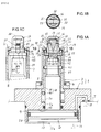
- FIG. 1A to FIG. 3B show an embodiment of the present invention.
- a clamping apparatus of this embodiment is used to clamp a workpiece functioning as a to-be-clamped object.
- FIG. 1A to FIG. 1C and FIG. 2 the structure of the clamping apparatus will be described.
- a housing 1 is mounted on a stationary stand T such as a table.
- the housing 1 includes: a lower housing 2 fixed to the stationary stand T with a plurality of bolts (not illustrated); and a cylindrical upper housing 3 placed on a top surface of the lower housing 2.
- the lower housing 2 and the upper housing 3 are fastened to each other with a plurality of bolts 4.
- the lower housing 2 has a larger-diameter cylinder hole 2a, a smaller-diameter hole 2b, and a medium-diameter hole 2c, which are located from bottom to top in this order.
- a seating surface 5 configured to receive a workpiece (not illustrated) functioning as the to-be-clamped object.
- a piston 7 is hermetically inserted into the cylinder hole 2a.
- a piston rod 8 protruding upward from the piston 7 is hermetically inserted into the smaller-diameter hole 2b.
- Compressed air is supplied to and discharged from a clamp chamber 10 formed above the piston 7 through a supply and discharge port 11. Further, compressed air is supplied to and discharged from an unclamp chamber 12 formed below the piston 7 via a different supply and discharge port 13.
- the piston 7, the piston rod 8, the clamp chamber 10, and the unclamp chamber 12 structure a driving means D for a clamp rod 32, which will be described later.
- a guide member 16 is inserted into an upper portion of the upper housing 3 so as to be movable vertically (axially).
- the guide member 16 includes a top wall 17 and a peripheral wall 18 which are formed integrally and seamlessly.
- the guide member 16 protrudes upward (toward a leading end side) relative to an upper end (leading end) of the upper housing 3, and therefore the guide member 16 is insertable into a hole of the workpiece (these are not illustrated) functioning as the to-be-clamped object.
- a flange portion 19 protrudes radially outward from a lower portion of the peripheral wall 18, and the flange portion 19 is inserted into the upper portion of the upper housing 3 so as to be to be movable radially (horizontally).
- a pair of guide grooves 21, 21 are formed to face each other.
- a locking member 22 is inserted so as to be movable radially (horizontally).
- the locking member 22 includes: an engaging portion 23 configured to be pressed onto an inner peripheral surface of the hole of the workpiece; and a base portion 24 formed below the engaging portion 23. An under surface of the base portion 24 is supported by a top surface of the flange portion 19.
- Each base portion 24 has an attachment groove 25 formed in its outer peripheral surface so as to extend circumferentially.
- An elastic member 29 formed into a thin strip-like shape and made of rubber or synthetic resin is fitted in the attachment grooves 25, 25 and on portions of an outer peripheral surface of the guide member 16. With this, the elastic member 29 urges each locking member 22 radially inward. That is to say, the elastic member 29 structures a returning means for the locking members 22, 22.
- a dust seal 30 is arranged between an upper portion of an inner peripheral surface of the upper housing 3 and the base portions 24.
- the dust seal 30 is made of synthetic resin or the like, and an inner periphery of the dust seal 30 is in contact with an outer peripheral surface of the elastic member 29. With this, the dust seal 30 urges the locking members 22, 22 and the guide member 16 radially inward.
- the clamp rod 32 is insertable into the guide member 16 from below (from a base end side). Further, wedge surfaces 33, 33 provided in an upper portion of the clamp rod 32 are respectively engaged, from above, with inclined surfaces 35, 35 formed on respective inner surfaces of the locking members 22. Each wedge surface 33 and each inclined surface 35 are inclined so that the distance from the axis of the clamp rod 32 decreases toward their lower ends. In this embodiment, each wedge surface 33 and each inclined surface 35 are flat surfaces.
- the inclination angle of each wedge surface 33 relative to the axis of the clamp rod 32 is set within a range from approximately 18 degrees to approximately 22 degrees in this embodiment. It is preferable that the inclination angle is set within a range from 15 degrees to 25 degrees. The inclination angle may be set within a range from 10 degrees to 40 degrees.
- the advancing means 38 includes: a support cylinder 39 which is inserted into an annular space between the housing 1 and the piston rod 8 and is capable of receiving the locking members 22, 22 from below (from the base end side); and a spring 40 urging the support cylinder 39 upward.
- the support cylinder 39 receives the locking members 22, 22 from below via the guide member 16.
- connection cylinder 42 connecting the piston rod 8 with the clamp rod 32 is inserted into an annular space between the support cylinder 39 and the piston rod 8.
- the connection cylinder 42 and the piston rod 8 are fixed to each other by a connection pin 43 extending radially (horizontally).
- a lower flange 45 of the clamp rod 32 is supported between an upper end portion of the connection cylinder 42 and an upper end surface of the piston rod 8 so as to be movable radially (horizontally).
- connection pin 43 both end portions of the connection pin 43 are respectively inserted into pin holes 47, 47 formed through a peripheral wall of the support cylinder 39.
- a lower wall (base end wall) of each pin hole 47 prevents the piston rod 8 from moving downward (toward the base end side) a distance greater than a predetermined distance relative to the support cylinder 39.
- the clamp rod 32 has a through hole 49 formed below the wedge surfaces 33 and extending in a direction substantially orthogonal to the axis of the clamp rod 32.
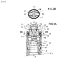
- a pair of recesses 50, 50 are formed in an outer peripheral surface of the clamp rod 32, at both end portions of the through hole 49. That is, in this embodiment, the pair of recesses 50, 50 are communicatively connected to each other.
- each recess 50 accommodates an inner base portion of the corresponding locking member 22 in an unclamping position, and the inner lower portions of the locking members 22, 22 are in contact with each other.
- the inner lower portions of the locking member 22, 22 may be close to each other with a predetermined gap between them.
- the above-described clamping apparatus operates as follows.
- the hole of the workpiece is fitted, with a predetermined gap, to the peripheral wall 18 of the guide member 16 and to the engaging portion 23 of each locking member 22, and an under surface of the workpiece is received by the seating surface 5 of the upper housing 3.
- the clamp rod 32 first descends relative to the guide member 16 and the locking members 22, 22 held at a raised position by the urging force of the spring 40. Then, each wedge surface 33 of the clamp rod 32 pushes the corresponding locking member 22 radially outward, and therefore the engaging portion 23 of each locking member 22 is engaged with the hole of the workpiece (these are not illustrated), for example, by plastically deforming the inner peripheral surface of the hole or by frictionally contacting the inner peripheral surface. Subsequently, in the above engaged state, the clamp rod 32 drives each locking member 22 and the guide member 16 downward for locking, against the urging force of the spring 40. With this, the locking members 22, 22 pull the workpiece downward, with the result that the under surface of the workpiece is firmly clamped on the seating surface 5 of the upper housing 3.
- connection pin 43 is received by the lower walls of the pin holes 47, 47, as shown in an idly clamping state of FIG. 3A and FIG. 3B .
- This structure prevents the piston rod 8 from descending a distance greater than the predetermined distance, relative to the support cylinder 39. This prevents the dust seal 30 from being excessively compressed by each locking member 22.
- each wedge surface 33 is set within the range from 10 degrees to 40 degrees, and each recess 50 is configured to accommodate the inner base portion of the corresponding locking member 22 in the unclamping position.
- the radially movable distance of each locking member 22 is increased. This expands the allowable range with respect to the diameter of the hole of the to-be-clamped object.
- the clamping apparatus of the present invention is adaptable to different workpieces (to-be-clamped objects), i.e., workpieces each having a smaller-diameter hole and workpieces each having a larger-diameter hole. That is, the single clamping apparatus is capable of clamping a workpiece having a smaller-diameter hole and a workpiece having a larger-diameter hole.
- Pressurized fluid used in the driving means D may be liquid such as pressurized oil, instead of compressed air.
- the driving means D may be of a single-acting type such as a spring-releasing type or a spring-locking type, instead of the double-acting type, which has been described as an example. Further, the driving means D may be another type of actuator such as an electric motor, instead of the fluid pressure actuator.
- the pair of recesses 50, 50 are merely required to be formed in the outer peripheral surface of the clamp rod 32.
- the pair of recesses 50, 50 do not have to be communicatively connected to each other.
- the guide member 16 may be omitted to expose the locking member 22 to the outside.
Landscapes
- Engineering & Computer Science (AREA)
- Mechanical Engineering (AREA)
- Jigs For Machine Tools (AREA)
Applications Claiming Priority (2)
| Application Number | Priority Date | Filing Date | Title |
|---|---|---|---|
| JP2013266021A JP6283219B2 (ja) | 2013-12-05 | 2013-12-05 | クランプ装置 |
| PCT/JP2014/081467 WO2015083625A1 (fr) | 2013-12-05 | 2014-11-27 | Dispositif de fixation |
Publications (3)
| Publication Number | Publication Date |
|---|---|
| EP3078449A1 true EP3078449A1 (fr) | 2016-10-12 |
| EP3078449A4 EP3078449A4 (fr) | 2017-08-16 |
| EP3078449B1 EP3078449B1 (fr) | 2019-06-12 |
Family
ID=53273388
Family Applications (1)
| Application Number | Title | Priority Date | Filing Date |
|---|---|---|---|
| EP14867193.6A Active EP3078449B1 (fr) | 2013-12-05 | 2014-11-27 | Dispositif de fixation |
Country Status (6)
| Country | Link |
|---|---|
| US (1) | US10124469B2 (fr) |
| EP (1) | EP3078449B1 (fr) |
| JP (1) | JP6283219B2 (fr) |
| KR (1) | KR102175508B1 (fr) |
| CN (1) | CN105813803B (fr) |
| WO (1) | WO2015083625A1 (fr) |
Cited By (2)
| Publication number | Priority date | Publication date | Assignee | Title |
|---|---|---|---|---|
| EP3184235A4 (fr) * | 2014-12-05 | 2018-05-02 | Kosmek Ltd. | Dispositif de serrage |
| US11402035B2 (en) | 2016-03-02 | 2022-08-02 | Kosmek Ltd. | Clamping device equipped with lifting function |
Families Citing this family (8)
| Publication number | Priority date | Publication date | Assignee | Title |
|---|---|---|---|---|
| TWI562855B (en) * | 2014-11-19 | 2016-12-21 | Ind Tech Res Inst | Clamping-positioning device and operating method thereof |
| CN107598818A (zh) * | 2017-09-04 | 2018-01-19 | 淮安市恒春医疗器材有限公司 | O型圈装配组件 |
| JP6751914B2 (ja) * | 2017-11-14 | 2020-09-09 | Smc株式会社 | クランプ装置 |
| CN109973758B (zh) * | 2017-12-27 | 2024-04-09 | 核动力运行研究所 | 一种蒸汽发生器传热管胀紧夹持装置 |
| DE102019120427B4 (de) | 2019-07-29 | 2024-05-02 | Ludwig Ehrhardt Gmbh | Bohrungsspanner mit Rückstelleinrichtung |
| CN116100335B (zh) * | 2022-11-08 | 2025-10-28 | 中国重汽集团济南动力有限公司 | 一种工件加工辅助夹持工装 |
| CN116944879A (zh) * | 2023-05-12 | 2023-10-27 | 德清县新高凌不锈钢材料有限公司 | 一种不锈钢管的生产加工设备及生产工艺 |
| JP2025029330A (ja) * | 2023-08-21 | 2025-03-06 | 株式会社コスメック | 把持装置 |
Family Cites Families (15)
| Publication number | Priority date | Publication date | Assignee | Title |
|---|---|---|---|---|
| US1909323A (en) * | 1930-09-17 | 1933-05-16 | Charles H Warren | Ring holding arbor |
| JPH01170532A (ja) * | 1987-12-25 | 1989-07-05 | Kosumetsuku:Kk | シリンダ形油圧クランプ |
| JP3954704B2 (ja) * | 1997-10-31 | 2007-08-08 | 株式会社コスメック | クランプ装置 |
| JP3550010B2 (ja) * | 1997-12-24 | 2004-08-04 | 株式会社コスメック | クランプ装置 |
| JP4086281B2 (ja) * | 2002-03-13 | 2008-05-14 | パスカルエンジニアリング株式会社 | クランプ装置 |
| JP2004223702A (ja) * | 2002-11-29 | 2004-08-12 | Kosmek Ltd | 位置決め装置 |
| JP4260488B2 (ja) * | 2003-01-07 | 2009-04-30 | 株式会社コスメック | 調心駆動機構およびその機構を備えた位置決め装置 |
| JP2005040922A (ja) * | 2003-07-25 | 2005-02-17 | Kosmek Ltd | クランプ装置 |
| US7029000B2 (en) * | 2004-09-07 | 2006-04-18 | Btm Corporation | Sealed locking pin locator clamp |
| US7448607B2 (en) * | 2004-12-15 | 2008-11-11 | Phd, Inc. | Pin clamp assembly |
| JP5127329B2 (ja) | 2007-07-12 | 2013-01-23 | 日立造船株式会社 | 光電変換素子およびその製造方法 |
| DE102007039032A1 (de) * | 2007-08-17 | 2009-02-19 | Pasquale Cianci | Niederzugspanner |
| JP5435908B2 (ja) * | 2008-08-06 | 2014-03-05 | パスカルエンジニアリング株式会社 | クランプ装置 |
| JP2012040674A (ja) * | 2010-08-23 | 2012-03-01 | Mitsubishi Heavy Ind Ltd | クランパ、水室内作業装置およびクランプ方法 |
| WO2012073723A1 (fr) * | 2010-12-02 | 2012-06-07 | 株式会社コスメック | Appareil de serrage |
-
2013
- 2013-12-05 JP JP2013266021A patent/JP6283219B2/ja active Active
-
2014
- 2014-11-27 WO PCT/JP2014/081467 patent/WO2015083625A1/fr not_active Ceased
- 2014-11-27 KR KR1020167013883A patent/KR102175508B1/ko active Active
- 2014-11-27 US US15/034,366 patent/US10124469B2/en active Active
- 2014-11-27 CN CN201480066098.9A patent/CN105813803B/zh active Active
- 2014-11-27 EP EP14867193.6A patent/EP3078449B1/fr active Active
Cited By (3)
| Publication number | Priority date | Publication date | Assignee | Title |
|---|---|---|---|---|
| EP3184235A4 (fr) * | 2014-12-05 | 2018-05-02 | Kosmek Ltd. | Dispositif de serrage |
| US11498169B2 (en) | 2014-12-05 | 2022-11-15 | Kosmek Ltd | Clamping apparatus |
| US11402035B2 (en) | 2016-03-02 | 2022-08-02 | Kosmek Ltd. | Clamping device equipped with lifting function |
Also Published As
| Publication number | Publication date |
|---|---|
| KR20160094944A (ko) | 2016-08-10 |
| JP6283219B2 (ja) | 2018-02-21 |
| WO2015083625A1 (fr) | 2015-06-11 |
| CN105813803B (zh) | 2018-01-19 |
| CN105813803A (zh) | 2016-07-27 |
| EP3078449B1 (fr) | 2019-06-12 |
| JP2015107543A (ja) | 2015-06-11 |
| US20160288297A1 (en) | 2016-10-06 |
| KR102175508B1 (ko) | 2020-11-06 |
| US10124469B2 (en) | 2018-11-13 |
| EP3078449A4 (fr) | 2017-08-16 |
Similar Documents
| Publication | Publication Date | Title |
|---|---|---|
| EP3078449B1 (fr) | Dispositif de fixation | |
| EP2816238B1 (fr) | Ensemble cylindre doté d'un multiplicateur de force | |
| US9321109B2 (en) | Power operated chuck | |
| JP4260488B2 (ja) | 調心駆動機構およびその機構を備えた位置決め装置 | |
| KR102120782B1 (ko) | 리프트 기능 부여 클램프 장치 | |
| US11498169B2 (en) | Clamping apparatus | |
| JP2017154246A5 (fr) | ||
| EP3895840A1 (fr) | Dispositif de serrage | |
| US10981282B2 (en) | Gripping device | |
| JP6749041B2 (ja) | 位置決め機構付きクランプ装置 | |
| JP2008183651A (ja) | 段替えプレートのクランプ装置 | |
| EP2233245B1 (fr) | Dispositif de serrage | |
| WO2005018869A1 (fr) | Dispositif et systeme de serrage | |
| JP6886158B2 (ja) | クランプ装置 | |
| JP6725919B2 (ja) | クランプ装置 | |
| CN215318167U (zh) | 定位装置 | |
| JP2017100271A (ja) | クランプ装置 | |
| JP2010106973A (ja) | ウェアインジケータ取付装置 |
Legal Events
| Date | Code | Title | Description |
|---|---|---|---|
| PUAI | Public reference made under article 153(3) epc to a published international application that has entered the european phase |
Free format text: ORIGINAL CODE: 0009012 |
|
| 17P | Request for examination filed |
Effective date: 20160504 |
|
| AK | Designated contracting states |
Kind code of ref document: A1 Designated state(s): AL AT BE BG CH CY CZ DE DK EE ES FI FR GB GR HR HU IE IS IT LI LT LU LV MC MK MT NL NO PL PT RO RS SE SI SK SM TR |
|
| AX | Request for extension of the european patent |
Extension state: BA ME |
|
| DAX | Request for extension of the european patent (deleted) | ||
| A4 | Supplementary search report drawn up and despatched |
Effective date: 20170718 |
|
| RIC1 | Information provided on ipc code assigned before grant |
Ipc: B25B 5/06 20060101ALI20170712BHEP Ipc: B25B 5/14 20060101ALI20170712BHEP Ipc: B23B 31/40 20060101ALI20170712BHEP Ipc: B23Q 3/06 20060101AFI20170712BHEP |
|
| GRAP | Despatch of communication of intention to grant a patent |
Free format text: ORIGINAL CODE: EPIDOSNIGR1 |
|
| STAA | Information on the status of an ep patent application or granted ep patent |
Free format text: STATUS: GRANT OF PATENT IS INTENDED |
|
| RIC1 | Information provided on ipc code assigned before grant |
Ipc: B23B 31/40 20060101ALI20190129BHEP Ipc: B23Q 3/06 20060101AFI20190129BHEP Ipc: B25B 5/06 20060101ALI20190129BHEP Ipc: B25B 5/14 20060101ALI20190129BHEP |
|
| INTG | Intention to grant announced |
Effective date: 20190222 |
|
| GRAS | Grant fee paid |
Free format text: ORIGINAL CODE: EPIDOSNIGR3 |
|
| GRAA | (expected) grant |
Free format text: ORIGINAL CODE: 0009210 |
|
| STAA | Information on the status of an ep patent application or granted ep patent |
Free format text: STATUS: THE PATENT HAS BEEN GRANTED |
|
| AK | Designated contracting states |
Kind code of ref document: B1 Designated state(s): AL AT BE BG CH CY CZ DE DK EE ES FI FR GB GR HR HU IE IS IT LI LT LU LV MC MK MT NL NO PL PT RO RS SE SI SK SM TR |
|
| REG | Reference to a national code |
Ref country code: GB Ref legal event code: FG4D |
|
| REG | Reference to a national code |
Ref country code: CH Ref legal event code: EP |
|
| REG | Reference to a national code |
Ref country code: AT Ref legal event code: REF Ref document number: 1141966 Country of ref document: AT Kind code of ref document: T Effective date: 20190615 |
|
| REG | Reference to a national code |
Ref country code: DE Ref legal event code: R096 Ref document number: 602014048403 Country of ref document: DE |
|
| REG | Reference to a national code |
Ref country code: IE Ref legal event code: FG4D |
|
| REG | Reference to a national code |
Ref country code: NL Ref legal event code: MP Effective date: 20190612 |
|
| REG | Reference to a national code |
Ref country code: LT Ref legal event code: MG4D |
|
| PG25 | Lapsed in a contracting state [announced via postgrant information from national office to epo] |
Ref country code: NO Free format text: LAPSE BECAUSE OF FAILURE TO SUBMIT A TRANSLATION OF THE DESCRIPTION OR TO PAY THE FEE WITHIN THE PRESCRIBED TIME-LIMIT Effective date: 20190912 Ref country code: FI Free format text: LAPSE BECAUSE OF FAILURE TO SUBMIT A TRANSLATION OF THE DESCRIPTION OR TO PAY THE FEE WITHIN THE PRESCRIBED TIME-LIMIT Effective date: 20190612 Ref country code: AL Free format text: LAPSE BECAUSE OF FAILURE TO SUBMIT A TRANSLATION OF THE DESCRIPTION OR TO PAY THE FEE WITHIN THE PRESCRIBED TIME-LIMIT Effective date: 20190612 Ref country code: SE Free format text: LAPSE BECAUSE OF FAILURE TO SUBMIT A TRANSLATION OF THE DESCRIPTION OR TO PAY THE FEE WITHIN THE PRESCRIBED TIME-LIMIT Effective date: 20190612 Ref country code: LT Free format text: LAPSE BECAUSE OF FAILURE TO SUBMIT A TRANSLATION OF THE DESCRIPTION OR TO PAY THE FEE WITHIN THE PRESCRIBED TIME-LIMIT Effective date: 20190612 Ref country code: HR Free format text: LAPSE BECAUSE OF FAILURE TO SUBMIT A TRANSLATION OF THE DESCRIPTION OR TO PAY THE FEE WITHIN THE PRESCRIBED TIME-LIMIT Effective date: 20190612 |
|
| PG25 | Lapsed in a contracting state [announced via postgrant information from national office to epo] |
Ref country code: GR Free format text: LAPSE BECAUSE OF FAILURE TO SUBMIT A TRANSLATION OF THE DESCRIPTION OR TO PAY THE FEE WITHIN THE PRESCRIBED TIME-LIMIT Effective date: 20190913 Ref country code: BG Free format text: LAPSE BECAUSE OF FAILURE TO SUBMIT A TRANSLATION OF THE DESCRIPTION OR TO PAY THE FEE WITHIN THE PRESCRIBED TIME-LIMIT Effective date: 20190912 Ref country code: RS Free format text: LAPSE BECAUSE OF FAILURE TO SUBMIT A TRANSLATION OF THE DESCRIPTION OR TO PAY THE FEE WITHIN THE PRESCRIBED TIME-LIMIT Effective date: 20190612 Ref country code: LV Free format text: LAPSE BECAUSE OF FAILURE TO SUBMIT A TRANSLATION OF THE DESCRIPTION OR TO PAY THE FEE WITHIN THE PRESCRIBED TIME-LIMIT Effective date: 20190612 |
|
| REG | Reference to a national code |
Ref country code: AT Ref legal event code: MK05 Ref document number: 1141966 Country of ref document: AT Kind code of ref document: T Effective date: 20190612 |
|
| PG25 | Lapsed in a contracting state [announced via postgrant information from national office to epo] |
Ref country code: CZ Free format text: LAPSE BECAUSE OF FAILURE TO SUBMIT A TRANSLATION OF THE DESCRIPTION OR TO PAY THE FEE WITHIN THE PRESCRIBED TIME-LIMIT Effective date: 20190612 Ref country code: RO Free format text: LAPSE BECAUSE OF FAILURE TO SUBMIT A TRANSLATION OF THE DESCRIPTION OR TO PAY THE FEE WITHIN THE PRESCRIBED TIME-LIMIT Effective date: 20190612 Ref country code: EE Free format text: LAPSE BECAUSE OF FAILURE TO SUBMIT A TRANSLATION OF THE DESCRIPTION OR TO PAY THE FEE WITHIN THE PRESCRIBED TIME-LIMIT Effective date: 20190612 Ref country code: AT Free format text: LAPSE BECAUSE OF FAILURE TO SUBMIT A TRANSLATION OF THE DESCRIPTION OR TO PAY THE FEE WITHIN THE PRESCRIBED TIME-LIMIT Effective date: 20190612 Ref country code: NL Free format text: LAPSE BECAUSE OF FAILURE TO SUBMIT A TRANSLATION OF THE DESCRIPTION OR TO PAY THE FEE WITHIN THE PRESCRIBED TIME-LIMIT Effective date: 20190612 Ref country code: PT Free format text: LAPSE BECAUSE OF FAILURE TO SUBMIT A TRANSLATION OF THE DESCRIPTION OR TO PAY THE FEE WITHIN THE PRESCRIBED TIME-LIMIT Effective date: 20191014 Ref country code: SK Free format text: LAPSE BECAUSE OF FAILURE TO SUBMIT A TRANSLATION OF THE DESCRIPTION OR TO PAY THE FEE WITHIN THE PRESCRIBED TIME-LIMIT Effective date: 20190612 |
|
| PG25 | Lapsed in a contracting state [announced via postgrant information from national office to epo] |
Ref country code: SM Free format text: LAPSE BECAUSE OF FAILURE TO SUBMIT A TRANSLATION OF THE DESCRIPTION OR TO PAY THE FEE WITHIN THE PRESCRIBED TIME-LIMIT Effective date: 20190612 Ref country code: IS Free format text: LAPSE BECAUSE OF FAILURE TO SUBMIT A TRANSLATION OF THE DESCRIPTION OR TO PAY THE FEE WITHIN THE PRESCRIBED TIME-LIMIT Effective date: 20191012 Ref country code: ES Free format text: LAPSE BECAUSE OF FAILURE TO SUBMIT A TRANSLATION OF THE DESCRIPTION OR TO PAY THE FEE WITHIN THE PRESCRIBED TIME-LIMIT Effective date: 20190612 |
|
| REG | Reference to a national code |
Ref country code: DE Ref legal event code: R097 Ref document number: 602014048403 Country of ref document: DE |
|
| PG25 | Lapsed in a contracting state [announced via postgrant information from national office to epo] |
Ref country code: TR Free format text: LAPSE BECAUSE OF FAILURE TO SUBMIT A TRANSLATION OF THE DESCRIPTION OR TO PAY THE FEE WITHIN THE PRESCRIBED TIME-LIMIT Effective date: 20190612 |
|
| PLBE | No opposition filed within time limit |
Free format text: ORIGINAL CODE: 0009261 |
|
| STAA | Information on the status of an ep patent application or granted ep patent |
Free format text: STATUS: NO OPPOSITION FILED WITHIN TIME LIMIT |
|
| PG25 | Lapsed in a contracting state [announced via postgrant information from national office to epo] |
Ref country code: DK Free format text: LAPSE BECAUSE OF FAILURE TO SUBMIT A TRANSLATION OF THE DESCRIPTION OR TO PAY THE FEE WITHIN THE PRESCRIBED TIME-LIMIT Effective date: 20190612 Ref country code: PL Free format text: LAPSE BECAUSE OF FAILURE TO SUBMIT A TRANSLATION OF THE DESCRIPTION OR TO PAY THE FEE WITHIN THE PRESCRIBED TIME-LIMIT Effective date: 20190612 |
|
| 26N | No opposition filed |
Effective date: 20200313 |
|
| PG25 | Lapsed in a contracting state [announced via postgrant information from national office to epo] |
Ref country code: SI Free format text: LAPSE BECAUSE OF FAILURE TO SUBMIT A TRANSLATION OF THE DESCRIPTION OR TO PAY THE FEE WITHIN THE PRESCRIBED TIME-LIMIT Effective date: 20190612 Ref country code: IS Free format text: LAPSE BECAUSE OF FAILURE TO SUBMIT A TRANSLATION OF THE DESCRIPTION OR TO PAY THE FEE WITHIN THE PRESCRIBED TIME-LIMIT Effective date: 20200224 |
|
| REG | Reference to a national code |
Ref country code: CH Ref legal event code: PL |
|
| PG2D | Information on lapse in contracting state deleted |
Ref country code: IS |
|
| PG25 | Lapsed in a contracting state [announced via postgrant information from national office to epo] |
Ref country code: LU Free format text: LAPSE BECAUSE OF NON-PAYMENT OF DUE FEES Effective date: 20191127 Ref country code: LI Free format text: LAPSE BECAUSE OF NON-PAYMENT OF DUE FEES Effective date: 20191130 Ref country code: CH Free format text: LAPSE BECAUSE OF NON-PAYMENT OF DUE FEES Effective date: 20191130 Ref country code: MC Free format text: LAPSE BECAUSE OF FAILURE TO SUBMIT A TRANSLATION OF THE DESCRIPTION OR TO PAY THE FEE WITHIN THE PRESCRIBED TIME-LIMIT Effective date: 20190612 |
|
| REG | Reference to a national code |
Ref country code: BE Ref legal event code: MM Effective date: 20191130 |
|
| GBPC | Gb: european patent ceased through non-payment of renewal fee |
Effective date: 20191127 |
|
| PG25 | Lapsed in a contracting state [announced via postgrant information from national office to epo] |
Ref country code: GB Free format text: LAPSE BECAUSE OF NON-PAYMENT OF DUE FEES Effective date: 20191127 Ref country code: IE Free format text: LAPSE BECAUSE OF NON-PAYMENT OF DUE FEES Effective date: 20191127 Ref country code: FR Free format text: LAPSE BECAUSE OF NON-PAYMENT OF DUE FEES Effective date: 20191130 |
|
| PG25 | Lapsed in a contracting state [announced via postgrant information from national office to epo] |
Ref country code: BE Free format text: LAPSE BECAUSE OF NON-PAYMENT OF DUE FEES Effective date: 20191130 |
|
| PG25 | Lapsed in a contracting state [announced via postgrant information from national office to epo] |
Ref country code: CY Free format text: LAPSE BECAUSE OF FAILURE TO SUBMIT A TRANSLATION OF THE DESCRIPTION OR TO PAY THE FEE WITHIN THE PRESCRIBED TIME-LIMIT Effective date: 20190612 |
|
| PG25 | Lapsed in a contracting state [announced via postgrant information from national office to epo] |
Ref country code: MT Free format text: LAPSE BECAUSE OF FAILURE TO SUBMIT A TRANSLATION OF THE DESCRIPTION OR TO PAY THE FEE WITHIN THE PRESCRIBED TIME-LIMIT Effective date: 20190612 Ref country code: HU Free format text: LAPSE BECAUSE OF FAILURE TO SUBMIT A TRANSLATION OF THE DESCRIPTION OR TO PAY THE FEE WITHIN THE PRESCRIBED TIME-LIMIT; INVALID AB INITIO Effective date: 20141127 |
|
| PG25 | Lapsed in a contracting state [announced via postgrant information from national office to epo] |
Ref country code: MK Free format text: LAPSE BECAUSE OF FAILURE TO SUBMIT A TRANSLATION OF THE DESCRIPTION OR TO PAY THE FEE WITHIN THE PRESCRIBED TIME-LIMIT Effective date: 20190612 |
|
| P01 | Opt-out of the competence of the unified patent court (upc) registered |
Effective date: 20230404 |
|
| PGFP | Annual fee paid to national office [announced via postgrant information from national office to epo] |
Ref country code: DE Payment date: 20251119 Year of fee payment: 12 |
|
| PGFP | Annual fee paid to national office [announced via postgrant information from national office to epo] |
Ref country code: IT Payment date: 20251125 Year of fee payment: 12 |