EP3078456B1 - Hydraulikantrieb - Google Patents
Hydraulikantrieb Download PDFInfo
- Publication number
- EP3078456B1 EP3078456B1 EP15163170.2A EP15163170A EP3078456B1 EP 3078456 B1 EP3078456 B1 EP 3078456B1 EP 15163170 A EP15163170 A EP 15163170A EP 3078456 B1 EP3078456 B1 EP 3078456B1
- Authority
- EP
- European Patent Office
- Prior art keywords
- valve
- piston
- return
- pressure
- tool
- Prior art date
- Legal status (The legal status is an assumption and is not a legal conclusion. Google has not performed a legal analysis and makes no representation as to the accuracy of the status listed.)
- Active
Links
Images
Classifications
-
- B—PERFORMING OPERATIONS; TRANSPORTING
- B25—HAND TOOLS; PORTABLE POWER-DRIVEN TOOLS; MANIPULATORS
- B25B—TOOLS OR BENCH DEVICES NOT OTHERWISE PROVIDED FOR, FOR FASTENING, CONNECTING, DISENGAGING, OR HOLDING
- B25B27/00—Hand tools, specially adapted for fitting together or separating parts or objects whether or not involving some deformation, not otherwise provided for
- B25B27/02—Hand tools, specially adapted for fitting together or separating parts or objects whether or not involving some deformation, not otherwise provided for for connecting objects by press fit or detaching same
- B25B27/10—Hand tools, specially adapted for fitting together or separating parts or objects whether or not involving some deformation, not otherwise provided for for connecting objects by press fit or detaching same inserting fittings into hoses
-
- F—MECHANICAL ENGINEERING; LIGHTING; HEATING; WEAPONS; BLASTING
- F15—FLUID-PRESSURE ACTUATORS; HYDRAULICS OR PNEUMATICS IN GENERAL
- F15B—SYSTEMS ACTING BY MEANS OF FLUIDS IN GENERAL; FLUID-PRESSURE ACTUATORS, e.g. SERVOMOTORS; DETAILS OF FLUID-PRESSURE SYSTEMS, NOT OTHERWISE PROVIDED FOR
- F15B11/00—Servomotor systems without provision for follow-up action ; Circuits therefor
- F15B11/08—Servomotor systems without provision for follow-up action ; Circuits therefor with only one servomotor
- F15B11/15—Servomotor systems without provision for follow-up action ; Circuits therefor with only one servomotor with special provision for automatic return
-
- F—MECHANICAL ENGINEERING; LIGHTING; HEATING; WEAPONS; BLASTING
- F15—FLUID-PRESSURE ACTUATORS; HYDRAULICS OR PNEUMATICS IN GENERAL
- F15B—SYSTEMS ACTING BY MEANS OF FLUIDS IN GENERAL; FLUID-PRESSURE ACTUATORS, e.g. SERVOMOTORS; DETAILS OF FLUID-PRESSURE SYSTEMS, NOT OTHERWISE PROVIDED FOR
- F15B13/00—Details of servomotor systems ; Valves for servomotor systems
- F15B13/02—Fluid distribution or supply devices characterised by their adaptation to the control of servomotors
- F15B13/04—Fluid distribution or supply devices characterised by their adaptation to the control of servomotors for use with a single servomotor
- F15B13/0401—Valve members; Fluid interconnections therefor
- F15B13/0405—Valve members; Fluid interconnections therefor for seat valves, i.e. poppet valves
-
- F—MECHANICAL ENGINEERING; LIGHTING; HEATING; WEAPONS; BLASTING
- F15—FLUID-PRESSURE ACTUATORS; HYDRAULICS OR PNEUMATICS IN GENERAL
- F15B—SYSTEMS ACTING BY MEANS OF FLUIDS IN GENERAL; FLUID-PRESSURE ACTUATORS, e.g. SERVOMOTORS; DETAILS OF FLUID-PRESSURE SYSTEMS, NOT OTHERWISE PROVIDED FOR
- F15B13/00—Details of servomotor systems ; Valves for servomotor systems
- F15B13/02—Fluid distribution or supply devices characterised by their adaptation to the control of servomotors
- F15B13/04—Fluid distribution or supply devices characterised by their adaptation to the control of servomotors for use with a single servomotor
- F15B13/042—Fluid distribution or supply devices characterised by their adaptation to the control of servomotors for use with a single servomotor operated by fluid pressure
- F15B13/0426—Fluid distribution or supply devices characterised by their adaptation to the control of servomotors for use with a single servomotor operated by fluid pressure with fluid-operated pilot valves, i.e. multiple stage valves
-
- F—MECHANICAL ENGINEERING; LIGHTING; HEATING; WEAPONS; BLASTING
- F15—FLUID-PRESSURE ACTUATORS; HYDRAULICS OR PNEUMATICS IN GENERAL
- F15B—SYSTEMS ACTING BY MEANS OF FLUIDS IN GENERAL; FLUID-PRESSURE ACTUATORS, e.g. SERVOMOTORS; DETAILS OF FLUID-PRESSURE SYSTEMS, NOT OTHERWISE PROVIDED FOR
- F15B2211/00—Circuits for servomotor systems
- F15B2211/30—Directional control
- F15B2211/305—Directional control characterised by the type of valves
- F15B2211/30505—Non-return valves, i.e. check valves
-
- F—MECHANICAL ENGINEERING; LIGHTING; HEATING; WEAPONS; BLASTING
- F15—FLUID-PRESSURE ACTUATORS; HYDRAULICS OR PNEUMATICS IN GENERAL
- F15B—SYSTEMS ACTING BY MEANS OF FLUIDS IN GENERAL; FLUID-PRESSURE ACTUATORS, e.g. SERVOMOTORS; DETAILS OF FLUID-PRESSURE SYSTEMS, NOT OTHERWISE PROVIDED FOR
- F15B2211/00—Circuits for servomotor systems
- F15B2211/30—Directional control
- F15B2211/355—Pilot pressure control
-
- F—MECHANICAL ENGINEERING; LIGHTING; HEATING; WEAPONS; BLASTING
- F15—FLUID-PRESSURE ACTUATORS; HYDRAULICS OR PNEUMATICS IN GENERAL
- F15B—SYSTEMS ACTING BY MEANS OF FLUIDS IN GENERAL; FLUID-PRESSURE ACTUATORS, e.g. SERVOMOTORS; DETAILS OF FLUID-PRESSURE SYSTEMS, NOT OTHERWISE PROVIDED FOR
- F15B2211/00—Circuits for servomotor systems
- F15B2211/50—Pressure control
- F15B2211/505—Pressure control characterised by the type of pressure control means
- F15B2211/50509—Pressure control characterised by the type of pressure control means the pressure control means controlling a pressure upstream of the pressure control means
- F15B2211/50518—Pressure control characterised by the type of pressure control means the pressure control means controlling a pressure upstream of the pressure control means using pressure relief valves
-
- F—MECHANICAL ENGINEERING; LIGHTING; HEATING; WEAPONS; BLASTING
- F15—FLUID-PRESSURE ACTUATORS; HYDRAULICS OR PNEUMATICS IN GENERAL
- F15B—SYSTEMS ACTING BY MEANS OF FLUIDS IN GENERAL; FLUID-PRESSURE ACTUATORS, e.g. SERVOMOTORS; DETAILS OF FLUID-PRESSURE SYSTEMS, NOT OTHERWISE PROVIDED FOR
- F15B2211/00—Circuits for servomotor systems
- F15B2211/60—Circuit components or control therefor
- F15B2211/67—Methods for controlling pilot pressure
-
- F—MECHANICAL ENGINEERING; LIGHTING; HEATING; WEAPONS; BLASTING
- F15—FLUID-PRESSURE ACTUATORS; HYDRAULICS OR PNEUMATICS IN GENERAL
- F15B—SYSTEMS ACTING BY MEANS OF FLUIDS IN GENERAL; FLUID-PRESSURE ACTUATORS, e.g. SERVOMOTORS; DETAILS OF FLUID-PRESSURE SYSTEMS, NOT OTHERWISE PROVIDED FOR
- F15B2211/00—Circuits for servomotor systems
- F15B2211/70—Output members, e.g. hydraulic motors or cylinders or control therefor
- F15B2211/705—Output members, e.g. hydraulic motors or cylinders or control therefor characterised by the type of output members or actuators
- F15B2211/7051—Linear output members
- F15B2211/7052—Single-acting output members
-
- F—MECHANICAL ENGINEERING; LIGHTING; HEATING; WEAPONS; BLASTING
- F15—FLUID-PRESSURE ACTUATORS; HYDRAULICS OR PNEUMATICS IN GENERAL
- F15B—SYSTEMS ACTING BY MEANS OF FLUIDS IN GENERAL; FLUID-PRESSURE ACTUATORS, e.g. SERVOMOTORS; DETAILS OF FLUID-PRESSURE SYSTEMS, NOT OTHERWISE PROVIDED FOR
- F15B2211/00—Circuits for servomotor systems
- F15B2211/70—Output members, e.g. hydraulic motors or cylinders or control therefor
- F15B2211/765—Control of position or angle of the output member
- F15B2211/7653—Control of position or angle of the output member at distinct positions, e.g. at the end position
-
- F—MECHANICAL ENGINEERING; LIGHTING; HEATING; WEAPONS; BLASTING
- F15—FLUID-PRESSURE ACTUATORS; HYDRAULICS OR PNEUMATICS IN GENERAL
- F15B—SYSTEMS ACTING BY MEANS OF FLUIDS IN GENERAL; FLUID-PRESSURE ACTUATORS, e.g. SERVOMOTORS; DETAILS OF FLUID-PRESSURE SYSTEMS, NOT OTHERWISE PROVIDED FOR
- F15B2211/00—Circuits for servomotor systems
- F15B2211/70—Output members, e.g. hydraulic motors or cylinders or control therefor
- F15B2211/77—Control of direction of movement of the output member
- F15B2211/7716—Control of direction of movement of the output member with automatic return
Definitions
- the invention relates to a hydraulic drive according to the preamble of claim 1.
- the tool piston can be stopped at the return in the open position of the changeover valve at any position characterized in that the previously switched off with response of the pressure relief valve pump is turned on again and generates a pressure pulse.
- the switching valve includes an annular space in which the transmission piston in the closing direction of the valve plug can be acted upon by the pressure pulse to overcome a latching contained in the switching valve, the valve cone in the open position locking and set the switching valve in the locked position.
- the return of the tool piston can not be stopped by utilizing the mechanical actuation of the pressure relief valve.
- there are users who do not see the stopping of the return stroke of the tool piston by turning on the pump as appropriate, but want to stop the tool piston by mechanical actuation of the pressure relief valve.
- the invention is based on the object to provide a hydraulic drive of the type mentioned, in which the return of the tool piston can be stopped by a mechanical actuation of the pressure relief valve, as well as by mechanical actuation of the pressure relief valve in the shut-off adjustable switching valve is structurally simple, reliable and inexpensive.
- the return of the tool piston can be stopped at any desired position within the entire return stroke by a mechanical actuation of the pressure limiting valve. Because the valve cone, during the return of the tool piston in the open position, and z. B. is maintained in the open position by effective between the outlet of the then closed pressure relief valve and the pressure port of the transmission piston residual pressure, after mechanical opening of the pressure relief valve under the action of its closing spring is automatically in the shut-off, whereby the tool piston is stopped.
- the switching valve is structurally simple, reliable and cost-effective, among other things because it requires no latching and no additional, can be acted upon by the pump pressure annular chamber to overcome the latching.
- the check valve a displaceably guided in the translation piston, expedient spring-loaded, closing body, and a molded in the transmission piston seat for the closing body.
- the closing body can be lifted off the seat either by a pressure difference resulting in the function of the reversing valve, or / and by the valve cone, which is adjustably arranged relative to the transmission piston, and its closing spring. It is expedient if the closing spring of the closing body is weaker than the closing spring of the valve cone.
- valve cone by mechanical actuation of the pressure relief valve, preferably concurrently with a change of the check valve in its open position, thereby brought into the shut-off that the valve plug through the closing spring assisted by the flow dynamics of the ejected from the working space pressure medium automatically comes into the shut-off position on the seat.
- valve cone within an end portion of the return of the tool piston from the tool piston itself, preferably by direct mechanical contact, in the shut-off position on the seat and simultaneously or lagging the check valve from the valve cone are brought into the open position. Because the tool piston can strike the valve cone with considerable speed and force. If residual pressure on the transmission piston then still acts on the pressure connection, then this residual pressure could not be reduced quickly enough via the then blocked outlet of the pressure limiting valve and generate high mechanical loads in the switching valve. However, since the poppet unlocks the check valve under the influence of the tool piston, remaining residual pressure on the transmission piston can still be released directly to the return line and mechanical stresses between moving components of the changeover valve are minimized.
- the closing spring of the closing body if provided at all, is expediently supported in a stop provided in the discharge piston in the transmission piston in such a way that the outflow path is not hindered thereby.
- Structurally simple is the stop a arranged in the translation piston cross pin.
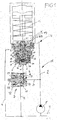
- Fig. 1 schematically illustrates a hydraulic tool W, which is used for example for pressing cable lugs.
- the tool W is expediently a hand tool which can either be connected to the network via a cable or has a rechargeable battery or power pack for a pump P which can be operated electrically in the disconnection mode.
- a pressure line branch 3 leads to the pressure relief valve D, from whose spring chamber a return channel 5 leads to a return line 4 (tank T) connected to the changeover valve U.
- An outlet 6 of the pressure limiting valve D is connected to a pressure port 7 of a large-diameter transmission piston 22 of the switching valve U.
- a piston 8 is slidably guided, which has a central extension 9 which cooperates with a central bore 10 in which the pressure of the pressure line 2, 3 acts on the extension 9.
- the piston 8 has a relative to the extension 9 much larger piston plate 11, which is loaded by a control spring 12.
- a shaft 13 of the piston 8 extends sealed to the outside from the pressure relief valve D and has a mechanical actuator 14, can be attacked for example, to open the pressure relief valve D by hand or a corresponding translation.
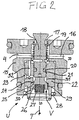
- the switching valve U which is expediently designed as a valve cartridge, preferably screw-in cartridge, has a housing 15 which has a return channel 16 connected to the return 4 and a seat 17 for a valve cone 18.
- the valve cone 18 is acted upon by a closing spring 19 in the closing direction to the seat 17 and is, preferably sealed with a seal 20, slidably guided in a bore 21 of the transmission piston 22.
- the translation piston 22 is in turn in a bore 23 of the housing 15 with slidably guided a slide fitting.
- the slider fit can range between a few hundredths and one or two tenths of a millimeter.
- a seat 24 for a sealing surface 25 of a closing body 26 of a check valve V is formed in the transmission piston 22.
- the closing body 26 is acted upon by a closing spring 27 in the closing direction to the seat 24.
- the closing spring 27 is supported on a stop 28 in the transmission piston 22.
- the stop 28 is for example a transverse pin in a passage of the transmission piston 22.
- the closing body 26 may have at least one lateral flattening 29 to open pressure medium then the way into the passage when the sealing surface 25 is lifted from the seat 24.
- an extension 31, and following the seat 24, a further extension 30 in the transmission piston 22 are provided.
- the extensions 31, 30 together define a Abströmweg in the interior of the transmission piston 22, which Abströmweg leads via connecting holes 32 to the return passage 16 and thus to the return 4.
- Der rublaufkanal 16 ist in der Auslrawötechnisch 32 anesthesia.
- the hydraulic drive H is shown during the return of the tool piston K.
- the reversing valve U is in the open position with the valve 17 lifted off the seat 17.
- the check valve V is in its shut-off position.
- the pressure limiting valve D is in its shut-off position.
- the pump P is not in operation.
- FIG. 1 and 2 an operating situation is shown in which the tool piston K is at the return within the entire return stroke and before reaching an end portion of the return stroke.
- a provided for example on the tool piston K projection 34 is just about to contact the above the seat 17 projecting poppet 18 and to push in the blocking position on the seat 17.
- the pump P is switched off.
- the pressure relief valve D is in the shut-off position. Between the outlet 6 of the pressure relief valve D and the pressure port 7 of the transmission piston 22, a residual pressure from earlier fed in response of the pressure relief valve D pressure holds the translation piston 22 with the check valve V closed in the position shown, in which the valve cone 18 from the seat 17th protrudes, ie the switching valve U is in its open position.
- the pump P is put into operation, so that then closed switching valve U of the working chamber 33 is pressurized and the tool piston K receives its movement against the load 1 until it generates a maximum, preselected tool force.
- the standing in its shut-off pressure relief valve D receives this pressure via the pressure line 3 on the extension 9 in the bore 10.
- the control spring 12 is set to the maximum tool pressure. Once the maximum tool pressure is reached, the piston 8 is displaced against the force of the control spring 12, d. h., The pressure relief valve D is brought into its open position or control position.
- the translation piston 22 does not yield fast enough, as it has a slide bore fit in the bore 23 is guided, or because there is residual pressure at the pressure port 7, then the closing spring 19, the valve cone 18 relative to the translation piston 22 as far down that the check valve V is opened, and the residual pressure on the outflow in the transmission piston 22 to return 4 is reduced.
- the tool piston In the renewed shut-off position of the switching valve 18, the tool piston is either stopped, or it is again moved to a working position after switching the pump P again until finally the maximum tool pressure is reached again and the pressure relief valve D responds to the changeover valve U in the open position bring.
Landscapes
- Engineering & Computer Science (AREA)
- Mechanical Engineering (AREA)
- Physics & Mathematics (AREA)
- Fluid Mechanics (AREA)
- General Engineering & Computer Science (AREA)
- Hand Tools For Fitting Together And Separating, Or Other Hand Tools (AREA)
- Safety Valves (AREA)
Description
- Die Erfindung betrifft einen Hydraulikantrieb gemäß Oberbegriff Patentanspruch 1. Bei dem aus
EP 2835540 A , Fig. 3, bekannten Hydraulikantrieb kann der Werkzeugkolben beim Rücklauf in Offenstellung des Umschaltventils an jeder beliebigen Position dadurch abgestoppt werden, dass die zuvor mit Ansprechen des Druckbegrenzungsventils abgeschaltete Pumpe erneut eingeschaltet wird und einen Druckimpuls erzeugt. Das Umschaltventil enthält einen Ringraum, in welchem der Übersetzungskolben in Schließrichtung des Ventilkegels mit dem Druckimpuls beaufschlagbar ist, um eine im Umschaltventil enthaltene, den Ventilkegel in der Offenstellung festlegende Verrastung zu überwinden und das Umschaltventil in die Sperrstellung einzustellen. Hingegen kann der Rücklauf des Werkzeugkolbens durch Nutzen der mechanischen Betätigung des Druckbegrenzungsventils nicht abgestoppt werden. Es gibt jedoch Anwender, die das Abstoppen des Rücklaufs des Werkzeugkolbens durch Wiedereinschalten der Pumpe als nicht zweckmäßig ansehen, sondern den Werkzeugkolben durch mechanische Betätigung des Druckbegrenzungsventils abzustoppen wünschen. - In dem aus
DE 19825160 A1 bekannten Hydraulikantrieb werden die Umschalt- und Druckbegrenzungs- und Abstoppfunktionen von einem kleinen Fortsatz eines großdurchmessrigen Kolbens und einem engen, dem Fortsatz zugeordneten Sitz einer einzigen, relativ aufwendigen Ventilbaugruppe im Abströmweg vom Arbeitsraum des Werkzeugkolbens zum Rücklauf ausgeführt. Diese Mehrfachfunktionen können aufgrund gegenseitiger Beeinflussung die Funktionssicherheit gefährden. - Der Erfindung liegt die Aufgabe zu Grunde, einen Hydraulikantrieb der eingangs genannten Art anzugeben, bei dem der Rücklauf des Werkzeugkolbens durch eine mechanische Betätigung des Druckbegrenzungsventils abstoppbar ist, sowie das durch mechanische Betätigung des Druckbegrenzungsventils in die Absperrstellung einstellbare Umschaltventil baulich einfach, funktionssicher und kostengünstigist.
- Die gestellte Aufgabe wird mit den Merkmalen des Patentanspruchs 1 gelöst.
- Bei dem Hydraulikantrieb lässt sich trotz des baulich einfachen, funktionssicheren und kostengünstigen Umschaltventils der Rücklauf des Werkzeugkolbens an jeder beliebigen Position innerhalb des gesamten Rücklaufhubs durch eine mechanische Betätigung des Druckbegrenzungsventils abstoppen. Denn der Ventilkegel, der während des Rücklaufs des Werkzeugkolbens in der Offenstellung ist, und z. B. durch zwischen dem Auslass des dann geschlossenen Druckbegrenzungsventils und dem Druckanschluss des Übersetzungskolbens wirksamen Restdruck in der Offenstellung gehalten wird, geht nach mechanischem Öffnen des Druckbegrenzungsventils unter der Wirkung seiner Schließfeder selbsttätig in die Absperrstellung, wodurch der Werkzeugkolben angehalten wird. Durch das Öffnen des Druckbegrenzungsventils wird nämlich der Restdruck abgebaut, der zuvor am Übersetzungskolben wirkte, sodass der Übersetzungskolben und der Ventilkegel, auch unterstützt durch die Strömungsdynamik des aus dem Arbeitsraum des Werkzeugkolbens zum Rücklauf ausgeschobenen Hydraulikmediums, das Umschaltventil in die Absperrstellung bringen. Sollte der Übersetzungskolben z. B. auf Grund des größeren Führungsdurchmessers gegenüber dem Führungsdurchmesser des Ventilkegels in Schließrichtung des Umschaltventils unwillig ansprechen, entsperrt der Ventilkegel das Rückschlagventil, sodass sich der Druck am Druckanschluss durch den Abströmweg zum Rücklauf abbaut. Es ist zum Abstoppen des Rücklaufs des Werkzeugkolbens nicht notwendig, die Pumpe kurzfristig wieder einzuschalten. In dem Umschaltventil halten der mit Schieberpassung im Gehäuse geführte Übersetzungskolben und das im Abströmkanal angeordnete Rückschlagventil in dessen Absperrstellung den Druck am Druckanschluss aufrecht, um das Umschaltventil in der Offenstellung zu halten. Zweckmäßig ist das Umschaltventil als Umschaltventil-Patrone, vorzugsweise Einschraubpatrone, ausgebildet, die direkt am Arbeitsraum des Werkzeugkolbens verbaubar ist.
- Um das Umschaltventil aus der Offenstellung in die Absperrstellung umzustellen, braucht nur der Druck am Druckanschluss abgebaut zu werden, sodass dann der Ventilkegel unter der Kraft seiner Schließfeder in die Absperrstellung am Sitz kommt. Falls der Übersetzungskolben der Bewegung des Ventilkegels zur Absperrstellung des Umschaltventils wegen Restdrucks nicht schnell genug folgen sollte, entsperrt der Ventilkegel das Rückschlagventil im Abströmweg, sodass der Druck am Druckanschluss auch über das dann offene Rückschlagventil zum Rücklauf rasch abgebaut wird. Das Umschaltventil ist baulich einfach, funktionssicher und kostengünstig, u. a. weil es keine Verrastung benötigt und auch keine zusätzliche, mit dem Pumpendruck beaufschlagbare Ringkammer zum Überwinden der Verrastung. Es weist das Rückschlagventil einen im Übersetzungskolben verschiebbar geführten, zweckmäßig federbelasteten, Schließkörper auf, sowie einen im Übersetzungskolben geformten Sitz für den Schließkörper. Der Schließkörper ist entweder durch einen sich in der Funktion des Umschaltventils ergebenden Druckunterschied vom Sitz abhebbar, oder/und durch den relativ zum Übersetzungskolben verstellbar angeordneten Ventilkegel und dessen Schließfeder. Dabei ist es zweckmäßig, wenn die Schließfeder des Schließkörpers schwächer ist als die Schließfeder des Ventilkegels.
- Zweckmäßig wird bei dem Hydraulikantrieb zum wählbaren Abstoppen des Rücklaufs des Werkzeugkolbens innerhalb dessen gesamten Rücklaufhubs in der Offenstellung des Umschaltventils der Ventilkegel durch mechanische Betätigung des Druckbegrenzungsventils, vorzugsweise gleichlaufend mit einer Umstellung des Rückschlagventils in dessen Offenstellung, dadurch in die Absperrstellung gebracht, dass der Ventilkegel durch die Schließfeder assistiert von der Strömungsdynamik des aus dem Arbeitsraum ausgeschobenen Druckmediums selbsttätig in die Absperrstellung am Sitz kommt.
- Besonders wichtig ist es, wenn in der Offenstellung des Umschaltventils der Ventilkegel innerhalb eines Endabschnitts des Rücklaufs des Werkzeugkolbens vom Werkzeugkolben selbst, vorzugsweise durch direkt mechanischen Kontakt, in die Absperrstellung auf den Sitz und gleichzeitig oder nacheilend das Rückschlagventil vom Ventilkegel in die Offenstellung gebracht werden. Denn der Werkzeugkolben kann mit beträchtlicher Geschwindigkeit und Kraft am Ventilkegel anschlagen. Würde dann am Druckanschluss noch Restdruck auf dem Übersetzungskolben wirken, so könnte dieser Restdruck über den dann versperrten Auslass des Druckbegrenzungsventils nicht schnell genug abgebaut werden und hohe mechanische Belastungen im Umschaltventil erzeugen. Da jedoch der Ventilkegel das Rückschlagventil unter dem Einfluss des Werkzeugkolbens entsperrt, kann nach wie vor wirkender Restdruck am Übersetzungskolben unmittelbar zum Rücklauf abgebaut werden und werden mechanische Belastungen zwischen beweglichen Komponenten des Umschaltventils minimiert.
- Damit der im Druckanschluss auf den Übersetzungskolben wirkende Druck das Umschaltventil zuverlässig in der Offenstellung hält, solange der Rücklauf des Werkzeugkolbens nicht gewollt abgestoppt werden soll, ist es zweckmäßig, dass der Übersetzungskolben mit einer Schieberpassung im Gehäuse geführt ist. Die Schieberpassung erlaubt einerseits eine relativ leichtgängige Bewegung des Übersetzungskolbens, unterbindet aber einen unkontrolliert raschen Druckabbau über die Schieberpassung zum Rücklauf. Ein weiterer wichtiger Aspekt besteht darin, dass der Absperrdurchmesser des Rückschlagventils größer ist als der Absperrdurchmesser des Ventilkegels am Sitz. Dieses Größenverhältnis stellt die ordnungsgemäße Funktion des Umschaltventils sicher.
- Die Schließfeder des Schließkörpers, falls überhaupt vorgesehen, ist zweckmäßig in einem im Abströmweg im Übersetzungskolben vorgesehenen Anschlag so abgestützt, dass der Abströmweg dadurch nicht behindert wird.
- Baulich einfach ist der Anschlag ein im Übersetzungskolben angeordneter Querstift.
- Anhand der Zeichnung wird eine Ausführungsform des Erfindungsgegenstandes erläutert. Das zeigen:
-
Fig. 1 ein Blockschaltbild mit im Axialschnitt gezeigten Ausstattungskomponenten eines Hydraulikantriebs eines Werkzeugs, und -
Fig. 2 eine vergrößerte Axialschnittdarstellung eines inFig. 1 gezeigten Umschaltventils. -
Fig. 1 verdeutlicht schematisch ein hydraulisches Werkzeug W, das beispielsweise zum Verpressen von Kabelschuhen benutzt wird. Das Werkzeug W ist zweckmäßig ein Handwerkzeug, das entweder über ein Kabel an das Netz anschließbar ist oder einen Akku oder Powerpack für eine elektrisch im Abschaltbetrieb betreibbare Pumpe P aufweist. - Ein Werkzeugkolben K ist über eine Druckleitung 2 in einem Arbeitsraum 33 gegen eine Last 1 (z. B. eine Rückstellfeder) zwischen einer voll zurückgezogenen, gezeigten Stellung und einer mit Druck in der Druckleitung 2 verfahrenen Stellung bewegbar, in der maximaler Werkzeugdruck erzeugt ist. Dieser maximale Werkzeugdruck wird durch ein Druckbegrenzungsventil D begrenzt. Die Umstellung zwischen dem Verfahren des Arbeitskolbens K gegen die Last 1 und dem Rücklauf des Werkzeugkolbens K nach Ansprechen des Druckbegrenzungsventils D wird von einem Umschaltventil U gesteuert, das direkt beim Arbeitsraum 3 verbaut sein kann.
- Von der Druckleitung 2 führt ein Druckleitungszweig 3 zum Druckbegrenzungsventil D, von dessen Federraum ein Rücklaufkanal 5 zu einem an das Umschaltventil U angeschlossenen Rücklauf 4 (Tank T) führt.
- Ein Auslass 6 des Druckbegrenzungsventils D ist mit einem Druckanschluss 7 eines großdurchmessigen Übersetzungskolbens 22 des Umschaltventils U verbunden.
- Im Druckbegrenzungsventil D ist ein Kolben 8 verschiebbar geführt, der einen zentralen Fortsatz 9 aufweist, der mit einer zentralen Bohrung 10 zusammenwirkt, in welcher der Druck der Druckleitung 2, 3 auf den Fortsatz 9 wirkt. Der Kolben 8 hat eine gegenüber dem Fortsatz 9 wesentlich größeren Kolbenteller 11, der durch eine Regelfeder 12 belastet wird. Ein Schaft 13 des Kolbens 8 erstreckt sich abgedichtet nach außen aus dem Druckbegrenzungsventil D und weist eine mechanische Betätigung 14 auf, an der beispielsweise zum Öffnen des Druckbegrenzungsventils D von Hand oder über eine entsprechende Übersetzung angegriffen werden kann.
- Das Umschaltventil U, das zweckmäßig als Ventilpatrone, vorzugsweise Einschraubpatrone, ausgebildet ist, weist ein Gehäuse 15 auf, das einen an den Rücklauf 4 angeschlossenen Rücklaufkanal 16 und einen Sitz 17 für einen Ventilkegel 18 aufweist. Der Ventilkegel 18 wird durch eine Schließfeder 19 in Schließrichtung zum Sitz 17 beaufschlagt und ist, vorzugsweise mit einer Dichtung 20 abgedichtet, in einer Bohrung 21 des Übersetzungskolbens 22 verschiebbar geführt. Der Übersetzungskolben 22 ist seinerseits in einer Bohrung 23 des Gehäuses 15 mit einer Schieberpassung verschiebbar geführt. Die Schieberpassung kann in einem Bereich zwischen einigen Hundertsteln und einem oder zwei Zehnteln eines Millimeters liegen.
- Im Übersetzungskolben 22 ist ein Sitz 24 für eine Dichtfläche 25 eines Schließkörpers 26 eines Rückschlagventils V gebildet. Der Schließkörper 26 wird durch eine Schließfeder 27 in Schließrichtung zum Sitz 24 beaufschlagt. Die Schließfeder 27 stützt sich an einem Anschlag 28 im Übersetzungskolben 22 ab. Der Anschlag 28 ist beispielsweise ein Querstift in einem Durchgang des Übersetzungskolbens 22. Der Schließkörper 26 kann wenigstens eine seitliche Abflachung 29 aufweisen, um Druckmittel dann den Weg in den Durchgang zu öffnen, wenn die Dichtfläche 25 vom Sitz 24 abgehoben ist.
- Im Anschluss an die Bohrung 21 sind eine Erweiterung 31, und im Anschluss an den Sitz 24 eine weitere Erweiterung 30 im Übersetzungskolben 22 vorgesehen. Die Erweiterungen 31, 30 definieren gemeinsam einen Abströmweg im Inneren des Übersetzungskolbens 22, welcher Abströmweg über Verbindungsbohrungen 32 zum Rücklaufkanal 16 und somit zum Rücklauf 4 führt.
- In den
Fig. 1 und2 ist der Hydraulikantrieb H beim Rücklauf des Werkzeugkolbens K gezeigt. Das Umschaltventil U befindet sich in der Offenstellung mit vom Sitz 17 abgehobenem Ventilkegel 18. Das Rückschlagventil V ist in seiner Absperrstellung. Das Druckbegrenzungsventil D ist in seiner Absperrstellung. Die Pumpe P ist nicht im Betrieb. - In den
Fig. 1 und2 ist eine Betriebssituation gezeigt, in welcher sich der Werkzeugkolben K beim Rücklauf innerhalb des gesamten Rücklaufhubs und noch vor Erreichen eines Endabschnitts des Rücklaufhubs befindet. Ein beispielsweise am Werkzeugkolben K vorgesehener Vorsprung 34 ist gerade im Begriff, den über den Sitz 17 vorstehenden Ventilkegel 18 zu kontaktieren und in die Sperrstellung am Sitz 17 zu schieben. Die Pumpe P ist abgeschaltet. Das Druckbegrenzungsventil D befindet sich in der Absperrstellung. Zwischen dem Auslass 6 des Druckbegrenzungsventils D und dem Druckanschluss 7 des Übersetzungskolbens 22 wirkt ein Restdruck aus früher beim Ansprechen des Druckbegrenzungsventils D eingespeistem Druck, der den Übersetzungskolben 22 bei geschlossenem Rückschlagventil V in der gezeigten Stellung hält, in welcher der Ventilkegel 18 aus dem Sitz 17 vorsteht, d. h. das Umschaltventil U in seiner Offenstellung ist. - Wird der Werkzeugkolben K unter der Last 1 weiter in Richtung nach unten in
Fig. 1 bis zu seiner Endstellung verschoben, gelangt der Fortsatz 34 in Kontakt mit dem Ventilkegel 18 und wird der Ventilkegel 18 auf den Sitz 17 gedrückt. Das Umschaltventil U ist dann in der Absperrstellung. - Sollte weiterhin am Druckanschluss 7 Restdruck herrschen, der den Übersetzungskolben 22 in der gezeigten Position hält, dann drückt der Ventilkegel 18 den Schließkörper 26 vom Sitz 24 weg und wird dieser Druck auf dem Übersetzungskolben 22 zum Rücklauf 4 abgebaut, und zwar über den inneren Abströmweg im Übersetzungskolben 22, der demzufolge seine Bewegung mit dem Ventilkegel 18 aufnimmt, zumindest so weit, bis nach Abbau des Restdrucks die Schließfeder 27 das Rückschlagventil V wieder in die gezeigte Absperrstellung bringt.
- Für einen neuen Arbeitsvorgang wird die Pumpe P in Betrieb gesetzt, sodass bei dann geschlossenem Umschaltventil U der Arbeitsraum 33 druckbeaufschlagt wird und der Werkzeugkolben K seine Bewegung gegen die Last 1 aufnimmt, bis er eine maximale, vorgewählte Werkzeugkraft erzeugt. Das in seiner Absperrstellung stehende Druckbegrenzungsventil D erhält diesen Druck über die Druckleitung 3 auf dem Fortsatz 9 in der Bohrung 10. Die Regelfeder 12 ist auf den maximalen Werkzeugdruck eingestellt. Sobald der maximale Werkzeugdruck erreicht wird, wird der Kolben 8 gegen die Kraft der Regelfeder 12 verlagert, d. h., das Druckbegrenzungsventil D wird in seine Offenstellung bzw. Regelstellung gebracht.
- Mit dem Ansprechen des Druckbegrenzungsventils D wird die Pumpe P abgeschaltet. Durch das Ansprechen des Druckbegrenzungsventils D (einige Zehntel Millimeter Öffnungshub) wird der große Kolbenteller 11 beaufschlagt, der den Kolben 8 mindestens einen Millimeter anhebt und hält. Dadurch wird am Auslass 6 ein Druckimpuls erzeugt und Druck aufgebaut, der am Druckanschluss 7 auf den Übersetzungskolben 22 (und den Schließkörper 26) einwirkt und diesen in die in
Fig. 1 gezeigte Stellung verschiebt, in welcher das Umschaltventil U seine Offenstellung einnimmt. Daraufhin schiebt die Last 1 den Werkzeugkolben K nach unten und wird Druckmittel über das dann offene Umschaltventil U in den Rücklauf 4 ausgeschoben. Sich im Raum der Regelfeder 12 des Druckbegrenzungsventils D aufbauender Druck wird über die Rücklaufleitung 5 abgebaut. Der Werkzeugkolben K kehrt in seine Endstellung zurück, in der er das Umschaltventil U wieder in die Absperrstellung stellt. - Sollte jedoch innerhalb des möglichen Rücklaufhubs des Werkzeugkolbens K gewünscht werden, den Werkzeugkolben K zu stoppen, dann wird an der mechanischen Betätigung 14 des Druckbegrenzungsventils D angegriffen und dieses zumindest vorübergehen in die Offenstellung verstellt. Dadurch baut sich der Druck am Druckanschluss 7 über die dann zumindest weitestgehend drucklose Druckleitung 2, 3, das offene Umschaltventil U und den Rücklauf 4 zum Tank T ab und wird der Übersetzungskolben 22 zusammen mit dem Ventilkegel 18 in den Figuren nach unten verstellt, bis der Ventilkegel 18 auf den Sitz 17 aufliegt, und der Werkzeugkolben K an einer weiteren Rücklaufbewegung gehindert ist. Sollte der Übersetzungskolben 22 nicht schnell genug nachgeben, da er mit einer Schieberbohrungspassung in der Bohrung 23 geführt ist, oder weil am Druckanschluss 7 noch Restdruck herrscht, dann stellt die Schließfeder 19 den Ventilkegel 18 relativ zum Übersetzungskolben 22 soweit nach unten, dass das Rückschlagventil V geöffnet wird, und der Restdruck über den Abströmweg im Übersetzungskolben 22 zum Rücklauf 4 abgebaut wird.
- In der erneuten Absperrstellung des Umschaltventils 18 wird der Werkzeugkolben entweder angehalten, oder wird er nach erneutem Einschalten der Pumpe P wieder zu einer Arbeitsposition bewegt, bis schließlich erneut der maximale Werkzeugdruck erreicht ist und das Druckbegrenzungsventil D anspricht, um das Umschaltventil U in die Offenstellung zu bringen.
Claims (6)
- Hydraulikantrieb (H) mit einer Pumpe (P), einem einseitig über die im Abschaltbetrieb laufende Pumpe (P) gegen eine Last (1) verstellbaren Werkzeugkolben (K), und mit einem maximalen Werkzeugdruck des Werkzeugkolbens (K) begrenzenden, eine mechanische Betätigung (14) aufweisenden Druckbegrenzungsventil (D) sowie einem in Absperr- und Offenstellungen einstellbaren Umschaltventil (U) zwischen einem an die Pumpe (P) angeschlossenen Arbeitsraum (33) des Werkzeugkolbens (K) und einem Rücklauf (4), wobei ein Auslass (6) des Druckbegrenzungsventils (D) mit einem Druckanschluss (7) eines einen Ventilkegel (18) des Umschaltventils (U) enthaltenden Übersetzungskolbens (22) des Umschaltventils (U) verbunden ist, dadurch gekennzeichnet, dass innen im Übersetzungskolben (22) des vom Druckbegrenzungsventil (D) getrennten Umschaltventils (U) ein Abströmweg vom Druckanschluss (7) zum Rücklauf (4) angeordnet ist, dass der Übersetzungskolben (22) ein in Strömungsrichtung vom Druckanschluss (7) zum Rücklauf (4) sperrendes Rückschlagventil (V) mit einem Schließkörper (26) enthält, das einen im Übersetzungskolben (22) geformten Sitz (24) für den Schließkörper (26) aufweist, wobei der Schließkörper (26) zum Entsperren des Rückschlagventils (V) druckabhängig und/oder durch den relativ zum Übersetzungskolben (22) verstellten Ventilkegel (18) vom Sitz (24) abhebbar ist, und dass der Ventilkegel (18) in Schließrichtung durch eine Schließfeder (19) belastet ist.
- Hydraulikantrieb nach Anspruch 1, dadurch gekennzeichnet, dass zum wählbaren Abstoppen des Rücklaufs des Werkzeugkolbens (K) innerhalb dessen Rücklaufhub in der Offenstellung des Umschaltventils (U) der Ventilkegel (18) durch mechanische Betätigung des Druckbegrenzungsventils (D), vorzugsweise mit Umstellen des Rückschlagventils (V) in dessen Offenstellung, über die Schließfeder (19) in die Absperrstellung bringbar ist.
- Hydraulikantrieb nach Anspruch 1, dadurch gekennzeichnet, dass in Offenstellung des Umschaltventils (U) der Ventilkegel (18) innerhalb eines Endabschnitts des Rücklaufs des Werkzeugkolbens (K) vom Werkzeugkolben (K), vorzugsweise mechanisch, in die Absperrstellung des Umschaltventils (U) und das Rückschlagventil (V) vom Ventilkegel (18) in die Offenstellung bringbar sind.
- Hydraulikantrieb nach Anspruch 1, dadurch gekennzeichnet, dass der Absperrdurchmesser des Rückschlagventils (V) größer ist als der Absperrdurchmesser des Ventilkegels (18).
- Hydraulikantrieb nach Anspruch 1, dadurch gekennzeichnet, dass eine Schließfeder (27) des Schließkörpers (26) an einem im Abströmweg im Übersetzungskolben (22) vorgesehenen Anschlag (28) abgestützt ist.
- Hydraulikantrieb nach Anspruch 5, dadurch gekennzeichnet, dass der Anschlag (28) ein im Übersetzungskolben (22) angeordneter Querstift ist.
Priority Applications (1)
| Application Number | Priority Date | Filing Date | Title |
|---|---|---|---|
| EP15163170.2A EP3078456B1 (de) | 2015-04-10 | 2015-04-10 | Hydraulikantrieb |
Applications Claiming Priority (1)
| Application Number | Priority Date | Filing Date | Title |
|---|---|---|---|
| EP15163170.2A EP3078456B1 (de) | 2015-04-10 | 2015-04-10 | Hydraulikantrieb |
Publications (2)
| Publication Number | Publication Date |
|---|---|
| EP3078456A1 EP3078456A1 (de) | 2016-10-12 |
| EP3078456B1 true EP3078456B1 (de) | 2017-12-06 |
Family
ID=52997215
Family Applications (1)
| Application Number | Title | Priority Date | Filing Date |
|---|---|---|---|
| EP15163170.2A Active EP3078456B1 (de) | 2015-04-10 | 2015-04-10 | Hydraulikantrieb |
Country Status (1)
| Country | Link |
|---|---|
| EP (1) | EP3078456B1 (de) |
Cited By (1)
| Publication number | Priority date | Publication date | Assignee | Title |
|---|---|---|---|---|
| EP4582699A1 (de) * | 2024-01-04 | 2025-07-09 | Enerpac Tool Group Corp. | Ventile zur steuerung des durchflusses einer unter druck stehenden flüssigkeit zu einem werkzeug |
Family Cites Families (3)
| Publication number | Priority date | Publication date | Assignee | Title |
|---|---|---|---|---|
| DE19825160A1 (de) * | 1997-10-15 | 1999-04-22 | Klauke Gmbh Gustav | Hydraulisches Preßgerät und Verfahren zum Betreiben desselben |
| EP2711560B1 (de) * | 2012-09-21 | 2019-06-12 | HAWE Hydraulik SE | Hydraulikantrieb für ein hydraulisch betätigbares Werkzeug |
| EP2835540B1 (de) | 2013-08-08 | 2016-04-27 | HAWE Hydraulik SE | Hydraulikantrieb |
-
2015
- 2015-04-10 EP EP15163170.2A patent/EP3078456B1/de active Active
Non-Patent Citations (1)
| Title |
|---|
| None * |
Cited By (2)
| Publication number | Priority date | Publication date | Assignee | Title |
|---|---|---|---|---|
| EP4582699A1 (de) * | 2024-01-04 | 2025-07-09 | Enerpac Tool Group Corp. | Ventile zur steuerung des durchflusses einer unter druck stehenden flüssigkeit zu einem werkzeug |
| US12618485B2 (en) | 2024-01-04 | 2026-05-05 | Enerpac Tool Group Corp. | Valves for controlling flow of pressurized fluid to a tool |
Also Published As
| Publication number | Publication date |
|---|---|
| EP3078456A1 (de) | 2016-10-12 |
Similar Documents
| Publication | Publication Date | Title |
|---|---|---|
| WO2008095549A1 (de) | Verfahren und vorrichtung zur steuerung einer gas-hochdruck-feuerlöschanlage | |
| DE1576088A1 (de) | Schnellentlastungsventil fuer hydraulische Kraftzylinder | |
| DE102008031745A1 (de) | Hydraulische Ventilvorrichtung | |
| EP1781952B1 (de) | Hydraulische steueranordnung | |
| DE2338267A1 (de) | Zweistufiger pneumatisch-hydraulischer booster | |
| EP2835540B1 (de) | Hydraulikantrieb | |
| DE1750413C3 (de) | Steuerventil | |
| DE102014016639A1 (de) | Hydraulikventilanordnung mit Steuerungs-/Regelungsfunktion | |
| DE19833489A1 (de) | Hydraulische Schaltung | |
| WO2003102427A1 (de) | Hydrozylinder mit ventilanordnung | |
| EP3078456A1 (de) | Hydraulikantrieb und umschaltventil | |
| DE102021208932B3 (de) | Stabilisierungsmodul | |
| DE3243182C2 (de) | ||
| DE3006530A1 (de) | Hydraulisches blockier- oder halteventil | |
| DE19705827A1 (de) | Hydrauliksysteme | |
| DE2735558A1 (de) | Steuergeraet fuer hydraulische arbeitsgeraete | |
| DE2104362A1 (de) | Druckventil fuer hydraulische anlagen | |
| DE4002755A1 (de) | Ventilanordnung zur steuerung der zufuhr von fluid zu zwei verbrauchern | |
| EP1875084A1 (de) | Wegeventil und damit ausgeführte ls-steueranordnung | |
| DE102016213820B3 (de) | Ventil | |
| AT516317B1 (de) | Hydraulische Schaltung zur Versorgung eines Verbrauchers mit Differentialcharakter | |
| EP2674626B1 (de) | Hydraulikschaltung | |
| DE10341356B4 (de) | Vorspannventil mit zumindest zwei Schaltstufen sowie hydraulische Betätigungsanordnung | |
| EP1510699B1 (de) | Verfahren und Vorrichtung zur Flutumschaltung | |
| DE2318880A1 (de) | Ventil mit stillegungsvorrichtung |
Legal Events
| Date | Code | Title | Description |
|---|---|---|---|
| PUAI | Public reference made under article 153(3) epc to a published international application that has entered the european phase |
Free format text: ORIGINAL CODE: 0009012 |
|
| 17P | Request for examination filed |
Effective date: 20151127 |
|
| AK | Designated contracting states |
Kind code of ref document: A1 Designated state(s): AL AT BE BG CH CY CZ DE DK EE ES FI FR GB GR HR HU IE IS IT LI LT LU LV MC MK MT NL NO PL PT RO RS SE SI SK SM TR |
|
| AX | Request for extension of the european patent |
Extension state: BA ME |
|
| GRAP | Despatch of communication of intention to grant a patent |
Free format text: ORIGINAL CODE: EPIDOSNIGR1 |
|
| STAA | Information on the status of an ep patent application or granted ep patent |
Free format text: STATUS: GRANT OF PATENT IS INTENDED |
|
| INTG | Intention to grant announced |
Effective date: 20170622 |
|
| GRAS | Grant fee paid |
Free format text: ORIGINAL CODE: EPIDOSNIGR3 |
|
| GRAA | (expected) grant |
Free format text: ORIGINAL CODE: 0009210 |
|
| STAA | Information on the status of an ep patent application or granted ep patent |
Free format text: STATUS: THE PATENT HAS BEEN GRANTED |
|
| AK | Designated contracting states |
Kind code of ref document: B1 Designated state(s): AL AT BE BG CH CY CZ DE DK EE ES FI FR GB GR HR HU IE IS IT LI LT LU LV MC MK MT NL NO PL PT RO RS SE SI SK SM TR |
|
| REG | Reference to a national code |
Ref country code: GB Ref legal event code: FG4D Free format text: NOT ENGLISH |
|
| REG | Reference to a national code |
Ref country code: AT Ref legal event code: REF Ref document number: 951966 Country of ref document: AT Kind code of ref document: T Effective date: 20171215 Ref country code: CH Ref legal event code: EP |
|
| REG | Reference to a national code |
Ref country code: IE Ref legal event code: FG4D Free format text: LANGUAGE OF EP DOCUMENT: GERMAN |
|
| REG | Reference to a national code |
Ref country code: DE Ref legal event code: R096 Ref document number: 502015002475 Country of ref document: DE |
|
| REG | Reference to a national code |
Ref country code: CH Ref legal event code: NV Representative=s name: TROESCH SCHEIDEGGER WERNER AG, CH |
|
| RAP2 | Party data changed (patent owner data changed or rights of a patent transferred) |
Owner name: HAWE HYDRAULIK SE |
|
| REG | Reference to a national code |
Ref country code: NL Ref legal event code: MP Effective date: 20171206 |
|
| REG | Reference to a national code |
Ref country code: LT Ref legal event code: MG4D |
|
| PG25 | Lapsed in a contracting state [announced via postgrant information from national office to epo] |
Ref country code: SE Free format text: LAPSE BECAUSE OF FAILURE TO SUBMIT A TRANSLATION OF THE DESCRIPTION OR TO PAY THE FEE WITHIN THE PRESCRIBED TIME-LIMIT Effective date: 20171206 Ref country code: LT Free format text: LAPSE BECAUSE OF FAILURE TO SUBMIT A TRANSLATION OF THE DESCRIPTION OR TO PAY THE FEE WITHIN THE PRESCRIBED TIME-LIMIT Effective date: 20171206 Ref country code: ES Free format text: LAPSE BECAUSE OF FAILURE TO SUBMIT A TRANSLATION OF THE DESCRIPTION OR TO PAY THE FEE WITHIN THE PRESCRIBED TIME-LIMIT Effective date: 20171206 Ref country code: FI Free format text: LAPSE BECAUSE OF FAILURE TO SUBMIT A TRANSLATION OF THE DESCRIPTION OR TO PAY THE FEE WITHIN THE PRESCRIBED TIME-LIMIT Effective date: 20171206 Ref country code: NO Free format text: LAPSE BECAUSE OF FAILURE TO SUBMIT A TRANSLATION OF THE DESCRIPTION OR TO PAY THE FEE WITHIN THE PRESCRIBED TIME-LIMIT Effective date: 20180306 |
|
| REG | Reference to a national code |
Ref country code: DE Ref legal event code: R082 Ref document number: 502015002475 Country of ref document: DE Representative=s name: GROSSE, SCHUMACHER, KNAUER, VON HIRSCHHAUSEN, DE Ref country code: DE Ref legal event code: R081 Ref document number: 502015002475 Country of ref document: DE Owner name: HAWE HYDRAULIK SE, DE Free format text: FORMER OWNER: HAWE HYDRAULIK SE, 81673 MUENCHEN, DE |
|
| PG25 | Lapsed in a contracting state [announced via postgrant information from national office to epo] |
Ref country code: GR Free format text: LAPSE BECAUSE OF FAILURE TO SUBMIT A TRANSLATION OF THE DESCRIPTION OR TO PAY THE FEE WITHIN THE PRESCRIBED TIME-LIMIT Effective date: 20180307 Ref country code: BG Free format text: LAPSE BECAUSE OF FAILURE TO SUBMIT A TRANSLATION OF THE DESCRIPTION OR TO PAY THE FEE WITHIN THE PRESCRIBED TIME-LIMIT Effective date: 20180306 Ref country code: LV Free format text: LAPSE BECAUSE OF FAILURE TO SUBMIT A TRANSLATION OF THE DESCRIPTION OR TO PAY THE FEE WITHIN THE PRESCRIBED TIME-LIMIT Effective date: 20171206 Ref country code: RS Free format text: LAPSE BECAUSE OF FAILURE TO SUBMIT A TRANSLATION OF THE DESCRIPTION OR TO PAY THE FEE WITHIN THE PRESCRIBED TIME-LIMIT Effective date: 20171206 Ref country code: HR Free format text: LAPSE BECAUSE OF FAILURE TO SUBMIT A TRANSLATION OF THE DESCRIPTION OR TO PAY THE FEE WITHIN THE PRESCRIBED TIME-LIMIT Effective date: 20171206 |
|
| PG25 | Lapsed in a contracting state [announced via postgrant information from national office to epo] |
Ref country code: NL Free format text: LAPSE BECAUSE OF FAILURE TO SUBMIT A TRANSLATION OF THE DESCRIPTION OR TO PAY THE FEE WITHIN THE PRESCRIBED TIME-LIMIT Effective date: 20171206 |
|
| PG25 | Lapsed in a contracting state [announced via postgrant information from national office to epo] |
Ref country code: SK Free format text: LAPSE BECAUSE OF FAILURE TO SUBMIT A TRANSLATION OF THE DESCRIPTION OR TO PAY THE FEE WITHIN THE PRESCRIBED TIME-LIMIT Effective date: 20171206 Ref country code: CZ Free format text: LAPSE BECAUSE OF FAILURE TO SUBMIT A TRANSLATION OF THE DESCRIPTION OR TO PAY THE FEE WITHIN THE PRESCRIBED TIME-LIMIT Effective date: 20171206 Ref country code: EE Free format text: LAPSE BECAUSE OF FAILURE TO SUBMIT A TRANSLATION OF THE DESCRIPTION OR TO PAY THE FEE WITHIN THE PRESCRIBED TIME-LIMIT Effective date: 20171206 |
|
| PG25 | Lapsed in a contracting state [announced via postgrant information from national office to epo] |
Ref country code: SM Free format text: LAPSE BECAUSE OF FAILURE TO SUBMIT A TRANSLATION OF THE DESCRIPTION OR TO PAY THE FEE WITHIN THE PRESCRIBED TIME-LIMIT Effective date: 20171206 Ref country code: PL Free format text: LAPSE BECAUSE OF FAILURE TO SUBMIT A TRANSLATION OF THE DESCRIPTION OR TO PAY THE FEE WITHIN THE PRESCRIBED TIME-LIMIT Effective date: 20171206 |
|
| REG | Reference to a national code |
Ref country code: DE Ref legal event code: R097 Ref document number: 502015002475 Country of ref document: DE |
|
| PG25 | Lapsed in a contracting state [announced via postgrant information from national office to epo] |
Ref country code: MT Free format text: LAPSE BECAUSE OF FAILURE TO SUBMIT A TRANSLATION OF THE DESCRIPTION OR TO PAY THE FEE WITHIN THE PRESCRIBED TIME-LIMIT Effective date: 20171206 |
|
| PLBE | No opposition filed within time limit |
Free format text: ORIGINAL CODE: 0009261 |
|
| STAA | Information on the status of an ep patent application or granted ep patent |
Free format text: STATUS: NO OPPOSITION FILED WITHIN TIME LIMIT |
|
| 26N | No opposition filed |
Effective date: 20180907 |
|
| PG25 | Lapsed in a contracting state [announced via postgrant information from national office to epo] |
Ref country code: MC Free format text: LAPSE BECAUSE OF FAILURE TO SUBMIT A TRANSLATION OF THE DESCRIPTION OR TO PAY THE FEE WITHIN THE PRESCRIBED TIME-LIMIT Effective date: 20171206 Ref country code: DK Free format text: LAPSE BECAUSE OF FAILURE TO SUBMIT A TRANSLATION OF THE DESCRIPTION OR TO PAY THE FEE WITHIN THE PRESCRIBED TIME-LIMIT Effective date: 20171206 Ref country code: SI Free format text: LAPSE BECAUSE OF FAILURE TO SUBMIT A TRANSLATION OF THE DESCRIPTION OR TO PAY THE FEE WITHIN THE PRESCRIBED TIME-LIMIT Effective date: 20171206 |
|
| REG | Reference to a national code |
Ref country code: BE Ref legal event code: MM Effective date: 20180430 |
|
| REG | Reference to a national code |
Ref country code: IE Ref legal event code: MM4A |
|
| PG25 | Lapsed in a contracting state [announced via postgrant information from national office to epo] |
Ref country code: LU Free format text: LAPSE BECAUSE OF NON-PAYMENT OF DUE FEES Effective date: 20180410 |
|
| PG25 | Lapsed in a contracting state [announced via postgrant information from national office to epo] |
Ref country code: BE Free format text: LAPSE BECAUSE OF NON-PAYMENT OF DUE FEES Effective date: 20180430 |
|
| PG25 | Lapsed in a contracting state [announced via postgrant information from national office to epo] |
Ref country code: FR Free format text: LAPSE BECAUSE OF NON-PAYMENT OF DUE FEES Effective date: 20180430 Ref country code: IE Free format text: LAPSE BECAUSE OF NON-PAYMENT OF DUE FEES Effective date: 20180410 |
|
| PGFP | Annual fee paid to national office [announced via postgrant information from national office to epo] |
Ref country code: IT Payment date: 20190521 Year of fee payment: 14 |
|
| GBPC | Gb: european patent ceased through non-payment of renewal fee |
Effective date: 20190410 |
|
| PG25 | Lapsed in a contracting state [announced via postgrant information from national office to epo] |
Ref country code: GB Free format text: LAPSE BECAUSE OF NON-PAYMENT OF DUE FEES Effective date: 20190410 |
|
| PG25 | Lapsed in a contracting state [announced via postgrant information from national office to epo] |
Ref country code: TR Free format text: LAPSE BECAUSE OF FAILURE TO SUBMIT A TRANSLATION OF THE DESCRIPTION OR TO PAY THE FEE WITHIN THE PRESCRIBED TIME-LIMIT Effective date: 20171206 |
|
| PG25 | Lapsed in a contracting state [announced via postgrant information from national office to epo] |
Ref country code: PT Free format text: LAPSE BECAUSE OF FAILURE TO SUBMIT A TRANSLATION OF THE DESCRIPTION OR TO PAY THE FEE WITHIN THE PRESCRIBED TIME-LIMIT Effective date: 20171206 |
|
| PG25 | Lapsed in a contracting state [announced via postgrant information from national office to epo] |
Ref country code: MK Free format text: LAPSE BECAUSE OF NON-PAYMENT OF DUE FEES Effective date: 20171206 Ref country code: CY Free format text: LAPSE BECAUSE OF FAILURE TO SUBMIT A TRANSLATION OF THE DESCRIPTION OR TO PAY THE FEE WITHIN THE PRESCRIBED TIME-LIMIT Effective date: 20171206 Ref country code: HU Free format text: LAPSE BECAUSE OF FAILURE TO SUBMIT A TRANSLATION OF THE DESCRIPTION OR TO PAY THE FEE WITHIN THE PRESCRIBED TIME-LIMIT; INVALID AB INITIO Effective date: 20150410 Ref country code: RO Free format text: LAPSE BECAUSE OF FAILURE TO SUBMIT A TRANSLATION OF THE DESCRIPTION OR TO PAY THE FEE WITHIN THE PRESCRIBED TIME-LIMIT Effective date: 20171206 |
|
| PG25 | Lapsed in a contracting state [announced via postgrant information from national office to epo] |
Ref country code: AL Free format text: LAPSE BECAUSE OF FAILURE TO SUBMIT A TRANSLATION OF THE DESCRIPTION OR TO PAY THE FEE WITHIN THE PRESCRIBED TIME-LIMIT Effective date: 20171206 Ref country code: IS Free format text: LAPSE BECAUSE OF FAILURE TO SUBMIT A TRANSLATION OF THE DESCRIPTION OR TO PAY THE FEE WITHIN THE PRESCRIBED TIME-LIMIT Effective date: 20180406 |
|
| REG | Reference to a national code |
Ref country code: AT Ref legal event code: MM01 Ref document number: 951966 Country of ref document: AT Kind code of ref document: T Effective date: 20200410 |
|
| PG25 | Lapsed in a contracting state [announced via postgrant information from national office to epo] |
Ref country code: AT Free format text: LAPSE BECAUSE OF NON-PAYMENT OF DUE FEES Effective date: 20200410 |
|
| PG25 | Lapsed in a contracting state [announced via postgrant information from national office to epo] |
Ref country code: IT Free format text: LAPSE BECAUSE OF NON-PAYMENT OF DUE FEES Effective date: 20200410 |
|
| P01 | Opt-out of the competence of the unified patent court (upc) registered |
Effective date: 20230523 |
|
| PGFP | Annual fee paid to national office [announced via postgrant information from national office to epo] |
Ref country code: CH Payment date: 20240501 Year of fee payment: 10 |
|
| REG | Reference to a national code |
Ref country code: CH Ref legal event code: H13 Free format text: ST27 STATUS EVENT CODE: U-0-0-H10-H13 (AS PROVIDED BY THE NATIONAL OFFICE) Effective date: 20251125 |
|
| PG25 | Lapsed in a contracting state [announced via postgrant information from national office to epo] |
Ref country code: CH Free format text: LAPSE BECAUSE OF NON-PAYMENT OF DUE FEES Effective date: 20250430 |
|
| PGFP | Annual fee paid to national office [announced via postgrant information from national office to epo] |
Ref country code: DE Payment date: 20260421 Year of fee payment: 12 |