EP3078478B1 - Dispositif de chauffage destine au rechauffement d'une feuille - Google Patents
Dispositif de chauffage destine au rechauffement d'une feuille Download PDFInfo
- Publication number
- EP3078478B1 EP3078478B1 EP16152933.4A EP16152933A EP3078478B1 EP 3078478 B1 EP3078478 B1 EP 3078478B1 EP 16152933 A EP16152933 A EP 16152933A EP 3078478 B1 EP3078478 B1 EP 3078478B1
- Authority
- EP
- European Patent Office
- Prior art keywords
- heating
- plate
- recesses
- heating plate
- heating apparatus
- Prior art date
- Legal status (The legal status is an assumption and is not a legal conclusion. Google has not performed a legal analysis and makes no representation as to the accuracy of the status listed.)
- Active
Links
Images




Classifications
-
- B—PERFORMING OPERATIONS; TRANSPORTING
- B29—WORKING OF PLASTICS; WORKING OF SUBSTANCES IN A PLASTIC STATE IN GENERAL
- B29C—SHAPING OR JOINING OF PLASTICS; SHAPING OF MATERIAL IN A PLASTIC STATE, NOT OTHERWISE PROVIDED FOR; AFTER-TREATMENT OF THE SHAPED PRODUCTS, e.g. REPAIRING
- B29C51/00—Shaping by thermoforming, i.e. shaping sheets or sheet like preforms after heating, e.g. shaping sheets in matched moulds or by deep-drawing; Apparatus therefor
- B29C51/26—Component parts, details or accessories; Auxiliary operations
- B29C51/42—Heating or cooling
- B29C51/421—Heating or cooling of preforms, specially adapted for thermoforming
- B29C51/422—Heating or cooling of preforms, specially adapted for thermoforming to produce a temperature differential
-
- B—PERFORMING OPERATIONS; TRANSPORTING
- B29—WORKING OF PLASTICS; WORKING OF SUBSTANCES IN A PLASTIC STATE IN GENERAL
- B29B—PREPARATION OR PRETREATMENT OF THE MATERIAL TO BE SHAPED; MAKING GRANULES OR PREFORMS; RECOVERY OF PLASTICS OR OTHER CONSTITUENTS OF WASTE MATERIAL CONTAINING PLASTICS
- B29B13/00—Conditioning or physical treatment of the material to be shaped
- B29B13/02—Conditioning or physical treatment of the material to be shaped by heating
- B29B13/023—Half-products, e.g. films, plates
-
- B—PERFORMING OPERATIONS; TRANSPORTING
- B29—WORKING OF PLASTICS; WORKING OF SUBSTANCES IN A PLASTIC STATE IN GENERAL
- B29C—SHAPING OR JOINING OF PLASTICS; SHAPING OF MATERIAL IN A PLASTIC STATE, NOT OTHERWISE PROVIDED FOR; AFTER-TREATMENT OF THE SHAPED PRODUCTS, e.g. REPAIRING
- B29C51/00—Shaping by thermoforming, i.e. shaping sheets or sheet like preforms after heating, e.g. shaping sheets in matched moulds or by deep-drawing; Apparatus therefor
- B29C51/18—Thermoforming apparatus
-
- B—PERFORMING OPERATIONS; TRANSPORTING
- B29—WORKING OF PLASTICS; WORKING OF SUBSTANCES IN A PLASTIC STATE IN GENERAL
- B29C—SHAPING OR JOINING OF PLASTICS; SHAPING OF MATERIAL IN A PLASTIC STATE, NOT OTHERWISE PROVIDED FOR; AFTER-TREATMENT OF THE SHAPED PRODUCTS, e.g. REPAIRING
- B29C51/00—Shaping by thermoforming, i.e. shaping sheets or sheet like preforms after heating, e.g. shaping sheets in matched moulds or by deep-drawing; Apparatus therefor
- B29C51/26—Component parts, details or accessories; Auxiliary operations
- B29C51/42—Heating or cooling
- B29C51/421—Heating or cooling of preforms, specially adapted for thermoforming
- B29C51/425—Heating or cooling of preforms, specially adapted for thermoforming using movable heating devices
-
- B—PERFORMING OPERATIONS; TRANSPORTING
- B29—WORKING OF PLASTICS; WORKING OF SUBSTANCES IN A PLASTIC STATE IN GENERAL
- B29K—INDEXING SCHEME ASSOCIATED WITH SUBCLASSES B29B, B29C OR B29D, RELATING TO MOULDING MATERIALS OR TO MATERIALS FOR MOULDS, REINFORCEMENTS, FILLERS OR PREFORMED PARTS, e.g. INSERTS
- B29K2995/00—Properties of moulding materials, reinforcements, fillers, preformed parts or moulds
- B29K2995/0037—Other properties
- B29K2995/0072—Roughness, e.g. anti-slip
- B29K2995/0073—Roughness, e.g. anti-slip smooth
Definitions
- the present invention relates to a heating device for heating a film.
- Such heaters are used by default in thermoforming machines and serve to heat the film before deformation.
- a special field of application is thermoforming machines for the production of blister packs in the pharmaceutical industry, but also in other industries, for example for the packaging of cosmetics or personal care products as well as food.
- these heating plates are designed as MaisStarplatten.
- Such a heater usually consists of a support plate and an associated heating plate. On the heating plate, a removable plate may be arranged, which comes into contact with the film. To ensure a good heat transfer heating plate and removable plate are connected to each other surface.
- the connection between hot plate and removable disk can according to EP 2 390 084 A1 done via inserted into the heating plate magnets.
- a heating device that generates a temperature profile in the film web is in EP 0 435 234 A2 disclosed.
- the heater includes a pair of upper and lower heating plates movable toward the film web and away from the film web.
- the heating plates have elevations and depressions. The elevations are aligned closer to the film web, ie the contact with the film web is present only at the elevations and in the region of the elevations a higher temperature acts on the film web than in the areas in which the valleys are formed. As a result, a temperature profile is generated in the film web. In the area of the sinks, however, the temperature drops uncontrollably and rapidly, which leads to unfavorable thickness distribution in the mold when the film is stretched during the molding process.
- a heating device according to the preamble of claim 1 is in EP2390084 A1 disclosed.
- the heating device for heating a film comprises a heating plate and a removable plate which is connected to the heating plate. At least one of the heating plate and the removable plate has one or preferably a plurality of recesses. Furthermore, the heating plate and the replacement plate are connected to each other such that one or the plurality of recesses is covered with the other of heating plate and removable plate, so that one or preferably a plurality of cavities between the heating plate and the removable plate is formed. The cavities are filled with air.
- the replacement plate thus has a continuous working surface, which is flat and is in contact with the film to be heated during the heating process, but nevertheless a defined temperature profile in the film web can be produced by the or the concealed cavities.
- air has a good suitability for thermal insulation.
- the heating plate has recesses in which permanent magnets are accommodated, which magnetically connect the removable plate with the heating plate.
- the removable plate can be easily separated from the hot plate and replaced.
- a secure adhesion of the removable plate is ensured on the hot plate during operation by the magnetic connection.
- a particularly good adhesion of the removable plate to the heating plate is created by the fact that the removable plate is preferably coated on the side facing the heating plate with a magnetically attractable material.
- the plurality of recesses is formed in a first configuration in the heating plate and is covered by the removable disk.
- the recesses are arranged very close to the region of the film web to be processed in order to produce the desired temperature profile in the film web, wherein at the same time a smooth working surface of the removable disk for heating the film web can be maintained.
- the plurality of recesses is formed in the removable plate and is covered by the heating plate, due to the interchangeability of the removable plate a simpler change to other geometries and structures of the recesses for different applications is possible.
- the recesses are distributed in a predetermined pattern on the heating plate or the removable plate.
- the predetermined pattern can be selectively generated a predetermined temperature profile in the film web.
- the recesses are distributed in a regular pattern on the heating plate or the removable plate, whereby a temperature profile is achieved with a homogeneous profile.
- the recess are arranged in rows and columns on the hot plate or removable disk.
- elevations may be formed in the recesses which extend from a bottom of the recess. In particular, this should make the temperature profile homogeneous even in the low temperature range.
- the recesses have a depth of between 0.05 mm and 1.00 mm, preferably between 0.10 mm and 0.50 mm. These depths have been found to be suitable for setting a temperature profile for most applications.
- a support plate is provided which is connected to the heating plate.
- the heating plate is preferably arranged between carrier plate and removable plate.
- an insulating element is advantageously arranged between the support plate and the heating plate.
- a heating mat is preferably arranged between the support plate and the heating plate, whereby a particularly good heating of the heating plate and thus the removable plate can take place.
- a heating unit comprises at least two heating devices which are arranged opposite one another and at least one of which is movable relative to the other, wherein at least one heating device is designed as described above.
- thermoforming machine for forming wells into a film comprises at least one heating device for heating a film or a heating unit as described above.
- thermoforming machine 2 for forming wells in a film web is shown.
- the thermoforming machine 2 has an embodiment of a heating unit 4 according to the invention and a forming station 6.
- the thermoforming machine 2 further comprises a conveying unit 8 for conveying a film (not shown).
- the thermoforming machine 2 has a conveying direction F, which extends here from left to right, so that the heating unit 4 is arranged in front of the forming station 6.
- the film is first conveyed by the conveyor unit 8 in the heating unit 4 and is there on heated a certain temperature. Subsequently, the heated film is formed in the forming station 6 in the desired shape.
- Fig. 2 is a section of the heating unit 4 off Fig. 1 shown enlarged.
- the heating unit 4 comprises an upper heating device 10 and a lower heating device 12.
- the upper and lower heating devices 10, 12 are each fastened to a displaceable slide 15 via a carrier element 14.
- the carriage 15, in turn, is displaceably mounted on a rail 16 oriented vertically with respect to the conveying direction F.
- the carriage 15 of the upper heater 10 and the carriage 15 of the lower heater 12 are each rotatably supported via a connecting member 18 on opposite sides of a common pivot plate 20.
- the pivot plate 20 is in turn connected to a pivot joint 22.
- the pivot 22 is driven by a drive unit 24 and moves the upper heater 10 and the lower heater 12 relative to each other so that a gap existing between the upper heater 10 and the lower heater 12 through which the film web passes is either increased or reduced to contact with the film.
- thermoforming machine 2 it is also conceivable, however, for the heating unit 4 of the thermoforming machine 2 to have only one heating device 10, 12 according to the invention and for the heating device 10, 12 opposite to the heating device to be a conventional heating device. Likewise, many other configurations of the moving mechanism of the heating unit 4 are possible.
- Fig. 3 is an exploded view of an embodiment of an upper or lower heating device 10, 12 according to the invention.
- the heating device 10, 12 has a support plate 26.
- the carrier plate 26 comprises a receiving surface 28 and a carrier surface 30.
- the carrier element 14 is by means of a carrier mounting unit 31 (see Fig. 2 ) attached to the support surface 30. From the receiving surface 28 protrudes a plurality of screws 32. Preferably, four screws 32 are formed on the receiving surface 28 near a respective corner region of the carrier plate 26. Other arrangements are of course possible.
- the in Fig. 3 illustrated heating device 10, 12 according to the invention an insulating element 34 and a heating mat 36.
- the insulating member 34 is as an insulating formed and is provided for insulating the support plate 26, so that the material of the support plate 26 is not unnecessarily heated at the high temperatures that may occur during heating of the film and losses are avoided.
- the heating mat 36 serves as a heating means to heat the heating plate 40, which will be described later. Other heating means such as heating cartridges are also conceivable.
- the insulating element 34 and the heating mat 36 each have passage openings 38 through which the screws 32 pass, so that the insulating element 34 and subsequently the heating mat 36 can be connected to one another.
- the screws 32 extend into a threaded opening 39 (FIG. Fig. 4 ) of the heating plate 40.
- the heating plate 40 is not penetrated by the screws 32.
- the insulating member 34, the heating mat 36 and the heating plate 40 are usually bolted to the support plate 26 or otherwise firmly connected.
- the heating plate 40 has in the present embodiment, a plurality of different patterns of recesses 42. In Fig. 5 and 6 will be discussed in more detail on the various recesses 42. Furthermore, the heating plate 40 has a plurality of recesses 44 which extend from a Bankplattenober Design 45 of the heating plate 40 into the heating plate 40 inside. In the recesses 44 permanent or permanent magnets 46 are used. The height of the permanent magnets 46 preferably corresponds to the depth of the recesses 44. The recesses 44 are arranged between the edge regions of the heating plate 40 and the recesses 42. Due to the permanent magnets 46, a removable plate 48 is magnetically connected to the heating plate 40. In order to increase the attraction between the heating plate 40 and the removable plate 48, the removable plate 48 may be additionally magnetically coated on the heating plate 40 facing side 50.
- the removable disk 48 has a working surface 52.
- the working surface 52 is arranged on the side facing away from the heating plate 40 of the removable plate 48 and faces the film web.
- the work surface 52 has a substantially smooth surface structure.
- the work surface 52 may also be provided with a non-stick coating.
- the support plate 26, the insulating member 34, the heating mat 36, the heating plate 40 and the removable plate 48 are shown spaced from each other. In reality, lie these individual elements directly to each other. Furthermore, the individual elements 26, 34, 36, 40 and 48 preferably all have the same cross-sectional shape, ie the same dimensions in length and width. In the present embodiment, all plate-like elements 26, 34, 36, 40 and 48 have a rectangular cross-section. However, it is also conceivable that the plate-like elements 26, 34, 36, 40 and 48 may have other shapes depending on the requirement.
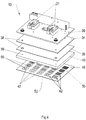
- a further embodiment of the heating device 10, 12 according to the invention is shown.
- the structure of the heating device 10, 12 is the structure of the heater 10, 12 in Fig. 3 similar. It differs in that the recesses 42 are formed in the removable plate 48 instead of in the heating plate 40.
- the removable plate 48 in Fig. 4 in turn has the working surface 52 and a heating plate 40 facing side 50, wherein on the heating plate 40 facing side 50, the recesses 42 are formed.
- at least one subunit of the carrier mounting unit 31 is shown, which is fixedly connected to the carrier plate 26 on the carrier surface 30.
- Fig. 3 is the plurality of recesses 42 which are formed in the heating plate 40, covered by the removable plate 48 and in Fig. 4
- the plurality of recesses 42 which are formed in the removable plate 48, covered by the heating plate 40.
- a plurality of cavities 60 are formed between the heating plate 40 and the removable plate 48.
- the plurality of cavities 60 is preferably filled with air.
- both the heating plate 40 and the removable plate 48 have recesses 42 at the same time.
- the recesses 42 in the heating plate 40 and in the removable plate 48 may be identical, so that, for example, the recess 42 in the heating plate 40 are covered by the recesses 42 in the removable plate 48.
- Fig. 3 and 4 exemplified recesses 42 in the heating plate 40 or the removable plate 48 are in Fig. 5 once more clearly shown.
- Fig. 5 illustrated embodiment of the heater substantially corresponds to the embodiment of Fig. 3 , but here the heating plate 40 simultaneously assumes the function of a support plate. An independent support plate is therefore no longer available.
- a plan view of a plurality of different patterns of the recesses 42 is shown by way of example in the heating plate 40.
- the same patterns, which are shown here on the heating plate 40 may also be present on the removable plate 48.
- normally all recesses 42 of a heating plate 40 and a removable plate 48 have the same pattern and this is formed over the entire surface of the respective plate.
- the illustration is only a simple overview of possible patterns and configurations of individual recesses.
- the recesses 42 are in Fig. 6 and Fig. 7 formed in a predetermined pattern on the heating plate 40 or the removable plate 48.
- the predetermined pattern may have any shape.
- the recesses 42 are distributed in a regular pattern on the heating plate 40 or the removable plate 48.
- the recesses 42 are distributed in rows and columns on the heating plate 40 or the removable plate 48. Between the individual rows and columns, the heating plate 40 in Fig. 6 and 7 the recesses 44 into which the permanent magnets 46 are inserted, as already described above.
- the recesses 42 are each formed in the heating plate 40 or removable plate 48 as sinks.
- the depth of the recesses 42 may vary depending on the requirements conditions.
- the depth of the recesses 42 is dependent on the desired temperature gradient or temperature profile.
- the working surface 52 of the removable plate 48 has a lower temperature than in the recessless areas.
- the temperature can be up to about 60% lower than in the recessless areas.
- the recesses 42 may have a depth of between 0.05 mm and 1.00 mm, preferably between 0.10 mm and 0.50 mm.
- a single or multiple elevations 56 may be formed.
- the elevations 56 extend from a bottom 58 of the respective recess 42.
- the height of the elevations 56 may also vary depending on the requirement profile.
- the survey 56 for example, equal to the depth of the recess 42nd be or have a lower level. However, the height of the protrusion 56 can not be greater than the depth of the recess 42.
- the configuration of the recesses 42 may be different. There are all possible forms conceivable.
Landscapes
- Engineering & Computer Science (AREA)
- Mechanical Engineering (AREA)
- Blow-Moulding Or Thermoforming Of Plastics Or The Like (AREA)
Claims (15)
- Dispositif de chauffage (10, 12) destiné à chauffer une feuille, pourvu
d'une plaque chauffante (40), et
d'une plaque interchangeable (48), qui est reliée à la plaque chauffante (40),
dans lequel
au moins une parmi la plaque chauffante (40) et la plaque interchangeable (48) présente un creux (42) ou une pluralité de creux (42), et
la plaque chauffante (40) et la plaque interchangeable (48) sont reliées l'une à l'autre de telle sorte que le creux (42) ou la pluralité de creux (42) sont recouverts par l'autre parmi la plaque chauffante (40) et la plaque interchangeable (48), de sorte qu'une cavité (60) ou une pluralité de cavités (60) sont formées entre la plaque chauffante (40) et la plaque interchangeable (48),
caractérisé en ce que chaque cavité (60) est remplie d'air. - Dispositif de chauffage (10, 12) selon la revendication 1, caractérisé en ce que la plaque chauffante (40) présente des évidements (44), dans lesquels des aimants permanents (46) sont logés, qui relient la plaque interchangeable (48) de façon magnétique à la plaque chauffante (40).
- Dispositif de chauffage (10, 12) selon la revendication 1 ou 2, caractérisé en ce que la plaque interchangeable (48) est revêtue sur la face tournée vers la plaque chauffante (40) d'un matériau pouvant subir une attraction magnétique.
- Dispositif de chauffage (10, 12) selon l'une quelconque des revendications précédentes, caractérisé en ce que chaque creux (42) est formé dans la plaque chauffante (40) et est recouvert par la plaque interchangeable (48).
- Dispositif de chauffage (10, 12) selon l'une quelconque des revendications 1 à 4, caractérisé en ce que chaque creux (42) est formé dans la plaque interchangeable (48) et est recouvert par la plaque chauffante (40).
- Dispositif de chauffage (10, 12) selon l'une quelconque des revendications précédentes, caractérisé en ce que les creux (42) sont répartis suivant un motif prédéfini sur la plaque chauffante (40) ou la plaque interchangeable (48).
- Dispositif de chauffage (10, 12) selon la revendication 6, caractérisé en ce que les creux (42) sont répartis suivant un motif régulier sur la plaque chauffante (40) ou la plaque interchangeable (48).
- Dispositif de chauffage (10, 12) selon l'une quelconque des revendications précédentes, caractérisé en ce que les creux (42) sont agencés en lignes et en colonnes sur la plaque chauffante ou la plaque interchangeable (48).
- Dispositif de chauffage (10, 12) selon l'une quelconque des revendications précédentes, caractérisé en ce que des élévations (56), qui s'étendent à partir d'un fond (58) des creux (42), sont formées dans les creux (42).
- Dispositif de chauffage (10, 12) selon l'une quelconque des revendications précédentes, caractérisé en ce que les creux (42) présentent une profondeur comprise entre 0,05 mm et 1,00 mm, de préférence entre 0,10 mm et 0,50 mm.
- Dispositif de chauffage (10, 12) selon l'une quelconque des revendications précédentes, caractérisé en ce qu'il présente en outre une plaque de support (26), qui est reliée à la plaque chauffante (40), dans lequel la plaque chauffante (40) est agencée entre la plaque de support (26) et la plaque interchangeable (48) .
- Dispositif de chauffage (10, 12) selon la revendication 11, caractérisé en ce qu'un élément isolant (34) est agencé entre la plaque de support (26) et la plaque chauffante (40).
- Dispositif de chauffage (10, 12) selon la revendication 11 ou 12, caractérisé en ce qu'un mat chauffant (36) est agencé entre la plaque de support (26) et la plaque chauffante (40)
- Unité de chauffage (4) pourvue d'au moins deux dispositifs de chauffage (10, 12), qui sont agencés à l'opposé l'un de l'autre et parmi lesquels au moins l'un peut être déplacé par rapport à l'autre, dans laquelle au moins un dispositif de chauffage (10, 12) selon l'une quelconque des revendications précédentes est réalisé.
- Machine de thermoformage (2) destinée au formage d'alvéoles dans une feuille pour la production d'une bande alvéolée, pourvue d'au moins un dispositif de chauffage (10, 12) destiné à chauffer la feuille selon l'une quelconque des revendications 1 à 13 ou d'une unité de chauffage (4) selon la revendication 14.
Priority Applications (1)
| Application Number | Priority Date | Filing Date | Title |
|---|---|---|---|
| EP16152933.4A EP3078478B1 (fr) | 2015-04-09 | 2016-01-27 | Dispositif de chauffage destine au rechauffement d'une feuille |
Applications Claiming Priority (2)
| Application Number | Priority Date | Filing Date | Title |
|---|---|---|---|
| EP15162889 | 2015-04-09 | ||
| EP16152933.4A EP3078478B1 (fr) | 2015-04-09 | 2016-01-27 | Dispositif de chauffage destine au rechauffement d'une feuille |
Publications (2)
| Publication Number | Publication Date |
|---|---|
| EP3078478A1 EP3078478A1 (fr) | 2016-10-12 |
| EP3078478B1 true EP3078478B1 (fr) | 2019-08-28 |
Family
ID=52997846
Family Applications (1)
| Application Number | Title | Priority Date | Filing Date |
|---|---|---|---|
| EP16152933.4A Active EP3078478B1 (fr) | 2015-04-09 | 2016-01-27 | Dispositif de chauffage destine au rechauffement d'une feuille |
Country Status (2)
| Country | Link |
|---|---|
| EP (1) | EP3078478B1 (fr) |
| ES (1) | ES2751657T3 (fr) |
Cited By (5)
| Publication number | Priority date | Publication date | Assignee | Title |
|---|---|---|---|---|
| WO2022002968A3 (fr) * | 2020-07-01 | 2022-03-17 | Gea Food Solutions Germany Gmbh | Outil de scellage doté d'un moyen de chauffage |
| EP4257336A1 (fr) * | 2022-04-04 | 2023-10-11 | Henkel AG & Co. KGaA | Portions unitaires de détergent |
| EP4257335A1 (fr) * | 2022-04-04 | 2023-10-11 | Henkel AG & Co. KGaA | Procédé de fabrication de portions unitaires de détergent |
| EP4257334A1 (fr) * | 2022-04-04 | 2023-10-11 | Henkel AG & Co. KGaA | Dispositif de chauffage |
| EP4368368A1 (fr) * | 2022-11-10 | 2024-05-15 | Harro Höfliger Verpackungsmaschinen GmbH | Dispositif d'emboutissage profond, machine d'emballage dotée d'un dispositif d'emboutissage profond et procédé de fonctionnement du dispositif d'emboutissage profond |
Family Cites Families (4)
| Publication number | Priority date | Publication date | Assignee | Title |
|---|---|---|---|---|
| US3386503A (en) * | 1966-02-24 | 1968-06-04 | Continental Can Co | Differential heating plate |
| JPH0694161B2 (ja) | 1989-12-28 | 1994-11-24 | 出光石油化学株式会社 | 熱可塑性樹脂シートの熱成形方法及び装置 |
| US20120131730A1 (en) * | 2007-08-10 | 2012-05-31 | Gilad Shoham | Contoured Face Shields and Method of Producing Optically Clear Parts |
| EP2390084B1 (fr) | 2010-05-26 | 2012-07-18 | UHLMANN PAC-SYSTEME GmbH & Co. KG | Plaque chauffante destinée au réchauffement d'une feuille |
-
2016
- 2016-01-27 ES ES16152933T patent/ES2751657T3/es active Active
- 2016-01-27 EP EP16152933.4A patent/EP3078478B1/fr active Active
Non-Patent Citations (1)
| Title |
|---|
| None * |
Cited By (9)
| Publication number | Priority date | Publication date | Assignee | Title |
|---|---|---|---|---|
| WO2022002968A3 (fr) * | 2020-07-01 | 2022-03-17 | Gea Food Solutions Germany Gmbh | Outil de scellage doté d'un moyen de chauffage |
| EP4420991A3 (fr) * | 2020-07-01 | 2024-09-04 | Gea Food Solutions Germany GmbH | Outil de scellage avec un moyen de chauffage |
| EP4257336A1 (fr) * | 2022-04-04 | 2023-10-11 | Henkel AG & Co. KGaA | Portions unitaires de détergent |
| EP4257335A1 (fr) * | 2022-04-04 | 2023-10-11 | Henkel AG & Co. KGaA | Procédé de fabrication de portions unitaires de détergent |
| EP4257334A1 (fr) * | 2022-04-04 | 2023-10-11 | Henkel AG & Co. KGaA | Dispositif de chauffage |
| WO2023193965A1 (fr) * | 2022-04-04 | 2023-10-12 | Henkel Ag & Co. Kgaa | Procédé de fabrication d'une portion unitaire de détergent |
| WO2023193964A1 (fr) * | 2022-04-04 | 2023-10-12 | Henkel Ag & Co. Kgaa | Dispositif de chauffage pour produire des unités de dosage de détergent présentant des propriétés améliorées |
| WO2023193966A1 (fr) * | 2022-04-04 | 2023-10-12 | Henkel Ag & Co. Kgaa | Portions unitaires de détergent |
| EP4368368A1 (fr) * | 2022-11-10 | 2024-05-15 | Harro Höfliger Verpackungsmaschinen GmbH | Dispositif d'emboutissage profond, machine d'emballage dotée d'un dispositif d'emboutissage profond et procédé de fonctionnement du dispositif d'emboutissage profond |
Also Published As
| Publication number | Publication date |
|---|---|
| EP3078478A1 (fr) | 2016-10-12 |
| ES2751657T3 (es) | 2020-04-01 |
Similar Documents
| Publication | Publication Date | Title |
|---|---|---|
| EP3078478A1 (fr) | Dispositif de chauffage destine au rechauffement d'une feuille | |
| EP1426110B1 (fr) | Bloc de régulation de température doté de dispositifs de régulation de température et procédé d'utilisation | |
| EP0936945B1 (fr) | Bloc de regulation de temperature dote de logements | |
| DE3505256C2 (de) | Vorrichtung zum berührungsfreien Führen von Warenbahnen, insbesondere Metallbändern, mittels eines Gasmediums | |
| EP4105006B1 (fr) | Dispositif pour le traitement par pression de matériaux plats | |
| WO2016192994A1 (fr) | Procédé de trempe homogène sans contact de surfaces à tremper non continues et dispositif à cet effet | |
| CH623777A5 (fr) | ||
| DE10201830A1 (de) | Düsenende für eine Spritzgussdüse mit mehreren Spitzen | |
| EP3487650B1 (fr) | Plaque de lingotière et lingotière | |
| DE2535989B2 (de) | Vorrichtung zum Aushärten stranggepreBter Körper | |
| DE102004005703B4 (de) | Verfahren und Apparatur zur kontinuierlichen Formung eines Streifens aus Kunststoff mit einem gewellten Profil | |
| DE102015012844A1 (de) | Verfahren und Vorrichtung zur generativen Herstellung eines dreidimensionalen Formkörpers aus einem formlosen Material mittels Laserstrahlschmelzens, sowie Kammervorrichtung für das Verfahren und die Vorrichtung | |
| EP1786737B1 (fr) | Section de refroidissement de verre mousse | |
| EP3181528B1 (fr) | Chaine de transport de recipients en verre a travers un four comprenant des supports conçus comme des maillons et dispositif de transport dote d'une telle chaine de transport | |
| DE60033667T2 (de) | Nicht rotierendes, zylindrisches luftpolster zur erzeugung einer bandschwebung und verfahren zum stützen und führen eines endlosen flexiblen giessbandes | |
| DE60201862T2 (de) | Thermoformwerkzeug zum formen von Kunststofffolie | |
| DE112005001013T5 (de) | Formverteiler mit geringem Abstand | |
| DE102019113695B4 (de) | Konturplatte zum Aufbringen von Heißgas entlang einer Schweißlinie eines Kunststoffteils, Verfahren zum Herstellen einer Konturplatte und eine Vorrichtung zum Schweißen von Kunststoffteilen | |
| DE4230015C2 (de) | Plattenelement für eine Etagen-Plattenpresse | |
| DE102016108467B3 (de) | Werkzeugvorrichtung | |
| EP4177030A1 (fr) | Poste de travail pour machine d'emballage de traitement de film | |
| DE4212335C2 (de) | Extrusionsvorrichtung zur Herstellung von Platten | |
| EP3118128B1 (fr) | Dispositif de retractation | |
| DE102017127657B3 (de) | Werkzeug für eine Vorrichtung zum wärmegestützten Umformen, insbesondere Warmumformen und/oder Presshärten sowie Vorrichtung und Verfahren zum wärmegestützten Umformen, insbesondere Warmumformen und/oder Presshärten mit wenigstens einem solchen Werkzeug | |
| DE2218557C3 (de) | Vorrichtung zum Herstellen von Wandelementen |
Legal Events
| Date | Code | Title | Description |
|---|---|---|---|
| PUAI | Public reference made under article 153(3) epc to a published international application that has entered the european phase |
Free format text: ORIGINAL CODE: 0009012 |
|
| AK | Designated contracting states |
Kind code of ref document: A1 Designated state(s): AL AT BE BG CH CY CZ DE DK EE ES FI FR GB GR HR HU IE IS IT LI LT LU LV MC MK MT NL NO PL PT RO RS SE SI SK SM TR |
|
| AX | Request for extension of the european patent |
Extension state: BA ME |
|
| STAA | Information on the status of an ep patent application or granted ep patent |
Free format text: STATUS: REQUEST FOR EXAMINATION WAS MADE |
|
| 17P | Request for examination filed |
Effective date: 20170410 |
|
| RBV | Designated contracting states (corrected) |
Designated state(s): AL AT BE BG CH CY CZ DE DK EE ES FI FR GB GR HR HU IE IS IT LI LT LU LV MC MK MT NL NO PL PT RO RS SE SI SK SM TR |
|
| GRAP | Despatch of communication of intention to grant a patent |
Free format text: ORIGINAL CODE: EPIDOSNIGR1 |
|
| STAA | Information on the status of an ep patent application or granted ep patent |
Free format text: STATUS: GRANT OF PATENT IS INTENDED |
|
| INTG | Intention to grant announced |
Effective date: 20190603 |
|
| GRAS | Grant fee paid |
Free format text: ORIGINAL CODE: EPIDOSNIGR3 |
|
| GRAA | (expected) grant |
Free format text: ORIGINAL CODE: 0009210 |
|
| STAA | Information on the status of an ep patent application or granted ep patent |
Free format text: STATUS: THE PATENT HAS BEEN GRANTED |
|
| AK | Designated contracting states |
Kind code of ref document: B1 Designated state(s): AL AT BE BG CH CY CZ DE DK EE ES FI FR GB GR HR HU IE IS IT LI LT LU LV MC MK MT NL NO PL PT RO RS SE SI SK SM TR |
|
| REG | Reference to a national code |
Ref country code: GB Ref legal event code: FG4D Free format text: NOT ENGLISH |
|
| REG | Reference to a national code |
Ref country code: CH Ref legal event code: EP |
|
| REG | Reference to a national code |
Ref country code: DE Ref legal event code: R096 Ref document number: 502016006258 Country of ref document: DE |
|
| REG | Reference to a national code |
Ref country code: AT Ref legal event code: REF Ref document number: 1171865 Country of ref document: AT Kind code of ref document: T Effective date: 20190915 |
|
| REG | Reference to a national code |
Ref country code: IE Ref legal event code: FG4D Free format text: LANGUAGE OF EP DOCUMENT: GERMAN |
|
| REG | Reference to a national code |
Ref country code: NL Ref legal event code: MP Effective date: 20190828 |
|
| REG | Reference to a national code |
Ref country code: LT Ref legal event code: MG4D |
|
| PG25 | Lapsed in a contracting state [announced via postgrant information from national office to epo] |
Ref country code: FI Free format text: LAPSE BECAUSE OF FAILURE TO SUBMIT A TRANSLATION OF THE DESCRIPTION OR TO PAY THE FEE WITHIN THE PRESCRIBED TIME-LIMIT Effective date: 20190828 Ref country code: HR Free format text: LAPSE BECAUSE OF FAILURE TO SUBMIT A TRANSLATION OF THE DESCRIPTION OR TO PAY THE FEE WITHIN THE PRESCRIBED TIME-LIMIT Effective date: 20190828 Ref country code: BG Free format text: LAPSE BECAUSE OF FAILURE TO SUBMIT A TRANSLATION OF THE DESCRIPTION OR TO PAY THE FEE WITHIN THE PRESCRIBED TIME-LIMIT Effective date: 20191128 Ref country code: SE Free format text: LAPSE BECAUSE OF FAILURE TO SUBMIT A TRANSLATION OF THE DESCRIPTION OR TO PAY THE FEE WITHIN THE PRESCRIBED TIME-LIMIT Effective date: 20190828 Ref country code: NO Free format text: LAPSE BECAUSE OF FAILURE TO SUBMIT A TRANSLATION OF THE DESCRIPTION OR TO PAY THE FEE WITHIN THE PRESCRIBED TIME-LIMIT Effective date: 20191128 Ref country code: LT Free format text: LAPSE BECAUSE OF FAILURE TO SUBMIT A TRANSLATION OF THE DESCRIPTION OR TO PAY THE FEE WITHIN THE PRESCRIBED TIME-LIMIT Effective date: 20190828 Ref country code: NL Free format text: LAPSE BECAUSE OF FAILURE TO SUBMIT A TRANSLATION OF THE DESCRIPTION OR TO PAY THE FEE WITHIN THE PRESCRIBED TIME-LIMIT Effective date: 20190828 Ref country code: PT Free format text: LAPSE BECAUSE OF FAILURE TO SUBMIT A TRANSLATION OF THE DESCRIPTION OR TO PAY THE FEE WITHIN THE PRESCRIBED TIME-LIMIT Effective date: 20191230 |
|
| PG25 | Lapsed in a contracting state [announced via postgrant information from national office to epo] |
Ref country code: GR Free format text: LAPSE BECAUSE OF FAILURE TO SUBMIT A TRANSLATION OF THE DESCRIPTION OR TO PAY THE FEE WITHIN THE PRESCRIBED TIME-LIMIT Effective date: 20191129 Ref country code: LV Free format text: LAPSE BECAUSE OF FAILURE TO SUBMIT A TRANSLATION OF THE DESCRIPTION OR TO PAY THE FEE WITHIN THE PRESCRIBED TIME-LIMIT Effective date: 20190828 Ref country code: AL Free format text: LAPSE BECAUSE OF FAILURE TO SUBMIT A TRANSLATION OF THE DESCRIPTION OR TO PAY THE FEE WITHIN THE PRESCRIBED TIME-LIMIT Effective date: 20190828 Ref country code: IS Free format text: LAPSE BECAUSE OF FAILURE TO SUBMIT A TRANSLATION OF THE DESCRIPTION OR TO PAY THE FEE WITHIN THE PRESCRIBED TIME-LIMIT Effective date: 20191228 Ref country code: RS Free format text: LAPSE BECAUSE OF FAILURE TO SUBMIT A TRANSLATION OF THE DESCRIPTION OR TO PAY THE FEE WITHIN THE PRESCRIBED TIME-LIMIT Effective date: 20190828 |
|
| PG25 | Lapsed in a contracting state [announced via postgrant information from national office to epo] |
Ref country code: TR Free format text: LAPSE BECAUSE OF FAILURE TO SUBMIT A TRANSLATION OF THE DESCRIPTION OR TO PAY THE FEE WITHIN THE PRESCRIBED TIME-LIMIT Effective date: 20190828 |
|
| REG | Reference to a national code |
Ref country code: ES Ref legal event code: FG2A Ref document number: 2751657 Country of ref document: ES Kind code of ref document: T3 Effective date: 20200401 |
|
| PG25 | Lapsed in a contracting state [announced via postgrant information from national office to epo] |
Ref country code: EE Free format text: LAPSE BECAUSE OF FAILURE TO SUBMIT A TRANSLATION OF THE DESCRIPTION OR TO PAY THE FEE WITHIN THE PRESCRIBED TIME-LIMIT Effective date: 20190828 Ref country code: PL Free format text: LAPSE BECAUSE OF FAILURE TO SUBMIT A TRANSLATION OF THE DESCRIPTION OR TO PAY THE FEE WITHIN THE PRESCRIBED TIME-LIMIT Effective date: 20190828 Ref country code: RO Free format text: LAPSE BECAUSE OF FAILURE TO SUBMIT A TRANSLATION OF THE DESCRIPTION OR TO PAY THE FEE WITHIN THE PRESCRIBED TIME-LIMIT Effective date: 20190828 Ref country code: DK Free format text: LAPSE BECAUSE OF FAILURE TO SUBMIT A TRANSLATION OF THE DESCRIPTION OR TO PAY THE FEE WITHIN THE PRESCRIBED TIME-LIMIT Effective date: 20190828 |
|
| PG25 | Lapsed in a contracting state [announced via postgrant information from national office to epo] |
Ref country code: SK Free format text: LAPSE BECAUSE OF FAILURE TO SUBMIT A TRANSLATION OF THE DESCRIPTION OR TO PAY THE FEE WITHIN THE PRESCRIBED TIME-LIMIT Effective date: 20190828 Ref country code: SM Free format text: LAPSE BECAUSE OF FAILURE TO SUBMIT A TRANSLATION OF THE DESCRIPTION OR TO PAY THE FEE WITHIN THE PRESCRIBED TIME-LIMIT Effective date: 20190828 Ref country code: IS Free format text: LAPSE BECAUSE OF FAILURE TO SUBMIT A TRANSLATION OF THE DESCRIPTION OR TO PAY THE FEE WITHIN THE PRESCRIBED TIME-LIMIT Effective date: 20200224 Ref country code: CZ Free format text: LAPSE BECAUSE OF FAILURE TO SUBMIT A TRANSLATION OF THE DESCRIPTION OR TO PAY THE FEE WITHIN THE PRESCRIBED TIME-LIMIT Effective date: 20190828 |
|
| REG | Reference to a national code |
Ref country code: DE Ref legal event code: R097 Ref document number: 502016006258 Country of ref document: DE |
|
| PLBE | No opposition filed within time limit |
Free format text: ORIGINAL CODE: 0009261 |
|
| STAA | Information on the status of an ep patent application or granted ep patent |
Free format text: STATUS: NO OPPOSITION FILED WITHIN TIME LIMIT |
|
| PG2D | Information on lapse in contracting state deleted |
Ref country code: IS |
|
| 26N | No opposition filed |
Effective date: 20200603 |
|
| PG25 | Lapsed in a contracting state [announced via postgrant information from national office to epo] |
Ref country code: MC Free format text: LAPSE BECAUSE OF FAILURE TO SUBMIT A TRANSLATION OF THE DESCRIPTION OR TO PAY THE FEE WITHIN THE PRESCRIBED TIME-LIMIT Effective date: 20190828 Ref country code: SI Free format text: LAPSE BECAUSE OF FAILURE TO SUBMIT A TRANSLATION OF THE DESCRIPTION OR TO PAY THE FEE WITHIN THE PRESCRIBED TIME-LIMIT Effective date: 20190828 |
|
| REG | Reference to a national code |
Ref country code: CH Ref legal event code: PL |
|
| GBPC | Gb: european patent ceased through non-payment of renewal fee |
Effective date: 20200127 |
|
| REG | Reference to a national code |
Ref country code: BE Ref legal event code: MM Effective date: 20200131 |
|
| PG25 | Lapsed in a contracting state [announced via postgrant information from national office to epo] |
Ref country code: GB Free format text: LAPSE BECAUSE OF NON-PAYMENT OF DUE FEES Effective date: 20200127 Ref country code: FR Free format text: LAPSE BECAUSE OF NON-PAYMENT OF DUE FEES Effective date: 20200131 Ref country code: LU Free format text: LAPSE BECAUSE OF NON-PAYMENT OF DUE FEES Effective date: 20200127 |
|
| PG25 | Lapsed in a contracting state [announced via postgrant information from national office to epo] |
Ref country code: CH Free format text: LAPSE BECAUSE OF NON-PAYMENT OF DUE FEES Effective date: 20200131 Ref country code: BE Free format text: LAPSE BECAUSE OF NON-PAYMENT OF DUE FEES Effective date: 20200131 Ref country code: LI Free format text: LAPSE BECAUSE OF NON-PAYMENT OF DUE FEES Effective date: 20200131 |
|
| PG25 | Lapsed in a contracting state [announced via postgrant information from national office to epo] |
Ref country code: IE Free format text: LAPSE BECAUSE OF NON-PAYMENT OF DUE FEES Effective date: 20200127 |
|
| REG | Reference to a national code |
Ref country code: AT Ref legal event code: MM01 Ref document number: 1171865 Country of ref document: AT Kind code of ref document: T Effective date: 20210127 |
|
| PG25 | Lapsed in a contracting state [announced via postgrant information from national office to epo] |
Ref country code: AT Free format text: LAPSE BECAUSE OF NON-PAYMENT OF DUE FEES Effective date: 20210127 |
|
| PG25 | Lapsed in a contracting state [announced via postgrant information from national office to epo] |
Ref country code: MT Free format text: LAPSE BECAUSE OF FAILURE TO SUBMIT A TRANSLATION OF THE DESCRIPTION OR TO PAY THE FEE WITHIN THE PRESCRIBED TIME-LIMIT Effective date: 20190828 Ref country code: CY Free format text: LAPSE BECAUSE OF FAILURE TO SUBMIT A TRANSLATION OF THE DESCRIPTION OR TO PAY THE FEE WITHIN THE PRESCRIBED TIME-LIMIT Effective date: 20190828 |
|
| PG25 | Lapsed in a contracting state [announced via postgrant information from national office to epo] |
Ref country code: MK Free format text: LAPSE BECAUSE OF FAILURE TO SUBMIT A TRANSLATION OF THE DESCRIPTION OR TO PAY THE FEE WITHIN THE PRESCRIBED TIME-LIMIT Effective date: 20190828 |
|
| PGFP | Annual fee paid to national office [announced via postgrant information from national office to epo] |
Ref country code: ES Payment date: 20260202 Year of fee payment: 11 |
|
| PGFP | Annual fee paid to national office [announced via postgrant information from national office to epo] |
Ref country code: DE Payment date: 20260128 Year of fee payment: 11 |
|
| PGFP | Annual fee paid to national office [announced via postgrant information from national office to epo] |
Ref country code: IT Payment date: 20260128 Year of fee payment: 11 |