EP3078495A1 - Presse rotative - Google Patents
Presse rotative Download PDFInfo
- Publication number
- EP3078495A1 EP3078495A1 EP16163099.1A EP16163099A EP3078495A1 EP 3078495 A1 EP3078495 A1 EP 3078495A1 EP 16163099 A EP16163099 A EP 16163099A EP 3078495 A1 EP3078495 A1 EP 3078495A1
- Authority
- EP
- European Patent Office
- Prior art keywords
- web
- printing
- printing machine
- color
- correction
- Prior art date
- Legal status (The legal status is an assumption and is not a legal conclusion. Google has not performed a legal analysis and makes no representation as to the accuracy of the status listed.)
- Withdrawn
Links
- 238000012937 correction Methods 0.000 claims abstract description 60
- 239000000203 mixture Substances 0.000 claims abstract description 30
- 238000002156 mixing Methods 0.000 claims abstract description 15
- 238000005259 measurement Methods 0.000 claims abstract description 11
- 238000011179 visual inspection Methods 0.000 claims abstract description 3
- 238000012360 testing method Methods 0.000 claims description 5
- 238000002360 preparation method Methods 0.000 claims description 4
- 239000000758 substrate Substances 0.000 claims description 3
- 239000000976 ink Substances 0.000 description 49
- 239000003086 colorant Substances 0.000 description 16
- 239000003973 paint Substances 0.000 description 9
- 238000007774 anilox coating Methods 0.000 description 7
- 238000004519 manufacturing process Methods 0.000 description 5
- 239000000463 material Substances 0.000 description 5
- 230000008901 benefit Effects 0.000 description 4
- 238000001035 drying Methods 0.000 description 4
- 238000000034 method Methods 0.000 description 4
- 238000007689 inspection Methods 0.000 description 3
- 238000001228 spectrum Methods 0.000 description 3
- 230000007423 decrease Effects 0.000 description 2
- 230000003247 decreasing effect Effects 0.000 description 2
- 238000011156 evaluation Methods 0.000 description 2
- 238000011049 filling Methods 0.000 description 2
- 230000010354 integration Effects 0.000 description 2
- 239000007788 liquid Substances 0.000 description 2
- 230000002093 peripheral effect Effects 0.000 description 2
- 239000002904 solvent Substances 0.000 description 2
- 241001295925 Gegenes Species 0.000 description 1
- 208000027418 Wounds and injury Diseases 0.000 description 1
- 230000001133 acceleration Effects 0.000 description 1
- 238000009825 accumulation Methods 0.000 description 1
- 239000000853 adhesive Substances 0.000 description 1
- 230000006378 damage Effects 0.000 description 1
- 230000001419 dependent effect Effects 0.000 description 1
- 238000011161 development Methods 0.000 description 1
- 230000018109 developmental process Effects 0.000 description 1
- 230000000694 effects Effects 0.000 description 1
- 208000014674 injury Diseases 0.000 description 1
- 230000005693 optoelectronics Effects 0.000 description 1
- 238000003825 pressing Methods 0.000 description 1
- 230000003595 spectral effect Effects 0.000 description 1
- 238000003756 stirring Methods 0.000 description 1
- 238000012876 topography Methods 0.000 description 1
- 238000012546 transfer Methods 0.000 description 1
- 230000000007 visual effect Effects 0.000 description 1
- 239000002699 waste material Substances 0.000 description 1
- 238000004804 winding Methods 0.000 description 1
Images


Classifications
-
- B—PERFORMING OPERATIONS; TRANSPORTING
- B41—PRINTING; LINING MACHINES; TYPEWRITERS; STAMPS
- B41F—PRINTING MACHINES OR PRESSES
- B41F31/00—Inking arrangements or devices
- B41F31/02—Ducts, containers, supply or metering devices
-
- B—PERFORMING OPERATIONS; TRANSPORTING
- B41—PRINTING; LINING MACHINES; TYPEWRITERS; STAMPS
- B41F—PRINTING MACHINES OR PRESSES
- B41F33/00—Indicating, counting, warning, control or safety devices
- B41F33/0009—Central control units
-
- B—PERFORMING OPERATIONS; TRANSPORTING
- B41—PRINTING; LINING MACHINES; TYPEWRITERS; STAMPS
- B41F—PRINTING MACHINES OR PRESSES
- B41F33/00—Indicating, counting, warning, control or safety devices
- B41F33/04—Tripping devices or stop-motions
- B41F33/10—Tripping devices or stop-motions for starting or stopping operation of damping or inking units
Definitions
- the invention relates to a rotary printing machine.
- the quality of the printing result obtained depends on various printing parameters, which relate to the setting of the printing press, for example, the pressure of the printing cylinder against the web, and the properties of the printing inks used, for example, their viscosity and - in mixed colors such as so-called spot colors - the mixing ratio of the colors. It often proves necessary to correct the parameters after initial print results. It is therefore expedient to carry out a test print before the start of an actual printing run in order to obtain a printed pattern which can then be evaluated and measured with regard to its quality and in particular with regard to the color impression and forms the basis for determining the required corrections.
- the object of the invention is to provide a printing machine that facilitates the determination and making the necessary corrections.
- a light table and a color correction workstation in that at the light table are installed a standardized light source for the visual inspection of a printed pattern separated from the web, and a screen and a colorimeter, both connected to a computer, on the software for evaluating the measurement results of the colorimeter and for display of these measurement results is installed on the screen and that at the color correction workstation ink containers for the printing machine to be supplied ink and a balance for preparing correction color mixtures with predetermined mixing ratios are installed.
- the invention has the advantage that the evaluation of the printing pattern and the preparation of color correction mixtures can be made directly on the spot on the printing press, so that the staff need not travel long distances. Another advantage is that the printing machine can also be used in an environment in which there is no special infrastructure with light tables and color kitchens for determining and executing the necessary corrections.
- On the computer which is preferably networked with the control of the printing press, can run a correction software (see, eg DE 10 2007 032 944 B4 ), which automatically calculates the necessary corrections for the printing parameters based on the color measurement results.
- the print parameters and the associated color values measured on the print pattern as well as the corresponding desired color values can then be stored electronically, so that they are available again for comparable print jobs at any time.
- On the computer can also run a known software, with the help of the results obtained with the color measuring device, the necessary corrective mixtures for spot colors as well as the instructions for making these correction mixtures.
- test print routine ensures that the print pattern is produced under conditions that are comparable to the conditions in a later actual print run, in particular at a web speed that is comparable to the web speed used later in the actual print run.
- the automatic path recording and automatic rewinding allow the web to rewind automatically to the point where the desired print pattern produced at the correct speed on the outer peripheral surface of the reel on the rewinder or on a straight line of the reel Recoiler deducted section of the web is visible and accessible, so that then the inspection and, where appropriate, the necessary color measurements and can be made.
- the invention thus enables the production of a printing pattern with less personnel and labor and at the same time with improved accuracy and lower accident risk.
- the invention therefore also has the advantage that the material consumption necessary for producing the printing pattern is kept to a minimum. This not only affects the consumption of substrate and thus the accumulation of waste, but also the consumption of printing ink. This latter aspect is particularly important when spot colors need to be corrected for the premixed ink composition.
- the correction is usually achieved by preparing a correction mixture in which the quantitative ratio of the individual colors is chosen such that the desired corrected mixing ratio results if the correction mixture is added to the ink already present in the ink system of the printing press.
- the consumption of ink is so low that it can be neglected in the calculation of the correction. It is thus sufficient to determine or measure the amount of ink that is filled in the initial filling of the printing machine before the trial print run in the color system, and a subsequent consumption measurement is not required.
- the invention is particularly advantageous in printing presses which have a so-called SmartGPS system, as described for example in the European patent EP 1 916 102 B1 the applicant is described.
- This system makes it possible to calculate the settings of the other printing parameters, in particular the pressure of the printing cylinders against the web, even before the beginning of the printing run or the trial printing run in such a way, that after the start of the printing machine hardly any subsequent corrections are required.
- This makes it possible to extremely shorten the start-up phase of the printing press, in which the printing parameters still need to be fine-tuned, so that correspondingly the material consumption for the production of the printing pattern can be kept very small.
- the fine adjustments to the print parameters are made while the press is starting up at a reduced speed.
- the web used up to completion of these adjustments will then usually have a length of less than 20 m, and correspondingly small is the consumption of ink in the start-up phase before the web speed is increased to the desired speed for the production of the printing pattern.
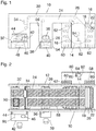
- FIG. 1 As an example of a rotary printing machine, a central cylinder flexographic printing machine is shown.
- Fig. 2 shows the same machine in plan view.
- a central cylinder 14 is mounted, on whose circumference several inking units 16, in the example shown eight inking units are arranged, for example for four process colors yellow, magenta, cyan and black, and for four premixed spot colors , As usual, each inking unit has a printing cylinder 18, an anilox roller 20 and a chamber doctor blade 22.
- a web 24 of a printing material is withdrawn from an unwinder 26 and guided by means of a train transport system 28 formed by tension and guide rollers to the central cylinder 14 and from there via a drying zone 30 to a rewinder 32.
- the web 24 wraps around the central cylinder 14 over almost its entire circumference, so that it passes through the impression cylinder 18 of all inking units 16.
- the printing cylinders 18 are set against the circumference of the central cylinder 14, and the anilox rollers 20 are attached to the respective printing cylinder so that they transfer liquid ink, which they receive from the chambered doctor blade 22, on the printing cylinder 18, through which the color then transferred to the web 24.
- a multi-color printed image is thus printed on the web 24, which is then dried in the drying zone 30.
- a web inspection camera 34 is arranged, with which selected sections of the printed web can be observed while the printing press is running.
- the images taken by the camera are displayed on a screen 36 in a control station 38 of the printing press, which is arranged on the operating side of the printing press on the side frame 10, for example in the region of the unwinder 26th
- the function of the printing press is controlled by an electronic control system 40, which in Fig. 1 only symbolically in the area of the control station 38 is indicated.
- a light table 42 is installed on the outside, above which a standardized light source 44 is located.
- a printing pattern which was produced in a later described manner with the printing press, can be placed and visually inspected under standardized lighting conditions.
- an opto-electronic colorimeter 46 which is connected to a correction computer 48 and allows the spectrum of selected points on the print pattern to be measured and evaluated electronically. The results of the measurement and / or evaluation can be displayed on a screen 50.
- the side frame 10 forms an access system 52, which allows access to the inking units at standstill of the machine, so that the printing cylinder 18 and the anilox rollers 20 can be replaced if necessary.
- the access system 52 and the unwinder 26 on the one hand and between the unwinder 26 and the winder 32 on the other hand form the two side frames 10, 12 passages 54, 56, which allow the staff to get to the opposite side of the printing press, so the so-called drive side on which the side frame 12 and the drives not shown here for the various rollers and cylinders of the printing press are located.
- a Farbzu investigatedsystems 58 On the drive side and essential components of a Farbzu investigatedsystems 58 are seconded, with which the ink is supplied to the chambered doctor blades 22 of the individual inking units 16 and again fed back from them.
- the chambered doctor blade 22 of each inking unit 16 is associated with a paint container 60 which is placed on a bench 62 on the outside of the side frame 12 and contains the ink for the relevant chamber doctor blade 22.
- FIG Fig. 3 A portion of the ink delivery system 58 - for a single chambered doctor blade 20 - is shown schematically in FIG Fig. 3 shown.
- the ink container 60 is filled to a level 64 with liquid ink, for example, with a premixed spot color.
- a lid 66 which closes the paint container at the top, is penetrated by a suction line 68, with which the ink is pumped via a pump 70 to an inlet of the chamber doctor blade 22.
- the ink is continuously circulated in the ink supply system, and unused ink is returned via a return line 72 in the paint container 60.
- the feed line 68 contains a viscometer 74, with which the viscosity of the ink is constantly monitored. If the viscosity does not correspond to the desired value, solvent is metered in via a valve 76.
- the paint container 60 includes a stirrer 78 which causes the recycled ink and solvent to be mixed with the ink in the container.
- the benches 62 on which the ink containers 60 are placed are integrated into a color correction workstation 80 located on the outside of the side frame 12.
- To this workplace also includes an electronic balance 82, which has a display 84 and is connected by a data line to the correction computer 48.
- the balance 82 is used, on the basis of instructions transmitted by the correction calculator 48 and displayed on the display 84, in a mixing cup 86 (FIG. Fig. 2 and 3 ) to compose a correction mixture which is then input to one of the ink containers 60 in addition to the ink already in the system to correct the composition of the ink.
- the color containers 60 almost completely filled with the desired inks are weighed on the balance 82. It is assumed that the empty weights the ink containers 60 are known or weighed in advance with the balance 82 so that the net weights of each ink in the ink delivery system 58 can be accurately determined. With the help of the pumps 70, the inks are then pumped from the respective paint container 60 into the associated chamber scraper 22, so that the chambered scraper 22 and the supply lines 68 and return lines 72 are filled with ink, whereby the level 64 of the ink in the individual paint containers 60 something decreases.
- a test print routine is now executed in which a print pattern is to be created, by means of which the settings of the various print parameters and the compositions of the spot colors used can then be checked and, if necessary, corrected.
- the machine operator at the control station 38 enters a command "proof print", whereupon the control device 40 automatically controls the printing press so that the test print routine described below is executed.
- the printing cylinder 18 of the individual inking units 16 are employed at the periphery of the central cylinder 14, and the anilox rollers 20 with associated chamber doctor blades 22 are employed at the respective associated printing cylinder.
- the topographies of the printing cylinders 18 and the anilox rollers 22 have been previously measured accurately (as in EP 1 916 102 B1 described), and on the basis of these data, the setting positions for the impression cylinder and anilox rollers are calculated so that the rollers and cylinders touch each other with the appropriate line pressures, so that later minor corrections are needed at best.
- the web transport system 28 is started so that images are printed on the web 24.
- the obtained print images can be viewed with the web-observation camera 34.
- the web speed is initially maintained at a low value until the possibly still necessary corrections to the settings of the printing parameters, in particular the pressure forces, are completed. Typically, these corrections are completed before the first 20 meters of web are printed.
- the web speed is gradually increased, up to a predetermined target value, which preferably corresponds to the web speed used later during the actual printing run.
- the web speed is continuously monitored by the controller 40.
- the controller 40 begins to integrate the speed of the web 24 over time. In this way, the path is calculated which a print pattern printed on the web at the time the desired speed was reached and left the last inking unit 16, travels during the onward transport of the web.
- the web speed is then immediately throttled back and gradually reduced to zero.
- the measurement or integration of the path is continued.
- the print pattern on the web 24 passes through the drying zone 30, passes through the web inspection camera 34, and reaches the rewinder 32 where the web is wound into a reel. Since the web transport has not yet come to a halt at this time, the section of the web containing the print pattern is covered by further web layers.
- the web is stopped, it is rewound by means of the web transport system 28 until the web portion carrying the print pattern is again exposed on the peripheral surface of the reel on the rewinder 32 and withdrawn from the rewinder.
- the required rewinding distance can be calculated by calculating from the integrated way, the print image has taken the lead in total, an offset is subtracted, which corresponds to the length of the path from the last printing unit 16 to the rewinder 32.
- the rewind operation is automatically controlled by the controller 40 and the web is stopped once the print pattern is in the desired position.
- step S1 the printing parameters are set based on the specifications for the individual impression cylinders and anilox rolls.
- step S2 the impression cylinders are turned on the central cylinder and, if necessary, finely adjusted to the first 20 meters.
- step S3 the gradual increase of the web speed begins.
- step S4 it is then checked whether the current web speed V web already corresponds to the target speed V Soll . If this is not the case, the step S4 is repeated until the target speed is reached.
- step S5 the path measurement (integration of the web speed) is started in step S5, and in step S6, the web speed is gradually reduced again.
- step S7 it is checked whether the web speed has decreased to zero. If this is not the case, step S7 is repeated until the web has come to a standstill.
- step S8 the path obtained at this time by integrating the web speed is stored.
- step S9 the impression cylinders are moved away from the central cylinder.
- step S10 the web is automatically rewound by a precalculated path corresponding to that stored in step S8, but reduced by the distance measured between the last inking unit 16 and the rewinder 32 along the path.
- Fig. 2 For example, on the web 24, there are shown a plurality of print images 88 that were printed during the trial print run, but most of them at a web speed that does not match the target speed.
- two benefits are printed with each printing cylinder, so that two printed images 88 lie on the web 24 next to each other. Any one of the two print images 88 that were printed at the time the web was just at the target speed forms the desired print pattern that is in Fig. 2 is designated by 90 and is marked by a black frame. After rewinding the web, this print pattern 90 is on top of the rewinder 32 so that it can be conveniently inspected by the operator.
- the print pattern 90 is then cut out of the web 24 and placed on the light table 42, as in FIG Fig. 2 indicated by dash-dotted lines. Since the light table 42 is located in the immediate vicinity of the rewinder 32, the staff need not travel long distances.
- the light source 44 illuminates the print pattern 90 on the light table 42 with light which has a standardized spectral composition, so that a visual impression of the print pattern produces a realistic color impression that is not distorted by varying lighting effects.
- the spectrum of selected points on the print pattern 90 can now be measured.
- the results are displayed on the screen 50 together with the printing parameters (web speed, material of the printing material, pressure forces of the cylinders involved, viscosities of the inks involved, etc.) which were valid when the printing pattern 90 was produced.
- the correction calculator 48 runs a correction software, with which it is possible to calculate corrections for these pressure parameters.
- the measured color values and the corrections can then be stored in the correction computer 48 or in the control device 40 so that they will be available later during the actual print run and possibly later on similar print jobs.
- the inks used are spot colors. Also for the areas of the print pattern 90 which were printed with such spot colors, the spectrum can be recorded with the aid of the color measuring device 46. It may turn out that the composition of the color mixture contained in the associated ink container 60 must be corrected.
- a software (known from the prior art) is installed on the correction computer 48, which automatically calculates the corrected composition.
- the correction of the composition is performed by preparing a correction mixture at the color correction workstation 80 in the mixing cup 86, which is then filled into the respective ink container 60.
- Fig. 3 shows, the lid 66 of the paint container on a flap 92, which allows the filling of the correction mixture from the mixing cup 86.
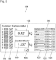
- the printing inks existing in the eight inking units of the printing press are numbered consecutively from 1 to 8 and additionally symbolized by corresponding color areas 94.
- a key 96 allows to select an ink (spot color) whose composition is corrected shall be.
- the color patch 94 for the ink # 3 is in FIG Fig. 5 highlighted. This means that this ink is being corrected.
- the rightmost part of the display shows the name of the color to be corrected "spot color xyz" and the corresponding inking unit "FW 3" in the topmost line 98.
- eight correction colors “yellow”, “orange”, “red”, “magenta”, “green”, “blue”, “cyan” and “black” are available whose names are shown in fields 100 in the lines below line 98.
- To the right are each a field 102 with a weight indication and a button 104, with which the respective correction color can be selected.
- the correction colors are processed in sequence.
- the correction colors "yellow” to "green” have already been filled into the mixing cups in the respectively correct amounts, and with the key 104 the next correction color "blue” has been activated.
- Panel 102 indicates the amount of paint that still needs to be poured into the mixing cup. The same quantity is also in a field 106 in the left part of the display. However, while the display in field 106 indicates the total amount of correction color to be added and thus remains constant as long as the correction color "blue” is selected, the display in panel 102 decreases as much as color in the mixing cup on the balance is poured. The correct amount of color is thus reached as soon as the display in field 102 has decreased to zero. With the button 104 can then be switched to the next correction color.
- the corrected composition and the new total weight will be stored again in the correction calculator 48 or elsewhere in the controller 40 so that the corrected composition will be used for later post-corrections if they prove necessary can.
Landscapes
- Inking, Control Or Cleaning Of Printing Machines (AREA)
Applications Claiming Priority (1)
| Application Number | Priority Date | Filing Date | Title |
|---|---|---|---|
| DE202015101700.6U DE202015101700U1 (de) | 2015-04-07 | 2015-04-07 | Rotationsdruckmaschine |
Publications (1)
| Publication Number | Publication Date |
|---|---|
| EP3078495A1 true EP3078495A1 (fr) | 2016-10-12 |
Family
ID=55642341
Family Applications (1)
| Application Number | Title | Priority Date | Filing Date |
|---|---|---|---|
| EP16163099.1A Withdrawn EP3078495A1 (fr) | 2015-04-07 | 2016-03-31 | Presse rotative |
Country Status (2)
| Country | Link |
|---|---|
| EP (1) | EP3078495A1 (fr) |
| DE (1) | DE202015101700U1 (fr) |
Cited By (1)
| Publication number | Priority date | Publication date | Assignee | Title |
|---|---|---|---|---|
| WO2020234003A1 (fr) * | 2019-05-20 | 2020-11-26 | Bobst Bielefeld Gmbh | Système d'impression et procédé pour ajuster une recette d'encre d'un système d'impression |
Families Citing this family (1)
| Publication number | Priority date | Publication date | Assignee | Title |
|---|---|---|---|---|
| DE102016119292A1 (de) | 2016-10-11 | 2018-04-12 | BST eltromat International GmbH | Verfahren zum Prüfen einer Funktionseinheit für den Einsatz an einer laufenden Materialbahn |
Citations (6)
| Publication number | Priority date | Publication date | Assignee | Title |
|---|---|---|---|---|
| DE102007059176A1 (de) * | 2007-12-06 | 2009-06-10 | Windmöller & Hölscher Kg | Vorrichtung und ein Verfahren zur Farbmassen- und Viskositätsermittlung an einer Druckmaschine zur Farbkorrektur |
| EP1453679B1 (fr) | 2001-12-04 | 2009-11-18 | Windmöller & Hölscher KG | Machine d'impression d'emballages a fonction de comparaison automatique integree entre l'image imprimee et l'image theorique |
| EP1916102B1 (fr) | 2006-10-23 | 2010-03-03 | Fischer & Krecke GmbH | Procédé, dispositif de montage et unité de control pour ajuster un cylindre dans une machine à imprimer |
| DE102007032944B4 (de) | 2007-07-14 | 2011-10-20 | Christian Nelissen | Verfahren zur Festlegung von Parametern eines Druckprozesses zur Erzeugung standadisierter Drucke |
| WO2012150136A2 (fr) * | 2011-05-05 | 2012-11-08 | Koenig & Bauer Aktiengesellschaft | Systèmes d'évaluation d'un exemplaire de produit sur le poste de conduite d'une machine à imprimer |
| EP2749414A1 (fr) * | 2012-12-31 | 2014-07-02 | Goss International Americas, Inc. | Commande de bande afin de réduire des déchets et procédé correspondant |
Family Cites Families (4)
| Publication number | Priority date | Publication date | Assignee | Title |
|---|---|---|---|---|
| DE3924989A1 (de) * | 1989-07-28 | 1991-02-07 | Roland Man Druckmasch | Vorrichtung zur durchfuehrung einer umfassenden qualitaetskontrolle an druckbogen |
| DE19939154A1 (de) * | 1999-08-20 | 2001-04-12 | Techkon Gmbh | Verfahren und Meßvorrichtung zur Druckkontrolle und Bildanalyse |
| US6342952B1 (en) * | 1999-10-11 | 2002-01-29 | Flint Ink Corporation | Method for matching printing ink colors |
| DE102007059177B4 (de) * | 2007-12-06 | 2011-07-14 | Windmöller & Hölscher KG, 49525 | Vorrichtung und Verfahren zur Regelung der Zusammensetzung der Druckfarbe an einer Druckmaschine |
-
2015
- 2015-04-07 DE DE202015101700.6U patent/DE202015101700U1/de not_active Expired - Lifetime
-
2016
- 2016-03-31 EP EP16163099.1A patent/EP3078495A1/fr not_active Withdrawn
Patent Citations (6)
| Publication number | Priority date | Publication date | Assignee | Title |
|---|---|---|---|---|
| EP1453679B1 (fr) | 2001-12-04 | 2009-11-18 | Windmöller & Hölscher KG | Machine d'impression d'emballages a fonction de comparaison automatique integree entre l'image imprimee et l'image theorique |
| EP1916102B1 (fr) | 2006-10-23 | 2010-03-03 | Fischer & Krecke GmbH | Procédé, dispositif de montage et unité de control pour ajuster un cylindre dans une machine à imprimer |
| DE102007032944B4 (de) | 2007-07-14 | 2011-10-20 | Christian Nelissen | Verfahren zur Festlegung von Parametern eines Druckprozesses zur Erzeugung standadisierter Drucke |
| DE102007059176A1 (de) * | 2007-12-06 | 2009-06-10 | Windmöller & Hölscher Kg | Vorrichtung und ein Verfahren zur Farbmassen- und Viskositätsermittlung an einer Druckmaschine zur Farbkorrektur |
| WO2012150136A2 (fr) * | 2011-05-05 | 2012-11-08 | Koenig & Bauer Aktiengesellschaft | Systèmes d'évaluation d'un exemplaire de produit sur le poste de conduite d'une machine à imprimer |
| EP2749414A1 (fr) * | 2012-12-31 | 2014-07-02 | Goss International Americas, Inc. | Commande de bande afin de réduire des déchets et procédé correspondant |
Cited By (5)
| Publication number | Priority date | Publication date | Assignee | Title |
|---|---|---|---|---|
| WO2020234003A1 (fr) * | 2019-05-20 | 2020-11-26 | Bobst Bielefeld Gmbh | Système d'impression et procédé pour ajuster une recette d'encre d'un système d'impression |
| CN113874217A (zh) * | 2019-05-20 | 2021-12-31 | 博斯特比勒费尔德有限公司 | 印刷系统及调整印刷系统油墨配方的方法 |
| US20220203697A1 (en) * | 2019-05-20 | 2022-06-30 | Bobst Bielefeld Gmbh | Printing system and method for adjusting an ink recipe of a printing system |
| CN113874217B (zh) * | 2019-05-20 | 2024-03-15 | 博斯特比勒费尔德有限公司 | 印刷系统及调整印刷系统油墨配方的方法 |
| US12103298B2 (en) * | 2019-05-20 | 2024-10-01 | Bobst Bielefeld Gmbh | Printing system and method for adjusting an ink recipe of a printing system |
Also Published As
| Publication number | Publication date |
|---|---|
| DE202015101700U1 (de) | 2016-07-08 |
Similar Documents
| Publication | Publication Date | Title |
|---|---|---|
| DE3331208C2 (fr) | ||
| DE2727426A1 (de) | Vorrichtung zum steuern der farbfuehrung an rotationsdruckmaschinen | |
| CH646190A5 (de) | Verfahren zur herstellung eines vorlagengetreuen farbengemisches fuer den papierdruck. | |
| DE10013876A1 (de) | Verfahren zum Regeln der Farbgebung beim Drucken mit einer Druckmaschine | |
| DE3835221A1 (de) | Verfahren zur bestimmung des verbrauchs von druckfarbe in einer offsetdruckmaschine | |
| DE2343855C3 (de) | Einrichtung zum Vorjustieren der Formzylinder von Mehrfarbenrollenrotationsdruckmaschinen | |
| EP0706885A1 (fr) | Procédé pour la formation d'une couche d'encre d'une épaisseur orientée vers l'impression continue dans une unité d'encrage | |
| EP3078496B1 (fr) | Presse rotative | |
| EP3078495A1 (fr) | Presse rotative | |
| WO2014020083A2 (fr) | Procédé de réglage de la longueur d'impression d'une image d'impression dans une rotative polychrome | |
| EP2186640B1 (fr) | Presse d'emballage dotée d'une fonction de comparaison automatique intégrée entre l'image imprimée et l'image prévue | |
| DE102007059175A1 (de) | Extrapolation densitometrischer Messwerte in nicht gemessenen Wellenlängenbereichen | |
| DE10333625B4 (de) | Verfahren und Vorrichtung zur Messung und Regelung der Konzentration von chemischen Verbindungen im Feuchtwasser beim Offsetdruck | |
| DE19906078B4 (de) | Verfahren zur Steuerung des Füllstandes für Druckfarbe in einem Farbkasten | |
| DE20105481U1 (de) | Farbversorgungseinrichtung | |
| DE4424591C1 (de) | Vorrichtung zur Zufuhr von Druckfarbe aus einer Farbspendereinrichtung in einen Farbkasten | |
| DE744927C (de) | Registerstellvorrichtung fuer Rotationsdruckmaschinen, insbesondere Rotationstiefdruckmaschinen | |
| DE102007059177B4 (de) | Vorrichtung und Verfahren zur Regelung der Zusammensetzung der Druckfarbe an einer Druckmaschine | |
| EP2988938B1 (fr) | Procédé d'ajustement de couleurs | |
| DE3828182A1 (de) | Verfahren zur einstellung der feuchte bei einer rollen-nassoffset-druckmaschine | |
| DE102005003372A1 (de) | Verfahren und Vorrichtung zum Regeln der Konzentration von Komponenten von Additiven in einer Druck- Prozessflüssigkeit | |
| DE3634811A1 (de) | Verfahren und schaltungsanordnung zum normierten anzeigen der druckfarbenzufuhr | |
| EP2295248B1 (fr) | Procédé et dispositif de détermination du comportement spécifique de transfert d'encre d'un cylindre de transfert d'encre | |
| DE767019C (de) | Vorrichtung zur Farbfuehrung fuer Rotationsschablonendrucker | |
| DE19928200A1 (de) | Verfahren zur Steuerung des Farbniveaus im Farbkasten einer Bogenoffsetdruckmaschine |
Legal Events
| Date | Code | Title | Description |
|---|---|---|---|
| PUAI | Public reference made under article 153(3) epc to a published international application that has entered the european phase |
Free format text: ORIGINAL CODE: 0009012 |
|
| AK | Designated contracting states |
Kind code of ref document: A1 Designated state(s): AL AT BE BG CH CY CZ DE DK EE ES FI FR GB GR HR HU IE IS IT LI LT LU LV MC MK MT NL NO PL PT RO RS SE SI SK SM TR |
|
| AX | Request for extension of the european patent |
Extension state: BA ME |
|
| 17P | Request for examination filed |
Effective date: 20170322 |
|
| RBV | Designated contracting states (corrected) |
Designated state(s): AL AT BE BG CH CY CZ DE DK EE ES FI FR GB GR HR HU IE IS IT LI LT LU LV MC MK MT NL NO PL PT RO RS SE SI SK SM TR |
|
| STAA | Information on the status of an ep patent application or granted ep patent |
Free format text: STATUS: THE APPLICATION IS DEEMED TO BE WITHDRAWN |
|
| 18D | Application deemed to be withdrawn |
Effective date: 20170413 |