EP3078512B1 - Rutschfeste vorrichtung für kraftfahrzeugreifen - Google Patents
Rutschfeste vorrichtung für kraftfahrzeugreifen Download PDFInfo
- Publication number
- EP3078512B1 EP3078512B1 EP16162485.3A EP16162485A EP3078512B1 EP 3078512 B1 EP3078512 B1 EP 3078512B1 EP 16162485 A EP16162485 A EP 16162485A EP 3078512 B1 EP3078512 B1 EP 3078512B1
- Authority
- EP
- European Patent Office
- Prior art keywords
- torque arm
- bolt
- vehicle wheel
- motor vehicle
- slip device
- Prior art date
- Legal status (The legal status is an assumption and is not a legal conclusion. Google has not performed a legal analysis and makes no representation as to the accuracy of the status listed.)
- Active
Links
Images



Classifications
-
- B—PERFORMING OPERATIONS; TRANSPORTING
- B60—VEHICLES IN GENERAL
- B60C—VEHICLE TYRES; TYRE INFLATION; TYRE CHANGING; CONNECTING VALVES TO INFLATABLE ELASTIC BODIES IN GENERAL; DEVICES OR ARRANGEMENTS RELATED TO TYRES
- B60C27/00—Non-skid devices temporarily attachable to resilient tyres or resiliently-tyred wheels
- B60C27/06—Non-skid devices temporarily attachable to resilient tyres or resiliently-tyred wheels extending over the complete circumference of the tread, e.g. made of chains or cables
- B60C27/10—Non-skid devices temporarily attachable to resilient tyres or resiliently-tyred wheels extending over the complete circumference of the tread, e.g. made of chains or cables having tensioning means
-
- B—PERFORMING OPERATIONS; TRANSPORTING
- B60—VEHICLES IN GENERAL
- B60C—VEHICLE TYRES; TYRE INFLATION; TYRE CHANGING; CONNECTING VALVES TO INFLATABLE ELASTIC BODIES IN GENERAL; DEVICES OR ARRANGEMENTS RELATED TO TYRES
- B60C27/00—Non-skid devices temporarily attachable to resilient tyres or resiliently-tyred wheels
- B60C27/06—Non-skid devices temporarily attachable to resilient tyres or resiliently-tyred wheels extending over the complete circumference of the tread, e.g. made of chains or cables
- B60C27/061—Non-skid devices temporarily attachable to resilient tyres or resiliently-tyred wheels extending over the complete circumference of the tread, e.g. made of chains or cables provided with radial arms for supporting the ground engaging parts on the tread
-
- B—PERFORMING OPERATIONS; TRANSPORTING
- B60—VEHICLES IN GENERAL
- B60C—VEHICLE TYRES; TYRE INFLATION; TYRE CHANGING; CONNECTING VALVES TO INFLATABLE ELASTIC BODIES IN GENERAL; DEVICES OR ARRANGEMENTS RELATED TO TYRES
- B60C27/00—Non-skid devices temporarily attachable to resilient tyres or resiliently-tyred wheels
- B60C27/06—Non-skid devices temporarily attachable to resilient tyres or resiliently-tyred wheels extending over the complete circumference of the tread, e.g. made of chains or cables
- B60C27/062—Non-skid devices temporarily attachable to resilient tyres or resiliently-tyred wheels extending over the complete circumference of the tread, e.g. made of chains or cables provided with fastening means
- B60C27/063—Non-skid devices temporarily attachable to resilient tyres or resiliently-tyred wheels extending over the complete circumference of the tread, e.g. made of chains or cables provided with fastening means acting on the wheel, e.g. on the rim or wheel bolts
Definitions
- the present invention relates to the field of anti-skid devices for motor vehicle wheel tires.
- Such devices are generally in the form of a raceway comprising means having anti-slip properties, said raceway being held in position on the tread of the tire.
- Such anti-slip devices are thus used on vehicle wheels in the event of snow or ice on the roadway.
- the invention is more particularly a front-end anti-slip device, that is to say fixed on the visible surface of the rim of a motor vehicle wheel.
- a device comprises radial arms, secured to a central member, itself attached to the rim of the wheel.
- This central member is intended to transmit to the radial arms a plating force against the outer side of the tire, thereby inducing the maintenance of the raceway located at their end on the tread of the tire concerned.
- Such a torque makes it possible to flexibly bias the radial arms and thus to press the raceway against the tread of the tire in question.
- the invention is more particularly directed towards the device for fixing the central member on the rim of the wheel in question.
- the objective of the present invention is to greatly simplify the implementation of such a front-end anti-slip device.
- the invention consists in allowing the coupling of the torque arm and the fixing bolt to be detached, so as to allow the user, when he wishes to put in place the anti-slip device of the invention, any first screwing said bolt on one of the nuts of the rim considered and then and only after effective fixing of said bolt, report the torque arm on the end of said bolt, so consecutively, to proceed with the establishment of said anti-skid device on the tire under consideration. It is conceivable in fact the usefulness of such a device that drastically simplifies the operation of setting up a front chain on a tire.
- the torque arm has a through opening, partially closed by means of a rigid blade provided with a light itself through, sliding within the torque arm in a direction perpendicular to the axis of revolution of the bolt, and maintained by default in the partial closure position of the through opening of the torque arm, this blade being intended to cooperate with the annular groove of the bolt.
- said blade cooperates with a spring, especially wire, for the purpose of ensuring the default maintenance of the blade in the closed position.
- the blade has an external projection, emerging from the torque arm and operable by the user to release the through opening and corollary, to ensure the joining / disconnection of the torque arm. on and off the mounting bolt.
- the free end of the fastening bolt has an opening of non-circular cross section, adapted to cooperate with a tool, and in particular a key of corresponding shape, hexagonal key type, for the purpose of securing or detaching on and off one of the rim nuts.
- This key is advantageously reversibly fixable within the torque arm, provided for this purpose with a housing, or is integrated in the arm, in particular by molding, the latter then acting as the handle of the key.
- the upper end of the fastening bolt that is to say opposite to the fastening zone on the rim nut, adopts a polygonal profile, and in particular hexagonal, and the through opening formed in the torque arm and complementary shape, thereby promoting the orientation of the torque arm relative to said clamping bolt.
- the torque arm comprises a round locking wire with elastic return effect in the direction of a through-hole formed within said torque arm and intended to receive said free end of the bolt of fixation, said wire now by default in operative locking position the bolt on the torque arm by cooperation with the annular groove, and being operable by the user to allow the detachment of the torque arm out of the locking bolt.
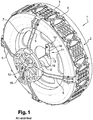
- this non-slip device 1 comprises a central flange 8 , from which radial arms 5 extend, in this case four in the example described.
- the device further comprises mechanical means associated with the central flange 8 and more particularly intended to ensure the plating of the radial arms 5 against the outer side of said tire.
- the axial force transmitted to the central plate 8 due to the implementation of these mechanical means, can generate a plating force to the radial arms 5 , and corollary, to maintain the correct position of the raceway of the anti-slip device on the tread of the tire of the vehicle wheel.
- this raceway consists of a plurality of non-slip elements 3 , typically polyurethane pads joined together by means of connecting elements 4 .
- this tread could also be made of a metal strip, textile or other.
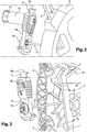
- the mechanical means for fixing the central flange 8 on the vehicle wheel typically consist of a traction member, in this case flexible 10 , secured to a torque arm 14 , itself secured to a fastening bolt 12 fit to settle on one nuts of the rim 7 of the wheel in question.
- This flexible traction member 10 can be actuated by means of a power-on lever 16 that can be actuated by the user once the bolt 12 is fastened to a nut of the rim 7 , and thus, ensuring that the flange 8 is pressed against the rim 7 , and therefore corollary radial arms 5 against the outer side of the tire considered.
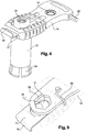
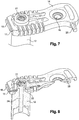
- the fixing bolt 12 is releasably separable from the torque arm 14 and this, by simple pressure by the user on a tongue 18 actuating a blade 17 , as described in more detail in connection with the Figures 5 to 8 .
- the torque arm 14 comprises a through-light 26 , allowing the insertion of the upper end of the fixing bolt 12 .
- Said bolt has, in the vicinity of its upper end, an annular groove 22 intended to cooperate, when the bolt is introduced into the through-light 26 with a blade 17 sliding in the plane of the torque arm 14 , and therefore substantially perpendicular to the the axis of revolution of the bolt 12
- the torque arm is provided with grooves (not shown) adapted to receive said blade 17 .
- This blade 17 is itself provided with a partially through aperture 19 , so as to partially close the light 26 .
- the blade 17 under the action of the user at a curved projection 18 , thus makes it possible to release the cooperation of said blade 17 with the annular groove 22 formed in the vicinity of the upper end of the fixing bolt 12 .
- the blade 17 is kept in the partial closure position, that is to say, in cooperation with the annular groove 22 of the fixing bolt 12 .
- it is subjected to the action of a wire spring 20 , whose end cooperates with an inclined plane 23 as can be observed on the figure 5 .
- the user simply presses on the projection 18 , inducing the sliding of the blade 17 and, consequently, the release of the groove 22 .
- said nut comprises jaws or clamps 15 whose retraction within the cylindrical body of the bolt 12 allows effective clamping around a nut of the rim, and therefore a universal adaptation to all dimensions of nuts.
- This retraction, for fixing the bolt 12 or on the contrary, the output of the clamps 15 out of the bolt is achieved by means of a screw 24 operable at the upper end 21 of the bolt, in this case, defining a volume with hexagonal cross section, able to cooperate with a hexagon key 25 .
- the upper end 21 is accessible because of the light 26 present within the torque arm 14 .
- this hexagon key 25 is molded into the body of the torque arm 14 .
- the torque arm 14 not only fulfills its primary function, transfer in centralized position of the clamping action of the flange against the rim, also the key function, and more specifically the handle of the key 25 .
- the torque arm 14 has a through hole 16 , at the end opposite to that provided with the through opening 26 , and able to receive the end end 13 of the drawstring 10 .
- the key 25 is disengaged from the torque arm 14 , the latter then being provided with housings provided for this purpose, in which said key is simply clipped / unclipped.
- the free end of the fastening bolt 12 adopts a hexagonal profile intended to cooperate with a profile of complementary shape defining the through opening 26 of the torque arm. More specifically, the free end 27 is divided into two zones because of the annular groove 22 intended, as already said to cooperate with the blade 17 .
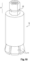
- the reversible fastening system is no longer constituted by a blade, but by a wire 32 , of circular diameter in this case, intended to cooperate with an annular groove 29 formed in the vicinity of the upper end 28 of the fixing bolt 12 .
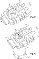
- This wire 32 integral with the torque arm 14 , also acts as a spring, and because of its positioning (see figure 15 ), tends, in the absence of external stress, to fall back towards the center of the through opening 26 formed within said torque arm, and therefore, when the fixing bolt is present, to be housed in the annular groove 29 .
- the upper end 28 of the attachment bolt comprises a zone 30 of hexagonal profile, in order to cooperate with a shape profile complementary to the through opening 26 of the torque arm. It is extended by a frustoconical portion 31 , the profile of which promotes the sliding of the wire 32 , until it comes to be housed in the annular groove 29 when the arm is secured to the bolt.
- the detachment of the torque arm from the bolt is effected by simply actuating a tongue 33 secured to the wire 32 , in a direction perpendicular to the bolt, the deflection of the wire 32 being made possible by the presence of a light 34 within torque arm (see figure 16 ).
Landscapes
- Engineering & Computer Science (AREA)
- Mechanical Engineering (AREA)
- Tires In General (AREA)
Claims (10)
- Rutschfeste Vorrichtung (1) für Kraftfahrzeugreifen, bestehend aus:• einer Führungsfläche (3, 4), die dazu bestimmt ist, gegen die Laufbahn eines Reifens eines Kraftfahrzeugrades gepresst zu werden;• radiale Arme (5), mit denen diese Führungsfläche auf der Laufbahn dieses Reifens gehalten werden kann, wobei diese Arme mit einem Zentralorgan (8) verbunden sind, das auf der Felge (7) des entsprechenden Rades über eine Baugruppe befestigt ist, die an einer der Muttern dieser Felge befestigt werden kann und die besteht:• aus einem Befestigungsbolzen (12) auf dieser Mutter, vorgesehen in der Nähe des freien Endstücks einer ringförmigen Nut (22, 29);• eine Drehmomentstütze (14), die auf dem freien Endstück dieses Bolzens abnehmbar befestigt und senkrecht zur Drehachse des Bolzens angeordnet ist;• einem Zugelement (10), das in der Nähe des anderen Endstücks dieses Arms befestigt ist;dadurch gekennzeichnet, dass die Drehmomentstütze mit Mitteln (17, 32, 33, 34) ausgerüstet ist, die mit der Ringnut kooperieren können, um den Befestigungsbolzen auf der Drehmomentstütze zu befestigen / zu lösen.
- Rutschfeste Vorrichtung für Kraftfahrzeugreifen gemäß Anspruch 1, dadurch gekennzeichnet, dass die Drehmomentstütze (14) eine durchführende Öffnung (26) enthält, die teilweise mittels einer starren Klinge (17) verschließbar ist, die mit einer Öffnung versehen ist, die selbst wiederum durchgehend (19) ist, wobei diese Klinge innerhalb der Drehmomentstütze (14) in einer Richtung senkrecht zur Drehachse des Befestigungsbolzens (12) verschiebbar montiert ist und standardmäßig in der teilweisen Verschlussposition der durchführende Öffnung (26) der Drehmomentstütze (14) gehalten wird, wobei diese Klinge dazu bestimmt ist, mit der Ringnut (22) des Bolzens zu kooperieren.
- Rutschfeste Vorrichtung für Kraftfahrzeugreifen gemäß Anspruch 2, dadurch gekennzeichnet, dass die Klinge (17) mit einer Feder (20), insbesondere Drahtfeder, kooperiert, um dafür zu sorgen, dass die Klinge (7) standardmäßig in der Verschlussposition der Öffnung (26) der Drehmomentstütze (14) bleibt.
- Rutschfeste Vorrichtung für Kraftfahrzeugreifen gemäß einem der Ansprüche 2 und 3, dadurch gekennzeichnet, dass die Klinge (17) einen äußeren Vorsprung (18) aufweist, der aus der Drehmomentstütze (14) herausragt und vom Benutzer betätigt werden kann, um die durchführende Öffnung (26) freizugeben und die Befestigung oder das Lösen der Drehmomentstütze (14) auf und außerhalb des Befestigungsbolzens (12) zu gewährleisten.
- Rutschfeste Vorrichtung für Kraftfahrzeugreifen gemäß einem der Ansprüche 2 bis 4, dadurch gekennzeichnet, dass das obere Endstück des Befestigungsbolzens ein polygonales Profil, insbesondere hexagonal, hat und dass die durchführende Öffnung (26), die innerhalb der Drehmomentstütze ausgespart ist, eine komplementäre Form hat.
- Rutschfeste Vorrichtung für Kraftfahrzeugreifen gemäß Anspruch 1, dadurch gekennzeichnet, dass die Drehmomentstütze (14), einen Verriegelungsdraht (32) mit elastischer Rückstellwirkung in Richtung einer durchführenden Öffnung (26) aufweist, die innerhalb dieser Drehmomentstütze ausgespart ist und zur Aufnahme dieses freien Endstücks des Befestigungsbolzens bestimmt ist, wobei sich dieser Verriegelungsdraht (32) standardmäßig in einer operativen Position der Sperrung des Bolzens auf der Drehmomentstütze durch Kooperation mit der Ringnut (29) befindet.
- Rutschfeste Vorrichtung für Kraftfahrzeugreifen gemäß Anspruch 6, dadurch gekennzeichnet, dass der Verriegelungsdraht (32) vom Benutzer mittels einer Zunge (33) betätigt werden kann, um die Drehmomentstütze vom Verriegelungsbolzen zu lösen.
- Rutschfeste Vorrichtung für Kraftfahrzeugreifen gemäß einem der Ansprüche 1 bis 7, dadurch gekennzeichnet, dass das freie Endstück des Befestigungsbolzens (12) eine Öffnung (21) mit einem nicht kreisförmigen Querschnitt aufweist, die mit einem Werkzeug, insbesondere einem Schlüssel entsprechender Form (25), kooperieren kann, um die Befestigung oder das Lösen des Befestigungsbolzens an und von einer der Muttern der Felge (7) zu gewährleisten.
- Rutschfeste Vorrichtung für Kraftfahrzeugreifen gemäß Anspruch 8, dadurch gekennzeichnet, dass der Schüssel (25) innerhalb der Drehmomentstütze (14) lösbar befestigt ist, die zu diesem Zweck mit Aussparungen versehen ist.
- Rutschfeste Vorrichtung für Kraftfahrzeugreifen gemäß Anspruch 8, dadurch gekennzeichnet, dass der Schlüssel (25) in die Drehmomentstütze (14) insbesondere durch Guss integriert ist, wobei diese dann als Schlüsselgriff dient.
Applications Claiming Priority (1)
| Application Number | Priority Date | Filing Date | Title |
|---|---|---|---|
| FR1553000A FR3034710B1 (fr) | 2015-04-08 | 2015-04-08 | Dispositif antiderapant pour roue de vehicule automobile |
Publications (2)
| Publication Number | Publication Date |
|---|---|
| EP3078512A1 EP3078512A1 (de) | 2016-10-12 |
| EP3078512B1 true EP3078512B1 (de) | 2018-06-27 |
Family
ID=53177683
Family Applications (1)
| Application Number | Title | Priority Date | Filing Date |
|---|---|---|---|
| EP16162485.3A Active EP3078512B1 (de) | 2015-04-08 | 2016-03-25 | Rutschfeste vorrichtung für kraftfahrzeugreifen |
Country Status (2)
| Country | Link |
|---|---|
| EP (1) | EP3078512B1 (de) |
| FR (1) | FR3034710B1 (de) |
Family Cites Families (4)
| Publication number | Priority date | Publication date | Assignee | Title |
|---|---|---|---|---|
| DE3844494A1 (de) * | 1988-12-30 | 1990-07-05 | Rud Ketten Rieger & Dietz | Gleitschutzvorrichtung |
| DE10137512C1 (de) | 2001-07-26 | 2003-03-27 | Rud Ketten Rieger & Dietz | Gleitschutzvorrichtung für Fahrzeugräder |
| DE102009004805B4 (de) * | 2009-01-13 | 2014-11-06 | Rud Ketten Rieger & Dietz Gmbh U. Co. Kg | Gleitschutzvorrichtung mit Felgenanbindung |
| DE102009059997A1 (de) * | 2009-12-21 | 2011-06-22 | RUD Ketten Rieger & Dietz GmbH u. Co. KG, 73432 | Fliehkraftverriegelungselement für Gleitschsutzvorrichtungen |
-
2015
- 2015-04-08 FR FR1553000A patent/FR3034710B1/fr not_active Expired - Fee Related
-
2016
- 2016-03-25 EP EP16162485.3A patent/EP3078512B1/de active Active
Non-Patent Citations (1)
| Title |
|---|
| None * |
Also Published As
| Publication number | Publication date |
|---|---|
| FR3034710A1 (fr) | 2016-10-14 |
| EP3078512A1 (de) | 2016-10-12 |
| FR3034710B1 (fr) | 2018-08-17 |
Similar Documents
| Publication | Publication Date | Title |
|---|---|---|
| EP0497655B1 (de) | Radzierblende, insbesondere für Kraftfahrzeuge | |
| EP0300538B1 (de) | Vorrichtung zur positiven Befestigung einer Radzierblende an einer Kraftfahrzeugradfelge | |
| EP2396182B1 (de) | Antirutschvorrichtung für den reifen eines fahrzeugrades | |
| FR3033252A1 (fr) | Bloqueur sur corde equipe d'une came a ressort perfectionne | |
| FR2716422A1 (fr) | Dispositif de fixation d'un cycle pour un porte-cycle et porte-cycle comprenant un tel dispositif. | |
| EP1896303A1 (de) | Mittel zur befestigung eines antriebsmechanismus einer wischervorrichtung an einem körpergehäuseelement | |
| LU102432B1 (fr) | Point de levage pivotant pour le levage de charges | |
| EP3033291B1 (de) | Drehender hebering mit verriegelungswerkzeug | |
| EP2816251A1 (de) | Bremse für Luftfahrzeugreifen, insbesondere für Hubschrauber | |
| EP3078512B1 (de) | Rutschfeste vorrichtung für kraftfahrzeugreifen | |
| JP2006036185A (ja) | スノーチェーン用逆止ブロックとこれを用いたスノーチェーン | |
| EP2995479B1 (de) | Rutschfeste vorrichtung für kraftfahrzeugreifen | |
| EP2366275B1 (de) | Vorrichtung zur Messerbefestigung auf den Rotor eines Böschungsmähers | |
| EP2730487B1 (de) | Haltebauteil für zwei gegeneinander befestigte Karosserieelemente eines Kraftfahrzeugs | |
| EP3966074B1 (de) | Vorrichtung zum befestigen einer zierkappe an einem hinteren lichtgehäuse für kraftfahrzeuge und verfahren zur montage mittels dieser vorrichtung | |
| EP2860094A1 (de) | Befestigungsvorrichtung eines abnehmbaren Radelements auf einem Rad, und Verwendung einer solchen Vorrichtung | |
| EP2221494A1 (de) | Vorrichtung zur Fixierung eines Radiallagers einer Getriebewelle eines Kraftfahrzeuges | |
| EP1338445A1 (de) | Vorrichtung zur Befestigung von einem Modul eines Reifenüberwachungssystem auf ein Rad | |
| EP1477331B1 (de) | Radanordnung insbesondere für mit Laufrädern versehenen Müllbehälter | |
| EP0893333B1 (de) | Verbindungsvorrichtung für Glied einer Gleiskette | |
| FR2547247A1 (fr) | Dispositif de guidage pour la mise en place d'une roue sur l'essieu d'un vehicule automobile | |
| FR2882967A3 (fr) | Corps de bague pour s'adapter au rayon d'ecartement d'un element d'un vehicule | |
| WO2007025615A1 (fr) | Balai d’essuie-glace plat notamment pour dispositif d’essuyage de vehicule automobile | |
| FR3057210A1 (fr) | Dispositif de demontage et de remontage d’un pneumatique dans une jante | |
| FR3055126A1 (fr) | Systeme de serrage debrayage pour roue ou tige de selle de velo |
Legal Events
| Date | Code | Title | Description |
|---|---|---|---|
| PUAI | Public reference made under article 153(3) epc to a published international application that has entered the european phase |
Free format text: ORIGINAL CODE: 0009012 |
|
| AK | Designated contracting states |
Kind code of ref document: A1 Designated state(s): AL AT BE BG CH CY CZ DE DK EE ES FI FR GB GR HR HU IE IS IT LI LT LU LV MC MK MT NL NO PL PT RO RS SE SI SK SM TR |
|
| AX | Request for extension of the european patent |
Extension state: BA ME |
|
| STAA | Information on the status of an ep patent application or granted ep patent |
Free format text: STATUS: REQUEST FOR EXAMINATION WAS MADE |
|
| 17P | Request for examination filed |
Effective date: 20170203 |
|
| RBV | Designated contracting states (corrected) |
Designated state(s): AL AT BE BG CH CY CZ DE DK EE ES FI FR GB GR HR HU IE IS IT LI LT LU LV MC MK MT NL NO PL PT RO RS SE SI SK SM TR |
|
| RIC1 | Information provided on ipc code assigned before grant |
Ipc: B60C 27/10 20060101ALI20171218BHEP Ipc: B60C 27/06 20060101AFI20171218BHEP |
|
| GRAP | Despatch of communication of intention to grant a patent |
Free format text: ORIGINAL CODE: EPIDOSNIGR1 |
|
| STAA | Information on the status of an ep patent application or granted ep patent |
Free format text: STATUS: GRANT OF PATENT IS INTENDED |
|
| INTG | Intention to grant announced |
Effective date: 20180213 |
|
| GRAS | Grant fee paid |
Free format text: ORIGINAL CODE: EPIDOSNIGR3 |
|
| GRAA | (expected) grant |
Free format text: ORIGINAL CODE: 0009210 |
|
| STAA | Information on the status of an ep patent application or granted ep patent |
Free format text: STATUS: THE PATENT HAS BEEN GRANTED |
|
| AK | Designated contracting states |
Kind code of ref document: B1 Designated state(s): AL AT BE BG CH CY CZ DE DK EE ES FI FR GB GR HR HU IE IS IT LI LT LU LV MC MK MT NL NO PL PT RO RS SE SI SK SM TR |
|
| REG | Reference to a national code |
Ref country code: GB Ref legal event code: FG4D Free format text: NOT ENGLISH |
|
| REG | Reference to a national code |
Ref country code: AT Ref legal event code: REF Ref document number: 1011975 Country of ref document: AT Kind code of ref document: T Effective date: 20180715 |
|
| REG | Reference to a national code |
Ref country code: IE Ref legal event code: FG4D Free format text: LANGUAGE OF EP DOCUMENT: FRENCH |
|
| REG | Reference to a national code |
Ref country code: DE Ref legal event code: R096 Ref document number: 602016003762 Country of ref document: DE |
|
| PG25 | Lapsed in a contracting state [announced via postgrant information from national office to epo] |
Ref country code: LT Free format text: LAPSE BECAUSE OF FAILURE TO SUBMIT A TRANSLATION OF THE DESCRIPTION OR TO PAY THE FEE WITHIN THE PRESCRIBED TIME-LIMIT Effective date: 20180627 Ref country code: NO Free format text: LAPSE BECAUSE OF FAILURE TO SUBMIT A TRANSLATION OF THE DESCRIPTION OR TO PAY THE FEE WITHIN THE PRESCRIBED TIME-LIMIT Effective date: 20180927 Ref country code: SE Free format text: LAPSE BECAUSE OF FAILURE TO SUBMIT A TRANSLATION OF THE DESCRIPTION OR TO PAY THE FEE WITHIN THE PRESCRIBED TIME-LIMIT Effective date: 20180627 Ref country code: BG Free format text: LAPSE BECAUSE OF FAILURE TO SUBMIT A TRANSLATION OF THE DESCRIPTION OR TO PAY THE FEE WITHIN THE PRESCRIBED TIME-LIMIT Effective date: 20180927 Ref country code: FI Free format text: LAPSE BECAUSE OF FAILURE TO SUBMIT A TRANSLATION OF THE DESCRIPTION OR TO PAY THE FEE WITHIN THE PRESCRIBED TIME-LIMIT Effective date: 20180627 |
|
| REG | Reference to a national code |
Ref country code: NL Ref legal event code: MP Effective date: 20180627 |
|
| REG | Reference to a national code |
Ref country code: LT Ref legal event code: MG4D |
|
| PG25 | Lapsed in a contracting state [announced via postgrant information from national office to epo] |
Ref country code: GR Free format text: LAPSE BECAUSE OF FAILURE TO SUBMIT A TRANSLATION OF THE DESCRIPTION OR TO PAY THE FEE WITHIN THE PRESCRIBED TIME-LIMIT Effective date: 20180928 Ref country code: RS Free format text: LAPSE BECAUSE OF FAILURE TO SUBMIT A TRANSLATION OF THE DESCRIPTION OR TO PAY THE FEE WITHIN THE PRESCRIBED TIME-LIMIT Effective date: 20180627 Ref country code: LV Free format text: LAPSE BECAUSE OF FAILURE TO SUBMIT A TRANSLATION OF THE DESCRIPTION OR TO PAY THE FEE WITHIN THE PRESCRIBED TIME-LIMIT Effective date: 20180627 Ref country code: HR Free format text: LAPSE BECAUSE OF FAILURE TO SUBMIT A TRANSLATION OF THE DESCRIPTION OR TO PAY THE FEE WITHIN THE PRESCRIBED TIME-LIMIT Effective date: 20180627 |
|
| REG | Reference to a national code |
Ref country code: AT Ref legal event code: MK05 Ref document number: 1011975 Country of ref document: AT Kind code of ref document: T Effective date: 20180627 |
|
| PG25 | Lapsed in a contracting state [announced via postgrant information from national office to epo] |
Ref country code: NL Free format text: LAPSE BECAUSE OF FAILURE TO SUBMIT A TRANSLATION OF THE DESCRIPTION OR TO PAY THE FEE WITHIN THE PRESCRIBED TIME-LIMIT Effective date: 20180627 |
|
| PG25 | Lapsed in a contracting state [announced via postgrant information from national office to epo] |
Ref country code: SK Free format text: LAPSE BECAUSE OF FAILURE TO SUBMIT A TRANSLATION OF THE DESCRIPTION OR TO PAY THE FEE WITHIN THE PRESCRIBED TIME-LIMIT Effective date: 20180627 Ref country code: AT Free format text: LAPSE BECAUSE OF FAILURE TO SUBMIT A TRANSLATION OF THE DESCRIPTION OR TO PAY THE FEE WITHIN THE PRESCRIBED TIME-LIMIT Effective date: 20180627 Ref country code: PL Free format text: LAPSE BECAUSE OF FAILURE TO SUBMIT A TRANSLATION OF THE DESCRIPTION OR TO PAY THE FEE WITHIN THE PRESCRIBED TIME-LIMIT Effective date: 20180627 Ref country code: IS Free format text: LAPSE BECAUSE OF FAILURE TO SUBMIT A TRANSLATION OF THE DESCRIPTION OR TO PAY THE FEE WITHIN THE PRESCRIBED TIME-LIMIT Effective date: 20181027 Ref country code: EE Free format text: LAPSE BECAUSE OF FAILURE TO SUBMIT A TRANSLATION OF THE DESCRIPTION OR TO PAY THE FEE WITHIN THE PRESCRIBED TIME-LIMIT Effective date: 20180627 Ref country code: CZ Free format text: LAPSE BECAUSE OF FAILURE TO SUBMIT A TRANSLATION OF THE DESCRIPTION OR TO PAY THE FEE WITHIN THE PRESCRIBED TIME-LIMIT Effective date: 20180627 Ref country code: RO Free format text: LAPSE BECAUSE OF FAILURE TO SUBMIT A TRANSLATION OF THE DESCRIPTION OR TO PAY THE FEE WITHIN THE PRESCRIBED TIME-LIMIT Effective date: 20180627 |
|
| PG25 | Lapsed in a contracting state [announced via postgrant information from national office to epo] |
Ref country code: ES Free format text: LAPSE BECAUSE OF FAILURE TO SUBMIT A TRANSLATION OF THE DESCRIPTION OR TO PAY THE FEE WITHIN THE PRESCRIBED TIME-LIMIT Effective date: 20180627 Ref country code: SM Free format text: LAPSE BECAUSE OF FAILURE TO SUBMIT A TRANSLATION OF THE DESCRIPTION OR TO PAY THE FEE WITHIN THE PRESCRIBED TIME-LIMIT Effective date: 20180627 |
|
| REG | Reference to a national code |
Ref country code: DE Ref legal event code: R097 Ref document number: 602016003762 Country of ref document: DE |
|
| PLBE | No opposition filed within time limit |
Free format text: ORIGINAL CODE: 0009261 |
|
| STAA | Information on the status of an ep patent application or granted ep patent |
Free format text: STATUS: NO OPPOSITION FILED WITHIN TIME LIMIT |
|
| PG25 | Lapsed in a contracting state [announced via postgrant information from national office to epo] |
Ref country code: DK Free format text: LAPSE BECAUSE OF FAILURE TO SUBMIT A TRANSLATION OF THE DESCRIPTION OR TO PAY THE FEE WITHIN THE PRESCRIBED TIME-LIMIT Effective date: 20180627 |
|
| 26N | No opposition filed |
Effective date: 20190328 |
|
| PG25 | Lapsed in a contracting state [announced via postgrant information from national office to epo] |
Ref country code: SI Free format text: LAPSE BECAUSE OF FAILURE TO SUBMIT A TRANSLATION OF THE DESCRIPTION OR TO PAY THE FEE WITHIN THE PRESCRIBED TIME-LIMIT Effective date: 20180627 |
|
| PG25 | Lapsed in a contracting state [announced via postgrant information from national office to epo] |
Ref country code: MC Free format text: LAPSE BECAUSE OF FAILURE TO SUBMIT A TRANSLATION OF THE DESCRIPTION OR TO PAY THE FEE WITHIN THE PRESCRIBED TIME-LIMIT Effective date: 20180627 |
|
| PG25 | Lapsed in a contracting state [announced via postgrant information from national office to epo] |
Ref country code: AL Free format text: LAPSE BECAUSE OF FAILURE TO SUBMIT A TRANSLATION OF THE DESCRIPTION OR TO PAY THE FEE WITHIN THE PRESCRIBED TIME-LIMIT Effective date: 20180627 Ref country code: LU Free format text: LAPSE BECAUSE OF NON-PAYMENT OF DUE FEES Effective date: 20190325 |
|
| REG | Reference to a national code |
Ref country code: BE Ref legal event code: MM Effective date: 20190331 |
|
| PG25 | Lapsed in a contracting state [announced via postgrant information from national office to epo] |
Ref country code: IE Free format text: LAPSE BECAUSE OF NON-PAYMENT OF DUE FEES Effective date: 20190325 |
|
| PG25 | Lapsed in a contracting state [announced via postgrant information from national office to epo] |
Ref country code: BE Free format text: LAPSE BECAUSE OF NON-PAYMENT OF DUE FEES Effective date: 20190331 |
|
| PG25 | Lapsed in a contracting state [announced via postgrant information from national office to epo] |
Ref country code: TR Free format text: LAPSE BECAUSE OF FAILURE TO SUBMIT A TRANSLATION OF THE DESCRIPTION OR TO PAY THE FEE WITHIN THE PRESCRIBED TIME-LIMIT Effective date: 20180627 |
|
| PG25 | Lapsed in a contracting state [announced via postgrant information from national office to epo] |
Ref country code: PT Free format text: LAPSE BECAUSE OF FAILURE TO SUBMIT A TRANSLATION OF THE DESCRIPTION OR TO PAY THE FEE WITHIN THE PRESCRIBED TIME-LIMIT Effective date: 20181029 Ref country code: MT Free format text: LAPSE BECAUSE OF FAILURE TO SUBMIT A TRANSLATION OF THE DESCRIPTION OR TO PAY THE FEE WITHIN THE PRESCRIBED TIME-LIMIT Effective date: 20180627 |
|
| GBPC | Gb: european patent ceased through non-payment of renewal fee |
Effective date: 20200325 |
|
| PG25 | Lapsed in a contracting state [announced via postgrant information from national office to epo] |
Ref country code: GB Free format text: LAPSE BECAUSE OF NON-PAYMENT OF DUE FEES Effective date: 20200325 |
|
| PG25 | Lapsed in a contracting state [announced via postgrant information from national office to epo] |
Ref country code: CY Free format text: LAPSE BECAUSE OF FAILURE TO SUBMIT A TRANSLATION OF THE DESCRIPTION OR TO PAY THE FEE WITHIN THE PRESCRIBED TIME-LIMIT Effective date: 20180627 |
|
| PG25 | Lapsed in a contracting state [announced via postgrant information from national office to epo] |
Ref country code: HU Free format text: LAPSE BECAUSE OF FAILURE TO SUBMIT A TRANSLATION OF THE DESCRIPTION OR TO PAY THE FEE WITHIN THE PRESCRIBED TIME-LIMIT; INVALID AB INITIO Effective date: 20160325 |
|
| PGFP | Annual fee paid to national office [announced via postgrant information from national office to epo] |
Ref country code: CH Payment date: 20220321 Year of fee payment: 7 |
|
| PG25 | Lapsed in a contracting state [announced via postgrant information from national office to epo] |
Ref country code: MK Free format text: LAPSE BECAUSE OF FAILURE TO SUBMIT A TRANSLATION OF THE DESCRIPTION OR TO PAY THE FEE WITHIN THE PRESCRIBED TIME-LIMIT Effective date: 20180627 |
|
| REG | Reference to a national code |
Ref country code: CH Ref legal event code: PL |
|
| PG25 | Lapsed in a contracting state [announced via postgrant information from national office to epo] |
Ref country code: LI Free format text: LAPSE BECAUSE OF NON-PAYMENT OF DUE FEES Effective date: 20230331 Ref country code: CH Free format text: LAPSE BECAUSE OF NON-PAYMENT OF DUE FEES Effective date: 20230331 |
|
| PGFP | Annual fee paid to national office [announced via postgrant information from national office to epo] |
Ref country code: DE Payment date: 20240307 Year of fee payment: 9 |
|
| REG | Reference to a national code |
Ref country code: DE Ref legal event code: R119 Ref document number: 602016003762 Country of ref document: DE |
|
| PG25 | Lapsed in a contracting state [announced via postgrant information from national office to epo] |
Ref country code: DE Free format text: LAPSE BECAUSE OF NON-PAYMENT OF DUE FEES Effective date: 20251001 |
|
| PGFP | Annual fee paid to national office [announced via postgrant information from national office to epo] |
Ref country code: IT Payment date: 20260310 Year of fee payment: 11 |
|
| PGFP | Annual fee paid to national office [announced via postgrant information from national office to epo] |
Ref country code: FR Payment date: 20260324 Year of fee payment: 11 |