EP3078514B1 - Système comprenant un appareil de commande et un dispositif de commande - Google Patents
Système comprenant un appareil de commande et un dispositif de commande Download PDFInfo
- Publication number
- EP3078514B1 EP3078514B1 EP16163543.8A EP16163543A EP3078514B1 EP 3078514 B1 EP3078514 B1 EP 3078514B1 EP 16163543 A EP16163543 A EP 16163543A EP 3078514 B1 EP3078514 B1 EP 3078514B1
- Authority
- EP
- European Patent Office
- Prior art keywords
- control unit
- control
- interface
- operator
- control device
- Prior art date
- Legal status (The legal status is an assumption and is not a legal conclusion. Google has not performed a legal analysis and makes no representation as to the accuracy of the status listed.)
- Active
Links
Images
Classifications
-
- B—PERFORMING OPERATIONS; TRANSPORTING
- B60—VEHICLES IN GENERAL
- B60D—VEHICLE CONNECTIONS
- B60D1/00—Traction couplings; Hitches; Draw-gear; Towing devices
- B60D1/24—Traction couplings; Hitches; Draw-gear; Towing devices characterised by arrangements for particular functions
- B60D1/26—Traction couplings; Hitches; Draw-gear; Towing devices characterised by arrangements for particular functions for remote control, e.g. for releasing
-
- B—PERFORMING OPERATIONS; TRANSPORTING
- B60—VEHICLES IN GENERAL
- B60D—VEHICLE CONNECTIONS
- B60D1/00—Traction couplings; Hitches; Draw-gear; Towing devices
- B60D1/01—Traction couplings or hitches characterised by their type
- B60D1/06—Ball-and-socket hitches
-
- B—PERFORMING OPERATIONS; TRANSPORTING
- B60—VEHICLES IN GENERAL
- B60D—VEHICLE CONNECTIONS
- B60D1/00—Traction couplings; Hitches; Draw-gear; Towing devices
- B60D1/48—Traction couplings; Hitches; Draw-gear; Towing devices characterised by the mounting
- B60D1/54—Traction couplings; Hitches; Draw-gear; Towing devices characterised by the mounting collapsible or retractable when not in use, e.g. hide-away hitches
Definitions
- the invention relates to a system comprising a control device for a trailer coupling which is arranged or can be arranged on a motor vehicle, according to the preamble of claim 1.
- control device can be operated via a mobile operating device having a graphical user interface, for example a smartphone. Operation is comfortable.
- the system is complex.
- the encryption method preferably has a continuously changing code.
- a rolling code, a changing code, a so-called jumping code or hopping code is advantageous.
- a rolling encryption method is preferred.
- the encryption can be, for example, PGP encryption (Pretty Good Privacy). Encryption with a large number of bits is preferred, expediently at least 16 bits, particularly preferably 32 bits or 64 bits.
- control device and / or operating device have at least one reading means with which they can each read in a key for the encryption means and the decryption means for the subsequent encrypted communication.
- a respective key can be permanently stored in a control device or operating device so that it does not have to be read in individually.
- control unit and the control unit can be delivered ex works as a hard-coded pair that communicates with one another.
- reading in a key individually for each system offers the advantage that a high level of individual security can be achieved.
- a so-called secret key is agreed between the operating device and the control device.
- a symmetrical key that the operating device and / or the control device know is preferred.
- next code next code
- the next code or next code can form an element of a predefined and suitably long list that is played through cyclically or iterated through. A so-called rolling code is possible in this way.
- the one-way key can for example consist of an initialization vector with a predetermined length, for example 32 bits, and an alternating code.
- a key for the encryption means of the operating device is stored on or in the control device. This means that only the control unit has to be taught in, but not the control unit. It is preferred here that the key for the control device itself does not have to be read in, that is to say, for example, is stored on or in the control device.
- the at least one reading means has an optical interface for reading in the key using an optical code, for example a barcode, a QR code or the like.
- the optical code in particular a QR code, is shown, for example, in an operating manual for the system.
- the code is expediently generated individually for each system.
- the at least one reading means can comprise a camera, a scanner, in particular a barcode scanner or the like.
- the at least one reading means has a wireless interface, namely a radio interface, to the wireless
- RFID tag can be arranged on the operating device, for example. It is also possible to include this RFID component with the key, for example in an operating manual for the system according to the invention, for example to glue it into it.
- an advantageous measure provides that the at least one reading means for reading in the key over a short distance of a maximum of 30 cm, preferably only 20 cm or 10 cm, to the memory in which the key is stored, for example the barcode or the radio transmitter , is designed. This means that the key cannot even be read in without authorization. Even greater security is achieved if the at least one reading device can only read the key at a distance of approx. 3-8 cm. It is also possible, however, for the at least one reading means to be designed for reading in the key over a greater distance of, for example, a maximum of 2 m, preferably a maximum of 1.5 m. This means that a possibly relatively poorly accessible medium in which the key is stored, for example the control unit, can nevertheless be read out.
- control device has the key for communication between the operating device and the control device, that is, for example, has a memory, in particular an electronic memory, for the key.
- the key can only be read out by the operating device in a wired manner, for example via electrical contacts.
- the key can only be read out by the operating device when direct contact is established between the control device and the operating device.
- the operating device is plugged into a plug-in receptacle of the control device so that the operating device can read out the key.
- the key can only be read out by the operating device if an operating switch or sensor on board the control device is actuated at the same time.
- the switch can, for example, be actuated manually by an operator, for example by pressing.
- the switch is on board a control board of the control device and can only be actuated through a passage opening on a housing of the control device.
- An operating tool for example a pen, ballpoint pen or the like, fits through the passage opening, so if the operator simultaneously presses or actuates the switch or button on board the control device and activates the at least one reading device of the operating device, this at least one reading device can read the key from the control device read out.
- a transmitter on board the control device is activated for sending the key to the operating device.
- the control device has a transmitter that can be activated by the operator by means of a push button, optical sensor or the like, so that he sends the key to the operator control device.
- a memory for a key for communication can be read out exclusively by wire with direct contact between the control device and control device or when a sensor or switch on board the control device is actuated and / or the control device has a transmitter for sending the key to the control device, which can be operated manually or in some other way by an operator.
- the key is stored on board the control device, so to speak, and can be adapted by the control device when paired with the control device in order to then carry out secure, encrypted communication with the control device.
- the source or the memory in which the key is stored is shielded from unauthorized reading.
- the operating device is hidden or protected from the surroundings of the motor vehicle behind a body panel, through which the memory, for example a radio transmitter with the key for the encryption, cannot be read out.
- a shield to be provided on board the control unit.
- a housing of the control device can be designed in sections as a shield so that an RFID tag can only be read from a specific position can, for example, from the vehicle interior of the motor vehicle on which or in which the control unit is arranged.
- the shield can, for example, only be open towards the interior of the motor vehicle, but closed towards the surroundings of the motor vehicle, so that the key cannot be read from the outside area, that is to say the surroundings, of the motor vehicle.
- measures are taken on the control device so that it can only be installed in such an installation position in or on the motor vehicle that the shielding is effective against the environment. If, for example, a person standing next to the motor vehicle tries to read the key, this cannot succeed.
- the control device has a shielding plate, a shielding wall or the like, which is arranged between the memory for the key and the surroundings of the motor vehicle, when the control device is mounted in an intended installation position on the motor vehicle.
- the shielding wall, the shielding plate or the like has, for example, a funnel-shaped or U-shaped shape and is open to the interior of the motor vehicle.
- the encryption is provided, so to speak, on the communication level directly between the wirelessly communicating interfaces of the control device and the operating device.
- the wireless communication so to speak the radio link or an optical communication link (infrared or the like), is already encrypted. Encryption at a higher level, for example encryption of data before it is transferred to a radio driver or optical driver (for example a Bluetooth driver), is therefore not absolutely necessary.
- the encryption works, so to speak, on a higher level, that is to say that the wireless route between the wireless interfaces of the operating device and the control device is not encrypted, for example a simple Bluetooth route. Then the encryption is at a higher level, for example between an application program or application program of the operating device and a correspondingly suitable one Program provided by the control unit.
- wireless communications that were not encrypted, for example Bluetooth, can also be provided between the operating device and the control device, for example.
- the approach according to the invention can thus also be implemented, for example, in systems in which the operating device is provided, for example, by a smartphone, a notebook or the like.
- control device has an operating interface for local operation, the operating interface only using an operating tool, for example using a pen , can be operated and / or is covered by a cover which is adjustable between an open position in which the operator interface is accessible to an operator and a closed position in which the cover closes the operator interface inaccessible to an operator.
- the so-to-speak normal or customary operation takes place via the operating device, for example its buttons.
- the control unit itself only provides an emergency operation, so to speak. This means that the control device can still be operated even if the control device fails or has been lost. Operation locally on the control device is, however, deliberately made more difficult according to an advantageous aspect in order to avoid incorrect operations. Another advantageous aspect is that almost no operating function is necessary locally on the control device, because the operating device provides this. However, the operating interface of the control device is so to speak sparse and is limited to the emergency function, so to speak. A complex construction on the control device itself, for example several buttons, acoustic signaling means or optical display means or the like, are not necessary. This functionality, which increases operating safety and / or improves convenience, is provided by the operating device.
- the control unit itself can be kept simple. The effort for relocating, for example, pushbutton switches or the like in the motor vehicle is reduced or eliminated entirely.
- the local operating interface of the control device comprises an electrical switch or sensor arranged on a control board.
- a pushbutton switch, a proximity sensor or the like can be arranged directly on a control board which, for example, controls an electric motor, a lock and / or a swivel drive of the trailer coupling.
- the structure of the control unit is particularly simple as a result. At this point, however, it should be mentioned that, in principle, a sensor, switch or other operating element for local operation of the control device can also be provided at a point other than on the control board.
- a preferred embodiment can provide that the local operating interface of the control device does not include any optical and / or acoustic output means or display means. It is thus possible, for example, for the control device to have no LEDs, no monitor or the like other optical output means on board. This function is implemented exclusively by the wirelessly communicating mobile operating device, which is remote, so to speak.
- a variant of the invention provides that the local operating interface of the control device can only be operated using an operating tool, for example a pen, in particular a ballpoint pen or the like.
- the local operating interface is designed so to speak so small or so inaccessible that it cannot be operated without the operating tool. This avoids incorrect operation.
- a passage opening for the operating tool is provided on a housing of the control device or a protective casing of the control device, through which the operating tool can operate the sensor or switch of the control device for the local operating interface.
- a ballpoint pen or other pen-like tool can act on the switch or sensor through the passage opening.
- This sensor or switch is preferably, as mentioned, on a Control board of the control unit or arranged on a control board of the control unit.
- control device has a local operating interface, but this is functionally very limited.
- the local interface is expediently restricted to an emergency function.
- the local operating interface of the control device is designed to send a key for encrypted communication between the control device and the operating device.
- a transmitter of the control device can be configured to send the key to the operating device. It is advantageous if this does not happen without certain circumstances, i.e., for example, that the switch, as explained, can only be actuated through the passage opening of the housing, for example with the aid of a ballpoint pen or the like. This prevents the control device from sending the key to an unauthorized or foreign control device, so to speak, which is not intended to actuate the trailer coupling.
- the operator must therefore actively operate the pairing of control device and operating device, for example by simultaneously actuating the control device for connecting the key to the operating device and activating the operating device for receiving the key. It is possible for these operator actions to take place sequentially, that is, a respective operation of the operator control unit and control device opens a time window in which the control device sends the key, if necessary sends it repeatedly, and in which time window the operator control device is ready to receive the key is.
- the local operating interface of the control device is concealed behind a cover which can be adjusted between an open position and a closed position. In the open position, the operator can access the local operating interface, but not in the closed position.
- the cover can, for example, be a cover of a housing of the control device be.
- the system has a cover part as the aforementioned cover or as part of the aforementioned cover, which forms part of an interior cover or interior trim of the motor vehicle. The cover part must therefore be removed or opened in a targeted manner by the operator, so to speak, ie the interior trim of the motor vehicle must be opened so that the operating interface of the control device becomes accessible.
- a combination of interior lining cover part and housing cover of a housing of the control device can be provided, that is, the operator must first open the interior lining and then open the housing of the control device in order to use the local operating interface for local operation of the control device reach.
- optical output means for displaying a function of the control means, in particular a lock or Unlocking the coupling arm and / or an adjustment of the coupling arm between a non-use position and a use position are provided.
- the optical output means can also be provided to output at least one sensor signal.
- support load values can be output via the optical output means. It is also possible that the output means only indicate whether a support load is permissible or too large, for example exceeds a limit value.
- a green light-emitting diode can indicate that the support load is OK
- a red light-emitting diode or a red optical signal can indicate that the permissible support load value has been exceeded.
- the corresponding optical output means are only provided on the operating device, but not on the control device. To the extent that optical output means are present in a system according to the invention, they can be recognized from the outside on the operating device, not on the control device. The optical output means may not be accessible or visible at all on the control unit, for example because they are hidden behind an interior lining of the motor vehicle.
- optical output means can additionally be provided on the control device, for example for a maintenance function or the like. It is thus conceivable that LEDs or the like are arranged on a control circuit board which is arranged in a housing of the control device, which LEDs or the like indicate a function of the control device. However, these LEDs or other optical display means of the control device are preferably only visible when an interior paneling of the motor vehicle is removed and / or the operator is looking through an opening in the housing of the control device. In any case, it is preferably provided that optical output means present on the control device are not visible when the control device is mounted on the vehicle.
- the optical output means of the operating device expediently comprise at least one LED.
- the optical output means signal, for example by means of a color change, for example from green to red, that the trailer coupling is unlocked. So it is beneficial to a specific one Status of the trailer coupling is assigned a predetermined optical signal of the optical output means of the operating device. So when the trailer coupling is ready to drive, ie in the position of use and locked, an optical display on the control unit lights up green, otherwise red. It is also possible for a green and red optical signal to indicate that the trailer coupling is not in the use position but in the non-use position, but is locked in the non-use position. Even simple optical signal sequences, for example a flashing status LED, can signal a function of the trailer coupling. If, for example, the coupling arm is moved from the position of use to the position of non-use or vice versa, the corresponding optical displays on the operating device, for example an LED, flash.
- the optical output means of the operating device provide feedback when an operating element of the operating interface of the operating device is actuated. If the operator presses a pushbutton switch or the like on the control unit, for example an LED or some other display means signals the respective actuation.
- a bidirectional communication concept is advantageous in which the control unit controls the control unit wirelessly and the control unit in turn reports the respective status of the trailer coupling back to the control unit, for example the coupling arm locked or unlocked and / or the coupling arm in the use position, the non-use position or an intermediate position between the use position and disuse.
- control device it is possible for the control device to have acoustic output means, for example a loudspeaker, in order to signal a function that triggers or controls the operating device. It is particularly possible here for the control device to have only acoustic output means, that is to say no optical output means. However, it is also possible for the output means of the control device to include acoustic and optical output means, the optical output means generally not being visible, for example behind a Concealed interior lining of the motor vehicle. The acoustic output means have the advantage that they can also be perceived when the control device is mounted below the motor vehicle, for example, or is hidden behind a panel of the motor vehicle. The operator hears the function that he triggers or controls via the mobile control unit.
- acoustic output means for example a loudspeaker
- a triggering process for unlocking the trailer coupling, locking the trailer coupling, a movement between the working position and the rest position or the like can be output by an acoustic signal, in particular a signal sequence.
- the operator thus receives acoustic feedback about his operating action or the function of the control device and / or trailer coupling triggered by him.
- a loudspeaker or other acoustically functioning signaling means of the control device can be arranged, for example, directly on or on a control board of the control device.
- An acoustic interface or acoustic output means are, for example, already present in a mobile phone that would be suitable as an operating device.
- the acoustic interface is controlled, for example, by a corresponding software according to the invention.
- control device is designed only for installation in an interior of the motor vehicle.
- a protective housing that would withstand environmental influences, salt, water or the like is then not present in the control device.
- the housing of the control device is just a plastic housing that has openings that are not shielded or sealed against water. This makes the construction of the control unit very simple. Protection against environmental influences is provided, so to speak, by the motor vehicle.
- the operating concept of the control device based on the wirelessly communicating operating device is particularly advantageous. Since the operating components for operating the control unit and thus the trailer coupling, for example pushbutton switches or the like, do not have to be arranged or mounted on or in the interior of the motor vehicle. This functionality is provided by the operator panel.
- an operating device with the remote control functions or display functions according to the invention can also control a control device or can be controlled by a control device, for example to display sensor values that are located outside the motor vehicle.
- the control unit expediently has a protective housing for shielding against environmental influences.
- the following measures can advantageously be provided in the operating device.
- the operating device advantageously has a local operating interface.
- the operator interface can for example comprise very simple pushbutton switches. It is thus possible that a pushbutton switch has to be pressed in order to release a lock of the trailer coupling and / or to trigger an adjustment of the coupling arm between a position of use and a position of non-use.
- a single pressure switch or sensor or other operating element can be provided on the operating interface.
- the operating interface of the operating device comprises a button or sensor, preferably two buttons or sensors, which must be operated in a certain sequence and / or simultaneously in order to trigger a function of the control means, for example to release the lock of the trailer coupling and / or its To trigger adjustment between use position and non-use position.
- the operating device is particularly compact in a preferred embodiment, so it can easily be carried along in a pocket of trousers, a jacket or the like, for example. It is precisely then that incorrect operation is not unlikely, since the operator unintentionally accesses an operating element can act. If a very specific operation is then required, i.e. that the operator presses two control elements at the same time or in a certain order or actuates a control element in a certain control sequence, for example has to press three times at short intervals, so that the actuating means of the control device become active, this is necessary Security or protection against incorrect operation can advantageously be implemented.
- a preferred operating concept provides that a button or sensor of the operating device is actuated, whereupon a time window opens within which the button or sensor must be actuated again.
- the time window is between 2 and 6 seconds, preferably 4 seconds. If within these 4 seconds or at least within the time window another key press or a corresponding further operator action occurs, the locking is triggered and / or an adjustment process of the coupling arm is initiated.
- a keystroke or an operating command that exceeds a certain duration of actuation leads to a blockage. If, for example, a button is pressed permanently, this does not lead to an unlocking and / or adjustment of the trailer coupling.
- the aforementioned concepts of operating safety can be implemented in the operating device or also in the control device or both.
- the operating device can block the sending of a control signal if the specified operating sequence is not adhered to.
- the control device it is also possible for the control device to only evaluate control signals that are within the framework of the specified safety operating concept.
- the wireless communication can be optical communication, for example based on infrared signals. Radio communication is particularly preferred. Communication in the higher frequency range, for example at least 1 GHz, particularly preferably at least 2 GHz, in particular 2.4 GHz, is advantageous. Of course, the communication can also be easily implemented at lower frequencies, for example in the range of the frequencies of 315-433 MHz customary for locking systems in motor vehicles.
- a higher frequency can enable communication between control unit and operating unit with higher data quality or the transmission of important information in a correspondingly shorter time.
- the wireless communication takes place bidirectionally between the operating device and the control device.
- the communication is unidirectional, at least with regard to data transmission, i.e., for example, only communication from the control device to the control device takes place for the transmission of sensor data or, for example, communication only from the control device to the control device to control the trailer coupling he follows.
- bidirectional communication is provided for so-called handshakes or other communication on lower communication levels, for example according to the ISO layer model on layers 1-4, while the upper layers (session layer, presentation layer and application layer / layers 4-7) only unidirectional communication between control unit and operating unit or vice versa is provided.
- the communication between the wireless interfaces, the control device, interface and the operating device interface is particularly preferably limited to a range of approximately 15 m at most, in particular approximately 10 m at most, particularly preferably to approximately 5 m. This ensures that only an operating device that is located in the vicinity of the control device communicates with the control device. Only when the operator is near the trailer coupling can he control the control unit using the control unit or receive data from the control unit.
- the control means are expediently designed to control at least one drive.
- the coupling arm can be locked or locked, or both.
- a drive for adjusting the coupling arm between a use position and a non-use position can be controlled by the control means of the control device.
- the drives for locking and adjusting the coupling arm can comprise separate motors, in particular electric motors. However, it is also possible for one and the same electric motor or drive to lock and adjust the coupling arm between the position of use and the position of non-use. In the position of use, the coupling arm projects to the rear in front of a rear of the towing vehicle or motor vehicle, so that a trailer or load carrier can be coupled.
- the coupling arm In the non-use position, the coupling arm is moved closer to the rear of the towing vehicle or motor vehicle, for example hidden behind a rear apron or a bumper, so that it is less of a nuisance.
- the non-use position is not intended for coupling a load carrier or trailer.
- the coupling arm is mounted pivotably and / or displaceably between the non-use position and the use position on a bracket of the trailer coupling on the vehicle side.
- the control means expediently have power electronics, relays or other similar means for controlling a drive, for example an actuator for the coupling arm or an unlocking / locking drive of a locking device of the trailer coupling.
- a drive which then adjusts the coupling arm between these two positions, can be controlled with the control unit.
- the operator can stand comfortably behind the motor vehicle and control the trailer coupling for adjustment between the position of use and the position of non-use.
- a simple concept provides that the trailer coupling can be unlocked or locked with the control device, or both, i.e. that the operator in turn controls an unlocking drive or locking drive of the trailer coupling with the wirelessly functioning control device.
- the functionality of locking or unlocking or both of the trailer coupling can also be implemented when the trailer coupling has a coupling arm that can be releasably attached to a holder on the vehicle side.
- the coupling arm can be plugged into a plug-in receptacle using a plug-in connection, for example, or it can be plugged onto a plug-in receptacle of the holder and locked there.
- the control unit controls locking and / or unlocking of the trailer coupling.
- the operating device has a housing the size of a key fob or is integrated into a key fob.
- the trailer coupling can be operated with the key fob.
- the key fob it is also possible for the key fob to also have other operating functions, such as unlocking or locking the vehicle.
- the actuating means can release a lock of the coupling arm and / or adjust the coupling arm.
- the trailer coupling can also be actuated when the vehicle cannot drive because of this, when the vehicle key is not in the ignition lock and / or at least one door or the lid of the luggage compartment is open.
- the input can be implemented, for example, via a bus interface (CAN bus or the like). However, discrete electrical switching inputs of the control unit can also be wired accordingly.
- the control unit can send signals from a sensor or several sensors, for example, occupancy sensors that signal the coupling arm being occupied by a coupled trailer or load carrier, support load sensors that signal a load on the coupling arm, locking sensors that ensure that the trailer coupling is correctly locked signal the driving mode or in the non-use position or detect the like and transmit it to the control unit.
- a sensor is on board the trailer coupling, for example a rotation angle sensor which signals a rotation angle position of the trailer relative to the motor vehicle.
- Optical and / or acoustic display means for displaying the at least one sensor signal are expediently provided on the operating device. For example, a support load can be displayed on the control unit.
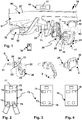
- a trailer coupling 20 of a system 10 comprises a coupling arm 21, on the free end region of which a coupling element 22, for example a coupling ball or (not shown) a plug-in receptacle or a plug-in projection for a load carrier, is arranged.
- the coupling element 22 is arranged on one end region of the coupling arm 21, and a bearing element 23 is arranged on the other end region.
- the bearing element 23 is on a vehicle side Holder 25 pivotably and / or displaceably mounted.
- the bearing element 23 is movably supported on a bearing part 26 of the holder 25.
- the coupling arm 21 In the non-use position N, the coupling arm 21 is, for example, essentially hidden behind a rear apron 93 of a motor vehicle 90 on which the trailer coupling 20 is arranged. Between the non-use position N and the use position G, the coupling arm 21 assumes several intermediate positions, of which, by way of example, in FIG Figure 3 an intermediate position Z is shown.
- the coupling arm 21 can be mounted pivotably and / or displaceably with respect to the vehicle-side holder 25, for example, about one or more axes D1, D2 or D3 drawn in as an example.
- the holder 25 is attached to a carrier 27 which extends at the rear 91 transversely to the vehicle longitudinal axis of the motor vehicle 90 or in the vehicle transverse direction.
- the coupling arm 21 can be locked in place with respect to the vehicle-side holder using a locking device 29, in particular in the use position G and / the non-use position N.
- the locking device 29 is only indicated schematically. It comprises, for example, one or more form-fit elements, form-fit contours or the like, which interlock to lock the coupling arm 21.
- the coupling arm 21 is axially displaceable with respect to the axis D1 in order to disengage the form-fitting contours and thus to be able to move the coupling arm 21 between the position of use G and the position of non-use N.
- locking with, for example, a locking bolt, balls or other form-fitting elements is also possible with the locking device 29.
- a locking drive 31 of a drive arrangement 30 is used to actuate the locking device 29, in particular in the direction of the unlocking position. It is possible for the locking device 29 to be loaded by a spring arrangement in the direction of the locking position, so that the locking drive 31 is in principle an unlocking drive.
- An actuator 32 of the drive arrangement 30 is used to actuate and adjust the coupling arm 21 between the use position G and the non-use position N.
- the drives 31, 32 include, for example, electric motors or the like.
- the drives 31, 32 are preferably provided in a housing 33 of the drive arrangement 30. It goes without saying that a drive concept with only a single drive 31 or 32 can be provided, which performs both the locking / unlocking and the adjustment of the coupling arm 21.
- a trailer socket 28 is advantageously located on the coupling arm 21.
- sensors 34, 35 are provided on the coupling arm 21, for example in the area of the trailer socket 28 or on the body of the coupling arm 21, each of which generates a sensor signal.
- the sensor 34 is, for example, a support load sensor that detects a support load that acts on the coupling arm 21.
- the sensor 35 is, for example, a rotation angle sensor which detects a rotation angle position of the trailer A relative to the motor vehicle 90.
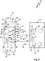
- the drive arrangement 30 can be controlled using a control device 40.
- the control device 40 is preferably arranged in an interior 92, for example in the area of a luggage compartment, of the motor vehicle 90.
- the control unit 40 is expediently hidden behind an interior lining 95 so that it is normally not accessible to the operator.
- the interior trim 95 protects the control unit 40, for example, from damage by luggage in the interior 92, for example the luggage compartment, of the motor vehicle 90.
- the control unit 40 is optimally protected from environmental influences, namely by the body of the motor vehicle 90.
- the interior cladding 95 can be permanently mounted, for example screwed, fastened by means of rivets or the like. It is also possible, however, for the interior lining 95 to have a cover 96 which can be opened or removed in order to close a receiving space for the control device 40.
- a passage opening 97 is provided on the interior cladding 95, for example the cover 96, through which the control device 40 is accessible, for example using an operating tool 98.
- the operating tool 98 is, for example, a pen, ballpoint pen or the like.
- a diameter or cross section of the passage opening 97 is not suitable for a human finger to penetrate it. Nevertheless, the control device 40 can be operated conveniently, namely on the basis of the operating device 70 explained below.
- the operating device 70 is extremely compact, its housing 72 being, for example, the size of a key fob, in particular about 2-5 cm long and about 2-3 cm wide.
- the height of the housing 72 is also kept very compact, for example less than 1 cm, preferably about 5-7 mm. Different dimensions of the operating device 70 are easily possible.
- the control device 40 and the operating device 70 communicate wirelessly with one another via a control device interface 41 and an operating device interface 72.
- the interfaces 41, 71 are radio interfaces, optical interfaces or the like.
- the frequency ranges that are preferably provided have already been explained at the beginning.
- the operating device 70 has, for example, operating elements 73, 74, in particular pushbutton switches, sensors or the like, in order to generate control commands for activating the control device 40.
- the operating device 70 can display messages from the control device 40, i.e. output message data 78, namely using display elements 75, 76, for example LEDs.
- the control device 40 can control the locking drive 31 and the actuating drive 32 via a control interface 42 and a control interface 43 of control means 55 drive.
- the control interfaces 42, 43 include power electronics suitable for this purpose.
- the control device can receive sensor signals from sensors 34 and / or 35.
- the receiving interface 44 includes, for example, corresponding electrical contacts, a wireless interface or the like.
- the control device 40 and the operating device 70 communicate with one another in a very secure manner, namely using encryption.
- a memory 45 of the control device 40 for example, a key 46 for encrypting data, for example control data 77 that the control device 70 sends to the control device 40, or message data 78 that the control device 40 sends to the control device 70, is stored.
- the memory 45 can be read out by the operating device 70 using reading means 80.
- the reading device (s) 80 can, however, only read out the memory 45 if the operating device 70 is in the immediate vicinity of the control device 40 and / or an operating element 53, which will be explained later, is operated, in particular pressed, or has been operated shortly before.
- a transmitter is assigned to the memory 52, for example. However, it is also possible for the control device 40 to send the key 46 via the wireless control device interface 41.
- the encryption means 49 of the control device 40 encrypt, for example, the reporting data 78 prior to dispatch or as part of the dispatch to the operating device 70 , are available on the display elements 75, 76 of optical output means 82 of the operating device 70.
- control device 40 and operating device 70 is preferably bidirectional, in particular bidirectionally encrypted, so that the decryption means 73 are simultaneous Encryption means and the encryption means 49 simultaneously represent or comprise decryption means.
- the processor 51 can execute programs, for example for controlling the drive arrangement 30, for realizing security functions, possibly also for encrypting or decrypting data or the like. These programs are stored in memory 52.
- a discrete construction is also conceivable, i.e. that instead of a processor 51, for example, a logic circuit is provided.
- the operating element 53 forms, so to speak, a local operating interface 54 of the control device 54.
- the operating element 53 is very difficult to reach, namely through a passage opening 57 on the housing 47 of the control device 40.
- the passage opening 57 is located on a housing cover 48 of the housing 47. It is also conceivable that the local operating interface 54 can only be reached when the housing cover 48 is open.
- the passage opening 57 of the housing 47 has a small cross section so that it can only be operated with the aid of the operating tool 98.
- An operating concept of the control device 40 can now provide that the operator opens the interior cladding 95, for example shifts the cover 46 into an open position using a bearing (not shown) or removes the cover 96 in order to access the operating element 53.
- operation using the operating tool 98 is preferably provided if emergency operation is necessary.
- the operator can then, for example, actuate the trailer coupling 20 by means of a keystroke sequence or simply actuate the operating element 53, for example unlock the locking device 29 using the locking drive 31 and / or adjust the coupling arm 21 using the actuating drive 32 between the use position G and the non-use position N.
- the operator can use the controls 73, 74, for example, to actuate the trailer coupling 20 in the direction of the non-use position N or the use position G and / or unlock or lock the trailer coupling 20 or both.
- a complex laying of cables between the operating device 70 and the control device 40 is not necessary.
- the operating device 40 does not have to be so accessible in the interior of the motor vehicle 90 that its local operating interface 54 is easily accessible.
- the trailer coupling 20 and the control unit 40 signal the correct function. If, for example, the display element 75 lights up (this is the case in the intermediate position Z), the trailer coupling is unsafe, ie unlocked and / or outside of the position of use or non-use position. However, it lights up as in the Figures 2 and 4 shown in the use position G or the non-use position. Correct locking of the trailer coupling 20 is signaled in the display element 76.
- the control device 40 advantageously has a receiving interface 59, for example a bus interface, for receiving status data of the motor vehicle 90.
- the status data contain, for example, information about whether at least one door or a luggage compartment lid of the motor vehicle 90 is open, whether the ignition key is in the ignition lock, whether the motor vehicle 90 is driving or not, or the like. These conditions form so-called activation conditions. If, namely, a non-safe state is present, that is to say, for example, the motor vehicle 90 is driving, the control device 40 blocks the actuation of the drive arrangement 30, even if it is operated by the operating device 70 corresponding control commands or control data 77 are sent. However, when the motor vehicle is stationary and, for example, at least one door is open, commands for controlling the trailer coupling 20 or the control device 40 can be given via the operating device 70.
- An additional safety function is that acoustic output means 58 of the control device 40 signal through a tone sequence, a continuous tone or the like that the trailer coupling 20 is outside the use position G or the non-use position N and / or is not locked, i.e. is unsafe.
- a preferred embodiment of the invention provides that in the operating device 70 or any other operating device according to the invention, a feedback occurs when one or both of the operating elements 73, 74 are actuated. Then, for example, the display elements 75 and / or 76, in any case optical output means or acoustic output means of a respective operating device, show that an operating element of the operating device is actuated to actuate the trailer coupling.
Landscapes
- Engineering & Computer Science (AREA)
- Transportation (AREA)
- Mechanical Engineering (AREA)
- Lock And Its Accessories (AREA)
- Small-Scale Networks (AREA)
Claims (15)
- Système comprenant un appareil de commande (40) pour un attelage de remorque (20) disposé ou pouvant être disposé sur un véhicule à moteur (90), qui présente un élément de couplage (22) disposé sur un bras d'attelage (21) pour accoupler une remorque, et un appareil d'utilisation (70) mobile séparé du véhicule à moteur (90) et de l'appareil de commande (40), dans lequel l'appareil de commande (40) présente des moyens de commande (55) pour commander au moins une fonction de l'attelage de remorque (20) et/ou des moyens d'évaluation (56) pour évaluer au moins un signal de capteur d'un capteur (34, 35) associé à l'attelage de remorque (20), dans lequel l'appareil de commande (40) présente une interface d'appareil d'utilisation (71) pour la communication sans fil avec une interface d'appareil de commande (41) de l'appareil d'utilisation mobile (70), et dans lequel l'appareil d'utilisation (70) est configuré pour envoyer au moins un signal de commande pour piloter les moyens de commande (55) de l'appareil de commande (40) et/ou pour émettre au moins un signal de capteur du capteur (34, 35), caractérisé en ce que l'interface d'appareil d'utilisation (71) et l'interface d'appareil de commande (41) présentent des moyens de cryptage (49) et des moyens de décryptage (79) pour une communication cryptée entre elles, que l'appareil d'utilisation (70) et/ou l'appareil de commande (40) présentent au moins un moyen de lecture (80) pour lire une clé (46) pour les moyens de cryptage (49) et les moyens de décryptage (79) pour la communication cryptée, et que l'au moins un moyen de lecture (80) présente une interface sans fil, à savoir une interface radio, pour lire sans fil la clé, en particulier pour lire la clé (46) par l'intermédiaire d'une étiquette RFID, et/ou une interface optique pour lire la clé (46) à l'aide d'un code optique, en particulier d'un code à barres ou d'un QR code.
- Système selon la revendication 1, caractérisé en ce que les moyens de cryptage (49) et les moyens de décryptage (79) fournissent un codage à 32 bits et/ou 16 bits, et/ou que les moyens de cryptage (49) sont configurés pour un cryptage à l'aide d'un procédé de roulement ou d'un procédé avec un code à changement aléatoire et/ou cyclique.
- Système selon la revendication 1 ou 2, caractérisé en ce qu'une clé (46) pour les moyens de cryptage (49) de l'appareil d'utilisation et/ou de l'appareil de commande (40) est mémorisée sur l'appareil de commande (40) ou dans l'appareil de commande (40).
- Système selon l'une quelconque des revendications précédentes, caractérisé en ce que l'au moins un moyen de lecture (80) est configuré pour lire la clé (46) sur une courte distance de 2 mètres au maximum, de préférence de 1,5 mètre au maximum, de manière opportune de 60 à 30 cm au maximum, par rapport à la mémoire, dans laquelle la clé (46) est mémorisée.
- Système selon l'une quelconque des revendications précédentes, caractérisé en ce que la mémoire avec la clé (46) est protégée par rapport à l'extérieur par un écran de protection, en particulier une tôle de carrosserie ou un composant de l'appareil de commande (40).
- Système selon l'une quelconque des revendications précédentes, caractérisé en ce qu'une mémoire pour une clé (46) est disposée à bord de l'appareil de commande (40) pour la communication entre l'appareil d'utilisation (70) et l'appareil de commande (40), dans lequel la mémoire peut être lue par l'appareil d'utilisation (70) exclusivement de manière filaire en cas de contact direct de l'appareil d'utilisation (70) avec l'appareil de commande (40) et/ou lors de l'actionnement d'un capteur ou d'un commutateur à bord de l'appareil de commande (40) et/ou l'appareil de commande (40) présente un dispositif d'envoi pour envoyer la clé (46) à l'appareil d'utilisation (70), qui peut être actionné en particulier manuellement par un utilisateur.
- Système selon l'une quelconque des revendications précédentes, caractérisé en ce que l'appareil de commande (40) présente une interface d'utilisation (54) pour l'utilisation locale, dans lequel l'interface d'utilisation (54) peut être utilisée seulement à l'aide d'un outil d'utilisation (98), par exemple d'un stylet et/ou est recouvert par un recouvrement, qui peut être ajusté entre une position ouverte, dans laquelle l'interface d'utilisation (54) est accessible à un utilisateur, et une position fermée, dans laquelle le recouvrement ferme l'interface d'utilisation (54) la rendant inaccessible à un utilisateur.
- Système selon la revendication 7, caractérisé en ce que l'interface d'utilisation (54) locale de l'appareil de commande (40) comprend un commutateur ou capteur électrique disposé sur une platine de commande (50) ou est formée par celui-ci et/ou n'a aucun élément d'utilisation pouvant être utilisé directement sans un outil par un utilisateur, et/ou que l'interface d'utilisation (54) locale de l'appareil de commande (40) ne comprend aucun moyen d'émission (58) optique et/ou acoustique, en particulier aucun moyen d'affichage, et/ou que l'interface d'utilisation (54) locale est configurée pour déclencher un envoi d'une clé (46) pour une communication cryptée entre l'appareil de commande (40) et l'appareil d'utilisation (70), et/ou qu'un commutateur ou capteur électrique de l'interface d'utilisation (54) locale de l'appareil de commande (40) est disposé dans un espace intérieur d'un boîtier (47) de l'appareil de commande (40), dans lequel le boîtier (47) présente une ouverture de passage (57) pour l'outil d'utilisation (98), à travers laquelle le capteur ou commutateur peut être utilisé, et/ou le recouvrement est formé par un couvercle de boîtier (48) d'un boîtier (47) de l'appareil de commande (40) ou comprend un couvercle de boîtier (48), et/ou que le recouvrement comprend une partie d'habillage d'un habillage d'espace intérieur du véhicule à moteur (90) ou est formé par celle-ci.
- Système selon l'une quelconque des revendications précédentes, caractérisé en ce que sont prévus sur en particulier exclusivement l'appareil d'utilisation (70) des moyens d'émission optiques pour afficher une fonction des moyens de commande (55), en particulier un verrouillage ou déverrouillage du bras d'attelage (21) et/ou un ajustement du bras d'attelage (21) entre une position de non-utilisation (N) et une position d'utilisation (G) et/ou pour émettre l'au moins un signal de capteur, dans lequel les moyens d'émission optiques de l'appareil d'utilisation (70) comprennent avantageusement exclusivement des DEL ou des moyens d'émission configurés pour émettre des signaux optiques simples sous la forme de séquences lumineuses et/ou de couleurs d'éclairage.
- Système selon l'une quelconque des revendications précédentes, caractérisé en ce que l'appareil de commande (40) ou une interface d'utilisation (81) de l'appareil de commande (70) présente un concept d'utilisation de sécurité, où pour déclencher une fonction des moyens de commande (55) de l'appareil de commande (40), au moins deux éléments d'utilisation (73, 74) doivent être actionnés simultanément ou selon un ordre défini et/ou au moins un élément d'utilisation (73, 74) doit être utilisé dans un ordre défini.
- Système selon l'une quelconque des revendications précédentes, caractérisé en ce que les moyens de commande (55) sont configurés pour piloter au moins un entraînement, en particulier pour verrouiller ou déverrouiller le bras d'attelage (21) et/ou pour ajuster le bras d'attelage (21) entre une position d'utilisation (G) et une position de non-utilisation, et/ou qu'il comprend l'attelage de remorque (20).
- Système selon l'une quelconque des revendications précédentes, caractérisé en ce que l'interface d'appareil de commande (41) et l'interface d'appareil d'utilisation (71) sont configurées pour une communication radio, en particulier à au moins 1 GHz, de préférence au moins 2 GHz, en particulier 2,4 Ghz et/ou la communication radio se limite à une zone proche de 15 m au maximum, en particulier de 10 m au maximum, de manière particulièrement préférée de 5 m au maximum.
- Système selon l'une quelconque des revendications précédentes, caractérisé en ce que l'appareil d'utilisation (70) présente un boîtier (72) de la taille d'un porte-clés ou est intégré dans un porte-clés et/ou fait partie intégrante d'une clé de véhicule.
- Système selon l'une quelconque des revendications précédentes, caractérisé en ce que l'appareil de commande (40) présente des moyens d'émission acoustiques pour émettre de manière acoustique une fonction, pouvant être pilotée par l'appareil d'utilisation mobile (70), de l'appareil de commande (40), et/ou que l'appareil de commande (40) comprend une entrée pour recevoir au moins une condition d'activation, dans lequel les moyens de commande (55) remplissent l'au moins une fonction de l'attelage de remorque (20) et/ou l'évaluation de l'au moins un signal de capteur en fonction de l'au moins une condition d'activation.
- Système selon l'une quelconque des revendications précédentes, caractérisé en ce que les moyens de commande (55) sont configurés ou prévus pour commander un verrouillage et/ou un déverrouillage de l'attelage de remorque et/ou un ajustement du bras d'attelage (21) entre une position d'utilisation adaptée pour tirer une remorque et une position de non-utilisation, où le bras d'attelage est disposé en particulier davantage à proximité d'une carrosserie du véhicule à moteur (90), et/ou les moyens d'évaluation sont configurés pour évaluer au moins un signal de capteur de charge d'un capteur de charge disposé sur l'attelage de remorque, en particulier l'élément de support ou le bras d'attelage (21) de l'attelage de remorque ou un signal d'angle d'un capteur d'angle, dans lequel le capteur d'angle est configuré ou prévu pour détecter un angle relatif entre l'attelage de remorque et une remorque accouplée à l'attelage de remorque.
Applications Claiming Priority (2)
| Application Number | Priority Date | Filing Date | Title |
|---|---|---|---|
| DE102015105253 | 2015-04-07 | ||
| DE102015108526.7A DE102015108526A1 (de) | 2015-04-07 | 2015-05-29 | System mit einem Steuergerät und einem Bediengerät |
Publications (3)
| Publication Number | Publication Date |
|---|---|
| EP3078514A2 EP3078514A2 (fr) | 2016-10-12 |
| EP3078514A3 EP3078514A3 (fr) | 2016-10-26 |
| EP3078514B1 true EP3078514B1 (fr) | 2021-09-01 |
Family
ID=55646495
Family Applications (1)
| Application Number | Title | Priority Date | Filing Date |
|---|---|---|---|
| EP16163543.8A Active EP3078514B1 (fr) | 2015-04-07 | 2016-04-01 | Système comprenant un appareil de commande et un dispositif de commande |
Country Status (1)
| Country | Link |
|---|---|
| EP (1) | EP3078514B1 (fr) |
Family Cites Families (3)
| Publication number | Priority date | Publication date | Assignee | Title |
|---|---|---|---|---|
| WO1994018036A1 (fr) * | 1993-02-12 | 1994-08-18 | Robert Bosch Gmbh | Installation telecommandee pour la mise en securite d'un vehicule |
| US20080303647A1 (en) * | 2007-06-06 | 2008-12-11 | Andre Pare | Accessory for a locking assembly |
| DE102011120651A1 (de) | 2011-12-09 | 2013-06-13 | Westfalia-Automotive Gmbh | Steuergerät und Anhängekupplung zur Kommunikation mit einem Bediengerät |
-
2016
- 2016-04-01 EP EP16163543.8A patent/EP3078514B1/fr active Active
Also Published As
| Publication number | Publication date |
|---|---|
| EP3078514A2 (fr) | 2016-10-12 |
| EP3078514A3 (fr) | 2016-10-26 |
Similar Documents
| Publication | Publication Date | Title |
|---|---|---|
| DE10259081B4 (de) | Universelles Garagentoröffnungssystem und -verfahren | |
| EP0440974B2 (fr) | Système de sécurité pour véhicules à moteur | |
| DE102017123254B4 (de) | Fahrzeugsteuersystem | |
| DE102011056497B4 (de) | Verfahren zum Bereitstellen von einer Fahrzeugkommunikation | |
| EP3536524B1 (fr) | Appareil de commande, barre d'attelage et étrier de guidage permettant la communication avec un appareil de commande | |
| DE102005059061B4 (de) | Verfahren und Vorrichtung zum Öffnen eines Fahrzeugs | |
| EP3501916B1 (fr) | Procédé de fonctionnement d'un système de surveillance radio d'un véhicule automobile ainsi que système de surveillance et répondeur pour le système de surveillance | |
| DE102007035069A1 (de) | Verfahren und Vorrichtung zum Nutzen eines Senders mit einer Bereichsbegrenzung, um eine bewegliche Barrierenbedienvorrichtung zu steuern | |
| EP3434850B1 (fr) | Serrure électronique pour deux roues | |
| DE202016102327U1 (de) | Gerät zur Verhinderung des Missbrauchs eines Funkschlüssels | |
| DE102016110025A1 (de) | Abgeschirmtes Datenübertragungssystem | |
| EP3504688A1 (fr) | Dispositif de fermeture à clé radio pour un véhicule automobile, véhicule automobile et procédé permettant de faire fonctionner le dispositif de fermeture | |
| DE102013226840B4 (de) | Drahtlose Zugangsvorrichtung für ein Fahrzeug, insbesondere ein Kraftfahrzeug | |
| DE102015103329A1 (de) | Vorrichtung zum Betätigen eines Signalgebers | |
| DE102014202713A1 (de) | Vorrichtung zur Berechtigungsprüfung eines Anwenders gegenüber einem Fortbewegungsmittel | |
| EP3064404B1 (fr) | Interruption fonctionnelle d'un systeme d'acces de vehicule | |
| EP3595942A1 (fr) | Arrangement et système d'authentification pour un véhicule automobile | |
| DE102015108526A1 (de) | System mit einem Steuergerät und einem Bediengerät | |
| DE102015212129B4 (de) | Tür für ein öffentliches Verkehrsmittel mit berührungslosem Schalter | |
| EP3078514B1 (fr) | Système comprenant un appareil de commande et un dispositif de commande | |
| DE102018200770A1 (de) | Verfahren zur Übergabe der Fahrzeugkontrolle an einen Fahrer im Anschluss an einen ferngesteuerten Ausparkvorgang | |
| DE10160964A1 (de) | Verfahren und Vorrichtung zum Diebstahlschutz von Kraftfahrzeugen | |
| DE102016008164B4 (de) | Vorrichtung zum Schutz eines schlüssellosen Zugangssystems für ein Kraftfahrzeug gegen Relaisangriffe | |
| DE102006008146A1 (de) | Mobiler Identifikationsgeber | |
| EP2125451B1 (fr) | Dispositif d'identification mobile d'un systeme de securite |
Legal Events
| Date | Code | Title | Description |
|---|---|---|---|
| PUAI | Public reference made under article 153(3) epc to a published international application that has entered the european phase |
Free format text: ORIGINAL CODE: 0009012 |
|
| PUAL | Search report despatched |
Free format text: ORIGINAL CODE: 0009013 |
|
| AK | Designated contracting states |
Kind code of ref document: A2 Designated state(s): AL AT BE BG CH CY CZ DE DK EE ES FI FR GB GR HR HU IE IS IT LI LT LU LV MC MK MT NL NO PL PT RO RS SE SI SK SM TR |
|
| AX | Request for extension of the european patent |
Extension state: BA ME |
|
| AK | Designated contracting states |
Kind code of ref document: A3 Designated state(s): AL AT BE BG CH CY CZ DE DK EE ES FI FR GB GR HR HU IE IS IT LI LT LU LV MC MK MT NL NO PL PT RO RS SE SI SK SM TR |
|
| AX | Request for extension of the european patent |
Extension state: BA ME |
|
| RIC1 | Information provided on ipc code assigned before grant |
Ipc: B60D 1/62 20060101ALI20160922BHEP Ipc: B60D 1/06 20060101ALI20160922BHEP Ipc: B60D 1/26 20060101AFI20160922BHEP Ipc: B60D 1/54 20060101ALI20160922BHEP |
|
| STAA | Information on the status of an ep patent application or granted ep patent |
Free format text: STATUS: REQUEST FOR EXAMINATION WAS MADE |
|
| 17P | Request for examination filed |
Effective date: 20170411 |
|
| RBV | Designated contracting states (corrected) |
Designated state(s): AL AT BE BG CH CY CZ DE DK EE ES FI FR GB GR HR HU IE IS IT LI LT LU LV MC MK MT NL NO PL PT RO RS SE SI SK SM TR |
|
| STAA | Information on the status of an ep patent application or granted ep patent |
Free format text: STATUS: EXAMINATION IS IN PROGRESS |
|
| 17Q | First examination report despatched |
Effective date: 20190405 |
|
| GRAP | Despatch of communication of intention to grant a patent |
Free format text: ORIGINAL CODE: EPIDOSNIGR1 |
|
| STAA | Information on the status of an ep patent application or granted ep patent |
Free format text: STATUS: GRANT OF PATENT IS INTENDED |
|
| INTG | Intention to grant announced |
Effective date: 20210525 |
|
| RIN1 | Information on inventor provided before grant (corrected) |
Inventor name: PASCHER, NIKOLAS Inventor name: KRANZ, TORSTEN Inventor name: BEUTIN, JOERG |
|
| GRAS | Grant fee paid |
Free format text: ORIGINAL CODE: EPIDOSNIGR3 |
|
| GRAA | (expected) grant |
Free format text: ORIGINAL CODE: 0009210 |
|
| STAA | Information on the status of an ep patent application or granted ep patent |
Free format text: STATUS: THE PATENT HAS BEEN GRANTED |
|
| AK | Designated contracting states |
Kind code of ref document: B1 Designated state(s): AL AT BE BG CH CY CZ DE DK EE ES FI FR GB GR HR HU IE IS IT LI LT LU LV MC MK MT NL NO PL PT RO RS SE SI SK SM TR |
|
| REG | Reference to a national code |
Ref country code: GB Ref legal event code: FG4D Free format text: NOT ENGLISH |
|
| REG | Reference to a national code |
Ref country code: CH Ref legal event code: EP Ref country code: AT Ref legal event code: REF Ref document number: 1425849 Country of ref document: AT Kind code of ref document: T Effective date: 20210915 |
|
| REG | Reference to a national code |
Ref country code: DE Ref legal event code: R096 Ref document number: 502016013732 Country of ref document: DE |
|
| REG | Reference to a national code |
Ref country code: IE Ref legal event code: FG4D Free format text: LANGUAGE OF EP DOCUMENT: GERMAN |
|
| REG | Reference to a national code |
Ref country code: LT Ref legal event code: MG9D |
|
| REG | Reference to a national code |
Ref country code: NL Ref legal event code: MP Effective date: 20210901 |
|
| PG25 | Lapsed in a contracting state [announced via postgrant information from national office to epo] |
Ref country code: BG Free format text: LAPSE BECAUSE OF FAILURE TO SUBMIT A TRANSLATION OF THE DESCRIPTION OR TO PAY THE FEE WITHIN THE PRESCRIBED TIME-LIMIT Effective date: 20211201 Ref country code: LT Free format text: LAPSE BECAUSE OF FAILURE TO SUBMIT A TRANSLATION OF THE DESCRIPTION OR TO PAY THE FEE WITHIN THE PRESCRIBED TIME-LIMIT Effective date: 20210901 Ref country code: ES Free format text: LAPSE BECAUSE OF FAILURE TO SUBMIT A TRANSLATION OF THE DESCRIPTION OR TO PAY THE FEE WITHIN THE PRESCRIBED TIME-LIMIT Effective date: 20210901 Ref country code: FI Free format text: LAPSE BECAUSE OF FAILURE TO SUBMIT A TRANSLATION OF THE DESCRIPTION OR TO PAY THE FEE WITHIN THE PRESCRIBED TIME-LIMIT Effective date: 20210901 Ref country code: NO Free format text: LAPSE BECAUSE OF FAILURE TO SUBMIT A TRANSLATION OF THE DESCRIPTION OR TO PAY THE FEE WITHIN THE PRESCRIBED TIME-LIMIT Effective date: 20211201 Ref country code: HR Free format text: LAPSE BECAUSE OF FAILURE TO SUBMIT A TRANSLATION OF THE DESCRIPTION OR TO PAY THE FEE WITHIN THE PRESCRIBED TIME-LIMIT Effective date: 20210901 Ref country code: RS Free format text: LAPSE BECAUSE OF FAILURE TO SUBMIT A TRANSLATION OF THE DESCRIPTION OR TO PAY THE FEE WITHIN THE PRESCRIBED TIME-LIMIT Effective date: 20210901 Ref country code: SE Free format text: LAPSE BECAUSE OF FAILURE TO SUBMIT A TRANSLATION OF THE DESCRIPTION OR TO PAY THE FEE WITHIN THE PRESCRIBED TIME-LIMIT Effective date: 20210901 |
|
| PG25 | Lapsed in a contracting state [announced via postgrant information from national office to epo] |
Ref country code: PL Free format text: LAPSE BECAUSE OF FAILURE TO SUBMIT A TRANSLATION OF THE DESCRIPTION OR TO PAY THE FEE WITHIN THE PRESCRIBED TIME-LIMIT Effective date: 20210901 Ref country code: LV Free format text: LAPSE BECAUSE OF FAILURE TO SUBMIT A TRANSLATION OF THE DESCRIPTION OR TO PAY THE FEE WITHIN THE PRESCRIBED TIME-LIMIT Effective date: 20210901 Ref country code: GR Free format text: LAPSE BECAUSE OF FAILURE TO SUBMIT A TRANSLATION OF THE DESCRIPTION OR TO PAY THE FEE WITHIN THE PRESCRIBED TIME-LIMIT Effective date: 20211202 |
|
| PG25 | Lapsed in a contracting state [announced via postgrant information from national office to epo] |
Ref country code: IS Free format text: LAPSE BECAUSE OF FAILURE TO SUBMIT A TRANSLATION OF THE DESCRIPTION OR TO PAY THE FEE WITHIN THE PRESCRIBED TIME-LIMIT Effective date: 20220101 Ref country code: SM Free format text: LAPSE BECAUSE OF FAILURE TO SUBMIT A TRANSLATION OF THE DESCRIPTION OR TO PAY THE FEE WITHIN THE PRESCRIBED TIME-LIMIT Effective date: 20210901 Ref country code: SK Free format text: LAPSE BECAUSE OF FAILURE TO SUBMIT A TRANSLATION OF THE DESCRIPTION OR TO PAY THE FEE WITHIN THE PRESCRIBED TIME-LIMIT Effective date: 20210901 Ref country code: RO Free format text: LAPSE BECAUSE OF FAILURE TO SUBMIT A TRANSLATION OF THE DESCRIPTION OR TO PAY THE FEE WITHIN THE PRESCRIBED TIME-LIMIT Effective date: 20210901 Ref country code: PT Free format text: LAPSE BECAUSE OF FAILURE TO SUBMIT A TRANSLATION OF THE DESCRIPTION OR TO PAY THE FEE WITHIN THE PRESCRIBED TIME-LIMIT Effective date: 20220103 Ref country code: NL Free format text: LAPSE BECAUSE OF FAILURE TO SUBMIT A TRANSLATION OF THE DESCRIPTION OR TO PAY THE FEE WITHIN THE PRESCRIBED TIME-LIMIT Effective date: 20210901 Ref country code: EE Free format text: LAPSE BECAUSE OF FAILURE TO SUBMIT A TRANSLATION OF THE DESCRIPTION OR TO PAY THE FEE WITHIN THE PRESCRIBED TIME-LIMIT Effective date: 20210901 Ref country code: CZ Free format text: LAPSE BECAUSE OF FAILURE TO SUBMIT A TRANSLATION OF THE DESCRIPTION OR TO PAY THE FEE WITHIN THE PRESCRIBED TIME-LIMIT Effective date: 20210901 Ref country code: AL Free format text: LAPSE BECAUSE OF FAILURE TO SUBMIT A TRANSLATION OF THE DESCRIPTION OR TO PAY THE FEE WITHIN THE PRESCRIBED TIME-LIMIT Effective date: 20210901 |
|
| REG | Reference to a national code |
Ref country code: DE Ref legal event code: R097 Ref document number: 502016013732 Country of ref document: DE |
|
| PLBE | No opposition filed within time limit |
Free format text: ORIGINAL CODE: 0009261 |
|
| STAA | Information on the status of an ep patent application or granted ep patent |
Free format text: STATUS: NO OPPOSITION FILED WITHIN TIME LIMIT |
|
| PG25 | Lapsed in a contracting state [announced via postgrant information from national office to epo] |
Ref country code: IT Free format text: LAPSE BECAUSE OF FAILURE TO SUBMIT A TRANSLATION OF THE DESCRIPTION OR TO PAY THE FEE WITHIN THE PRESCRIBED TIME-LIMIT Effective date: 20210901 Ref country code: DK Free format text: LAPSE BECAUSE OF FAILURE TO SUBMIT A TRANSLATION OF THE DESCRIPTION OR TO PAY THE FEE WITHIN THE PRESCRIBED TIME-LIMIT Effective date: 20210901 |
|
| 26N | No opposition filed |
Effective date: 20220602 |
|
| PG25 | Lapsed in a contracting state [announced via postgrant information from national office to epo] |
Ref country code: SI Free format text: LAPSE BECAUSE OF FAILURE TO SUBMIT A TRANSLATION OF THE DESCRIPTION OR TO PAY THE FEE WITHIN THE PRESCRIBED TIME-LIMIT Effective date: 20210901 |
|
| REG | Reference to a national code |
Ref country code: CH Ref legal event code: PL |
|
| GBPC | Gb: european patent ceased through non-payment of renewal fee |
Effective date: 20220401 |
|
| REG | Reference to a national code |
Ref country code: BE Ref legal event code: MM Effective date: 20220430 |
|
| PG25 | Lapsed in a contracting state [announced via postgrant information from national office to epo] |
Ref country code: MC Free format text: LAPSE BECAUSE OF FAILURE TO SUBMIT A TRANSLATION OF THE DESCRIPTION OR TO PAY THE FEE WITHIN THE PRESCRIBED TIME-LIMIT Effective date: 20210901 Ref country code: LU Free format text: LAPSE BECAUSE OF NON-PAYMENT OF DUE FEES Effective date: 20220401 Ref country code: LI Free format text: LAPSE BECAUSE OF NON-PAYMENT OF DUE FEES Effective date: 20220430 Ref country code: GB Free format text: LAPSE BECAUSE OF NON-PAYMENT OF DUE FEES Effective date: 20220401 Ref country code: CH Free format text: LAPSE BECAUSE OF NON-PAYMENT OF DUE FEES Effective date: 20220430 |
|
| PG25 | Lapsed in a contracting state [announced via postgrant information from national office to epo] |
Ref country code: BE Free format text: LAPSE BECAUSE OF NON-PAYMENT OF DUE FEES Effective date: 20220430 |
|
| PG25 | Lapsed in a contracting state [announced via postgrant information from national office to epo] |
Ref country code: IE Free format text: LAPSE BECAUSE OF NON-PAYMENT OF DUE FEES Effective date: 20220401 |
|
| REG | Reference to a national code |
Ref country code: AT Ref legal event code: MM01 Ref document number: 1425849 Country of ref document: AT Kind code of ref document: T Effective date: 20220401 |
|
| PG25 | Lapsed in a contracting state [announced via postgrant information from national office to epo] |
Ref country code: AT Free format text: LAPSE BECAUSE OF NON-PAYMENT OF DUE FEES Effective date: 20220401 |
|
| PG25 | Lapsed in a contracting state [announced via postgrant information from national office to epo] |
Ref country code: HU Free format text: LAPSE BECAUSE OF FAILURE TO SUBMIT A TRANSLATION OF THE DESCRIPTION OR TO PAY THE FEE WITHIN THE PRESCRIBED TIME-LIMIT; INVALID AB INITIO Effective date: 20160401 |
|
| PG25 | Lapsed in a contracting state [announced via postgrant information from national office to epo] |
Ref country code: MK Free format text: LAPSE BECAUSE OF FAILURE TO SUBMIT A TRANSLATION OF THE DESCRIPTION OR TO PAY THE FEE WITHIN THE PRESCRIBED TIME-LIMIT Effective date: 20210901 Ref country code: CY Free format text: LAPSE BECAUSE OF FAILURE TO SUBMIT A TRANSLATION OF THE DESCRIPTION OR TO PAY THE FEE WITHIN THE PRESCRIBED TIME-LIMIT Effective date: 20210901 |
|
| PG25 | Lapsed in a contracting state [announced via postgrant information from national office to epo] |
Ref country code: TR Free format text: LAPSE BECAUSE OF FAILURE TO SUBMIT A TRANSLATION OF THE DESCRIPTION OR TO PAY THE FEE WITHIN THE PRESCRIBED TIME-LIMIT Effective date: 20210901 |
|
| PG25 | Lapsed in a contracting state [announced via postgrant information from national office to epo] |
Ref country code: MT Free format text: LAPSE BECAUSE OF FAILURE TO SUBMIT A TRANSLATION OF THE DESCRIPTION OR TO PAY THE FEE WITHIN THE PRESCRIBED TIME-LIMIT Effective date: 20210901 |
|
| PGFP | Annual fee paid to national office [announced via postgrant information from national office to epo] |
Ref country code: DE Payment date: 20250429 Year of fee payment: 10 |
|
| PGFP | Annual fee paid to national office [announced via postgrant information from national office to epo] |
Ref country code: FR Payment date: 20260324 Year of fee payment: 11 |