EP3078529A2 - Vorrichtung zur montage eines gastanks eines fahrzeugs und gastankanordnung damit - Google Patents
Vorrichtung zur montage eines gastanks eines fahrzeugs und gastankanordnung damit Download PDFInfo
- Publication number
- EP3078529A2 EP3078529A2 EP16163617.0A EP16163617A EP3078529A2 EP 3078529 A2 EP3078529 A2 EP 3078529A2 EP 16163617 A EP16163617 A EP 16163617A EP 3078529 A2 EP3078529 A2 EP 3078529A2
- Authority
- EP
- European Patent Office
- Prior art keywords
- gas
- frames
- gas tank
- tanks
- pressure reducing
- Prior art date
- Legal status (The legal status is an assumption and is not a legal conclusion. Google has not performed a legal analysis and makes no representation as to the accuracy of the status listed.)
- Withdrawn
Links
- 239000007789 gas Substances 0.000 description 124
- 239000000446 fuel Substances 0.000 description 15
- 239000002184 metal Substances 0.000 description 7
- VNWKTOKETHGBQD-UHFFFAOYSA-N methane Chemical compound C VNWKTOKETHGBQD-UHFFFAOYSA-N 0.000 description 4
- 238000007599 discharging Methods 0.000 description 3
- 238000000034 method Methods 0.000 description 3
- 239000000356 contaminant Substances 0.000 description 2
- 239000003949 liquefied natural gas Substances 0.000 description 2
- 239000000463 material Substances 0.000 description 2
- 239000003345 natural gas Substances 0.000 description 2
- 230000003014 reinforcing effect Effects 0.000 description 2
- 229920002430 Fibre-reinforced plastic Polymers 0.000 description 1
- 239000003034 coal gas Substances 0.000 description 1
- 230000008878 coupling Effects 0.000 description 1
- 238000010168 coupling process Methods 0.000 description 1
- 238000005859 coupling reaction Methods 0.000 description 1
- 239000011151 fibre-reinforced plastic Substances 0.000 description 1
- 239000002737 fuel gas Substances 0.000 description 1
- 239000003502 gasoline Substances 0.000 description 1
- 238000002347 injection Methods 0.000 description 1
- 239000007924 injection Substances 0.000 description 1
- 239000003921 oil Substances 0.000 description 1
- 239000003129 oil well Substances 0.000 description 1
- 239000000126 substance Substances 0.000 description 1
Images


Classifications
-
- B—PERFORMING OPERATIONS; TRANSPORTING
- B60—VEHICLES IN GENERAL
- B60K—ARRANGEMENT OR MOUNTING OF PROPULSION UNITS OR OF TRANSMISSIONS IN VEHICLES; ARRANGEMENT OR MOUNTING OF PLURAL DIVERSE PRIME-MOVERS IN VEHICLES; AUXILIARY DRIVES FOR VEHICLES; INSTRUMENTATION OR DASHBOARDS FOR VEHICLES; ARRANGEMENTS IN CONNECTION WITH COOLING, AIR INTAKE, GAS EXHAUST OR FUEL SUPPLY OF PROPULSION UNITS IN VEHICLES
- B60K15/00—Arrangement in connection with fuel supply of combustion engines or other fuel consuming energy converters, e.g. fuel cells; Mounting or construction of fuel tanks
- B60K15/03—Fuel tanks
- B60K15/063—Arrangement of tanks
- B60K15/067—Mounting of tanks
- B60K15/07—Mounting of tanks of gas tanks
-
- B—PERFORMING OPERATIONS; TRANSPORTING
- B60—VEHICLES IN GENERAL
- B60K—ARRANGEMENT OR MOUNTING OF PROPULSION UNITS OR OF TRANSMISSIONS IN VEHICLES; ARRANGEMENT OR MOUNTING OF PLURAL DIVERSE PRIME-MOVERS IN VEHICLES; AUXILIARY DRIVES FOR VEHICLES; INSTRUMENTATION OR DASHBOARDS FOR VEHICLES; ARRANGEMENTS IN CONNECTION WITH COOLING, AIR INTAKE, GAS EXHAUST OR FUEL SUPPLY OF PROPULSION UNITS IN VEHICLES
- B60K15/00—Arrangement in connection with fuel supply of combustion engines or other fuel consuming energy converters, e.g. fuel cells; Mounting or construction of fuel tanks
- B60K15/01—Arrangement of fuel conduits
- B60K15/013—Arrangement of fuel conduits of gas conduits
-
- B—PERFORMING OPERATIONS; TRANSPORTING
- B60—VEHICLES IN GENERAL
- B60K—ARRANGEMENT OR MOUNTING OF PROPULSION UNITS OR OF TRANSMISSIONS IN VEHICLES; ARRANGEMENT OR MOUNTING OF PLURAL DIVERSE PRIME-MOVERS IN VEHICLES; AUXILIARY DRIVES FOR VEHICLES; INSTRUMENTATION OR DASHBOARDS FOR VEHICLES; ARRANGEMENTS IN CONNECTION WITH COOLING, AIR INTAKE, GAS EXHAUST OR FUEL SUPPLY OF PROPULSION UNITS IN VEHICLES
- B60K15/00—Arrangement in connection with fuel supply of combustion engines or other fuel consuming energy converters, e.g. fuel cells; Mounting or construction of fuel tanks
- B60K15/03—Fuel tanks
- B60K2015/03118—Multiple tanks, i.e. two or more separate tanks
- B60K2015/03144—Fluid connections between the tanks
Definitions
- the present invention relates to an apparatus for mounting a gas tank and a gas tank assembly using the same, and more particularly, to an apparatus for mounting a gas tank for storing fuel gas, such as Liquefied Natural Gas (LNG), to a vehicle.
- fuel gas such as Liquefied Natural Gas (LNG)
- CNG Compressed Natural Gas
- gas such as natural gas, coal gas, oil gas, oil well gas, and coalpit gas, are compressed at 200 atmospheric pressure or more, and the gas in a liquefied state is used.
- the CNG In a case of the CNG, a degree of discharge of the contaminant material is considerably low compared to the fuel in the related art, and the CNG may be used without a great change in an existing engine of a vehicle.
- the CNG is used in a compressed state at a high pressure as described above, so that a means for safely storing the CNG and stably supplying fuel to a fuel supply system is required.
- a gas tank endurable to a high pressure and a pressure reducing valve for reducing pressure of high-pressure compressed gas and supplying the pressure-reduced compressed gas from the gas tank to the fuel supply system are required.
- the gas tank having a special structure, which is capable of stably storing gas from impact applied during an operation of a vehicle has been used.
- An example of the gas tank is disclosed in "Korean Utility Model No. 1996-0005988 ".
- a pressure relief device is mounted to the pressure reducing valve.
- An example of the gas tank provided with the PRD is illustrated in FIGs. 1 and 2 .
- a pressure reducing valve 3 for supplying and discharging fuel is mounted to the gas tank 1, and a PRD 10 is mounted to the pressure reducing valve 3.
- the PRD 10 is installed between a tank connection path 3a and an external-side connection path 3b provided at the pressure reducing valve 3 as illustrated in FIG. 2 , and includes a piston 11, a spring 13, and a fusible metal 15 well-melted in heat.
- the fusible metal 15 ordinarily restricts a movement of the piston 11, and when a temperature of the pressure reducing valve 3 reaches about 110°C, the fusible metal 15 is melted by heat, and when the fusible metal 15 is melted, the piston 11 moves to a left side from a state of FIG. 2 by gas pressure within the gas tank 1.
- the tank connection path 3a and the external-side connection path 3b are connected to each other, so that gas within the gas tank 1 may be rapidly discharged to the outside as represented by arrows M1 and M2 and thus it is possible to prevent the gas tank 1 from being exploded.
- the pressure reducing valve is provided at each of the gas tanks.
- fire is locally generated in the vehicle, particularly, fire is locally generated at a side, at which the pressure reducing valve is not provided, it may be difficult to discharge gas.
- the present invention is conceived to solve the disadvantages of the related art, and has been made in an effort to provide an apparatus for mounting a gas tank, which is capable of safely discharging gas within a tank even when fire is locally generated.
- the present invention has also been made in an effort to provide a gas tank assembly including the apparatus for mounting the gas tank.
- An exemplary embodiment of the present invention provides an apparatus for mounting a gas tank, including: a plurality of base frames including supporting parts supporting a plurality of gas tanks and fixing parts fixed to a vehicle; a plurality of fixing means coupled to the base frames and configured to fix the plurality of gas tanks to the base frames; a plurality of guide frames configured to connect the plurality of base frames to each other and extended in a longitudinal direction of the gas tank; and a gas pipe fastening means provided at the guide frame disposed between the plurality of gas tanks among the plurality of guide frames, in which the gas pipe fastening means is disposed to be fastened with a gas pipe connecting the two adjacent tanks.
- the base frame may have an arch shape, and the plurality of guide frames may include end guide frames coupled to areas around both ends of the base frame, respectively, and a center guide frame disposed between the end guide frames, and the gas pipe fastening means may be formed at the center guide frame.
- the gas pipe fastening means may include a plurality of fastening brackets disposed to protrude from the center guide frame.
- the fastening bracket may include a hook part protruding from a surface of the fastening bracket.
- the base frame may be symmetrically formed with respect to the center guide frame.
- a gas tank assembly including: a plurality of base frames including supporting parts supporting a plurality of gas tanks and fixing parts fixed to a vehicle; a plurality of fixing means coupled to the base frames and configured to fix the plurality of gas tanks to the base frames; a plurality of guide frames configured to connect the plurality of base frames to each other and extended in a longitudinal direction of the gas tank; a plurality of gas tanks fastened by the base frames and the fixing means; and a plurality of pressure reducing valves provided at the gas tanks, respectively, in which at least a part of the pressure reducing valves is positioned at one end of the guide frame, and the remaining pressure reducing valves are positioned at the other end of the guide frame.
- the gas tank assembly may further include: a gas pipe fastening means provided at the guide frame disposed between the plurality of gas tanks among the plurality of guide frames; and a mutual connecting pipe fastened to the gas pipe fastening means, and having both ends connected with the pressure reducing valves, respectively.
- the gas pipe fastening means may include a plurality of fastening brackets disposed to protrude from the center guide frame.
- the fastening bracket may include a hook part protruding from a surface of the fastening bracket.
- the plurality of gas tanks may be disposed in a zigzag form.
- a means capable of fixing a gas pipe connecting the plurality of gas tanks to each other is provided at the guide frame extended between the gas tanks, so that it is possible to fix the gas pipe passing between the plurality of gas tanks between the gas tanks, and as a result, it is possible to dispose the plurality of gas tanks in a zigzag form. Accordingly, when fire is locally generated, for example, even fire does not surround the entire tanks, but is generated only at one side of the tank, the pressure reducing valves disposed at any one side react the fire and discharge gas, thereby further improving safety.
- the fixing means for fixing the gas pipe to the guide frame configuring the mounting apparatus fixing the gas tank is provided, so that it is possible to more easily fix the gas pie, and simplify even an entire configuration of the mounting apparatus.
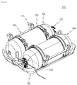
- FIG. 3 is a perspective view illustrating a gas tank assembly to which an apparatus for mounting a gas tank according to an exemplary embodiment of the present invention is applied, and referring to FIG. 3 , the exemplary embodiment 100 includes two gas tanks 102 and 104. Inlets of the gas tanks 102 and 104 are disposed while crossing each other. The gas tanks are mounted to a vehicle and serve as storing places storing high-pressure compressed gas supplied as fuel.
- the gas tank includes a cylindrical cylinder having an empty internal side, hemispherical liners provided at both ends of the cylinder, and fiber reinforced plastic layers provided on external surfaces of the liners.
- base frames 110 are provided as a part of the apparatus for mounting the gas tanks 102 and 104 to the vehicle.
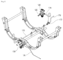
- the base frame 110 is formed in an approximate arch shape as illustrated in FIG. 4 , and is provided with supporting parts 116 for supporting the respective gas tanks at both sides based on a center of the base frame 110.
- the supporting part 116 has an approximately semicircular shape so as to correspond to an external appearance of the gas tank.
- Fixing parts 112 fixing the base frame 110 to the vehicle are provided at both ends of the base frame.
- the fixing parts 112 may be formed so as to be matched to a surface form of a corresponding vehicle body, and have plane forms in FIGs. 3 and 4 .
- a bolt inserting hole 114 to which a fastening bolt (not illustrated) as a fixing means for fixing the base frame to the vehicle body is fastened, is formed in the fixing part 112.
- a reinforcing part 118 is provided at an approximately center portion of the base frame.
- the reinforcing part 118 is formed to be thicker than other parts so as to prevent the base frame from being dropped in a down direction due to weight of the gas tank.
- a plurality of base frames is provided, and two base frames are provided in the illustrated example.
- the two base frames 110 are disposed while being spaced apart from each other by an appropriate distance according to a length of the gas tank, and guide frames for connecting the base frames 110 to each other are provided.
- a total of three guide frames is provided as illustrated, and the guide frame has a rod shape extended in a longitudinal direction thereof.
- the guide frames provided at both ends of the base frame are referred to as end guide frames 140
- the guide frame provided at a center of the base frame is referred to as a center guide frame 142.
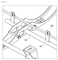
- a plurality of fastening brackets 144 is formed at the center guide frame 142.
- Each of the fastening brackets 144 has a plate form protruding from the center guide frame 142 in a predetermined direction, and includes a hook part to be described below so as to easily fasten a gas pipe.
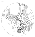
- pressure reducing valves 120 and 130 are mounted to the gas tanks 102 and 104, respectively.
- a pressure relief device PRD, not illustrated
- PRD including a fusible metal is provided in the pressure reducing valves 120 and 130, so that compressed gas stored inside the gas tank may be discharged to the outside by operating the PRD at fire.
- a fixing belt 150 as a fixing means for fixing the gas tank to the base frame is provided.
- the fixing belt 150 includes a pair of belts, of which one end 152 is hinge-coupled to a hinge coupling part 111 of the base frame as illustrated in FIG. 4 , and tightening parts 154 and 155 are formed at the other ends of the belts. Tightening bolts 156 are fastened to the two tightening parts, so that the fixing belt may fix the gas tank to the base frame by a rotation of the tightening bolt.
- a protecting cover 160 is provided on a lower surface of the gas tank.
- the protecting cover 160 is provided in order to protect the gas tank from foreign substances from a road surface or other impact, and is detachably mounted to the base frame. Further, observation windows 162 for checking a state of the pressure reducing valve even without separating the protecting cover are formed. In this case, it can be seen that the two observation windows 162 may be disposed in a zigzag form in accordance with the positions of the pressure reducing valves.
- the gas tank assembly includes a mutual connecting pipe 170 for connecting the two pressure reducing valves.
- the mutual connecting pipe 170 may serve to distribute gas supplied from the outside to the two tanks, or collect gas discharged from the two tanks and supply the collected gas to a fuel injection system.
- the mutual connecting pipe 170 is connected to each of the two pressure reducing valves and is applied as a pressurizing line, so that when gas is discharged from any one pressure reducing valve, the pressure is also transferred to the other pressure reducing valve, so that gas is discharged from all of the connected pressure reducing valves.
- the two pressure reducing valves are disposed in a zigzag form, so that in order to connect the two pressure reducing valves to each other, the mutual connecting pipe 170 needs to be extended in a longitudinal direction of the gas tank.
- one end of the mutual connecting pipe 170 may be connected with a T-shaped connector 172, and one side of the T-shaped connector 172 may be connected with a first pipe 174 connected with the pressure reducing valve 120.
- the remaining pipes except for the mutual connecting pipe 170 may be arbitrarily disposed according to a structure of a vehicle, to which the gas tank is mounted.
- a second pipe 176 connected with a fuel supply system or a gas charging port of the vehicle may also be connected to the pressure reducing valve 130 or the T-shaped connector.
- the fastening bracket 144 protrudes from the center guide frame 142 by a predetermined distance, and is provided with the hook part 146 for fastening the mutual connecting pipe 170 at one surface of the fastening bracket 144.
- the hook part 146 may have a predetermined form capable of fixing the mutual connecting pipe 170.
- a total of three fastening brackets is disposed along the center guide frame 142 in the longitudinal direction of the gas tank, so that the mutual connecting pipe 170 may be stably supported without being dropped or transformed.
- the method of charging gas in the two gas tanks, or the method of supplying fuel to a fuel supply system from the gas tank may adopt a method used in an existing gas tank assembly, so that a description thereof will be omitted. If fire is generated in the vehicle or fire is generated around the gas tank, the PRD mounted at each pressure reducing valve is heated. When a temperature of the PRD is heated to 110°C, at which the fusible metal may be melt, as described above, the gas charged inside the gas tank is discharged to the outside while the fusible metal is melted.
- the gas When a range of the fire is wide, the gas may be discharged from the two gas tanks while all of the two pressure reducing valves are heated.
- a range of the fire is small to influence only the pressure reducing valve installed at any one of the two pressure reducing valves, for example, the pressure reducing valve installed at the gas tank 102 disposed at a left side (based on FIG. 3 )
- the PRD provided at the corresponding pressure reducing valve is first operated to discharge gas, and the discharge pressure is transferred to the other pressure reducing valve connected by the mutual connecting pipe 170, so that the gas is discharged. That is, even when fire is generated at any one side based on the tank, the gas may be discharged from the entire tanks.
- two pressure reducing valves are all disposed at only one side of the gas tanks, so that when fire is generated at a side, at which the pressure reducing valve is installed, gas may be notably discharged, but when fire is generated at the opposite side of the pressure reducing valve, gas is not discharged until the tank is considerably heated, so that there are concerns that a pressure within the tank is excessively increased due to the fire.
- gas may be discharged from the entire gas tanks, thereby considerably improving safety.
- the two tanks are provided, but even in a case where the larger number of tanks is provided, when gas is discharged from one of the pressure reducing valves connected by the mutual connecting pipe, gas may be discharged by all of the connected pressure reducing valves.
Landscapes
- Engineering & Computer Science (AREA)
- Life Sciences & Earth Sciences (AREA)
- Sustainable Development (AREA)
- Sustainable Energy (AREA)
- Chemical & Material Sciences (AREA)
- Combustion & Propulsion (AREA)
- Transportation (AREA)
- Mechanical Engineering (AREA)
- Filling Or Discharging Of Gas Storage Vessels (AREA)
- Cooling, Air Intake And Gas Exhaust, And Fuel Tank Arrangements In Propulsion Units (AREA)
Applications Claiming Priority (1)
| Application Number | Priority Date | Filing Date | Title |
|---|---|---|---|
| KR1020150049806A KR101695242B1 (ko) | 2015-04-08 | 2015-04-08 | 차량의 가스탱크 마운트 장치 및 그를 이용한 가스탱크 조립체 |
Publications (2)
| Publication Number | Publication Date |
|---|---|
| EP3078529A2 true EP3078529A2 (de) | 2016-10-12 |
| EP3078529A3 EP3078529A3 (de) | 2016-12-14 |
Family
ID=55699452
Family Applications (1)
| Application Number | Title | Priority Date | Filing Date |
|---|---|---|---|
| EP16163617.0A Withdrawn EP3078529A3 (de) | 2015-04-08 | 2016-04-04 | Vorrichtung zur montage eines gastanks eines fahrzeugs und gastankanordnung damit |
Country Status (2)
| Country | Link |
|---|---|
| EP (1) | EP3078529A3 (de) |
| KR (1) | KR101695242B1 (de) |
Cited By (3)
| Publication number | Priority date | Publication date | Assignee | Title |
|---|---|---|---|---|
| CN106627112A (zh) * | 2016-12-13 | 2017-05-10 | 芜湖勤惠科技有限公司 | 重型卡车用lng气瓶框架 |
| CN110884344A (zh) * | 2019-12-27 | 2020-03-17 | 吉林大学 | 一种重型卡车用铝合金lng气瓶横向y形板支架装置 |
| CN111055676A (zh) * | 2019-12-31 | 2020-04-24 | 东风汽车股份有限公司 | 半包式cng防护装置 |
Families Citing this family (3)
| Publication number | Priority date | Publication date | Assignee | Title |
|---|---|---|---|---|
| KR20210085587A (ko) | 2019-12-31 | 2021-07-08 | 일진하이솔루스 주식회사 | 고압 가스 탱크 연결용 배출 배관 조립체 |
| KR20210085588A (ko) | 2019-12-31 | 2021-07-08 | 일진하이솔루스 주식회사 | 고압 가스 탱크 연결용 배출 배관 조립체 |
| KR102712163B1 (ko) * | 2022-09-29 | 2024-09-30 | 주식회사 동희산업 | 차량용 고압용기의 고정기구 |
Citations (1)
| Publication number | Priority date | Publication date | Assignee | Title |
|---|---|---|---|---|
| KR960005988Y1 (ko) | 1994-09-29 | 1996-07-19 | 한국가스공사 | 압축천연가스차량용 연료용기 |
Family Cites Families (8)
| Publication number | Priority date | Publication date | Assignee | Title |
|---|---|---|---|---|
| CA2384915C (en) * | 2001-05-04 | 2007-02-06 | Dynetek Industries Ltd. | Pressure vessel mounting system |
| JP3823806B2 (ja) * | 2001-10-30 | 2006-09-20 | 日産自動車株式会社 | 高圧容器の支持構造 |
| JP3813530B2 (ja) * | 2002-03-28 | 2006-08-23 | 本田技研工業株式会社 | 車両後部構造 |
| KR100851109B1 (ko) * | 2006-11-15 | 2008-08-08 | 기아자동차주식회사 | 연료전지차량의 후방충돌 충격흡수구조 |
| KR101509800B1 (ko) * | 2009-11-13 | 2015-04-08 | 현대자동차주식회사 | 차량의 가스탱크 탑재구조 |
| WO2014081833A1 (en) * | 2012-11-21 | 2014-05-30 | Trilogy Engineered Solutions | Methods and systems for compressed natural gas (cng) system |
| JP6102603B2 (ja) * | 2013-07-24 | 2017-03-29 | 日産自動車株式会社 | 燃料電池システムのタンク搭載ユニット |
| CN203438846U (zh) * | 2013-08-23 | 2014-02-19 | 北汽福田汽车股份有限公司 | 双燃料动力汽车气瓶固定装置 |
-
2015
- 2015-04-08 KR KR1020150049806A patent/KR101695242B1/ko active Active
-
2016
- 2016-04-04 EP EP16163617.0A patent/EP3078529A3/de not_active Withdrawn
Patent Citations (1)
| Publication number | Priority date | Publication date | Assignee | Title |
|---|---|---|---|---|
| KR960005988Y1 (ko) | 1994-09-29 | 1996-07-19 | 한국가스공사 | 압축천연가스차량용 연료용기 |
Cited By (3)
| Publication number | Priority date | Publication date | Assignee | Title |
|---|---|---|---|---|
| CN106627112A (zh) * | 2016-12-13 | 2017-05-10 | 芜湖勤惠科技有限公司 | 重型卡车用lng气瓶框架 |
| CN110884344A (zh) * | 2019-12-27 | 2020-03-17 | 吉林大学 | 一种重型卡车用铝合金lng气瓶横向y形板支架装置 |
| CN111055676A (zh) * | 2019-12-31 | 2020-04-24 | 东风汽车股份有限公司 | 半包式cng防护装置 |
Also Published As
| Publication number | Publication date |
|---|---|
| KR101695242B1 (ko) | 2017-01-11 |
| KR20160120574A (ko) | 2016-10-18 |
| EP3078529A3 (de) | 2016-12-14 |
Similar Documents
| Publication | Publication Date | Title |
|---|---|---|
| EP3078529A2 (de) | Vorrichtung zur montage eines gastanks eines fahrzeugs und gastankanordnung damit | |
| US20100018591A1 (en) | Fastening arrangement for a gas tank of a motor vehicle | |
| US12194839B2 (en) | Integrated fill system and method | |
| US10183576B2 (en) | Methods and systems for alternative fuel container support | |
| US6112760A (en) | Pressure relief system | |
| US11649932B2 (en) | Compressed gas discharge device | |
| EP3142887B1 (de) | Tanks zur bildung eines gestellaufbaus | |
| EP2098720B1 (de) | Brennstoffzufuhrsystem | |
| CA2287414A1 (en) | Cylinder mount for fuel system | |
| CA2809250C (en) | Tank support apparatus and method | |
| JP2023539765A (ja) | 圧力容器、圧力容器システム、および燃料レールを備えた自動車 | |
| CA2287396A1 (en) | Cng fuel supply system | |
| CN203857263U (zh) | 一种lng气瓶防护件及供气系统 | |
| JP2023504665A (ja) | ビークルのための加圧流体の貯蔵-配給アセンブリ | |
| JP2017100515A (ja) | 車両の燃料タンク取付構造 | |
| US20230408041A1 (en) | Fluid tank | |
| CA2287411A1 (en) | Tubing manifold with expansion loops | |
| CN114981160A (zh) | 燃料罐及船舶 | |
| CN115038606A (zh) | 用于燃料电池系统的箱设备 | |
| KR20140111667A (ko) | 내부 접근용 맨홀이 설비된, 압축 천연 가스의 해상 수송용 점검가능 컨테이너 | |
| US11649933B2 (en) | Integrated composite mounting structure for use in pressure vessels and pressure vessel systems | |
| KR20200116367A (ko) | Lng 벙커링 장치의 극저온용 벨로우즈 | |
| JP2008032053A (ja) | 高圧ガス供給装置及び高圧ガス供給設備 | |
| US20240424892A1 (en) | Fuel tank for gas-powered vehicle | |
| US20240369186A1 (en) | Tank device for storing a gaseous medium |
Legal Events
| Date | Code | Title | Description |
|---|---|---|---|
| PUAI | Public reference made under article 153(3) epc to a published international application that has entered the european phase |
Free format text: ORIGINAL CODE: 0009012 |
|
| 17P | Request for examination filed |
Effective date: 20160404 |
|
| AK | Designated contracting states |
Kind code of ref document: A2 Designated state(s): AL AT BE BG CH CY CZ DE DK EE ES FI FR GB GR HR HU IE IS IT LI LT LU LV MC MK MT NL NO PL PT RO RS SE SI SK SM TR |
|
| AX | Request for extension of the european patent |
Extension state: BA ME |
|
| PUAL | Search report despatched |
Free format text: ORIGINAL CODE: 0009013 |
|
| AK | Designated contracting states |
Kind code of ref document: A3 Designated state(s): AL AT BE BG CH CY CZ DE DK EE ES FI FR GB GR HR HU IE IS IT LI LT LU LV MC MK MT NL NO PL PT RO RS SE SI SK SM TR |
|
| AX | Request for extension of the european patent |
Extension state: BA ME |
|
| RIC1 | Information provided on ipc code assigned before grant |
Ipc: B60K 15/01 20060101AFI20161108BHEP Ipc: B60K 15/03 20060101ALI20161108BHEP Ipc: B60K 15/07 20060101ALI20161108BHEP |
|
| RIN1 | Information on inventor provided before grant (corrected) |
Inventor name: HEO, SEOK BONG Inventor name: CHOI, BONG WON Inventor name: PARK, JAE SUNG |
|
| STAA | Information on the status of an ep patent application or granted ep patent |
Free format text: STATUS: THE APPLICATION HAS BEEN WITHDRAWN |
|
| 18W | Application withdrawn |
Effective date: 20170406 |