EP3078543B1 - Vehicule de transport de marchandises au detail et/ou en vrac - Google Patents
Vehicule de transport de marchandises au detail et/ou en vrac Download PDFInfo
- Publication number
- EP3078543B1 EP3078543B1 EP16163858.0A EP16163858A EP3078543B1 EP 3078543 B1 EP3078543 B1 EP 3078543B1 EP 16163858 A EP16163858 A EP 16163858A EP 3078543 B1 EP3078543 B1 EP 3078543B1
- Authority
- EP
- European Patent Office
- Prior art keywords
- vehicle
- drum
- conveyor belt
- endless conveyor
- head drum
- Prior art date
- Legal status (The legal status is an assumption and is not a legal conclusion. Google has not performed a legal analysis and makes no representation as to the accuracy of the status listed.)
- Active
Links
Images





Classifications
-
- B—PERFORMING OPERATIONS; TRANSPORTING
- B60—VEHICLES IN GENERAL
- B60P—VEHICLES ADAPTED FOR LOAD TRANSPORTATION OR TO TRANSPORT, TO CARRY, OR TO COMPRISE SPECIAL LOADS OR OBJECTS
- B60P1/00—Vehicles predominantly for transporting loads and modified to facilitate loading, consolidating the load, or unloading
- B60P1/36—Vehicles predominantly for transporting loads and modified to facilitate loading, consolidating the load, or unloading using endless chains or belts thereon
- B60P1/38—Vehicles predominantly for transporting loads and modified to facilitate loading, consolidating the load, or unloading using endless chains or belts thereon forming the main load-transporting element or part thereof
-
- B—PERFORMING OPERATIONS; TRANSPORTING
- B65—CONVEYING; PACKING; STORING; HANDLING THIN OR FILAMENTARY MATERIAL
- B65G—TRANSPORT OR STORAGE DEVICES, e.g. CONVEYORS FOR LOADING OR TIPPING, SHOP CONVEYOR SYSTEMS OR PNEUMATIC TUBE CONVEYORS
- B65G15/00—Conveyors having endless load-conveying surfaces, i.e. belts and like continuous members, to which tractive effort is transmitted by means other than endless driving elements of similar configuration
- B65G15/60—Arrangements for supporting or guiding belts, e.g. by fluid jets
Definitions
- a vehicle of the type described in the preamble is the US 66 23 234 B1 refer to.
- the vehicle called the trailer, has an endless conveyor belt, the upper strand and lower strand of which, when tensioned, run parallel to one another over the entire length of the endless conveyor belt.
- Between the upper run and the lower run are also several support elements arranged parallel to the longitudinal alignment of the vehicle, such as L-brackets, closed profiles and rails, which cover the overall construction of the endless conveyor belt and its cross-section. especially increase the height.
- the known endless conveyor belt takes up a relatively large amount of space and reduces the load capacity of the vehicle.
- a special device for centering the belt run is not provided.
- the lower run is supported on two pressure rollers, which are arranged between the head drum and the rear drum and tension the lower run in such a way that a distance is formed between the upper run and lower run, the size of which is a diameter of the head drum and / or a diameter of the rear drum.
- the distance between the upper run and lower run is thus reduced, that is to say smaller, for example half as large as the diameter of the head or rear drum.
- the pressure rollers have a diameter which is smaller, preferably 3 to 6 times smaller, than the diameter of the head drum and / or the diameter of the rear drum.
- the pressure rollers thus require only a relatively small amount of space, but can nonetheless deflect the endless conveyor belt with little resistance.
- the fact that the center axes of the head and tail drums and the center axes of the smaller pressure rollers lie approximately in one plane also increases the wrap angle of the endless conveyor belt on the head and tail drums to more than 180 °. This increases the contact area of the endless conveyor belt and drums.
- the increased wrap angle also reduces the risk of slippage, with different slippage under slippage Speeds between the mechanical elements in frictional contact, namely drum and conveyor belt, is understood.
- the distance is sufficiently large to accommodate supporting elements in the space between the upper run and lower run, which support the upper run and ultimately carry the load stored on the upper run. So that the upper run is kept largely taut and sinks only slightly between the support elements, a plurality of slightly spaced support elements are provided below the upper run. Rotating support rollers are particularly preferred as support elements, since these ensure low-resistance movement of the upper run.
- At least one, preferably driven, cleaning element is preferably further arranged between the upper run and lower run.
- the cleaning element can be rotatable, in particular helical.
- the screw-like cleaning element has two oppositely arranged turns with which the dirt that has entered the area between the upper run and lower run can be removed to the sides in a simple manner via the openings located on the longitudinal beams.
- the cleaning element is preferably designed as a roller brush, optionally with turns.
- the longitudinal members of the chassis are connected to one another via at least one cross member, to which at least one support roller is preferably detachably attached.
- the support rollers can be in one piece or divided. In order to reduce the deflection of the support or support rollers, they are preferably divided into two and additionally supported at the separation point. The lower run - between the pressure rollers - can be supported on the support rollers and move with little friction.
- the diameter of the head and tail drum is relatively large, so deflection is easier and causes less flexing of the endless conveyor belt and better force transmission.
- the cleaning element can be driven via a belt or chain drive by a drive or gearwheel mounted on the head drum or rear drum.
- the head drum and / or rear drum are preferably designed in the form of a sheet metal tube and have an outer surface which is surrounded by a rubber or plastic layer.
- the rubber or plastic layer improves the frictional connection to the endless conveyor belt.
- the surface of the head drum and / or the rear drum is provided with a V-shaped profile, the tip of the V being arranged in the middle of the rear drum and / or head drum and pointing in the direction of rotation (S).
- the V-shaped profile means that the endless conveyor belt is centered when the rear and head drums are rotating. The center-centered conveyor belt is thus guided past the side members of the vehicle frame largely without friction, which reduces power consumption and wear.
- an agricultural vehicle 100 shown as a trailer, which has a chassis 1 on wheels 2 and one through a floor 6, two Side walls 3, 3 ', a front wall 4 and a rear wall 25 limited loading space 5 comprises.
- the rear wall 25 (tailgate) is movable and can be pivoted hydraulically.
- the chassis 1 has two longitudinal members 17, 17 ′ running parallel to one another and a plurality of cross members 32 arranged perpendicular to the longitudinal alignment of the chassis 1 (cf. Fig. 2 ) on which paired two-part support rollers 26 are attached.
- the support rollers 26 are removable in the illustrated embodiment.
- the function of the floor 6 is taken over by a movable endless conveyor belt 10 which wraps around a head drum 8 and a rear drum 9 (cf. Fig. 3 ) of a constant delivery length F, which replaces the conventional plate-shaped base.
- the endless conveyor belt 10 is driven by a drive designated "24" (cf. Fig. 2 ) on the rear drum 9.
- the drive 24 of the endless conveyor belt 10 is reversible.
- the endless conveyor belt 10 is a conveyor belt consisting of smooth rubber material reinforced with textile fabric.
- the rubber material is smooth and has no friction structure. Of course, it is possible to provide the rubber material with a friction-increasing surface structure.
- the endless conveyor belt 10 runs into a discharge area 14, which is arranged in a rear area 7 of the vehicle 100.
- a sealing strip 35 lying obliquely with respect to the bottom 6 (only one left sealing strip in the figures) is shown, which covers the side edges 31, 31 'of the endless conveyor belt 10.
- the endless conveyor belt 10 has an upper run 11 and a lower run 12 and a plurality of intermediate, removable support elements 13 which are mounted on longitudinal beams 17, 17 'of the chassis 1 (cf. Fig. 3 ) on.
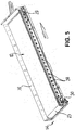
- the disassembly of the support elements 13 enables openings 28 (cf. Figures 2 , 4th and 5 ), which are inserted mirror-symmetrically to each other on both longitudinal beams 17, 17 '. Openings 29, 30 are also provided on the longitudinal beams 17, 17 '(cf. Figures 4 and 5 ) arranged for dismantling the head drum 8 and rear drum 9 accordingly.
- the lower run 12 is supported on two pressure rollers 15, 16 (cf. Figures 1 and 3rd ), which are arranged between the head drum 8 and rear drum 9.
- the pressure rollers 15, 16 are close to the head and rear drums 8, 9 and thereby tighten the lower run 12 in such a way that a distance A extending between the pressure rollers 15, 16 is formed between the upper run 11 and lower run 12.
- the distance A is smaller, in the present case about 2 times smaller than a diameter D1 of the head drum 8 or a diameter D2 of the rear drum 9.
- the lower run 12 (between the pressure rollers 15, 16) is supported on the two-part support rollers 26.
- the pressure roller 15, 16 also has a diameter D3, which is also smaller, in the present case 4 times smaller than the diameter D1, D2 of the head and rear drum 8; 9 is.
- a scraper 23 contacting the endless conveyor belt 10 is arranged in the discharge area 14, which ensures that the bulk particles adhering to the surface of the conveyor belt do not get under the lower strand 12.
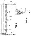
- the Figures 2 and 7 show a rotatable, on the longitudinal beams 17, 17 'mounted cleaning element 18, which is below the upper strand 11. Its task is to remove the dirt, such as loose particles, that collects between the upper run 11 and lower run 12 on sides 19, 19 'of the chassis 1 outside the longitudinal members 17, 17'.
- a helical design of the cleaning element 18 has proven to be very advantageous. It is particularly advantageous if the screw-shaped cleaning element 18 has two turns 20, 20 'arranged in opposite directions, with which the dirt is simultaneously on both sides 19, 19' outside of the longitudinal beams 17, 17 'via free spaces 34 (cf. Fig. 9 ) can be removed.
- the cleaning element 18 can be made of any material, for example rubber or plastic, preferably in the form of a roller brush.
- Fig. 7 Cleaning bristles 27 are shown sketchily, which are arranged along the entire length of the cleaning element 18 following the course of the screw.
- the cleaning element 18 is via a chain drive 22 from a gear 21 mounted on the head drum 8 (cf. Fig. 9 ) driven.
- the head drum 8 itself does not have its own drive motor. It is simply rotated by the conveyor belt.
- the tensioning of the endless conveyor belt 10 can be finely regulated.
- the clamping device 33 is a hydraulic cylinder with which the position of the head drum 8 and thus also of the cleaning element 18 can be readjusted.
- the advantage is that all moving parts, such as head drum 8, rear drum 9, support elements 13, cleaning element 18 and endless conveyor belt 10 can be removed and used again.
- the Figures 10 to 12 show the rear drum 9.
- the rear drum 9 and head drum 8 preferably have the same width B.
- the rear drum 9 is made from a sheet metal tube and has an outer lateral surface 37 onto which a plastic layer 38 is vulcanized.
- grooves 41 are made, which converge in the center of the drum 9 in a V shape in tips 40.
- the tips 40 point in the direction of rotation S of the rear drum 9 and thus in the conveying direction R.
- the grooves 40 form a profile 39 centering the endless conveyor belt 10.
- another centering profile for example in the form of arcuate grooves (not shown), can be provided.
- Different loads such as agricultural products, building rubble and general cargo, can be transported and unloaded in a simple manner with the vehicle 100.
Landscapes
- Engineering & Computer Science (AREA)
- Transportation (AREA)
- Mechanical Engineering (AREA)
- Structure Of Belt Conveyors (AREA)
Claims (14)
- Véhicule (100) de transport de marchandise en vrac et/ou au détail, comprenant un châssis (1) sur des roues (2) et un espace de chargement (5) dont le fond (6) est délimité par au moins deux parois latérales (3, 3') opposées, une paroi avant (4) et une paroi arrière (25) mobile;- le fond (6) étant formé par un tapis sans fin (10) mobile entourant un tambour de tête (8) et un tambour arrière (9) et dont la longueur de transport (F) est constante ;- le tapis sans fin (10) comportant un brin supérieur (11) et un brin inférieur (12) et des éléments de support (13) reposant entre, lesdits éléments étant placés à une certaine distance les uns des autres et étant disposés respectivement transversalement à une direction de transport (R) de façon à reposer contre les supports longitudinaux (17, 17') du châssis (1) ; et- le tapis sans fin (10) circulant dans une zone d'éjection (14) se trouvant dans une zone arrière (7) du véhicule (100) ; etcaractérisé en ce que:- le brin inférieur (12) s'appuie sur deux rouleaux compresseurs (15, 16) qui sont disposés entre le tambour de tête (8) et le tambour arrière (9) et comprimant le brin inférieur (12) s'étendant entre les rouleaux compresseurs (15, 16) de telle sorte qu'une distance (A) soit formée entre le brin supérieur (11) et le brin inférieur (12), l'ordre de grandeur de ladite distance étant inférieur à un diamètre (D1) du tambour de tête (8) et/ou à un diamètre (D2) du tambour arrière (9) ; et- le tambour arrière (8) et/ou le tambour de tête (9) étant pourvu d'un profilage (39) en forme de V, la pointe (40) du profilage (39) en forme de V étant disposée au centre du tambour de tête ou du tambour arrière (8, 9) et étant orientée dans la direction de rotation (S), de sorte que le tapis de transport sans fin (10) soit centré par le profilage (39) lorsque le tambour arrière et de tête (8, 9) tourne.
- Véhicule (100) selon la revendication 1, caractérisé en ce qu'au moins un élément de nettoyage (18) pivotable disposé au niveau des supports longitudinaux (17, 17') soit disposé en dessous du brin supérieur (11), ledit élément accumulant les particules de saleté ou autres arrivant dans la zone située entre le brin supérieur (11) et le brin inférieur (12) et les évacuant sur au moins un côté (19, 19') du châssis (1), à l'extérieur des supports longitudinaux (17, 17').
- Véhicule (100) selon l'une quelconque des revendications 1 ou 2, caractérisé en ce que les rouleaux compresseurs (15, 16) comportent respectivement un diamètre (D3) inférieur au diamètre (D1) du tambour de tête (8) et/ou au diamètre (D2) du tambour arrière (9).
- Véhicule (100) selon l'une quelconque des revendications 1 à 3, caractérisé en ce que les supports longitudinaux (17, 17') du châssis (1) sont reliés à au moins un support transversal (32) au niveau duquel au moins un rouleau de soutien (26) est disposé.
- Véhicule (100) selon l'une quelconque des revendications 1 à 4, caractérisé en ce que l'élément de nettoyage (18) comprend des soies de nettoyage (27).
- Véhicule (100) selon l'une quelconque des revendications 1 à 5, caractérisé en ce que l'élément de nettoyage (18) est en forme de vis sans fin.
- Véhicule (100) selon l'une quelconque des revendications 1 à 6, caractérisé en ce que l'élément de nettoyage (18) comporte deux spirales (20, 20') disposées en sens contraire.
- Véhicule (100) selon l'une quelconque des revendications 1 à 7, caractérisé en ce que l'élément de nettoyage (18) est entraîné par une roue dentée (21) disposée au niveau du tambour de tête (8) ou du tambour arrière (9) via un entraînement à chaîne (22).
- Véhicule (100) selon l'une quelconque des revendications 1 à 8, caractérisé en ce que le châssis (1) comprend des supports transversaux (32) au niveau desquels des éléments de support (26) sont disposés, ces éléments supportant le brin inférieur (12).
- Véhicule (100) selon l'une quelconque des revendications 1 à 9, caractérisé en ce que le tambour de tête (8) comporte une surface d'enveloppe (36) et/ou que le tambour arrière (9) comporte une surface d'enveloppe (37) entourée par une couche de caoutchouc ou de matière plastique (38).
- Véhicule (100) selon l'une quelconque des revendications 1 à 10, caractérisé en ce qu'au moins un racloir (23) mis au contact du tapis de transport sans fin (10) est disposé dans la zone d'éjection (14).
- Véhicule (100) selon l'une quelconque des revendications 1 à 11, caractérisé en ce que le tapis de transport sans fin (10) se compose de matière en caoutchouc renforcée de textile ou de tissu métallique.
- Véhicule (100) selon l'une quelconque des revendications 1 à 12, caractérisé en ce que toutes les parties mobiles, telles que le tambour de tête (8), le tambour arrière (9), les éléments de support (13), l'élément de nettoyage (18) et le tapis sans fin (10) sont démontables et réinsérables.
- Véhicule (100) selon l'une quelconque des revendications 1 à 13, caractérisé en ce que les supports longitudinaux (17, 17') comprennent des ouvertures (28, 29, 30) dont la largeur d'ouverture forme un espace libre à travers lequel les composants (8, 9, 13, 18) disposés entre le brin supérieur (11) et le brin inférieur (12) peuvent être démontés du châssis (1) d'un côté (31, 31') du tapis sans fin (10).
Applications Claiming Priority (1)
| Application Number | Priority Date | Filing Date | Title |
|---|---|---|---|
| DE102015004326.9A DE102015004326B3 (de) | 2015-04-09 | 2015-04-09 | Fahrzeug zum Transport von Schütt- und/oder Stückgut |
Publications (2)
| Publication Number | Publication Date |
|---|---|
| EP3078543A1 EP3078543A1 (fr) | 2016-10-12 |
| EP3078543B1 true EP3078543B1 (fr) | 2020-05-27 |
Family
ID=55697070
Family Applications (1)
| Application Number | Title | Priority Date | Filing Date |
|---|---|---|---|
| EP16163858.0A Active EP3078543B1 (fr) | 2015-04-09 | 2016-04-05 | Vehicule de transport de marchandises au detail et/ou en vrac |
Country Status (2)
| Country | Link |
|---|---|
| EP (1) | EP3078543B1 (fr) |
| DE (1) | DE102015004326B3 (fr) |
Families Citing this family (14)
| Publication number | Priority date | Publication date | Assignee | Title |
|---|---|---|---|---|
| DE102017000413B4 (de) * | 2017-01-18 | 2021-01-07 | Heinrich Gerdes | Transportfahrzeug |
| CN106853788B (zh) * | 2017-03-10 | 2023-10-27 | 江苏冠超物流科技有限公司 | 货物卸载机以及运输货车 |
| DE202017105085U1 (de) * | 2017-08-24 | 2017-09-21 | B. Strautmann & Söhne GmbH u. Co. KG | Fahrzeugaufbau mit integriertem Endlos-Förderband |
| CN108001944A (zh) * | 2018-01-16 | 2018-05-08 | 四川省自贡运输机械集团股份有限公司 | 胶带机自动清料装置 |
| DE102018120797A1 (de) * | 2018-08-27 | 2020-02-27 | Claas Selbstfahrende Erntemaschinen Gmbh | Selbstfahrender Mähdrescher mit einem endlos umlaufenden Rücklauf-Förderband und Rücklaufbaugruppe dafür |
| CN109747515A (zh) * | 2019-01-25 | 2019-05-14 | 威海顺丰专用车制造股份有限公司 | 一种往复式散货用运输车厢及汽车 |
| CN110341572A (zh) * | 2019-02-03 | 2019-10-18 | 柳州旭龙汽车部件有限公司 | 输送带自卸车车厢 |
| CN109878398A (zh) * | 2019-03-08 | 2019-06-14 | 柳州博实唯汽车科技股份有限公司 | 一种自卸车车厢 |
| US11999562B2 (en) * | 2019-05-03 | 2024-06-04 | Oshkosh Corporation | Front and side loading packers for electric refuse vehicle |
| CN110253737B (zh) * | 2019-06-17 | 2024-01-30 | 佛山市赛普飞特科技有限公司 | 一种用于砖坯粉料的布料设备 |
| CN113799673B (zh) * | 2020-06-17 | 2024-11-12 | 柳州博实唯汽车科技股份有限公司 | 用于输送带式自卸车的驱动与传动方法及装置 |
| CN112026621A (zh) * | 2020-09-27 | 2020-12-04 | 河南皇马车辆有限公司 | 一种散装粮食运输车 |
| CN112455311B (zh) * | 2020-11-30 | 2021-05-28 | 威海顺丰专用车制造股份有限公司 | 自卸半挂车 |
| CN117429507B (zh) * | 2023-12-08 | 2024-06-18 | 威海顺丰专用车制造股份有限公司 | 一种抽拉底板卸料的轻量化w型纵梁车厢 |
Family Cites Families (10)
| Publication number | Priority date | Publication date | Assignee | Title |
|---|---|---|---|---|
| US2284853A (en) * | 1940-11-01 | 1942-06-02 | Reuben E Wall | Unloading mechanism for trucks |
| DE1874371U (de) * | 1963-04-22 | 1963-06-20 | Josef Siepe K G | Grossraumfahrzeug mit foerderanlage. |
| US3478905A (en) * | 1968-05-31 | 1969-11-18 | Thomas A Strid | Conveyor for bulk grain hauling vehicles |
| US3593864A (en) * | 1969-12-04 | 1971-07-20 | Cci Corp | Self-unloading trailer |
| JPS6141638A (ja) * | 1984-08-01 | 1986-02-28 | Katsunori Tanada | コンテナトラツク等に配設したベルトコンベア− |
| US5118244A (en) * | 1989-09-22 | 1992-06-02 | Cook Peter P | Truck body structure and driven moving floor for self-unloading |
| DE9406406U1 (de) * | 1994-04-20 | 1994-08-04 | Ancra Jungfalk GmbH, 78234 Engen | Förderer für Verlade- und Transportanlagen von Nutzfahrzeugen |
| US6623234B1 (en) * | 1999-03-19 | 2003-09-23 | Dan Hill & Associates, Inc. | Non-linear sided trailer with continuous conveyor bed |
| DE102011102124A1 (de) * | 2011-05-20 | 2012-11-22 | 4BIO Trading GmbH | Pull- Box- System -Entleerrungssystem für landwirtschaftl. Produkte und Schüttgüter |
| DE202014101217U1 (de) * | 2014-03-17 | 2014-06-18 | Norbert Terbrack | Förderband, und damit ausgestattetes Fahrzeug |
-
2015
- 2015-04-09 DE DE102015004326.9A patent/DE102015004326B3/de not_active Expired - Fee Related
-
2016
- 2016-04-05 EP EP16163858.0A patent/EP3078543B1/fr active Active
Non-Patent Citations (1)
| Title |
|---|
| None * |
Also Published As
| Publication number | Publication date |
|---|---|
| EP3078543A1 (fr) | 2016-10-12 |
| DE102015004326B3 (de) | 2016-07-21 |
Similar Documents
| Publication | Publication Date | Title |
|---|---|---|
| EP3078543A1 (fr) | Vehicule de transport de marchandises au detail et/ou en vrac | |
| DE102009018163B4 (de) | Separate Vorrichtung für einen Förderer zum Transportieren von Gegenständen | |
| EP2563694B1 (fr) | Transporteur à bande courbée | |
| EP0541850B1 (fr) | Transporteur à palettes curviligne | |
| DE3317403C1 (de) | Stau-Haengefoerderer mit einer in der Horizontalebene umlaufenden,endlosen Trag- und Fuehrungsschiene | |
| EP2265521B1 (fr) | Bande transporteuse pour une installation de transport en longueur comportant des parois latérales s'étendant en longueur | |
| WO2018077670A1 (fr) | Système de transport | |
| DE3432553A1 (de) | Doppelgurtbandfoerderer | |
| EP2921430A1 (fr) | Bande de transport, et véhicule équipé de celle-ci | |
| DE2144290A1 (de) | Transportvorrichtung | |
| EP2039627A2 (fr) | Transporteur destiné au transport de marchandises | |
| DE19917368C2 (de) | Stetigförderer | |
| EP2754626B1 (fr) | Dispositif convoyeur à courroie concave | |
| AT516277B1 (de) | Förderanlage zum Transport von Gütern | |
| DE4443997C2 (de) | Fördervorrichtung zum geneigten oder senkrechten Fördern von Stückgut | |
| EP2058172A1 (fr) | Structure d'espace de charge avec une paroi frontale mobile et véhicule de transport muni d'une telle structure | |
| DE102004063704B4 (de) | Teleskop-Gurtförderer | |
| DE3003180A1 (de) | Endlos-kettenfoederer | |
| DE102015006815A1 (de) | Gurtförderelement mit Fördergurt | |
| DE20310185U1 (de) | Rollenbahn | |
| DE102004009842B4 (de) | Staurollenförderer | |
| DE2648236A1 (de) | Vorrichtung zum abstuetzen des leertrumes eines endlosen foerdermittels bei stetigfoerderern | |
| EP1557347B1 (fr) | Dispositif de montage d'un véhicule avec convoyeur à bande glissant sur un plateau. | |
| EP0982245B1 (fr) | Transporteur pour emballages | |
| WO2025131965A1 (fr) | Élément de rouleau de support pour transporteur à rouleaux |
Legal Events
| Date | Code | Title | Description |
|---|---|---|---|
| PUAI | Public reference made under article 153(3) epc to a published international application that has entered the european phase |
Free format text: ORIGINAL CODE: 0009012 |
|
| AK | Designated contracting states |
Kind code of ref document: A1 Designated state(s): AL AT BE BG CH CY CZ DE DK EE ES FI FR GB GR HR HU IE IS IT LI LT LU LV MC MK MT NL NO PL PT RO RS SE SI SK SM TR |
|
| AX | Request for extension of the european patent |
Extension state: BA ME |
|
| STAA | Information on the status of an ep patent application or granted ep patent |
Free format text: STATUS: REQUEST FOR EXAMINATION WAS MADE |
|
| 17P | Request for examination filed |
Effective date: 20170323 |
|
| RBV | Designated contracting states (corrected) |
Designated state(s): AL AT BE BG CH CY CZ DE DK EE ES FI FR GB GR HR HU IE IS IT LI LT LU LV MC MK MT NL NO PL PT RO RS SE SI SK SM TR |
|
| STAA | Information on the status of an ep patent application or granted ep patent |
Free format text: STATUS: EXAMINATION IS IN PROGRESS |
|
| 17Q | First examination report despatched |
Effective date: 20190415 |
|
| GRAP | Despatch of communication of intention to grant a patent |
Free format text: ORIGINAL CODE: EPIDOSNIGR1 |
|
| STAA | Information on the status of an ep patent application or granted ep patent |
Free format text: STATUS: GRANT OF PATENT IS INTENDED |
|
| INTG | Intention to grant announced |
Effective date: 20191105 |
|
| GRAJ | Information related to disapproval of communication of intention to grant by the applicant or resumption of examination proceedings by the epo deleted |
Free format text: ORIGINAL CODE: EPIDOSDIGR1 |
|
| STAA | Information on the status of an ep patent application or granted ep patent |
Free format text: STATUS: EXAMINATION IS IN PROGRESS |
|
| GRAP | Despatch of communication of intention to grant a patent |
Free format text: ORIGINAL CODE: EPIDOSNIGR1 |
|
| STAA | Information on the status of an ep patent application or granted ep patent |
Free format text: STATUS: GRANT OF PATENT IS INTENDED |
|
| GRAS | Grant fee paid |
Free format text: ORIGINAL CODE: EPIDOSNIGR3 |
|
| INTC | Intention to grant announced (deleted) | ||
| INTG | Intention to grant announced |
Effective date: 20200318 |
|
| GRAA | (expected) grant |
Free format text: ORIGINAL CODE: 0009210 |
|
| STAA | Information on the status of an ep patent application or granted ep patent |
Free format text: STATUS: THE PATENT HAS BEEN GRANTED |
|
| AK | Designated contracting states |
Kind code of ref document: B1 Designated state(s): AL AT BE BG CH CY CZ DE DK EE ES FI FR GB GR HR HU IE IS IT LI LT LU LV MC MK MT NL NO PL PT RO RS SE SI SK SM TR |
|
| REG | Reference to a national code |
Ref country code: GB Ref legal event code: FG4D Free format text: NOT ENGLISH |
|
| REG | Reference to a national code |
Ref country code: CH Ref legal event code: EP |
|
| REG | Reference to a national code |
Ref country code: AT Ref legal event code: REF Ref document number: 1274229 Country of ref document: AT Kind code of ref document: T Effective date: 20200615 |
|
| REG | Reference to a national code |
Ref country code: DE Ref legal event code: R096 Ref document number: 502016010028 Country of ref document: DE |
|
| REG | Reference to a national code |
Ref country code: LT Ref legal event code: MG4D |
|
| PG25 | Lapsed in a contracting state [announced via postgrant information from national office to epo] |
Ref country code: LT Free format text: LAPSE BECAUSE OF FAILURE TO SUBMIT A TRANSLATION OF THE DESCRIPTION OR TO PAY THE FEE WITHIN THE PRESCRIBED TIME-LIMIT Effective date: 20200527 Ref country code: GR Free format text: LAPSE BECAUSE OF FAILURE TO SUBMIT A TRANSLATION OF THE DESCRIPTION OR TO PAY THE FEE WITHIN THE PRESCRIBED TIME-LIMIT Effective date: 20200828 Ref country code: SE Free format text: LAPSE BECAUSE OF FAILURE TO SUBMIT A TRANSLATION OF THE DESCRIPTION OR TO PAY THE FEE WITHIN THE PRESCRIBED TIME-LIMIT Effective date: 20200527 Ref country code: NO Free format text: LAPSE BECAUSE OF FAILURE TO SUBMIT A TRANSLATION OF THE DESCRIPTION OR TO PAY THE FEE WITHIN THE PRESCRIBED TIME-LIMIT Effective date: 20200827 Ref country code: IS Free format text: LAPSE BECAUSE OF FAILURE TO SUBMIT A TRANSLATION OF THE DESCRIPTION OR TO PAY THE FEE WITHIN THE PRESCRIBED TIME-LIMIT Effective date: 20200927 Ref country code: FI Free format text: LAPSE BECAUSE OF FAILURE TO SUBMIT A TRANSLATION OF THE DESCRIPTION OR TO PAY THE FEE WITHIN THE PRESCRIBED TIME-LIMIT Effective date: 20200527 Ref country code: PT Free format text: LAPSE BECAUSE OF FAILURE TO SUBMIT A TRANSLATION OF THE DESCRIPTION OR TO PAY THE FEE WITHIN THE PRESCRIBED TIME-LIMIT Effective date: 20200928 |
|
| REG | Reference to a national code |
Ref country code: NL Ref legal event code: MP Effective date: 20200527 |
|
| PG25 | Lapsed in a contracting state [announced via postgrant information from national office to epo] |
Ref country code: RS Free format text: LAPSE BECAUSE OF FAILURE TO SUBMIT A TRANSLATION OF THE DESCRIPTION OR TO PAY THE FEE WITHIN THE PRESCRIBED TIME-LIMIT Effective date: 20200527 Ref country code: HR Free format text: LAPSE BECAUSE OF FAILURE TO SUBMIT A TRANSLATION OF THE DESCRIPTION OR TO PAY THE FEE WITHIN THE PRESCRIBED TIME-LIMIT Effective date: 20200527 Ref country code: BG Free format text: LAPSE BECAUSE OF FAILURE TO SUBMIT A TRANSLATION OF THE DESCRIPTION OR TO PAY THE FEE WITHIN THE PRESCRIBED TIME-LIMIT Effective date: 20200827 Ref country code: LV Free format text: LAPSE BECAUSE OF FAILURE TO SUBMIT A TRANSLATION OF THE DESCRIPTION OR TO PAY THE FEE WITHIN THE PRESCRIBED TIME-LIMIT Effective date: 20200527 |
|
| PG25 | Lapsed in a contracting state [announced via postgrant information from national office to epo] |
Ref country code: NL Free format text: LAPSE BECAUSE OF FAILURE TO SUBMIT A TRANSLATION OF THE DESCRIPTION OR TO PAY THE FEE WITHIN THE PRESCRIBED TIME-LIMIT Effective date: 20200527 Ref country code: AL Free format text: LAPSE BECAUSE OF FAILURE TO SUBMIT A TRANSLATION OF THE DESCRIPTION OR TO PAY THE FEE WITHIN THE PRESCRIBED TIME-LIMIT Effective date: 20200527 |
|
| PG25 | Lapsed in a contracting state [announced via postgrant information from national office to epo] |
Ref country code: IT Free format text: LAPSE BECAUSE OF FAILURE TO SUBMIT A TRANSLATION OF THE DESCRIPTION OR TO PAY THE FEE WITHIN THE PRESCRIBED TIME-LIMIT Effective date: 20200527 Ref country code: DK Free format text: LAPSE BECAUSE OF FAILURE TO SUBMIT A TRANSLATION OF THE DESCRIPTION OR TO PAY THE FEE WITHIN THE PRESCRIBED TIME-LIMIT Effective date: 20200527 Ref country code: EE Free format text: LAPSE BECAUSE OF FAILURE TO SUBMIT A TRANSLATION OF THE DESCRIPTION OR TO PAY THE FEE WITHIN THE PRESCRIBED TIME-LIMIT Effective date: 20200527 Ref country code: SM Free format text: LAPSE BECAUSE OF FAILURE TO SUBMIT A TRANSLATION OF THE DESCRIPTION OR TO PAY THE FEE WITHIN THE PRESCRIBED TIME-LIMIT Effective date: 20200527 Ref country code: RO Free format text: LAPSE BECAUSE OF FAILURE TO SUBMIT A TRANSLATION OF THE DESCRIPTION OR TO PAY THE FEE WITHIN THE PRESCRIBED TIME-LIMIT Effective date: 20200527 Ref country code: CZ Free format text: LAPSE BECAUSE OF FAILURE TO SUBMIT A TRANSLATION OF THE DESCRIPTION OR TO PAY THE FEE WITHIN THE PRESCRIBED TIME-LIMIT Effective date: 20200527 Ref country code: ES Free format text: LAPSE BECAUSE OF FAILURE TO SUBMIT A TRANSLATION OF THE DESCRIPTION OR TO PAY THE FEE WITHIN THE PRESCRIBED TIME-LIMIT Effective date: 20200527 |
|
| PG25 | Lapsed in a contracting state [announced via postgrant information from national office to epo] |
Ref country code: SK Free format text: LAPSE BECAUSE OF FAILURE TO SUBMIT A TRANSLATION OF THE DESCRIPTION OR TO PAY THE FEE WITHIN THE PRESCRIBED TIME-LIMIT Effective date: 20200527 Ref country code: PL Free format text: LAPSE BECAUSE OF FAILURE TO SUBMIT A TRANSLATION OF THE DESCRIPTION OR TO PAY THE FEE WITHIN THE PRESCRIBED TIME-LIMIT Effective date: 20200527 |
|
| REG | Reference to a national code |
Ref country code: DE Ref legal event code: R097 Ref document number: 502016010028 Country of ref document: DE |
|
| PLBE | No opposition filed within time limit |
Free format text: ORIGINAL CODE: 0009261 |
|
| STAA | Information on the status of an ep patent application or granted ep patent |
Free format text: STATUS: NO OPPOSITION FILED WITHIN TIME LIMIT |
|
| 26N | No opposition filed |
Effective date: 20210302 |
|
| PG25 | Lapsed in a contracting state [announced via postgrant information from national office to epo] |
Ref country code: SI Free format text: LAPSE BECAUSE OF FAILURE TO SUBMIT A TRANSLATION OF THE DESCRIPTION OR TO PAY THE FEE WITHIN THE PRESCRIBED TIME-LIMIT Effective date: 20200527 |
|
| PG25 | Lapsed in a contracting state [announced via postgrant information from national office to epo] |
Ref country code: MC Free format text: LAPSE BECAUSE OF FAILURE TO SUBMIT A TRANSLATION OF THE DESCRIPTION OR TO PAY THE FEE WITHIN THE PRESCRIBED TIME-LIMIT Effective date: 20200527 |
|
| GBPC | Gb: european patent ceased through non-payment of renewal fee |
Effective date: 20210405 |
|
| PG25 | Lapsed in a contracting state [announced via postgrant information from national office to epo] |
Ref country code: LU Free format text: LAPSE BECAUSE OF NON-PAYMENT OF DUE FEES Effective date: 20210405 |
|
| REG | Reference to a national code |
Ref country code: BE Ref legal event code: MM Effective date: 20210430 |
|
| PG25 | Lapsed in a contracting state [announced via postgrant information from national office to epo] |
Ref country code: LI Free format text: LAPSE BECAUSE OF NON-PAYMENT OF DUE FEES Effective date: 20210430 Ref country code: CH Free format text: LAPSE BECAUSE OF NON-PAYMENT OF DUE FEES Effective date: 20210430 Ref country code: FR Free format text: LAPSE BECAUSE OF NON-PAYMENT OF DUE FEES Effective date: 20210430 Ref country code: GB Free format text: LAPSE BECAUSE OF NON-PAYMENT OF DUE FEES Effective date: 20210405 |
|
| PG25 | Lapsed in a contracting state [announced via postgrant information from national office to epo] |
Ref country code: IE Free format text: LAPSE BECAUSE OF NON-PAYMENT OF DUE FEES Effective date: 20210405 |
|
| REG | Reference to a national code |
Ref country code: AT Ref legal event code: MM01 Ref document number: 1274229 Country of ref document: AT Kind code of ref document: T Effective date: 20210405 |
|
| PG25 | Lapsed in a contracting state [announced via postgrant information from national office to epo] |
Ref country code: BE Free format text: LAPSE BECAUSE OF NON-PAYMENT OF DUE FEES Effective date: 20210430 |
|
| PG25 | Lapsed in a contracting state [announced via postgrant information from national office to epo] |
Ref country code: AT Free format text: LAPSE BECAUSE OF NON-PAYMENT OF DUE FEES Effective date: 20210405 |
|
| PG25 | Lapsed in a contracting state [announced via postgrant information from national office to epo] |
Ref country code: HU Free format text: LAPSE BECAUSE OF FAILURE TO SUBMIT A TRANSLATION OF THE DESCRIPTION OR TO PAY THE FEE WITHIN THE PRESCRIBED TIME-LIMIT; INVALID AB INITIO Effective date: 20160405 |
|
| PG25 | Lapsed in a contracting state [announced via postgrant information from national office to epo] |
Ref country code: CY Free format text: LAPSE BECAUSE OF FAILURE TO SUBMIT A TRANSLATION OF THE DESCRIPTION OR TO PAY THE FEE WITHIN THE PRESCRIBED TIME-LIMIT Effective date: 20200527 |
|
| PG25 | Lapsed in a contracting state [announced via postgrant information from national office to epo] |
Ref country code: MK Free format text: LAPSE BECAUSE OF FAILURE TO SUBMIT A TRANSLATION OF THE DESCRIPTION OR TO PAY THE FEE WITHIN THE PRESCRIBED TIME-LIMIT Effective date: 20200527 |
|
| PG25 | Lapsed in a contracting state [announced via postgrant information from national office to epo] |
Ref country code: TR Free format text: LAPSE BECAUSE OF FAILURE TO SUBMIT A TRANSLATION OF THE DESCRIPTION OR TO PAY THE FEE WITHIN THE PRESCRIBED TIME-LIMIT Effective date: 20200527 |
|
| PG25 | Lapsed in a contracting state [announced via postgrant information from national office to epo] |
Ref country code: MT Free format text: LAPSE BECAUSE OF FAILURE TO SUBMIT A TRANSLATION OF THE DESCRIPTION OR TO PAY THE FEE WITHIN THE PRESCRIBED TIME-LIMIT Effective date: 20200527 |
|
| PGFP | Annual fee paid to national office [announced via postgrant information from national office to epo] |
Ref country code: DE Payment date: 20250305 Year of fee payment: 10 |