EP3078582B1 - Bremsvorrichtung und grätschsitzfahrzeug - Google Patents
Bremsvorrichtung und grätschsitzfahrzeug Download PDFInfo
- Publication number
- EP3078582B1 EP3078582B1 EP14866709.0A EP14866709A EP3078582B1 EP 3078582 B1 EP3078582 B1 EP 3078582B1 EP 14866709 A EP14866709 A EP 14866709A EP 3078582 B1 EP3078582 B1 EP 3078582B1
- Authority
- EP
- European Patent Office
- Prior art keywords
- brake
- rear wheel
- braking force
- hydraulic pressure
- front wheel
- Prior art date
- Legal status (The legal status is an assumption and is not a legal conclusion. Google has not performed a legal analysis and makes no representation as to the accuracy of the status listed.)
- Active
Links
Images











Classifications
-
- B—PERFORMING OPERATIONS; TRANSPORTING
- B62—LAND VEHICLES FOR TRAVELLING OTHERWISE THAN ON RAILS
- B62L—BRAKES SPECIALLY ADAPTED FOR CYCLES
- B62L3/00—Brake-actuating mechanisms; Arrangements thereof
- B62L3/08—Mechanisms specially adapted for braking more than one wheel
-
- B—PERFORMING OPERATIONS; TRANSPORTING
- B60—VEHICLES IN GENERAL
- B60T—VEHICLE BRAKE CONTROL SYSTEMS OR PARTS THEREOF; BRAKE CONTROL SYSTEMS OR PARTS THEREOF, IN GENERAL; ARRANGEMENT OF BRAKING ELEMENTS ON VEHICLES IN GENERAL; PORTABLE DEVICES FOR PREVENTING UNWANTED MOVEMENT OF VEHICLES; VEHICLE MODIFICATIONS TO FACILITATE COOLING OF BRAKES
- B60T8/00—Arrangements for adjusting wheel-braking force to meet varying vehicular or ground-surface conditions, e.g. limiting or varying distribution of braking force
- B60T8/17—Using electrical or electronic regulation means to control braking
- B60T8/1701—Braking or traction control means specially adapted for particular types of vehicles
- B60T8/1706—Braking or traction control means specially adapted for particular types of vehicles for single-track vehicles, e.g. motorcycles
-
- B—PERFORMING OPERATIONS; TRANSPORTING
- B62—LAND VEHICLES FOR TRAVELLING OTHERWISE THAN ON RAILS
- B62K—CYCLES; CYCLE FRAMES; CYCLE STEERING DEVICES; RIDER-OPERATED TERMINAL CONTROLS SPECIALLY ADAPTED FOR CYCLES; CYCLE AXLE SUSPENSIONS; CYCLE SIDECARS, FORECARS, OR THE LIKE
- B62K11/00—Motorcycles, engine-assisted cycles or motor scooters with one or two wheels
-
- B—PERFORMING OPERATIONS; TRANSPORTING
- B60—VEHICLES IN GENERAL
- B60L—PROPULSION OF ELECTRICALLY-PROPELLED VEHICLES; SUPPLYING ELECTRIC POWER FOR AUXILIARY EQUIPMENT OF ELECTRICALLY-PROPELLED VEHICLES; ELECTRODYNAMIC BRAKE SYSTEMS FOR VEHICLES IN GENERAL; MAGNETIC SUSPENSION OR LEVITATION FOR VEHICLES; MONITORING OPERATING VARIABLES OF ELECTRICALLY-PROPELLED VEHICLES; ELECTRIC SAFETY DEVICES FOR ELECTRICALLY-PROPELLED VEHICLES
- B60L2200/00—Type of vehicles
- B60L2200/12—Bikes
Definitions
- the present invention relates to a brake device and a straddled vehicle including the brake device.
- Patent Document 1 a front/rear wheel conjunction brake device capable of distributing a braking force to a front wheel and a rear wheel in order to reduce an operation load of the driver in the case where any one operation of operation means of a plurality of systems (a brake lever and a brake pedal) is performed is described.
- a braking force is distributed to a front wheel and a rear wheel by a single operation means also in a straddled vehicle, such as a motorcycle, in order to reduce a load applied in a braking operation of the driver as in the front/rear wheel conjunction brake device of Patent Document 1.
- a straddled vehicle it is different for a straddled vehicle than for an automobile.
- the driver With a main switch being turned off (a power OFF state), the driver often moves a vehicle while being seated on a seat and kicking a road surface with his or her feet, or gets off the vehicle and pushes the vehicle while walking.
- the front/rear wheel conjunction brake device of Patent Document 1 the front/rear wheel conjunction brake control by the ECU and the electronic control actuator is not performed.
- US 2005/0168060 A1 discloses a brake device according to the preamble of claim 1.
- An object of the present invention is to provide a brake device capable of reducing a load applied in a braking operation by a driver and improving comfort during the braking operation, and a straddled vehicle including the brake device.
- the operation amount of the operation member by the driver is detected by the operation amount detector.
- the first and second target braking forces are acquired from the relationship stored in the storage based on the operation amount detected by the operation amount detector.
- the hydraulic pressure corresponding to the acquired first target braking force is supplied to the first brake, and the hydraulic pressure corresponding to the acquired second target braking force is supplied to the second brake.
- an appropriate braking force corresponding to the operation amount can be respectively distributed to the front wheel and the rear wheel by operation of the single operation member by the driver.
- the hydraulic pressure control device does not operate, and the hydraulic pressure control is not performed.
- the hydraulic pressures corresponding to the operation amount of the operation member by the driver are supplied to the first and second brakes by the hydraulic pressure generation device.
- the driver can manually adjust the braking forces exerted on the front wheel and the rear wheel by operating the single operation member.
- the relationship between the operation amount of the operation member and the total of the braking forces exerted on the front wheel and the rear wheel during the operation of the hydraulic pressure control is equal to the relationship between the operation amount of the operation member and the total of the braking forces exerted on the front wheel and the rear wheel during the non-operation of the hydraulic pressure control.
- the present invention enables a reduction in a load applied in the braking operation by the driver and improvement of the comfort during the braking operation.
- the straddled vehicle of the present embodiment is a motorcycle.
- Fig. 1 is a schematic side view showing the schematic configuration of the motorcycle according to the present embodiment.
- forward, rearward, leftward, and rightward as viewed from a driver who is seated on a seat of the motorcycle 1 are referred to as forward, rearward, leftward and rightward, respectively.
- An arrow F in the diagram indicates forward, and an arrow R indicates rearward.
- the motorcycle 1 of Fig. 1 is a scooter-type vehicle, and includes a vehicle main body 2, a front wheel 3, a rear wheel 4, a brake device 5, an engine 6 and a handle 7.
- the vehicle main body 2 is constituted by a vehicle body frame, a vehicle body cover, a head light, a seat and the like.
- a front fork (not shown) is provided at a front portion of the vehicle main body 2 to be swingable to the left and right, and the front wheel 3 is provided at a lower end of the front fork to be rotatable.
- a pair of annular disc rotors 31 is provided on both sides of the front wheel 3.
- the rear wheel 4 is provided at a swing arm (not shown) at a rear portion of the vehicle main body 2 to be rotatable.
- the engine 6 is provided at the vehicle main body 2 in front of the rear wheel 4.
- the rear wheel 4 is rotated by a torque of the engine 6.
- An annular disc rotor 41 is provided on the side of the rear wheel 4.
- the brake device 5 includes a front wheel brake 51, a rear wheel brake 52, a brake control device 53, a brake lever 54, which is a single operation member, and the like.
- the front wheel brake 51 is attached to the front fork.
- the rear wheel brake 52 is attached to the swing arm.
- the brake control device 53 is provided at the vehicle main body 2. Details of the brake device 5 will be described below.
- the handle 7 is attached to an upper end of the front fork.
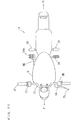
- Fig. 2 is a plan view showing the handle 7.
- the handle 7 includes a handlebar 71.
- An accelerator grip 72 is provided at the right end of the handlebar 71.
- a tandem master cylinder MC is provided at the center of the left half portion of the handlebar 71.
- the brake lever 54 is provided at the center of the left half portion of the handlebar 71 to extend to a position in the vicinity of the left end.
- a reserve tank RT (not shown) of Fig. 1 is attached to an upper surface of the tandem master cylinder MC.
- a switch box 73 is attached to the right half portion of the handlebar 71 to be adjacent to an inner end of the accelerator grip 72. Further, a switch box 74 is attached to the left half portion of the handlebar 71 to be adjacent to an outer end of the tandem master cylinder MC. A characteristics switching switch SW is provided at the switch box 74. The characteristics switching switch SW may be provided at the switch box 73.
- a support member 80 may be provided to extend from the switch box 73 in the right half portion of the handlebar 71 to a position in the vicinity of the right end, and the characteristics switching switch SW may be provided at the support member 80.
- a driver adjusts the output of the engine 6 by operating the accelerator grip 72 with his or her right hand. Further, the driver performs deceleration of the motorcycle 1 by operating the brake lever 54 with his or her left hand.
- the transmission of power from the engine 6 to the rear wheel 4 is performed via an automatic transmission. Disconnection and connection of a power transmission path are automatically performed by a power disconnection/connection mechanism such as a centrifugal clutch or the like. Therefore, a clutch lever is not provided at the handlebar 71. Further, in the case where an electric motor is employed as a motor instead of the engine 6, the automatic transmission and the power disconnection/connection mechanism are not provided, and the output of the electric motor is directly transmitted to the rear wheel 4. Also in this case, the clutch lever is not provided at the handlebar 71.
- the brake lever 54 that is a single operation member is provided on the opposite side of the accelerator grip 72, so that the driver can perform adjustment of the braking forces and adjustment of the driving forces for the front wheel 3 and the rear wheel 4 simultaneously and independently. Therefore, good driving operability during acceleration and deceleration of the motorcycle 1 can be ensured, and behavior and a speed of the motorcycle 1 can be easily adjusted.
- Fig. 3 is a schematic diagram showing the configuration of the brake device 5.
- the brake device 5 includes the front wheel brake 51, the rear wheel brake 52, the brake control device 53, the brake lever 54, the reserve tank RT, the tandem master cylinder MC, a master pressure sensor MS, a front caliper pressure sensor FS and a rear caliper pressure sensor RS.
- the brake control device 53 is constituted by an ECU (an Electronic Control Unit) 55 and an oil pressure unit 56.
- a primary piston PP and a secondary piston SP are provided to be movable in an axis direction.
- a first pressure chamber PR1 and a second pressure chamber PR2 are formed in the tandem master cylinder MC.
- the primary piston PP and the secondary piston SP are moved in the axis direction by an operation of the brake lever 54.
- equal pressures are generated in the first pressure chamber PR1 and the second pressure chamber PR2.
- the first pressure chamber PR1 is connected to the oil pressure unit 56 via an oil pressure pipe P11.
- the master pressure sensor MS is attached to the oil pressure pipe P11.
- the master pressure sensor MS detects the pressure in the oil pressure pipe P11.
- the second pressure chamber PR2 is connected to the oil pressure unit 56 via an oil pressure pipe P12.
- the reserve tank RT is connected to the oil pressure unit 56 via an oil pressure pipe P13. Further, the reserve tank RT is connected to the first pressure chamber PR1 of the tandem master cylinder MC via oil pressure pipes P14, P15, and is connected to the second pressure chamber PR2 of the tandem master cylinder MC via the oil pressure pipes P14, P16.
- the front wheel brake 51 includes a pair of front calipers 510.
- Each front caliper 510 includes a front wheel cylinder FWC and a front wheel piston FWP. Further, each front caliper 510 includes a pair of brake pads BP that press the disc rotor 31.
- the rear wheel brake 52 includes a rear caliper 520.
- the rear caliper 520 includes a rear wheel cylinder RWC and a rear wheel piston RWP. Further, the rear caliper 520 includes a pair of brake pads BP that press the disc rotor 41.
- the front wheel cylinders FWC are connected to the oil pressure unit 56 via an oil pressure pipe P21.
- a front caliper pressure sensor FS is attached to the oil pressure pipe P21.
- the rear wheel cylinder RWC is connected to the oil pressure unit 56 via an oil pressure pipe P22.
- a rear caliper pressure sensor RS is attached to the oil pressure pipe P22.
- the front caliper pressure sensor FS detects the pressure in the oil pressure pipe P21
- the rear caliper pressure sensor RS detects the pressure in the oil pressure pipe P22.
- An operation amount of the brake lever 54 corresponds to the pressure detected by the master pressure sensor MS.
- the braking force exerted on the front wheel 3 corresponds to the pressure detected by the front caliper pressure sensor FS. Further, the braking force exerted on the rear wheel 4 corresponds to the pressure detected by the rear caliper pressure sensor RS.
- the ECU 55 acquires the operation amount of the brake lever 54 based on the pressure detected by the master pressure sensor MS. Further, the ECU 55 detects the braking forces exerted on the front wheel 3 and the rear wheel 4 based on the pressures detected by the front caliper pressure sensor FS and the rear caliper pressure sensor RS.
- the brake control device 53 performs hydraulic pressure control.
- target braking forces to be respectively exerted on the front wheel 3 and the rear wheel 4 are acquired from operation amount-front/rear wheel target braking force characteristics, described below, based on the operation amount of the brake lever 54, and the oil pressures corresponding to the acquired target braking forces are respectively supplied to the front wheel brake 51 and the rear wheel brake 52.
- the braking forces are respectively exerted on the front wheel 3 and the rear wheel 4 by independent oil pressure systems.
- a state in which the hydraulic pressure control of the brake control device 53 is operating is referred to as a control ON state
- a state in which the hydraulic pressure control of the brake control device 53 is not operating is referred to as a control OFF state.
- the brake control device 53 When the main switch is turned off in the control ON state of the brake control device 53 or when a problem with the electric system such as the master pressure sensor MS is detected, the brake control device 53 is shifted to the control OFF state.
- Fig. 4 is a schematic diagram mainly showing the configuration of the oil pressure unit 56 of the brake device 5 of Fig. 3 .
- the oil pressure unit 56 includes a pump PM, a front master cut valve FV, a rear master cut valve RV, pressurization valves IV1, IV2 and depressurization valves DV1, DV2.
- An oil pressure pipe P31 and an oil pressure pipe P33 are connected to the oil pressure pipe P13.
- the pump PM is inserted between the oil pressure pipe P31 and an oil pressure pipe P32.
- the front master cut FV is inserted between the oil pressure pipe P11 and the oil pressure pipe P21.
- the rear master cut valve RV is inserted between the oil pressure pipe P12 and the oil pressure pipe P22.
- An oil pressure pipe P34 is provided to branch from the oil pressure pipe P21, and an oil pressure pipe P35 is provided to branch from the oil pressure pipe P22.
- the pressurization valve IV1 is inserted between the oil pressure pipe P32 and the oil pressure pipe P34, and the pressurization valve IV2 is inserted between the oil pressure pipe P32 and the oil pressure pipe P35.
- the depressurization valve DV1 is inserted between the oil pressure pipe P33 and the oil pressure pipe P34, and the depressurization valve DV2 is inserted between the oil pressure pipe P33 and the oil pressure pipe P35.
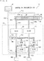
- Fig. 5 is a schematic diagram showing an operation of the brake device 5 during the control OFF.
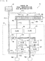
- Fig. 6 is a schematic diagram showing a pressurizing operation of the brake device 5 during the control ON
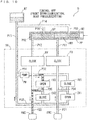
- Fig. 7 is a schematic diagram showing a depressurizing operation of the brake device 5 during the control ON
- Fig. 8 is a schematic diagram showing a retaining operation of the brake device 5 during the control ON.
- Fig. 9 is a schematic diagram showing the pressurizing operation and the depressurizing operation of the brake device 5 during the control ON
- Fig. 10 is a schematic diagram showing the pressurizing operation and the depressurizing operation of the brake device 5 during the control ON.
- the inside of the oil pressure pipes P11 to P16, P21, P22, P31 to P35 is filled with a brake oil.
- the front master cut valve FV and the rear master cut valve RV of the oil pressure unit 56 are opened, and the pressurization valves IV1, IV2 and the depressurization valves DV1, DV2 are closed. Further, the pump PM does not operate.
- the primary piston PP and the secondary piston SP in the tandem master cylinder MC are moved in the axis direction as indicated by an arrow. Thus, openings at the ends of the oil pressure pipes P15, P16 are closed, and the brake oils in the first pressure chamber PR1 and the second pressure chamber PR2 are pressurized.
- the oil pressure pressurized in the first pressure chamber PR1 of the tandem master cylinder MC is directly supplied to the front wheel cylinder FWC via the oil pressure pipe P11, the front master cut valve FV and the oil pressure pipe P21.
- the oil pressure pressurized in the second pressure chamber PR2 of the tandem master cylinder MC is directly supplied to the rear wheel cylinder RWC via the oil pressure pipe P12, the rear master cut valve RV and the oil pressure pipe P22.
- the braking forces corresponding to the operation amount of the brake lever 54 are respectively exerted on the front wheel 3 and the rear wheel 4.
- the pressurization valves IV1, IV2 are opened, and the depressurization valves DV1, DV2 are closed.
- the pump PM operates.
- the oil pressure pressurized by the pump PM is respectively supplied to the front wheel cylinder FWC and the rear wheel cylinder RWC via the oil pressure pipe P31, the oil pressure pipe P32, the pressurization valves IV1, IV2, the oil pressure pipes P34, P35 and the oil pressure pipes P21, P22.
- the pressurization valves IV1, IV2 are closed, and the depressurization valves DV1, DV2 are opened.
- the pump PM does not operate.
- the oil pressure in the front wheel cylinder FWC and the oil pressure in the rear wheel cylinder in RWC are decreased via the oil pressure pipes P21, P22, the oil pressure pipes P34, P35, the depressurization valves DV1, DV2, the oil pressure pipe P33, and the oil pressure pipe P13.
- the pressurization valve IV1 and the depressurization valve DV2 are opened, and the pressurization valve IV2 and the depressurization valve DV1 are closed.
- the pump PM operates.
- the oil pressure pressurized by the pump PM is supplied to the front wheel cylinder FWC via the oil pressure pipe P32, the pressurization valve IV1, the oil pressure pipe P34, and the oil pressure pipe P21.
- the oil pressure in the rear wheel cylinder RWC is reduced via the oil pressure pipe P22, the oil pressure pipe P35, the depressurization valve DV2, the oil pressure pipe P33, and the oil pressure pipe P13.
- the oil pressure in the front wheel cylinder FWC is increased, and the oil pressure in the rear wheel cylinder RWC is decreased.
- the pressurization valve IV2 and the depressurization valve DV1 are opened, and the pressurization valve IV1 and the depressurization valve DV2 are closed.
- the pump PM operates.
- the oil pressure in the front wheel cylinder FWC is decreased via the oil pressure pipe P21, the oil pressure pipe P34, the depressurization valve DV1, the oil pressure pipe P33 and the oil pressure pipe P13.
- the brake oil pressurized by the pump PM is supplied to the rear wheel cylinder RWC via the oil pressure pipe P32, the pressurization valve IV2, the oil pressure pipe P35 and the oil pressure pipe P22.
- the oil pressure in the front wheel cylinder FWC is decreased, and the oil pressure in the rear wheel cylinder RWC is increased.
- Fig. 11 is a diagram showing a first example of the operation amount-front/rear wheel target braking force characteristics.
- Fig. 12 is a diagram showing a second example of the operation amount-front/rear wheel target braking force characteristics.
- the operation amount-front/rear wheel target braking force characteristics shows a relationship between the operation amount of the brake lever 54 by the driver and the braking force to be exerted on the front wheel 3, and a relationship between the operation amount of the brake lever 54 by the driver and the braking force to be exerted on the rear wheel 4.
- the braking force to be exerted on the front wheel 3 is referred to as a front wheel target braking force
- the braking force to be exerted on the rear wheel 4 is referred to as a rear wheel target braking force.
- Figs. 11 and 12 indicate the operation amount [MPa] of the brake lever 54, and the ordinates indicate the front wheel target braking force [N] and the rear wheel target braking force [N].
- the braking force is distributed to the front wheel 3 and the rear wheel 4 such that the rear wheel target braking force is larger than the front wheel target braking force.
- the braking force is distributed to the front wheel 3 and the rear wheel 4 such that the front wheel target braking force is larger than the rear wheel target braking force.
- the operation amount-front/rear wheel target braking force characteristics of Fig. 11 is equivalent to a general ideal braking force distribution line.
- the ideal braking force distribution line is a distribution method by which the front wheel 3 and the rear wheel 4 are simultaneously locked in a condition of the road surface in which a braking force that can be generated during the traveling of the motorcycle 1 in a straight line is at a maximum.
- the braking force is distributed to the front wheel 3 and the rear wheel 4 based on the ideal braking force distribution line, whereby deceleration of the motorcycle 1 can be sufficiently ensured.
- the braking force is distributed to the front wheel 3 and the rear wheel 4 such that the rear wheel target braking force is larger than the front wheel target braking force.
- the operation amount-front/rear wheel target braking force characteristics of Fig. 12 represents braking force distribution characteristics having importance on the rear wheel.
- the operation amount-front/rear wheel target braking force characteristics having importance on the front wheel may be used.
- Braking of the straddled vehicle, such as a motorcycle is more likely to be influenced by a condition of a loaded object than a four-wheeled automobile.
- the operation amount-front/rear wheel target braking force characteristics having importance on the front wheel is used, whereby distribution of the braking force is optimal.
- the operation amount-front/rear wheel target braking force characteristics having an importance on the rear wheel is used, whereby distribution of the braking force is optimal.
- the operation amount-front/rear wheel target braking force characteristics having importance on the front wheel can be used.
- the operation amount-front/rear wheel target braking force having importance on the rear wheel can be used.
- the driver can select any one of a plurality of operation amount-front/rear wheel target braking force characteristics using the characteristics switching switch SW of Fig. 2 .
- distribution of the braking force to the front wheel 3 and the rear wheel 4 can be changed according to each type of a condition such as a state of a loaded object or a driving method. As a result, braking to the satisfaction of the driver is possible.
- Fig. 13 is a diagram showing an example of the operation amount-both wheels target braking force characteristics in the present embodiment.
- the operation amount-both wheels target braking force characteristics shows a relationship between the operation amount of the brake lever 54 by the driver and the total of the braking forces to be exerted on the front wheel 3 and the rear wheel 4.
- the total of the braking forces to be exerted on the front wheel 3 and the rear wheel 4 is referred to as a both wheels target braking force.
- Fig. 13 indicates the operation amount [MPa] of the brake lever 54, and the ordinate indicates the both wheels target braking force [N]. This also applies to Fig. 15 , described below.
- the operation amount-front/rear wheel target braking force characteristics of Figs. 11 and 12 is set such that the operation amount-both wheels target braking force characteristics in the case where the brake control device 53 is in the control ON state is equal to the operation amount-both wheels target braking force characteristics in the case where the brake control device 53 is in the control OFF state.
- the total of the braking forces respectively exerted on the front wheel 3 and the rear wheel 4 in the control ON state is equal to the total of the braking forces exerted on the front wheel 3 and the rear wheel 4 in the control OFF state.
- the total of the braking forces exerted on the front wheel 3 and the rear wheel 4 in the control OFF state (the both wheels braking force) can be found from the following arithmetic formula.
- the both wheels braking force a master cylinder pressure x ⁇ (a front wheel cylinder area x a friction coefficient of a front wheel brake pad x the number of front wheel disc rotors x an effective radius of the front wheel disc rotor / an effective radius of a front wheel tire) + (a rear wheel cylinder area x a friction coefficient of a rear wheel brake pad x the number of rear wheel disc rotors x an effective radius of the rear wheel disc rotor / an effective radius of a rear wheel tire) ⁇
- the master cylinder pressure is the pressure detected by the master pressure sensor MS. From the above formula, the both wheels braking force corresponding to the master cylinder pressure is calculated. Therefore, a relationship between the operation amount of the brake lever 54 and the both wheels target braking force (the operation amount-the both wheels target braking force characteristics) can be found in advance.
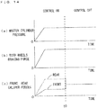
- Fig. 14 is a diagram for explaining changes in braking force when the control ON state and the control OFF state are switched with each other in the embodiment.
- Fig. 14(a) shows a change in master cylinder pressure
- Fig. 14(b) shows a change in total of the braking forces exerted on the front wheel 3 and the rear wheel 4 (the both wheels braking force)
- Fig. 14(c) shows changes in front caliper pressure and rear caliper pressure.
- the abscissas of the Figs. 14(a) to 14(c) indicate time.
- the master cylinder pressure corresponds to the operation amount of the brake lever 54.
- the front caliper pressure is the pressure detected by the front caliper pressure sensor FS
- the rear caliper pressure is the pressure detected by the rear caliper pressure sensor RS.
- Fig. 14(a) when the master cylinder pressure is increased from 0 in the control ON state, the front caliper pressure and the rear caliper pressure are increased as shown in Fig. 14(c) .
- the rear caliper pressure is larger than the front caliper pressure.
- the both wheels braking force is also increased.
- the master cylinder pressure becomes constant, the front caliper pressure and the rear caliper pressure become constant at different magnitudes, and the both wheels braking force also becomes constant.
- Fig. 15 is a diagram showing an example of the operation amount-both wheels target braking force characteristics in the comparative example.
- the operation amount-both wheels target braking force characteristics in the case where the brake control device 53 is in the control ON state and the operation amount-both wheels target braking force characteristics in the case where the brake control device 53 is in the control OFF state are different from each other.
- pressurization by the pump PM is performed. Therefore, in the comparative example, the both wheels braking force in the control ON state is generally larger than the both wheels braking force in the control OFF state.
- Fig. 16 is a diagram for explaining changes in braking force when the control ON state and the control OFF state are switched with each other in the comparative example.
- Fig. 16(a) shows a change in master cylinder pressure
- Fig. 16(b) shows a change in total of the braking forces exerted on the front wheel 3 and the rear wheel 4 (the both wheels braking force)
- Fig. 16(c) shows a change in front caliper pressure and rear caliper pressure.
- the front caliper pressure and the rear caliper pressure in the control ON state of the comparative example shown in Fig. 16(c) are respectively larger than the front caliper pressure and the rear caliper pressure in the control ON state of the embodiment shown in Fig. 14(c) .
- the both wheels braking force in the control OFF state becomes smaller than the both wheels braking force in the control ON state as shown in Fig. 16(b) .
- an uncomfortable feeling is supplied to the driver.
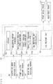
- Fig. 17 is a block diagram mainly showing the configuration of the control system of the brake device 5 of Fig. 3 .
- the ECU 55 of the brake control device 53 includes a storage 551, an operation amount acquirer 552, a both wheels braking force acquirer 553, a target braking force acquirer 554, a target oil pressure calculator 555 and an oil pressure unit controller 556.
- the storage 551 stores a control program, the operation amount-front/rear wheel target braking force characteristics of Figs. 11 and 12 , the operation amount-both wheels target braking force characteristics of Fig. 13 , and various data.
- the ECU 55 has a CPU (a Central Processing Unit) and a ROM (a Read Only Memory) and a storage device such as a RAM (a Random Access Memory).
- the CPU that functions as the storage 551 executes the control program, so that the functions of the operation amount acquirer 552, the both wheels braking force acquirer 553, the target braking force acquirer 554, the target oil pressure calculator 555 and the oil pressure unit controller 556 are realized.
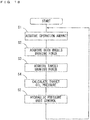
- Fig. 18 is a flow chart showing an operation of the brake device 5 of Fig. 17 during the control ON.
- the operation amount acquirer 552 acquires the operation amount of the brake lever 54 based on the master cylinder pressure detected by the master pressure sensor MS (step S1).
- the operation amount acquirer 552 converts a voltage output from the master pressure sensor MS into an oil pressure, and acquires the oil pressure as the operation amount.
- the both wheels braking force acquirer 553 acquires the both wheels target braking force corresponding to the operation amount from the operation amount-both wheels target braking force characteristics stored in the storage 551 (step S2).
- the target braking force acquirer 554 respectively acquires the front wheel target braking force and the rear wheel target braking force corresponding to the operation amount from the operation amount-front/rear wheel target braking force characteristics stored in the storage 551 (step S3). At this time, the front wheel target braking force and the rear wheel target braking force are corrected such that the total of the front wheel target braking force and the rear wheel target braking force corresponding to the operation amount is equal to the both wheels target braking force acquired in the step S2.
- the operation amount-front/rear wheel target braking force characteristics may be set in advance such that the operation amount-both wheels target braking force characteristics in the control ON state is equal to the operation amount-both wheels target braking force characteristics in the control OFF state. In this case, the process of the step S2 does not have to be performed.
- the target oil pressure calculator 555 calculates the oil pressures corresponding to the acquired front wheel target braking force and rear wheel target braking force (step S4).
- the target front caliper pressure the front wheel target braking force / (a front wheel cylinder area x a friction coefficient of a front wheel brake pad x the number of front wheel disc rotors x an effective radius of the front disc rotors / an effective radius of a front wheel tire)
- the target rear caliper pressure the rear wheel target braking force / (a rear wheel cylinder area x a friction coefficient of a rear wheel brake pad x the number of rear wheel disc rotors x an effective radius of the rear wheel disc rotors / an effective radius of a rear wheel tire)
- the oil pressure unit controller 556 controls the oil pressure unit 56 such that the oil pressure corresponding to the front wheel target braking force (the target front caliper pressure) is supplied to the front wheel cylinder FWC, and the oil pressure corresponding to the rear wheel target braking force (the target rear caliper pressure) is supplied to the rear wheel cylinder RWC (step S5).
- the oil pressure unit controller 556 controls the opening and closing of the pressurization valves IV1, IV2 and the depressurization valves DV1, DV2 based on the pressures detected by the front caliper pressure sensor FS and the rear caliper pressure sensor RS of Fig. 3 .
- the operation amount of the brake lever 54 by the driver is detected by the master pressure sensor MS.
- the front wheel target braking force and the rear wheel target braking force are acquired from the operation amount-front and rear wheel target braking force characteristics based on the operation amount detected by the master pressure sensor MS.
- the oil pressure corresponding to the front wheel target braking force is supplied to the front wheel brake 51, and the oil pressure corresponding to the rear wheel target braking force is supplied to the second brake.
- the braking forces appropriately corresponding to the operation amount can be respectively distributed to the front wheel 3 and the rear wheel 4 by operating the brake lever 54, which is a single operation member, by the driver.
- the brake control device 53 enters the control OFF state, and the hydraulic pressure control is not performed.
- the oil pressures corresponding to the operation amount of the brake lever 54 by the driver are directly supplied from the tandem master cylinder MC to the front wheel brake 51 and the rear wheel brake 52.
- the driver can manually adjust the braking forces exerted on the front wheel 3 and the rear wheel 4 by operating the brake lever 54, which is a single operation member.
- the hydraulic pressure control by the brake control device 53 is performed such that the relationship between the operation amount of the brake lever 54 and the total of the braking forces exerted on the front wheel 3 and the rear wheel 4 during the control ON of the brake control device 53 is equal to the relationship between the operation amount of the brake lever 54 and the total of the braking forces exerted on the front wheel 3 and the rear wheel 4 during the control OFF of the brake control device 53.
- the control ON state and the control OFF state of the brake control device 53 are switched with each other, a rapid change in braking force does not occur, so that stable deceleration is performed without an uncomfortable feeling being supplied to the driver.
- a load applied in the braking operation by the driver can be reduced, and comfort during the braking operation can be improved.
- the brake lever 54 is provided in the vicinity of the left end of the handlebar 71 as a single operation member in the above-mentioned embodiment, the arrangement of a single operation member is not limited to this.
- Fig. 19 is a plan view showing another example of the handle 7.
- the accelerator grip 72 is provided at the right end of the handlebar 71.
- the tandem master cylinder MC is provided at the center of the right half portion of the handlebar 71.
- the brake lever 54 is provided at the center of the right half portion of the handlebar 71 to extend to a position in the vicinity of the right end.
- the reserve tank RT (not shown) is attached to the upper surface of the tandem master cylinder MC.
- the switch box 73 is attached to a position between the accelerator grip 72 and the tandem master cylinder MC.
- the characteristics switching switch SW is provided at the switch box 73.
- the switch box 74 is attached to the center of the left half portion of the handlebar 71. Further, the clutch lever 75 is provided at the center of the left half portion of the handlebar 71 to extend to a position in the vicinity of the left end.
- the characteristics switching switch SW may be provided at the switch box 74.
- the handle 7 of Fig. 19 is provided at the motorcycle including a manual transmission.
- the driver adjusts the output of the engine 6 by operating the accelerator grip 72 with his or her right hand, and performs disconnection and connection of the clutch by operating the clutch lever 75 with his or her left hand.
- the driver operates the brake lever 54 with his or her right hand.
- the brake lever 54 that is a single operation member is provided on the opposite side of the clutch lever 75.
- the driver can simultaneously and independently perform the adjustment of the braking forces and the adjustment of disconnection and connection of the driving forces for the front wheel 3 and the rear wheel 4 with different hands during starting on the ramp. Therefore, good driving operability during the stop, and before and after the starting of the motorcycle 1 can be ensured.
- Fig. 20 is a schematic plan view showing an example of another motorcycle to which the present invention is applied.
- Fig. 21 is a schematic side view of the motorcycle of Fig. 20 .
- the motorcycle 1A of Figs. 20 and 21 is an American (cruiser) type motorcycle.
- the switch box 73 is attached to the center of the right half portion of the handlebar 71 of the handle 7, and the switch box 74 is attached to the center of the left half portion of the handlebar 71.
- the clutch bar 75 is provided at the center of the left half portion of the handlebar 71 to extend to a position in the vicinity of the left end.
- footrests 76, 77 on which the driver puts his or her feet are provided at lower portions on both sides of the vehicle main body 2.
- a brake pedal 54a is provided in front of the footrest 76 on the right side of the vehicle main body 2.
- the tandem master cylinder MC is attached to a position in the vicinity of the brake pedal 54a on the right side of the vehicle main body 2.
- a shift pedal 78 for transmission is provided in front of the footrest 77 on the left side of the vehicle main body 2.
- a top portion of a tread surface of the brake pedal 54a is located above a top portion of a tread surface of the footrest 76.
- a top portion of a tread surface of the shift pedal 78 is located above a top portion of a tread surface of the footrest 77.
- the driver adjusts the output of the engine 6 by operating the accelerator grip 72 with his or her right hand, and performs disconnection and connection of the clutch by operating the clutch lever 75 with his or her left hand. Further, the driver operates the brake pedal 54a with the right foot put on the right footrest 76, and operates the shift pedal 78 with the left foot put on the left footrest 77. Thus, a driving operation becomes easy. Further, even with an inertial force being added to the feet by braking of the front wheel 3 and the rear wheel 4, a tread force of the brake pedal 54a can be delicately and easily adjusted while the inertial force is received by the footrest 76.
- Fig. 22 is a plan view showing yet another example of the handle 7.
- a thumb lever type accelerator lever 72a is provided in the vicinity of the right end of the handlebar 71.
- Other parts of the handle 7 of Fig. 22 are similar to the parts corresponding to the handle 7 of Fig. 2 .
- the handle 7 of Fig. 22 is provided at a buggy type four-wheeled automobile (an ATV (an All Terrain Vehicle)), for example.
- ATV an All Terrain Vehicle
- the driver adjusts the output of the engine 6 by pressing the accelerator lever 72 forward with his or her right thumb, and operates the brake lever 54 with his or her left hand.
- the brake lever 54 which is a single operation member, is provided on the opposite side of the thumb lever type accelerator lever 72a.
- the driver can simultaneously and independently perform the adjustment of the braking forces and the adjustment of the driving forces for the front wheel 3 and the rear wheel 4. Therefore, good driving operability during the acceleration and deceleration of the straddled vehicle can be ensured, and the behavior and speed of the straddled vehicle can be easily adjusted.
- the one end of the handlebar 71 can be easily held by a thumb and a plurality of other fingers at all times, so that steerability, and maintenance of the upper body can be enhanced.
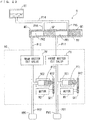
- Fig. 23 is a schematic diagram mainly showing an example of another configuration of the oil pressure unit 56 of the brake device 5.
- the oil pressure unit 56 of Fig. 23 includes a front master cut valve FV, a rear master cut valve RV, sub-cylinders SC1, SC2, motors M1, M2 and gears G11, G12, G21, G22.
- pistons PT1, PT2 are provided to be respectively movable in the axis direction.
- the gears G11, G12 are rotated.
- the piston PT1 is moved in the axis direction in the sub-cylinder SC1.
- the gears G21, G22 are rotated.
- the piston PT2 is moved in the axis direction in the sub-cylinder SC2.
- the front master cut valve FV and the rear master cut valve RV of the oil pressure unit 56 are opened, and the motors M1, M2 do not operate.
- the oil pressure in the first pressure chamber PR1 of the tandem master cylinder MC is directly supplied to the front wheel cylinder FWC via the oil pressure pipe P11, the front master cut valve FV and the oil pressure pipe P21.
- the oil pressure in the second pressure chamber PR2 of the tandem master cylinder MC is directly supplied to the rear wheel cylinder RWC via the oil pressure pipe P12, the rear master cut valve RV and the oil pressure pipe P22.
- the braking forces corresponding to the operation amount of the brake lever 54 are respectively exerted on the front wheel 3 and the rear wheel 4.
- the front master cut valve FV and the rear master cut valve RV are opened.
- the piston PT1 is moved in one direction (the leftward direction of the diagram) in the sub-cylinder SC1.
- the oil pressure supplied to the front wheel cylinder FWC is increased.
- the piston PT1 is moved in another direction (the rightward direction of the diagram) in the sub-cylinder SC1.
- the oil pressure supplied to the front wheel cylinder FWC is decreased.
- the piston PT2 is moved in one or the other direction in the sub-cylinder SC2.
- the oil pressure supplied to the rear wheel cylinder RWC is increased or decreased. In this manner, the braking forces exerted on the front wheel 3 and the rear wheel 4 are respectively adjusted by the operations of the motors M1, M2.
- the configuration of the oil pressure unit 56 is not limited to the configurations of the Figs. 5 and 23 .
- a first three-way valve may be connected to a position between the oil pressure pipe P11 and the oil pressure pipe P21
- a second three-way valve may be connected to a position between the oil pressure pipe P12 and the oil pressure pipe P22
- an oil pressure adjustment unit that adjusts the oil pressure may be connected to the first and second three-way valves.
- the operation amount detector is not limited to this.
- Various types of sensors such as a stroke sensor that can detect a movement amount of an operation member, can be used as the operation amount detector.
- the straddled vehicle according to the present invention is not limited to a vehicle that travels while a rider is straddling a seat, but includes a vehicle in which the rider can be seated with both of her or his feet put together. That is, the straddled vehicle according to the present invention includes various types of vehicles that can turn while the vehicle bodies are tilted.
- the present invention is not limited to this.
- the present invention can be applied to another straddled vehicle such as an electric bicycle, a motor tricycle, a buggy type four-wheeled automobile or a snow mobile.
- the brake device 5 is an example of a brake device
- the front wheel brake 51 and the rear wheel brake 52 are respectively examples of first and second brakes
- the brake lever 54 or the brake pedal 54a are examples of a single operation member.
- the master pressure sensor MS is an example of an operation amount detector
- the storage 551 is an example of a storage
- the brake control device 53 is an example of a hydraulic pressure control device
- the tandem master cylinder MC is an example of a hydraulic pressure generation device.
- the oil pressure is an example of a hydraulic pressure
- the front wheel target braking force and the rear wheel target braking force are respectively examples of first and second target braking forces
- the operation amount-front/rear wheel target braking force characteristics is an example of a relationship between an operation amount of an operation member and braking forces respectively exerted on a front wheel and a rear wheel
- during control OFF is an example of during a non-operation of hydraulic pressure control
- the control ON is an example of during an operation of hydraulic pressure control.
- the front wheel cylinder FWC and the rear wheel cylinder RWC are respectively examples of first and second cylinders
- the tandem master cylinder MC is an example of a master cylinder
- the first pressure chamber PR1 and the second pressure chamber PR2 are examples of first and second pressure chambers
- the characteristics switching switch SW is an example of a selector.
- the handle 7 is an example of a handle
- the handlebar 71 is an example of a handlebar
- the accelerator grip 72 is an example of an accelerator grip
- the clutch lever 75 is an example of a clutch lever
- the footrests 76, 77 are examples of first and second footrests
- the shift pedal 78 is an example of a shift pedal
- the accelerator lever 72a is an example of a thumb lever type accelerator lever.
- the vehicle main body 2 is an example of a main body
- the engine 6 or the electric motor is an example of a motor.
- the present invention can be utilized for the braking of various types of straddled vehicles.
Landscapes
- Engineering & Computer Science (AREA)
- Mechanical Engineering (AREA)
- Transportation (AREA)
- Regulating Braking Force (AREA)
- Hydraulic Control Valves For Brake Systems (AREA)
Claims (8)
- Eine Bremsvorrichtung (5) für ein rittlings zu fahrendes Fahrzeug (1) mit einem Vorderrad (3) und einem Hinterrad (4), wobei die Bremsvorrichtung folgende Merkmale aufweist:eine erste Bremse (51), die dazu konfiguriert ist, durch einen Hydraulikdruck eine Bremskraft auf das Vorderrad (3) auszuüben;eine zweite Bremse (52), die dazu konfiguriert ist, durch einen Hydraulikdruck eine Bremskraft auf das Hinterrad (4) auszuüben;ein Betätigungsbauglied (54, 54a), das dazu konfiguriert ist, durch einen Fahrer betätigt zu werden, um die Bremskräfte der ersten und der zweiten Bremse (51, 52) einzustellen;einen Betätigungsbetragdetektor (MS), der dazu konfiguriert ist, einen Betätigungsbetrag des Betätigungsbauglieds (54, 54a) zu erfassen;einen Speicher (551), der dazu konfiguriert ist, eine Beziehung zwischen einem Betätigungsbetrag des Betätigungsbauglieds (54, 54a) und Bremskräften zu speichern, die jeweils auf das Vorderrad (3) und das Hinterrad (4) ausgeübt werden sollen;eine Hydraulikdruck-Steuervorrichtung (53), die dazu konfiguriert ist, eine Hydraulikdrucksteuerung durchzuführen, um von der Beziehung, die in dem Speicher (551) gespeichert ist, auf Basis des Betätigungsbetrags, der durch den Betätigungsbetragdetektor (MS) erfasst wird, eine Bremskraft, die auf das Vorderrad (3) ausgeübt werden soll, als eine erste Zielbremskraft und eine Bremskraft, die auf das Hinterrad (4) ausgeübt werden soll, als eine zweite Zielbremskraft zu erhalten, um einen Hydraulikdruck, der der erhaltenen ersten Zielbremskraft entspricht, der ersten Bremse (51) zuzuführen und um einen Hydraulikdruck, der der erhaltenen zweiten Zielbremskraft entspricht, der zweiten Bremse (52) zuzuführen;dadurch gekennzeichnet, dass das Betätigungsbauglied ein einzelnes Betätigungsbauglied (54, 54a) aufweist, undeine Hydraulikdruck-Erzeugungsvorrichtung (MC), die dazu konfiguriert ist, Hydraulikdrücke, die dem Betätigungsbetrag des einzelnen Betätigungsbauglieds (54, 54a) entsprechen, während einer Nichtbetätigung der Hydraulikdrucksteuerung der Hydraulikdruck-Steuervorrichtung (53) jeweils der ersten Bremse (51) und der zweiten Bremse (52) zuzuführen,wobei die Hydraulikdruck-Steuervorrichtung (53) dazu konfiguriert ist, die Hydraulikdrucksteuerung derart durchzuführen, dass eine Beziehung zwischen einem Betätigungsbetrag des einzelnen Betätigungsbauglieds (54, 54a) und einem Gesamtbetrag der Bremskräfte, die während einer Betätigung der Hydraulikdrucksteuerung auf das Vorderrad (3) und auf das Hinterrad (4) ausgeübt werden, gleich einer Beziehung zwischen einem Betätigungsbetrag des einzelnen Betätigungsbauglieds (54, 54a) und einem Gesamtbetrag der Bremskräfte ist, die während der Nichtbetätigung der Hydraulikdrucksteuerung auf das Vorderrad (3) und auf das Hinterrad (4) ausgeübt werden.
- Die Bremsvorrichtung (5) gemäß Anspruch 1, bei der
die erste Bremse (51) einen ersten Zylinder (FWC) umfasst, der dazu konfiguriert ist, durch einen Hydraulikdruck eine Bremskraft auf das Vorderrad (3) auszuüben,
die zweite Bremse (52) einen zweiten Zylinder (RWC) umfasst, der dazu konfiguriert ist, durch einen Hydraulikdruck eine Bremskraft auf das Hinterrad (4) auszuüben,
die Hydraulikdruck-Erzeugungsvorrichtung (MC) einen Tandemmasterzylinder mit einer ersten und einer zweiten Druckkammer (PR1, PR2) umfasst, die dazu konfiguriert sind, jeweils die Hydraulikdrücke zu erzeugen, die dem Betätigungsbetrag des einzelnen Betätigungsbauglieds (54, 54a) entsprechen, und
der Hydraulikdruck, der durch die erste Druckkammer (PR1) erzeugt wird, dem ersten Zylinder (FWC) zugeführt wird, und der Hydraulikdruck, der durch die zweite Druckkammer (PR2) erzeugt wird, dem zweiten Zylinder (RWC) zugeführt wird. - Die Bremsvorrichtung (5) gemäß Anspruch 1 oder 2, bei der
der Speicher (551) dazu konfiguriert ist, eine Mehrzahl von Beziehungen zu speichern,
die Bremsvorrichtung (5) ferner einen Selektor (SW) aufweist, der dazu konfiguriert ist, eine Beziehung aus der Mehrzahl von Beziehungen auszuwählen, und
die Hydraulikdruck-Steuervorrichtung (53) dazu konfiguriert ist, die erste beziehungsweise die zweite Zielbremskraft von der Beziehung zu erhalten, die durch den Selektor (SW) auf Basis des durch den Betätigungsbetragdetektor (MS) erfassten Betätigungsbetrags ausgewählt wird. - Ein rittlings zu fahrendes Fahrzeug, das eine Bremsvorrichtung (5) gemäß einem der Ansprüche 1 bis 3 aufweist, wobei
das rittlings zu fahrende Fahrzeug (1) einen Motor (6), einen Lenker (71) und einen Beschleunigungsgriff (72) aufweist, der an einem Ende des Lenkers (71) vorgesehen ist und dazu konfiguriert ist, eine Ausgabe des Motors (6) einzustellen, wobei das rittlings zu fahrende Fahrzeug (1) dazu konfiguriert ist, eine Ausgabe des Motors (6) an das Vorderrad (3) und/oder das Hinterrad (4) über ein automatisches Getriebe oder direkt zu übertragen, und
das einzelne Betätigungsbauglied (54) einen Bremshebel umfasst, der an einem Abschnitt des Lenkers (71) auf einer gegenüberliegenden Seite des Beschleunigungsgriffs (72) vorgesehen ist. - Ein rittlings zu fahrendes Fahrzeug, das eine Bremsvorrichtung (5) gemäß einem der Ansprüche 1 bis 3 aufweist, wobei
das rittlings zu fahrende Fahrzeug (1) einen Motor (6), einen Lenker (71), einen Beschleunigungsgriff (72), der an einem Ende des Lenkers (71) vorgesehen ist und dazu konfiguriert ist, eine Ausgabe des Motors (6) einzustellen, und einen Kupplungshebel (75) aufweist, der an einem Abschnitt des Lenkers (71) auf einer gegenüberliegenden Seite des Beschleunigungsgriffs (72) vorgesehen ist, und
das einzelne Betätigungsbauglied (54) einen Bremshebel umfasst, der auf einer selben Seite wie der Beschleunigungsgriff (72) des Lenkers (71) vorgesehen ist. - Ein rittlings zu fahrendes Fahrzeug, das eine Bremsvorrichtung (5) gemäß einem der Ansprüche 1 bis 3 aufweist, wobei
das rittlings zu fahrende Fahrzeug (1) einen Motor (6), einen Lenker (71), einen Beschleunigungsgriff (72), der an einem Ende des Lenkers (71) vorgesehen und dazu konfiguriert ist, eine Ausgabe des Motors (6) einzustellen, eine erste und eine zweite Fußraste (76, 77), auf denen die Füße des Fahrers abgestellt werden können, und ein Schaltpedal aufweist, das dahingehend vorgesehen ist, durch einen auf der ersten Fußraste (76) abgestellten Fuß betätigt zu werden, und
das einzelne Betätigungsbauglied (54a) ein Bremspedal umfasst, das dahingehend vorgesehen ist, durch einen anderen auf der zweiten Fußraste (77) abgestellten Fuß betätigt zu werden. - Ein rittlings zu fahrendes Fahrzeug, das eine Bremsvorrichtung (5) gemäß einem der Ansprüche 1 bis 3 aufweist, wobei
das rittlings zu fahrende Fahrzeug (1) einen Motor (6), einen Lenker (71) und einen Daumenhebeltyp-Beschleunigungshebel (72a) aufweist, der an einem Ende des Lenkers (71) vorgesehen und dazu konfiguriert ist, eine Ausgabe des Motors (6) einzustellen, und
das einzelne Betätigungsbauglied (54) einen Bremshebel umfasst, der an einem Abschnitt des Lenkers (71) auf einer gegenüberliegenden Seite des Daumenhebeltyp-Beschleunigungshebels (72a) vorgesehen ist. - Ein rittlings zu fahrendes Fahrzeug (1), das folgende Merkmale aufweist:einen Körper (2);ein Vorderrad (3), das an dem Körper (2) dahingehend vorgesehen ist, drehbar zu sein;ein Hinterrad (4), das an dem Körper (2) dahingehend vorgesehen ist, drehbar zu sein;einen Motor (6), der dazu konfiguriert ist, eine Ausgabe zum Drehen des Vorderrads (3) und/oder des Hinterrads (4) zu erzeugen; undeine Bremsvorrichtung (5) gemäß einem der Ansprüche 1 bis 7 zum Bremsen des Vorderrads (3) und des Hinterrads (4).
Applications Claiming Priority (2)
| Application Number | Priority Date | Filing Date | Title |
|---|---|---|---|
| JP2013247335 | 2013-11-29 | ||
| PCT/JP2014/005140 WO2015079611A1 (ja) | 2013-11-29 | 2014-10-09 | ブレーキ装置および鞍乗り型車両 |
Publications (3)
| Publication Number | Publication Date |
|---|---|
| EP3078582A1 EP3078582A1 (de) | 2016-10-12 |
| EP3078582A4 EP3078582A4 (de) | 2017-12-27 |
| EP3078582B1 true EP3078582B1 (de) | 2019-04-24 |
Family
ID=53198591
Family Applications (1)
| Application Number | Title | Priority Date | Filing Date |
|---|---|---|---|
| EP14866709.0A Active EP3078582B1 (de) | 2013-11-29 | 2014-10-09 | Bremsvorrichtung und grätschsitzfahrzeug |
Country Status (3)
| Country | Link |
|---|---|
| US (1) | US20170021895A1 (de) |
| EP (1) | EP3078582B1 (de) |
| WO (1) | WO2015079611A1 (de) |
Families Citing this family (8)
| Publication number | Priority date | Publication date | Assignee | Title |
|---|---|---|---|---|
| JP6634980B2 (ja) * | 2016-07-27 | 2020-01-22 | 株式会社アドヴィックス | 車両の制動制御装置 |
| JP2019026166A (ja) * | 2017-08-02 | 2019-02-21 | ローベルト ボッシュ ゲゼルシャフト ミット ベシュレンクテル ハフツング | 制御装置、車体挙動制御システム、モータサイクル、及び、制御方法 |
| US10676151B2 (en) * | 2017-08-03 | 2020-06-09 | Shimano Inc. | Hydraulic operating device |
| US11021143B2 (en) * | 2018-07-30 | 2021-06-01 | Honda Motor Co., Ltd. | Apparatus, system, and method for use in brake caliper inspection |
| TWI707799B (zh) * | 2020-03-27 | 2020-10-21 | 彥豪金屬工業股份有限公司 | 自行車防鎖死煞車裝置控制方法及自行車防鎖死煞車組件 |
| IT202100011621A1 (it) * | 2021-05-06 | 2022-11-06 | Brembo Spa | Impianto frenante di tipo brake-by-wire per motocicli |
| CN113771809B (zh) * | 2021-09-23 | 2023-04-14 | 摩拜(北京)信息技术有限公司 | 电动自行车的制动控制方法、装置、电子设备和可读介质 |
| IT202100030635A1 (it) * | 2021-12-03 | 2023-06-03 | Brembo Spa | Metodo di controllo di un sistema frenante in tecnologia bbw per la distribuzione di forze frenanti per frenata di servizio di un veicolo |
Family Cites Families (7)
| Publication number | Priority date | Publication date | Assignee | Title |
|---|---|---|---|---|
| DE3302642C2 (de) * | 1983-01-27 | 1986-09-04 | Daimler-Benz Ag, 7000 Stuttgart | Antiblockiersystem für ein Zweirad-Straßenfahrzeug mit hydraulischer Zweikreis-Bremsanlage |
| US6213564B1 (en) * | 1997-04-15 | 2001-04-10 | Face International Corp | Anti-lock brake system with piezoelectric brake actuator |
| JP4526135B2 (ja) | 1999-03-17 | 2010-08-18 | 本田技研工業株式会社 | 自動二輪車の前後輪連動ブレーキ装置 |
| JP2002256904A (ja) * | 2001-02-28 | 2002-09-11 | Mikuni Corp | アクセル操作装置 |
| JP4628805B2 (ja) * | 2004-01-30 | 2011-02-09 | 本田技研工業株式会社 | 自動二輪車のブレーキ装置 |
| JP4536389B2 (ja) * | 2004-01-30 | 2010-09-01 | 本田技研工業株式会社 | 自動二輪車のブレーキ装置 |
| JP2009058123A (ja) * | 2007-08-08 | 2009-03-19 | Yamaha Motor Co Ltd | 自動二輪車 |
-
2014
- 2014-10-09 EP EP14866709.0A patent/EP3078582B1/de active Active
- 2014-10-09 US US15/100,141 patent/US20170021895A1/en not_active Abandoned
- 2014-10-09 WO PCT/JP2014/005140 patent/WO2015079611A1/ja not_active Ceased
Non-Patent Citations (1)
| Title |
|---|
| None * |
Also Published As
| Publication number | Publication date |
|---|---|
| WO2015079611A1 (ja) | 2015-06-04 |
| US20170021895A1 (en) | 2017-01-26 |
| EP3078582A1 (de) | 2016-10-12 |
| EP3078582A4 (de) | 2017-12-27 |
Similar Documents
| Publication | Publication Date | Title |
|---|---|---|
| EP3078582A1 (de) | Bremsvorrichtung und grätschsitzfahrzeug | |
| EP2024206B1 (de) | Hand- und fussgesteuertes einzelanwendungs-bremssystem für ein geländefahrzeug | |
| JP6588981B2 (ja) | 加減速制御装置 | |
| JP7217347B2 (ja) | ブレーキシステム、制動力配分装置および電動ブレーキ装置 | |
| JP4526135B2 (ja) | 自動二輪車の前後輪連動ブレーキ装置 | |
| EP2682334B1 (de) | Grätschsitzfahrzeug-Bremssystem und Grätschsitzfahrzeug | |
| JP5386042B2 (ja) | 車両用ブレーキ装置及び車両用ブレーキ装置の制御方法 | |
| JP6176852B2 (ja) | 車両用後輪リフト傾向判定装置 | |
| JPH07196068A (ja) | 自動2輪車用制動装置 | |
| WO2017168231A1 (en) | Synchronized disc braking system for a two-wheeled vehicle | |
| US20170182986A1 (en) | Method for distributing a brake force, and braking device | |
| JP2006199275A (ja) | 車両用制動装置及び鞍乗型車両 | |
| JP7168684B2 (ja) | 制御装置及び制御方法 | |
| JP5656677B2 (ja) | 自動二輪車用ブレーキ装置 | |
| JPH09254859A (ja) | バーハンドル車両用ブレーキ装置 | |
| JP2009154799A (ja) | 制動装置及び該制動装置を備えた鞍乗型車両 | |
| JP2022062850A (ja) | 制御装置及び制御方法 | |
| JP2022040799A (ja) | 制御装置及び制御方法 | |
| JP2022541443A (ja) | オートバイ制動装置 | |
| EP3378717B1 (de) | Sattelfahrzeug | |
| KR20230122129A (ko) | 안장 탑승형 차량을 위한 브레이크 시스템 및 안장탑승형 차량 | |
| WO2020194351A1 (en) | A saddle type vehicle | |
| US20250010939A1 (en) | Vehicle brake system | |
| JP5158244B2 (ja) | 制動力制御装置 | |
| WO2024013639A1 (ja) | 鞍乗り型車両の制御装置及び制御方法 |
Legal Events
| Date | Code | Title | Description |
|---|---|---|---|
| PUAI | Public reference made under article 153(3) epc to a published international application that has entered the european phase |
Free format text: ORIGINAL CODE: 0009012 |
|
| 17P | Request for examination filed |
Effective date: 20160628 |
|
| AK | Designated contracting states |
Kind code of ref document: A1 Designated state(s): AL AT BE BG CH CY CZ DE DK EE ES FI FR GB GR HR HU IE IS IT LI LT LU LV MC MK MT NL NO PL PT RO RS SE SI SK SM TR |
|
| AX | Request for extension of the european patent |
Extension state: BA ME |
|
| DAX | Request for extension of the european patent (deleted) | ||
| A4 | Supplementary search report drawn up and despatched |
Effective date: 20171123 |
|
| RIC1 | Information provided on ipc code assigned before grant |
Ipc: B62K 11/00 20060101ALI20171117BHEP Ipc: B60L 11/18 20060101ALI20171117BHEP Ipc: B60T 8/17 20060101ALI20171117BHEP Ipc: B62L 3/00 20060101ALI20171117BHEP Ipc: B62L 3/08 20060101AFI20171117BHEP |
|
| GRAP | Despatch of communication of intention to grant a patent |
Free format text: ORIGINAL CODE: EPIDOSNIGR1 |
|
| STAA | Information on the status of an ep patent application or granted ep patent |
Free format text: STATUS: GRANT OF PATENT IS INTENDED |
|
| INTG | Intention to grant announced |
Effective date: 20181115 |
|
| GRAS | Grant fee paid |
Free format text: ORIGINAL CODE: EPIDOSNIGR3 |
|
| GRAA | (expected) grant |
Free format text: ORIGINAL CODE: 0009210 |
|
| STAA | Information on the status of an ep patent application or granted ep patent |
Free format text: STATUS: THE PATENT HAS BEEN GRANTED |
|
| AK | Designated contracting states |
Kind code of ref document: B1 Designated state(s): AL AT BE BG CH CY CZ DE DK EE ES FI FR GB GR HR HU IE IS IT LI LT LU LV MC MK MT NL NO PL PT RO RS SE SI SK SM TR |
|
| REG | Reference to a national code |
Ref country code: GB Ref legal event code: FG4D |
|
| REG | Reference to a national code |
Ref country code: CH Ref legal event code: EP |
|
| REG | Reference to a national code |
Ref country code: AT Ref legal event code: REF Ref document number: 1123817 Country of ref document: AT Kind code of ref document: T Effective date: 20190515 Ref country code: IE Ref legal event code: FG4D |
|
| REG | Reference to a national code |
Ref country code: DE Ref legal event code: R096 Ref document number: 602014045520 Country of ref document: DE |
|
| REG | Reference to a national code |
Ref country code: NL Ref legal event code: MP Effective date: 20190424 |
|
| REG | Reference to a national code |
Ref country code: LT Ref legal event code: MG4D |
|
| PG25 | Lapsed in a contracting state [announced via postgrant information from national office to epo] |
Ref country code: NL Free format text: LAPSE BECAUSE OF FAILURE TO SUBMIT A TRANSLATION OF THE DESCRIPTION OR TO PAY THE FEE WITHIN THE PRESCRIBED TIME-LIMIT Effective date: 20190424 |
|
| PG25 | Lapsed in a contracting state [announced via postgrant information from national office to epo] |
Ref country code: SE Free format text: LAPSE BECAUSE OF FAILURE TO SUBMIT A TRANSLATION OF THE DESCRIPTION OR TO PAY THE FEE WITHIN THE PRESCRIBED TIME-LIMIT Effective date: 20190424 Ref country code: ES Free format text: LAPSE BECAUSE OF FAILURE TO SUBMIT A TRANSLATION OF THE DESCRIPTION OR TO PAY THE FEE WITHIN THE PRESCRIBED TIME-LIMIT Effective date: 20190424 Ref country code: HR Free format text: LAPSE BECAUSE OF FAILURE TO SUBMIT A TRANSLATION OF THE DESCRIPTION OR TO PAY THE FEE WITHIN THE PRESCRIBED TIME-LIMIT Effective date: 20190424 Ref country code: LT Free format text: LAPSE BECAUSE OF FAILURE TO SUBMIT A TRANSLATION OF THE DESCRIPTION OR TO PAY THE FEE WITHIN THE PRESCRIBED TIME-LIMIT Effective date: 20190424 Ref country code: NO Free format text: LAPSE BECAUSE OF FAILURE TO SUBMIT A TRANSLATION OF THE DESCRIPTION OR TO PAY THE FEE WITHIN THE PRESCRIBED TIME-LIMIT Effective date: 20190724 Ref country code: FI Free format text: LAPSE BECAUSE OF FAILURE TO SUBMIT A TRANSLATION OF THE DESCRIPTION OR TO PAY THE FEE WITHIN THE PRESCRIBED TIME-LIMIT Effective date: 20190424 Ref country code: PT Free format text: LAPSE BECAUSE OF FAILURE TO SUBMIT A TRANSLATION OF THE DESCRIPTION OR TO PAY THE FEE WITHIN THE PRESCRIBED TIME-LIMIT Effective date: 20190824 Ref country code: AL Free format text: LAPSE BECAUSE OF FAILURE TO SUBMIT A TRANSLATION OF THE DESCRIPTION OR TO PAY THE FEE WITHIN THE PRESCRIBED TIME-LIMIT Effective date: 20190424 |
|
| PG25 | Lapsed in a contracting state [announced via postgrant information from national office to epo] |
Ref country code: RS Free format text: LAPSE BECAUSE OF FAILURE TO SUBMIT A TRANSLATION OF THE DESCRIPTION OR TO PAY THE FEE WITHIN THE PRESCRIBED TIME-LIMIT Effective date: 20190424 Ref country code: LV Free format text: LAPSE BECAUSE OF FAILURE TO SUBMIT A TRANSLATION OF THE DESCRIPTION OR TO PAY THE FEE WITHIN THE PRESCRIBED TIME-LIMIT Effective date: 20190424 Ref country code: GR Free format text: LAPSE BECAUSE OF FAILURE TO SUBMIT A TRANSLATION OF THE DESCRIPTION OR TO PAY THE FEE WITHIN THE PRESCRIBED TIME-LIMIT Effective date: 20190725 Ref country code: PL Free format text: LAPSE BECAUSE OF FAILURE TO SUBMIT A TRANSLATION OF THE DESCRIPTION OR TO PAY THE FEE WITHIN THE PRESCRIBED TIME-LIMIT Effective date: 20190424 Ref country code: BG Free format text: LAPSE BECAUSE OF FAILURE TO SUBMIT A TRANSLATION OF THE DESCRIPTION OR TO PAY THE FEE WITHIN THE PRESCRIBED TIME-LIMIT Effective date: 20190724 |
|
| REG | Reference to a national code |
Ref country code: AT Ref legal event code: MK05 Ref document number: 1123817 Country of ref document: AT Kind code of ref document: T Effective date: 20190424 |
|
| PG25 | Lapsed in a contracting state [announced via postgrant information from national office to epo] |
Ref country code: IS Free format text: LAPSE BECAUSE OF FAILURE TO SUBMIT A TRANSLATION OF THE DESCRIPTION OR TO PAY THE FEE WITHIN THE PRESCRIBED TIME-LIMIT Effective date: 20190824 |
|
| REG | Reference to a national code |
Ref country code: DE Ref legal event code: R097 Ref document number: 602014045520 Country of ref document: DE |
|
| PG25 | Lapsed in a contracting state [announced via postgrant information from national office to epo] |
Ref country code: AT Free format text: LAPSE BECAUSE OF FAILURE TO SUBMIT A TRANSLATION OF THE DESCRIPTION OR TO PAY THE FEE WITHIN THE PRESCRIBED TIME-LIMIT Effective date: 20190424 Ref country code: RO Free format text: LAPSE BECAUSE OF FAILURE TO SUBMIT A TRANSLATION OF THE DESCRIPTION OR TO PAY THE FEE WITHIN THE PRESCRIBED TIME-LIMIT Effective date: 20190424 Ref country code: CZ Free format text: LAPSE BECAUSE OF FAILURE TO SUBMIT A TRANSLATION OF THE DESCRIPTION OR TO PAY THE FEE WITHIN THE PRESCRIBED TIME-LIMIT Effective date: 20190424 Ref country code: SK Free format text: LAPSE BECAUSE OF FAILURE TO SUBMIT A TRANSLATION OF THE DESCRIPTION OR TO PAY THE FEE WITHIN THE PRESCRIBED TIME-LIMIT Effective date: 20190424 Ref country code: EE Free format text: LAPSE BECAUSE OF FAILURE TO SUBMIT A TRANSLATION OF THE DESCRIPTION OR TO PAY THE FEE WITHIN THE PRESCRIBED TIME-LIMIT Effective date: 20190424 Ref country code: DK Free format text: LAPSE BECAUSE OF FAILURE TO SUBMIT A TRANSLATION OF THE DESCRIPTION OR TO PAY THE FEE WITHIN THE PRESCRIBED TIME-LIMIT Effective date: 20190424 |
|
| PG25 | Lapsed in a contracting state [announced via postgrant information from national office to epo] |
Ref country code: SM Free format text: LAPSE BECAUSE OF FAILURE TO SUBMIT A TRANSLATION OF THE DESCRIPTION OR TO PAY THE FEE WITHIN THE PRESCRIBED TIME-LIMIT Effective date: 20190424 |
|
| PLBE | No opposition filed within time limit |
Free format text: ORIGINAL CODE: 0009261 |
|
| STAA | Information on the status of an ep patent application or granted ep patent |
Free format text: STATUS: NO OPPOSITION FILED WITHIN TIME LIMIT |
|
| PG25 | Lapsed in a contracting state [announced via postgrant information from national office to epo] |
Ref country code: TR Free format text: LAPSE BECAUSE OF FAILURE TO SUBMIT A TRANSLATION OF THE DESCRIPTION OR TO PAY THE FEE WITHIN THE PRESCRIBED TIME-LIMIT Effective date: 20190424 |
|
| 26N | No opposition filed |
Effective date: 20200127 |
|
| PG25 | Lapsed in a contracting state [announced via postgrant information from national office to epo] |
Ref country code: MC Free format text: LAPSE BECAUSE OF FAILURE TO SUBMIT A TRANSLATION OF THE DESCRIPTION OR TO PAY THE FEE WITHIN THE PRESCRIBED TIME-LIMIT Effective date: 20190424 Ref country code: SI Free format text: LAPSE BECAUSE OF FAILURE TO SUBMIT A TRANSLATION OF THE DESCRIPTION OR TO PAY THE FEE WITHIN THE PRESCRIBED TIME-LIMIT Effective date: 20190424 |
|
| REG | Reference to a national code |
Ref country code: CH Ref legal event code: PL |
|
| PG25 | Lapsed in a contracting state [announced via postgrant information from national office to epo] |
Ref country code: LU Free format text: LAPSE BECAUSE OF NON-PAYMENT OF DUE FEES Effective date: 20191009 Ref country code: LI Free format text: LAPSE BECAUSE OF NON-PAYMENT OF DUE FEES Effective date: 20191031 Ref country code: CH Free format text: LAPSE BECAUSE OF NON-PAYMENT OF DUE FEES Effective date: 20191031 |
|
| REG | Reference to a national code |
Ref country code: BE Ref legal event code: MM Effective date: 20191031 |
|
| PG25 | Lapsed in a contracting state [announced via postgrant information from national office to epo] |
Ref country code: BE Free format text: LAPSE BECAUSE OF NON-PAYMENT OF DUE FEES Effective date: 20191031 |
|
| GBPC | Gb: european patent ceased through non-payment of renewal fee |
Effective date: 20191009 |
|
| PG25 | Lapsed in a contracting state [announced via postgrant information from national office to epo] |
Ref country code: IE Free format text: LAPSE BECAUSE OF NON-PAYMENT OF DUE FEES Effective date: 20191009 Ref country code: GB Free format text: LAPSE BECAUSE OF NON-PAYMENT OF DUE FEES Effective date: 20191009 |
|
| PG25 | Lapsed in a contracting state [announced via postgrant information from national office to epo] |
Ref country code: CY Free format text: LAPSE BECAUSE OF FAILURE TO SUBMIT A TRANSLATION OF THE DESCRIPTION OR TO PAY THE FEE WITHIN THE PRESCRIBED TIME-LIMIT Effective date: 20190424 |
|
| PG25 | Lapsed in a contracting state [announced via postgrant information from national office to epo] |
Ref country code: HU Free format text: LAPSE BECAUSE OF FAILURE TO SUBMIT A TRANSLATION OF THE DESCRIPTION OR TO PAY THE FEE WITHIN THE PRESCRIBED TIME-LIMIT; INVALID AB INITIO Effective date: 20141009 Ref country code: MT Free format text: LAPSE BECAUSE OF FAILURE TO SUBMIT A TRANSLATION OF THE DESCRIPTION OR TO PAY THE FEE WITHIN THE PRESCRIBED TIME-LIMIT Effective date: 20190424 |
|
| PG25 | Lapsed in a contracting state [announced via postgrant information from national office to epo] |
Ref country code: MK Free format text: LAPSE BECAUSE OF FAILURE TO SUBMIT A TRANSLATION OF THE DESCRIPTION OR TO PAY THE FEE WITHIN THE PRESCRIBED TIME-LIMIT Effective date: 20190424 |
|
| P01 | Opt-out of the competence of the unified patent court (upc) registered |
Effective date: 20230527 |
|
| PGFP | Annual fee paid to national office [announced via postgrant information from national office to epo] |
Ref country code: DE Payment date: 20251021 Year of fee payment: 12 |
|
| PGFP | Annual fee paid to national office [announced via postgrant information from national office to epo] |
Ref country code: IT Payment date: 20251024 Year of fee payment: 12 |
|
| PGFP | Annual fee paid to national office [announced via postgrant information from national office to epo] |
Ref country code: FR Payment date: 20251030 Year of fee payment: 12 |