EP3078596A1 - Systèmes et procédés de détection de désalignement de bec de bord d'attaque d'aile d'avion - Google Patents
Systèmes et procédés de détection de désalignement de bec de bord d'attaque d'aile d'avion Download PDFInfo
- Publication number
- EP3078596A1 EP3078596A1 EP16155974.5A EP16155974A EP3078596A1 EP 3078596 A1 EP3078596 A1 EP 3078596A1 EP 16155974 A EP16155974 A EP 16155974A EP 3078596 A1 EP3078596 A1 EP 3078596A1
- Authority
- EP
- European Patent Office
- Prior art keywords
- slat
- wing
- track
- pinion gear
- sensor
- Prior art date
- Legal status (The legal status is an assumption and is not a legal conclusion. Google has not performed a legal analysis and makes no representation as to the accuracy of the status listed.)
- Granted
Links
Images


Classifications
-
- B—PERFORMING OPERATIONS; TRANSPORTING
- B64—AIRCRAFT; AVIATION; COSMONAUTICS
- B64D—EQUIPMENT FOR FITTING IN OR TO AIRCRAFT; FLIGHT SUITS; PARACHUTES; ARRANGEMENT OR MOUNTING OF POWER PLANTS OR PROPULSION TRANSMISSIONS IN AIRCRAFT
- B64D45/00—Aircraft indicators or protectors not otherwise provided for
- B64D45/0005—Devices specially adapted to indicate the position of a movable element of the aircraft, e.g. landing gear
-
- F—MECHANICAL ENGINEERING; LIGHTING; HEATING; WEAPONS; BLASTING
- F16—ENGINEERING ELEMENTS AND UNITS; GENERAL MEASURES FOR PRODUCING AND MAINTAINING EFFECTIVE FUNCTIONING OF MACHINES OR INSTALLATIONS; THERMAL INSULATION IN GENERAL
- F16H—GEARING
- F16H19/00—Gearings comprising essentially only toothed gears or friction members and not capable of conveying indefinitely-continuing rotary motion
- F16H19/02—Gearings comprising essentially only toothed gears or friction members and not capable of conveying indefinitely-continuing rotary motion for interconverting rotary or oscillating motion and reciprocating motion
- F16H19/04—Gearings comprising essentially only toothed gears or friction members and not capable of conveying indefinitely-continuing rotary motion for interconverting rotary or oscillating motion and reciprocating motion comprising a rack
-
- B—PERFORMING OPERATIONS; TRANSPORTING
- B64—AIRCRAFT; AVIATION; COSMONAUTICS
- B64D—EQUIPMENT FOR FITTING IN OR TO AIRCRAFT; FLIGHT SUITS; PARACHUTES; ARRANGEMENT OR MOUNTING OF POWER PLANTS OR PROPULSION TRANSMISSIONS IN AIRCRAFT
- B64D45/00—Aircraft indicators or protectors not otherwise provided for
- B64D45/0005—Devices specially adapted to indicate the position of a movable element of the aircraft, e.g. landing gear
- B64D2045/001—Devices specially adapted to indicate the position of a movable element of the aircraft, e.g. landing gear for indicating symmetry of flaps deflection
Definitions
- This disclosure relates to aerodynamic control surfaces of aircraft in general, and more particularly, to systems and methods for detecting aircraft leading-edge wing slat skew.
- Slats are aerodynamic surfaces on the leading edges of the wings of fixed-wing aircraft that, when extended, enable the wing to operate at a higher angle of attack and/or a slower speed without stalling.
- a higher coefficient of lift is produced as a result of angle of attack and air speed so that, by extending its slats, an aircraft can fly at slower speeds, and/or take off and land within shorter distances.
- Slats are usually used while landing or performing other low-speed maneuvers that are close to the aircraft's stall speed, but are usually retracted during normal, high-speed flight so as to minimize their aerodynamic drag.
- Modem slats are installed at the leading edges of an aircraft's wings in bilaterally symmetrical pairs, and during operation, are all extended and retracted simultaneously with each other.
- certain failures of the structural members or the drives of the slats of some types of modem aircraft can result in a condition referred to as "skew," in which one end of the slat becomes stuck or decoupled from the associated slat drive mechanism during extension or retraction, thereby allowing that end of the slat to become displaced relative to those of the other slats. Due to the stiffness of the slats, this creates only relatively small deflections when aerodynamic loads are applied to that slat during flight. However, if this type of failure goes undetected, the slat can become completely disconnected from the aircraft wing, resulting in the loss of the slat, and potentially, a more serious type of failure.
- the loss during flight of slats that are located more outboard on the wing of an aircraft is not deemed as serious as the loss of the slats located more inboard on the wing, because the former are typically smaller, and will simply fly harmlessly rearward in the slipstream of the aircraft, whereas, the latter, which are typically larger, heavier and located more toward the centerline of the aircraft, could collide with and damage the empennage, i.e., the rudder and/or elevators, of the aircraft, thereby resulting in a more serious loss of aircraft control.
- Some modem commercial jet aircraft typically incorporate two bilaterally symmetrical wing-mounted engines, with one pair of slats being mounted inboard of the engines and six pairs of slats being mounted outboard of the engines.
- conventional slat skew detection systems typically ignore the smaller, most outboard pair of slats, and detect skew in all of the remaining slats, except for the outboard ends of the pair of slats located immediately inboard of the most outboard pair, and the inboard ends of the pair of slats located immediately outboard of the engines.
- example systems and methods are provided that are capable of detecting skew in any wing slat of a practical size, regardless of its location within the wing, and of doing so reliably and without adding significant weight or cost to the aircraft.
- an apparatus comprises a rack gear disposed on an elongated track, a pinion gear disposed in rolling engagement with the rack gear, and a sensor coupled to the pinion gear and configured to sense the longitudinal position of the track as a function of a rotational position of the pinion gear.
- an apparatus for detecting skew in a slat of an aircraft wing includes an elongated track moveably supported in the wing for longitudinal movement toward and away from a leading edge of the wing.
- the slat is coupled to a forward end of the track for conjoint movement therewith.
- An actuator is configured to selectably drive the track and slat between retracted and extended positions relative to the leading edge of the wing.
- a pinion gear is rotatably mounted in the wing and disposed in rolling engagement with a rack gear disposed on the track, and a sensor is coupled to the pinion gear and configured to sense the longitudinal position of the slat as a function of a rotational position of the pinion gear.
- a method comprises driving an end of a wing slat longitudinally with an elongated track between a retracted position and an extended position relative to a leading edge of a wing, rotatably mounting a pinion gear within the wing and in rolling engagement with a rack gear disposed on the track, coupling a rotary position sensor to the pinion gear, and using the sensor to sense the longitudinal position of the end of the slat as a function of a rotational position of the pinion gear.
- example systems and methods are provided for detecting a leading edge wing slat skew condition in an aircraft reliably and without adding significant weight or cost to the aircraft.
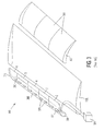
- Fig.1 is an upper, left side perspective view of a modem commercial jet aircraft 100 equipped with a plurality of slats 1-14, which are disposed along the leading edges of its wings 102L and 102R in pairs, e.g., 1/14, 2/13, 3/12, and so on, that are bilaterally symmetrical with respect to a centerline of the aircraft 100.
- the aircraft 100 also conventionally includes an elongated fuselage 104 and an empennage 106, comprising a pair of horizontal stabilizers and associated elevators 108L and 108R, and a vertical stabilizer and associated rudder 110.
- the example aircraft 100 of Fig. 1 includes a pair of bilaterally symmetrical, wing-mounted turbofan engines 112L and 112R, with one pair 7/8 of the slats 1-14 being mounted inboard of the engines 112L and 112R and six pairs 1/14, 2/13, ..., 6/9 of the slats 1-14 being mounted outboard of the engines 112L and 112R.
- all of the slats 1-14 of both wings 102L and 102R are typically extended and retracted simultaneously with each other.
- a jam in or a disconnect from a slat drive mechanism can cause a skew condition to occur in one or both ends of a slat, causing one or more of the slats to fail to move in a manner that maintains alignment along an axis with the other slats during their extension and/or retraction.
- Figs. 2A - 2D are schematic top plan views of a subset 2-6 of the slats 1-7 disposed on the left wing 102L of the aircraft 100 of Fig. 1 and outboard of its left engine 112L, showing various possible skew conditions of an intermediate one, viz., slat 4, of the outboard flaps 2-6 relative to a reference line 200 extending through all of the slats 2-6.
- Fig. 3 is a partial upper, outboard end view of the left wing 102L of the aircraft 100 of Fig. 1 , showing a prior art system 300 for detecting a skew condition in the subset 2-6 of the slats 1-6 located outboard of the left engine 112L thereof.
- the wing 112L can also include a flap assembly 302 comprising one or more flaps 304 extending rearwardly from a trailing edge of the wing 112L, and which can be extended rearwardly and downwardly in cooperation with the slats 1-7 to change the curvature of the wing 102L, and thereby increase its coefficient of lift at low speeds, as discussed above.
- the prior art slat skew detection system 300 can be similar to those described in, e.g., U.S. Pat. No. 5,680,124 to J. Bedell et al. , or U.S. Pat. No. 8,115,649 to G. Moy, et al. , the entire disclosure of each of which is incorporated herein by reference, and can comprise an elongated, flexible cable 306 that extends through a plurality of cable guides 308 disposed within each of the slats 2-6.
- the cable has one end 310 fixed within slat 6, inboard of its outboard end, and an opposite second end connected to a sensor 312, e.g., a proximity sensor, disposed inboard of the outboard end of slat 2.
- the sensor 312 is electroconductively coupled to a controller 314, which is configured to produce an alarm signal upon the detection of a skew condition in any one of slats 2-6.
- the slats 2-6 move toward and away from the wing 102L simultaneously with each other, as discussed above, and hence, the cable 306, which can comprise, e.g., a twisted wire cable that is encapsulated within a low-friction jacket, such as NYLON or TEFLON for easy sliding within the guides 308, moves in a straight line, along with the slats 2-6.
- the skew causes a pulling or tension force to be exerted in the cable 306, and hence, the sensor 312, causing it to produce a skew alarm.
- the skew detection system 300 can detect that a skew condition has arisen in one or more of the slats 2-6, it cannot detect where or within which slat(s) it has occurred.
- any skew in the slats 1 and 7, i.e., the most inboard and outboard slats 1-7 of the wing 102L, are not detected by the system 300, and 2) because the inboard end 310 of the flexible cable 306 is disposed outboard of the inboard end 316 of slat 6, and the outboard end of the cable 306 is disposed inboard of the outboard end 318 of slat 2, skews occurring at either of the ends 316 or 318 of slats 6 and 2 cannot affect the cable 306, and hence, are also not detected by the prior art system 300.
- the two slat ends 316 and 318 represent two "blind spots" in the "detection field" of the prior art system 300.
- conventional slat skew detection systems 300 typically ignore the smaller, most outboard pair of slats 1 and 14 of the aircraft 100, because, as discussed above, their loss during flight is not deemed as serious as the loss of one or more of the slats located more inboard on the wings, i.e., slats 2-7 and 8-13.
- the outboard end of the cable and sensor 312 into slat 1 so as to include the outboard end 318 of slat 2 and the inboard end of slat 1 within the detection field of the system 300, the outboard end of slat 1 and the inboard end 316 of slat 6 would still comprise blind spots in the modified system.
- slat 7 is conventionally provided with an alternate type of skew detection system 400.
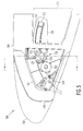
- Fig. 4 is a partial upper, outboard end view of the left wing 102L of the aircraft 100 of Fig. 1 , showing the prior art skew detection system 400, which can be implemented in a manner similar to those described in U.S. Pat. No. 5,680,124 above or in U.S. Pat. No. 8,646,346 to M. Hubberstey, et al.
- the slat 7 is selectably extended and retracted by a rotary actuator 402 that drives a drive shaft 404, e.g., a "torque tube,” upon which is mounted a pair of drive gears 404.
- Each drive gear 404 is disposed in driving engagement with a corresponding one of a pair of rack gears 406 respectively disposed on the bottom of a corresponding one of a pair of elongated slat tracks 408 respectively disposed at a corresponding end of the slat 7.
- the outer ends of the slat tracks 408 are coupled to the slat 7, and the inner ends of the slat tracks 408 are supported on rollers (not illustrated) disposed within the wing 102L for longitudinal extension and retraction away from and toward the leading edge 410 of the wing 102L, respectively.
- rollers not illustrated
- the slat tracks 408 are arched upwardly, such that movement of the slat 7 relative to the leading edge 410 of the wing 102L is forward and downward upon extension, and rearward and upward upon retraction.
- a rotary position sensor 412 e.g., a resolver
- each slat track 408 is provided with a plurality of discrete magnetic proximity targets 414 distributed along its length.
- a corresponding pair of proximity sensors 416 each of which can comprise, for example, a magnetic, Hall-effect, optical, capacitive or inductive sensor, are disposed within the wing 102L in spaced opposition to the targets 414 respectively disposed on the slat tracks 408.
- the respective output signals of the rotary position sensor 412 and the proximity sensors 416 are conveyed to a skew detector unit 418, which compares the outputs of the proximity sensors 416 with each other and that of the angular position sensor 412 to detect a skew in either or both of the ends of the slat 7 relative to the positions of the other slats 1-6.
- the skew detection system 400 provides a satisfactory mechanism for detecting skews in slat 7 (and its similarly provisioned symmetrical twin, slat 8), it is too large, heavy, complex and expensive to be implemented in slats 1-6 or the "blind spots" of the prior art system 300 discussed above, and in particular, at the inboard end of slat 6, where a skew detection system is more acutely indicated.
- FIG. 5 An example embodiment of an aircraft leading edge wing slat skew detection system 500, comprising a skew detection apparatus 501 that can be utilized at the blind spot of the inboard end of slat 6, or indeed, at the respective two ends of any one of the slats 1-14 of the aircraft 100 of Fig. 1 in place of the prior art systems 300 and/or 400 described above, is illustrated in the partial elevation view of Fig. 5 .
- Figs. 6A and 6B are rear, upper and rear, lower perspective views, respectively, of the example slat skew detection apparatus 501
- Fig. 7 is a partial cross-sectional view of the example flap skew detection apparatus 501 of Figs. 5 , 6A and 6B as seen along the lines of the section 7 - 7 taken in Fig. 5 .
- the novel skew detection system 500 is similar in some respects to the skew detection system 400 of Fig. 4 , in that it includes an elongated slat track 502 that is moveably supported in an aircraft wing 504 for longitudinal movement toward and away from a leading edge 506 of the wing 504.
- the track 502 has a forward end 508 that is coupled to a wing slat 510 for conjoint movement therewith.
- the forward end 508 of the track 502 is coupled to an end of the slat 510, for example, to the inboard end of slat 6, and it should be understood that a similar arrangement (not illustrated) can be implemented at the opposite, e.g., outboard, end of the wing slat 510, in a manner similar to the system 400 discussed above in connection with Fig. 4 .
- the forward end 508 of the track 502 is coupled to the slat 510 by a plurality of fasteners 512, such as bolts, that extend through both the track 502 and a rearwardly extending tongue on the wing slat 510, although other coupling mechanisms can be used instead or in place of the bolts and tongue.
- the track 502 can include a rear end 512 that extends rearwardly into the wing 504 and can, for example be enclosed within a housing 514 to isolate it from the contents of, for example, a fuel tank 516 disposed within the wing 504.
- the slat track 502 is upwardly arched such that, as discussed above in connection with the system 400 of Fig. 4 , the slat 510 moves forward and downward relative to the leading edge 506 of the wing 504 upon extension, and rearward and upward relative to the leading edge 506 upon retraction.
- the slat track 502 can be supported within the wing 504 by a pair of support ribs 518 located within the wing 504 and respectively disposed and on opposite sides of the track 502.
- the track 502 can be moveably supported within the wing 504 between a plurality of bearings 520, e.g., roller bearings or ball bearings. As illustrated in Figs. 6A and 7 , these can comprise upper and lower sets of the bearings 520.
- An actuator 522 is configured to selectably drive the track 502 between retracted and extended positions relative to the leading edge 506 of the wing 504.
- the actuator 522 comprises a drive gear 524 that is rotatably mounted in the wing 504 and disposed in meshing engagement with a rack gear 526 disposed on the track 502, and a rotary actuator 528 drivingly coupled to and configured to selectably rotate the drive gear 524 in opposite directions to move the slat 510 longitudinally in and out of the wing 504.
- the cross-section of the track 502 can comprise, for example, an inverted U shape, and the rack gear 526 can be disposed internally of the U at its bottom.
- the slat skew detection apparatus 501 of the system 500 comprises a pinion gear 530 that is rotatably mounted in the wing 504 and disposed in rolling engagement with the rack gear 526 of the track 502, and a rotary sensor 532 that is coupled to the pinion gear 530 and configured to sense the longitudinal position of the slat 510 relative to the leading edge 506 of the wing 504 as a function of the rotational position of the pinion gear 530.
- a pinion gear 530 that is rotatably mounted in the wing 504 and disposed in rolling engagement with the rack gear 526 of the track 502
- a rotary sensor 532 that is coupled to the pinion gear 530 and configured to sense the longitudinal position of the slat 510 relative to the leading edge 506 of the wing 504 as a function of the rotational position of the pinion gear 530.
- the sensor 532 can comprise a pair of sensors 532 that are coupled to the pinion gear 530 in parallel for purposes of redundancy, i.e., their outputs can be averaged in normal use, and if one sensor 530 fails in use, the output of the other can be used in place of the average.
- the sensor(s) 532 can be rotatably coupled to the pinion gear 530 through a gear train contained in a gear box 534, which, through gear reduction or gear multiplication, can enable a small number of turns of the pinion gear 530 to effect a large number of turns of the sensor 532, or vice versa. In this way, only a small rotation of the pinion gear 530, e.g., less than a single revolution, might be experienced between a full extension and a full retraction of the slat 510, to produce a relatively large number of revolutions of the input of the rotary sensor 532.
- the pinion gear 532 can, for weight and size reduction purposes, comprise a gear with a circumferential segment that has no teeth, i.e., a sector gear.
- the pinion gear 530 is fixed, e.g., splined, on a shaft 536 that is rotatably mounted in the track support ribs 518 of the wing 504 by, e.g., a plurality of bearings 538, e.g., roller bearings or ball bearings.
- the shaft 536 can contain a central lumen 540 with suitably disposed openings to the bearings 520 of the track 502, through which a lubricant injected into the lumen can reach and lubricate the track bearings 520.
- An input end of the gear train of the gear box 534 can be coupled to an output end the shaft 534 by a short "quill shaft" 542.
- the skew detection apparatus 501 of the system 500 coaxially with the support bearings 520 of the slat track 502 and inboard of the two support ribs 518, a skew detection apparatus results that is substantially more compact and lighter in weight than that of the skew detection system 400 described above, and further, by utilizing standard gear and sensor components, one that is also less costly to implement.
- the sensor 530 can comprise a variety of conventional, off-the-shelf rotary sensors, e.g., encoders, potentiometers, or resolvers of almost any practical resolution and precision desired.
- the senor 530 can comprise a rotary or shaft encoder of a known type that utilizes electroconductive principles, optical principles, or magnetic principles, e.g., an "on-axis" magnetic encoder or an "off-axis” magnetic encoder.
- the slat track 502 and hence, the end of the wing slat 510 to which it is attached, is driven longitudinally between retracted and extended positions relative to the leading edge 506 of the wing 504 by the slat actuator 522.
- the pinion gear 530 rotates through an angular displacement that is proportional to the longitudinal displacement of the track 502, and hence, the longitudinal position of the end of the slat 510 coupled to its outer end 508.
- the longitudinal position of the slat 510 can be sensed by sensing the rotational position of the pinion gear 530 with the rotary sensor 532.
- Detection of a skewed condition of the slat 510 can be effected by using the sensed position of the end of the slat 510, e.g., by comparing the sensed position of the end of the slat 510 with the position of the opposite end of the slat 510, and/or to the position of an end of another slat, for example, with that of the bilaterally symmetrical twin of the slat 510 disposed on the other wing of the aircraft.
Landscapes
- Engineering & Computer Science (AREA)
- General Engineering & Computer Science (AREA)
- Aviation & Aerospace Engineering (AREA)
- Mechanical Engineering (AREA)
- Measurement Of Length, Angles, Or The Like Using Electric Or Magnetic Means (AREA)
- Retarders (AREA)
- Position Fixing By Use Of Radio Waves (AREA)
Applications Claiming Priority (1)
| Application Number | Priority Date | Filing Date | Title |
|---|---|---|---|
| US14/683,036 US9815570B2 (en) | 2015-04-09 | 2015-04-09 | Aircraft wing slat skew detection systems and methods |
Publications (2)
| Publication Number | Publication Date |
|---|---|
| EP3078596A1 true EP3078596A1 (fr) | 2016-10-12 |
| EP3078596B1 EP3078596B1 (fr) | 2018-08-29 |
Family
ID=55442647
Family Applications (1)
| Application Number | Title | Priority Date | Filing Date |
|---|---|---|---|
| EP16155974.5A Active EP3078596B1 (fr) | 2015-04-09 | 2016-02-16 | Systèmes et procédés de détection de désalignement de bec de bord d'attaque d'aile d'avion |
Country Status (4)
| Country | Link |
|---|---|
| US (1) | US9815570B2 (fr) |
| EP (1) | EP3078596B1 (fr) |
| CA (1) | CA2918142C (fr) |
| ES (1) | ES2699701T3 (fr) |
Cited By (4)
| Publication number | Priority date | Publication date | Assignee | Title |
|---|---|---|---|---|
| GB2585652A (en) * | 2019-07-09 | 2021-01-20 | Moog Wolverhampton Ltd | Skew and loss detection system |
| EP3812265A1 (fr) * | 2019-10-25 | 2021-04-28 | Hamilton Sundstrand Corporation | Surveillance du couple de transmission pour l'évaluation de l'état à long terme |
| EP3995399A1 (fr) * | 2020-11-10 | 2022-05-11 | The Boeing Company | Systèmes d'actionnement de surface de commande de vol comprenant des systèmes de détection d'obliquité, et procédés associés |
| US11583438B1 (en) | 2007-08-21 | 2023-02-21 | Zeltiq Aesthetics, Inc. | Monitoring the cooling of subcutaneous lipid-rich cells, such as the cooling of adipose tissue |
Families Citing this family (16)
| Publication number | Priority date | Publication date | Assignee | Title |
|---|---|---|---|---|
| WO2016010918A1 (fr) | 2014-07-13 | 2016-01-21 | Dana Automotive Systems Group, Llc | Procédé et système de verrouillage d'un actionneur |
| US10323699B2 (en) * | 2015-07-02 | 2019-06-18 | Dana Automotive Systems Group, Llc | Electromagnetic connect/disconnect system for a vehicle |
| US10654587B2 (en) * | 2015-09-10 | 2020-05-19 | The Boeing Company | Aircraft flight control surface actuation monitoring system and method |
| US10053237B2 (en) * | 2016-05-20 | 2018-08-21 | The Boeing Company | Track roller failure detection systems and methods |
| EP3339165B1 (fr) | 2016-12-22 | 2020-09-09 | Goodrich Actuation Systems Limited | Détection de désaccouplement d'actionneur des becs de voilure |
| US10690520B2 (en) | 2017-02-27 | 2020-06-23 | The Boeing Company | Apparatus, system, and method for determining a position of a part |
| GB201809573D0 (en) * | 2018-06-11 | 2018-07-25 | Moog Wolverhampton Ltd | Control surface element skew and/or loss detection system |
| CN108945517A (zh) * | 2018-07-27 | 2018-12-07 | 中国商用飞机有限责任公司 | 飞机缝翼倾斜探测装置及其定位方法 |
| CN108945516A (zh) * | 2018-07-27 | 2018-12-07 | 中国商用飞机有限责任公司 | 飞机缝翼倾斜探测装置及其定位方法 |
| GB2582149A (en) * | 2019-03-12 | 2020-09-16 | Airbus Operations Ltd | Slat for an aircraft wing |
| US11312473B2 (en) | 2019-05-30 | 2022-04-26 | The Boeing Company | Aircraft slat aero-restoration seal door and method therefor |
| EP4086166B1 (fr) * | 2021-05-03 | 2025-08-06 | Airbus Operations GmbH | Aile d'aéronef |
| EP4112450A1 (fr) * | 2021-06-30 | 2023-01-04 | Airbus Operations GmbH | Aile d'aéronef |
| US11970269B2 (en) | 2022-05-13 | 2024-04-30 | The Boeing Company | Assemblies for air vehicle control surfaces including a bullnose |
| US11820490B1 (en) * | 2022-05-23 | 2023-11-21 | The Boeing Company | Methods, apparatus, and articles of manufacture for actuating control surfaces of an aircraft |
| CN116045883A (zh) * | 2022-09-08 | 2023-05-02 | 辽宁华天航空科技股份有限公司 | 一种飞机机翼的生产质量检测方法及系统 |
Citations (5)
| Publication number | Priority date | Publication date | Assignee | Title |
|---|---|---|---|---|
| US5680124A (en) | 1995-05-15 | 1997-10-21 | The Boeing Company | Skew and loss detection system for adjacent high lift devices |
| EP1088753A2 (fr) * | 1999-09-28 | 2001-04-04 | Lucas Industries Limited | Appareil pour la détection d'un désalignement |
| US8115649B2 (en) | 2009-04-30 | 2012-02-14 | The Boeing Company | Slat skew detection system |
| US8646346B2 (en) | 2009-11-16 | 2014-02-11 | Goodrich Actuation Systems Limited | Skew detection |
| EP2881714A1 (fr) * | 2013-12-06 | 2015-06-10 | Rosemount Aerospace Inc. | Systèmes de détection d'obliquité de surface de commande |
Family Cites Families (13)
| Publication number | Priority date | Publication date | Assignee | Title |
|---|---|---|---|---|
| US2969933A (en) * | 1951-10-02 | 1961-01-31 | Vogt Richard | Linking airplanes and wings of airplanes |
| US4470569A (en) * | 1981-12-28 | 1984-09-11 | Mcdonnell Douglas Corporation | Locking, redundant slat drive mechanism |
| US5628477A (en) * | 1995-02-13 | 1997-05-13 | The Boeing Company | Auxiliary airfoil lost motion detector and actuator |
| US5686907A (en) * | 1995-05-15 | 1997-11-11 | The Boeing Company | Skew and loss detection system for individual high lift devices |
| US6299108B1 (en) | 1997-12-12 | 2001-10-09 | Jeffrey V. Lindstrom | Method and apparatus for detecting skew and asymmetry of an airplane flap |
| US6483436B1 (en) * | 2001-05-21 | 2002-11-19 | Hamilton Sundstrand Corporation | Method and apparatus for sensing skews and disconnects of adjacent movable components |
| DE10313728B4 (de) * | 2003-03-27 | 2011-07-21 | Airbus Operations GmbH, 21129 | Klappensystem am Tragflügel eines Starrflügel-Flugzeuges |
| DE102007018330A1 (de) | 2007-04-18 | 2008-10-23 | Liebherr-Aerospace Lindenberg Gmbh | Vorrichtung zur Überwachung des Gleichlaufs von Klappen eines Flugzeugflügels |
| US7945425B2 (en) | 2008-10-17 | 2011-05-17 | The Boeing Company | In-flight detection of wing flap free wheeling skew |
| DE102009020840A1 (de) * | 2009-05-12 | 2010-11-25 | Liebherr-Aerospace Lindenberg Gmbh | Flugzeughochauftriebssystem sowie Verfahren zur Ermittlung eines Betriebszustandes eines Flugzeughochauftriebssystems |
| GB201004026D0 (en) * | 2010-03-10 | 2010-04-28 | Airbus Operations Ltd | Slat monitoring system |
| GB201008773D0 (en) * | 2010-05-26 | 2010-07-14 | Airbus Uk Ltd | Aircraft slat assembly |
| GB201120234D0 (en) | 2011-11-23 | 2012-01-04 | Airbus Operations Ltd | Deployment system |
-
2015
- 2015-04-09 US US14/683,036 patent/US9815570B2/en active Active
-
2016
- 2016-01-19 CA CA2918142A patent/CA2918142C/fr active Active
- 2016-02-16 EP EP16155974.5A patent/EP3078596B1/fr active Active
- 2016-02-16 ES ES16155974T patent/ES2699701T3/es active Active
Patent Citations (5)
| Publication number | Priority date | Publication date | Assignee | Title |
|---|---|---|---|---|
| US5680124A (en) | 1995-05-15 | 1997-10-21 | The Boeing Company | Skew and loss detection system for adjacent high lift devices |
| EP1088753A2 (fr) * | 1999-09-28 | 2001-04-04 | Lucas Industries Limited | Appareil pour la détection d'un désalignement |
| US8115649B2 (en) | 2009-04-30 | 2012-02-14 | The Boeing Company | Slat skew detection system |
| US8646346B2 (en) | 2009-11-16 | 2014-02-11 | Goodrich Actuation Systems Limited | Skew detection |
| EP2881714A1 (fr) * | 2013-12-06 | 2015-06-10 | Rosemount Aerospace Inc. | Systèmes de détection d'obliquité de surface de commande |
Cited By (7)
| Publication number | Priority date | Publication date | Assignee | Title |
|---|---|---|---|---|
| US11583438B1 (en) | 2007-08-21 | 2023-02-21 | Zeltiq Aesthetics, Inc. | Monitoring the cooling of subcutaneous lipid-rich cells, such as the cooling of adipose tissue |
| GB2585652A (en) * | 2019-07-09 | 2021-01-20 | Moog Wolverhampton Ltd | Skew and loss detection system |
| GB2585652B (en) * | 2019-07-09 | 2021-07-14 | Moog Wolverhampton Ltd | Skew and loss detection system |
| EP3812265A1 (fr) * | 2019-10-25 | 2021-04-28 | Hamilton Sundstrand Corporation | Surveillance du couple de transmission pour l'évaluation de l'état à long terme |
| US11485476B2 (en) * | 2019-10-25 | 2022-11-01 | Hamilton Sundstrand Corporation | Driveline torque monitoring for long-term health assessment |
| EP3995399A1 (fr) * | 2020-11-10 | 2022-05-11 | The Boeing Company | Systèmes d'actionnement de surface de commande de vol comprenant des systèmes de détection d'obliquité, et procédés associés |
| US11884380B2 (en) | 2020-11-10 | 2024-01-30 | The Boeing Company | Flight control surface actuation systems including skew detection systems, and associated methods |
Also Published As
| Publication number | Publication date |
|---|---|
| CA2918142C (fr) | 2021-06-22 |
| ES2699701T3 (es) | 2019-02-12 |
| CA2918142A1 (fr) | 2016-10-09 |
| EP3078596B1 (fr) | 2018-08-29 |
| US20160297541A1 (en) | 2016-10-13 |
| US9815570B2 (en) | 2017-11-14 |
Similar Documents
| Publication | Publication Date | Title |
|---|---|---|
| US9815570B2 (en) | Aircraft wing slat skew detection systems and methods | |
| EP3643619A1 (fr) | Système de détection de désalignement d'aéronef et son procédé d'utilisation | |
| CN109153441B (zh) | 利用从动螺杆驱动双开缝襟翼的装置和方法 | |
| US9193479B2 (en) | Monitoring of high-lift systems for aircraft | |
| US10654587B2 (en) | Aircraft flight control surface actuation monitoring system and method | |
| US10053237B2 (en) | Track roller failure detection systems and methods | |
| US9963220B2 (en) | Flap deploying device and aircraft | |
| US8544793B1 (en) | Adjustable angle inlet for turbojet engines | |
| US20100100355A1 (en) | In-flight detection of wing flap free wheeling skew | |
| US8152110B2 (en) | Sensor system for monitoring the synchronism of control surfaces of an aircraft | |
| US20180162516A1 (en) | Aircraft wing system | |
| US20180162517A1 (en) | Aircraft wing system | |
| US20040084570A1 (en) | Lift adjusting device for aircraft | |
| EP3995399B1 (fr) | Systèmes d'actionnement de surface de commande de vol comprenant des systèmes de détection d'obliquité, et procédés associés | |
| EP4421495A1 (fr) | Système de capteur de véhicule | |
| US11815368B2 (en) | Dual-mount for spring-loaded gear-driven resolvers | |
| US12545431B2 (en) | Health monitoring system | |
| JP2004050855A (ja) | 舵面異常検出装置 | |
| US12522346B2 (en) | Protection system | |
| Fink et al. | The effects of configuration changes on the aerodynamic characteristics of a full-scale mockup of a light twin engine airplane | |
| BR102024015751A2 (pt) | Método para realizar monitoramento de integridade, sistemas de monitoramento de integridade e de hélice de arfagem variável, e, aeronave | |
| JP2004066934A (ja) | 舵面異常検出装置 |
Legal Events
| Date | Code | Title | Description |
|---|---|---|---|
| PUAI | Public reference made under article 153(3) epc to a published international application that has entered the european phase |
Free format text: ORIGINAL CODE: 0009012 |
|
| AK | Designated contracting states |
Kind code of ref document: A1 Designated state(s): AL AT BE BG CH CY CZ DE DK EE ES FI FR GB GR HR HU IE IS IT LI LT LU LV MC MK MT NL NO PL PT RO RS SE SI SK SM TR |
|
| AX | Request for extension of the european patent |
Extension state: BA ME |
|
| STAA | Information on the status of an ep patent application or granted ep patent |
Free format text: STATUS: REQUEST FOR EXAMINATION WAS MADE |
|
| 17P | Request for examination filed |
Effective date: 20170330 |
|
| RBV | Designated contracting states (corrected) |
Designated state(s): AL AT BE BG CH CY CZ DE DK EE ES FI FR GB GR HR HU IE IS IT LI LT LU LV MC MK MT NL NO PL PT RO RS SE SI SK SM TR |
|
| GRAP | Despatch of communication of intention to grant a patent |
Free format text: ORIGINAL CODE: EPIDOSNIGR1 |
|
| STAA | Information on the status of an ep patent application or granted ep patent |
Free format text: STATUS: GRANT OF PATENT IS INTENDED |
|
| INTG | Intention to grant announced |
Effective date: 20180305 |
|
| GRAS | Grant fee paid |
Free format text: ORIGINAL CODE: EPIDOSNIGR3 |
|
| GRAA | (expected) grant |
Free format text: ORIGINAL CODE: 0009210 |
|
| STAA | Information on the status of an ep patent application or granted ep patent |
Free format text: STATUS: THE PATENT HAS BEEN GRANTED |
|
| AK | Designated contracting states |
Kind code of ref document: B1 Designated state(s): AL AT BE BG CH CY CZ DE DK EE ES FI FR GB GR HR HU IE IS IT LI LT LU LV MC MK MT NL NO PL PT RO RS SE SI SK SM TR |
|
| REG | Reference to a national code |
Ref country code: GB Ref legal event code: FG4D |
|
| REG | Reference to a national code |
Ref country code: CH Ref legal event code: EP |
|
| REG | Reference to a national code |
Ref country code: AT Ref legal event code: REF Ref document number: 1034831 Country of ref document: AT Kind code of ref document: T Effective date: 20180915 |
|
| REG | Reference to a national code |
Ref country code: IE Ref legal event code: FG4D |
|
| REG | Reference to a national code |
Ref country code: DE Ref legal event code: R096 Ref document number: 602016005050 Country of ref document: DE |
|
| REG | Reference to a national code |
Ref country code: NL Ref legal event code: MP Effective date: 20180829 |
|
| REG | Reference to a national code |
Ref country code: LT Ref legal event code: MG4D |
|
| PG25 | Lapsed in a contracting state [announced via postgrant information from national office to epo] |
Ref country code: RS Free format text: LAPSE BECAUSE OF FAILURE TO SUBMIT A TRANSLATION OF THE DESCRIPTION OR TO PAY THE FEE WITHIN THE PRESCRIBED TIME-LIMIT Effective date: 20180829 Ref country code: FI Free format text: LAPSE BECAUSE OF FAILURE TO SUBMIT A TRANSLATION OF THE DESCRIPTION OR TO PAY THE FEE WITHIN THE PRESCRIBED TIME-LIMIT Effective date: 20180829 Ref country code: SE Free format text: LAPSE BECAUSE OF FAILURE TO SUBMIT A TRANSLATION OF THE DESCRIPTION OR TO PAY THE FEE WITHIN THE PRESCRIBED TIME-LIMIT Effective date: 20180829 Ref country code: BG Free format text: LAPSE BECAUSE OF FAILURE TO SUBMIT A TRANSLATION OF THE DESCRIPTION OR TO PAY THE FEE WITHIN THE PRESCRIBED TIME-LIMIT Effective date: 20181129 Ref country code: NO Free format text: LAPSE BECAUSE OF FAILURE TO SUBMIT A TRANSLATION OF THE DESCRIPTION OR TO PAY THE FEE WITHIN THE PRESCRIBED TIME-LIMIT Effective date: 20181129 Ref country code: IS Free format text: LAPSE BECAUSE OF FAILURE TO SUBMIT A TRANSLATION OF THE DESCRIPTION OR TO PAY THE FEE WITHIN THE PRESCRIBED TIME-LIMIT Effective date: 20181229 Ref country code: NL Free format text: LAPSE BECAUSE OF FAILURE TO SUBMIT A TRANSLATION OF THE DESCRIPTION OR TO PAY THE FEE WITHIN THE PRESCRIBED TIME-LIMIT Effective date: 20180829 Ref country code: LT Free format text: LAPSE BECAUSE OF FAILURE TO SUBMIT A TRANSLATION OF THE DESCRIPTION OR TO PAY THE FEE WITHIN THE PRESCRIBED TIME-LIMIT Effective date: 20180829 Ref country code: GR Free format text: LAPSE BECAUSE OF FAILURE TO SUBMIT A TRANSLATION OF THE DESCRIPTION OR TO PAY THE FEE WITHIN THE PRESCRIBED TIME-LIMIT Effective date: 20181130 |
|
| REG | Reference to a national code |
Ref country code: ES Ref legal event code: FG2A Ref document number: 2699701 Country of ref document: ES Kind code of ref document: T3 Effective date: 20190212 |
|
| REG | Reference to a national code |
Ref country code: AT Ref legal event code: MK05 Ref document number: 1034831 Country of ref document: AT Kind code of ref document: T Effective date: 20180829 |
|
| PG25 | Lapsed in a contracting state [announced via postgrant information from national office to epo] |
Ref country code: HR Free format text: LAPSE BECAUSE OF FAILURE TO SUBMIT A TRANSLATION OF THE DESCRIPTION OR TO PAY THE FEE WITHIN THE PRESCRIBED TIME-LIMIT Effective date: 20180829 Ref country code: AL Free format text: LAPSE BECAUSE OF FAILURE TO SUBMIT A TRANSLATION OF THE DESCRIPTION OR TO PAY THE FEE WITHIN THE PRESCRIBED TIME-LIMIT Effective date: 20180829 Ref country code: LV Free format text: LAPSE BECAUSE OF FAILURE TO SUBMIT A TRANSLATION OF THE DESCRIPTION OR TO PAY THE FEE WITHIN THE PRESCRIBED TIME-LIMIT Effective date: 20180829 |
|
| PG25 | Lapsed in a contracting state [announced via postgrant information from national office to epo] |
Ref country code: PL Free format text: LAPSE BECAUSE OF FAILURE TO SUBMIT A TRANSLATION OF THE DESCRIPTION OR TO PAY THE FEE WITHIN THE PRESCRIBED TIME-LIMIT Effective date: 20180829 Ref country code: CZ Free format text: LAPSE BECAUSE OF FAILURE TO SUBMIT A TRANSLATION OF THE DESCRIPTION OR TO PAY THE FEE WITHIN THE PRESCRIBED TIME-LIMIT Effective date: 20180829 Ref country code: EE Free format text: LAPSE BECAUSE OF FAILURE TO SUBMIT A TRANSLATION OF THE DESCRIPTION OR TO PAY THE FEE WITHIN THE PRESCRIBED TIME-LIMIT Effective date: 20180829 Ref country code: RO Free format text: LAPSE BECAUSE OF FAILURE TO SUBMIT A TRANSLATION OF THE DESCRIPTION OR TO PAY THE FEE WITHIN THE PRESCRIBED TIME-LIMIT Effective date: 20180829 Ref country code: AT Free format text: LAPSE BECAUSE OF FAILURE TO SUBMIT A TRANSLATION OF THE DESCRIPTION OR TO PAY THE FEE WITHIN THE PRESCRIBED TIME-LIMIT Effective date: 20180829 |
|
| PG25 | Lapsed in a contracting state [announced via postgrant information from national office to epo] |
Ref country code: DK Free format text: LAPSE BECAUSE OF FAILURE TO SUBMIT A TRANSLATION OF THE DESCRIPTION OR TO PAY THE FEE WITHIN THE PRESCRIBED TIME-LIMIT Effective date: 20180829 Ref country code: SM Free format text: LAPSE BECAUSE OF FAILURE TO SUBMIT A TRANSLATION OF THE DESCRIPTION OR TO PAY THE FEE WITHIN THE PRESCRIBED TIME-LIMIT Effective date: 20180829 Ref country code: SK Free format text: LAPSE BECAUSE OF FAILURE TO SUBMIT A TRANSLATION OF THE DESCRIPTION OR TO PAY THE FEE WITHIN THE PRESCRIBED TIME-LIMIT Effective date: 20180829 |
|
| REG | Reference to a national code |
Ref country code: DE Ref legal event code: R097 Ref document number: 602016005050 Country of ref document: DE |
|
| PLBE | No opposition filed within time limit |
Free format text: ORIGINAL CODE: 0009261 |
|
| STAA | Information on the status of an ep patent application or granted ep patent |
Free format text: STATUS: NO OPPOSITION FILED WITHIN TIME LIMIT |
|
| 26N | No opposition filed |
Effective date: 20190531 |
|
| PG25 | Lapsed in a contracting state [announced via postgrant information from national office to epo] |
Ref country code: SI Free format text: LAPSE BECAUSE OF FAILURE TO SUBMIT A TRANSLATION OF THE DESCRIPTION OR TO PAY THE FEE WITHIN THE PRESCRIBED TIME-LIMIT Effective date: 20180829 |
|
| REG | Reference to a national code |
Ref country code: CH Ref legal event code: PL |
|
| PG25 | Lapsed in a contracting state [announced via postgrant information from national office to epo] |
Ref country code: LU Free format text: LAPSE BECAUSE OF NON-PAYMENT OF DUE FEES Effective date: 20190216 Ref country code: MC Free format text: LAPSE BECAUSE OF FAILURE TO SUBMIT A TRANSLATION OF THE DESCRIPTION OR TO PAY THE FEE WITHIN THE PRESCRIBED TIME-LIMIT Effective date: 20180829 |
|
| REG | Reference to a national code |
Ref country code: BE Ref legal event code: MM Effective date: 20190228 |
|
| REG | Reference to a national code |
Ref country code: IE Ref legal event code: MM4A |
|
| PG25 | Lapsed in a contracting state [announced via postgrant information from national office to epo] |
Ref country code: CH Free format text: LAPSE BECAUSE OF NON-PAYMENT OF DUE FEES Effective date: 20190228 Ref country code: LI Free format text: LAPSE BECAUSE OF NON-PAYMENT OF DUE FEES Effective date: 20190228 |
|
| PG25 | Lapsed in a contracting state [announced via postgrant information from national office to epo] |
Ref country code: IE Free format text: LAPSE BECAUSE OF NON-PAYMENT OF DUE FEES Effective date: 20190216 |
|
| PG25 | Lapsed in a contracting state [announced via postgrant information from national office to epo] |
Ref country code: BE Free format text: LAPSE BECAUSE OF NON-PAYMENT OF DUE FEES Effective date: 20190228 |
|
| PG25 | Lapsed in a contracting state [announced via postgrant information from national office to epo] |
Ref country code: TR Free format text: LAPSE BECAUSE OF FAILURE TO SUBMIT A TRANSLATION OF THE DESCRIPTION OR TO PAY THE FEE WITHIN THE PRESCRIBED TIME-LIMIT Effective date: 20180829 |
|
| PG25 | Lapsed in a contracting state [announced via postgrant information from national office to epo] |
Ref country code: PT Free format text: LAPSE BECAUSE OF FAILURE TO SUBMIT A TRANSLATION OF THE DESCRIPTION OR TO PAY THE FEE WITHIN THE PRESCRIBED TIME-LIMIT Effective date: 20181229 Ref country code: MT Free format text: LAPSE BECAUSE OF NON-PAYMENT OF DUE FEES Effective date: 20190216 |
|
| PG25 | Lapsed in a contracting state [announced via postgrant information from national office to epo] |
Ref country code: CY Free format text: LAPSE BECAUSE OF FAILURE TO SUBMIT A TRANSLATION OF THE DESCRIPTION OR TO PAY THE FEE WITHIN THE PRESCRIBED TIME-LIMIT Effective date: 20180829 |
|
| PG25 | Lapsed in a contracting state [announced via postgrant information from national office to epo] |
Ref country code: HU Free format text: LAPSE BECAUSE OF FAILURE TO SUBMIT A TRANSLATION OF THE DESCRIPTION OR TO PAY THE FEE WITHIN THE PRESCRIBED TIME-LIMIT; INVALID AB INITIO Effective date: 20160216 |
|
| PG25 | Lapsed in a contracting state [announced via postgrant information from national office to epo] |
Ref country code: MK Free format text: LAPSE BECAUSE OF FAILURE TO SUBMIT A TRANSLATION OF THE DESCRIPTION OR TO PAY THE FEE WITHIN THE PRESCRIBED TIME-LIMIT Effective date: 20180829 |
|
| P01 | Opt-out of the competence of the unified patent court (upc) registered |
Effective date: 20230516 |
|
| PGFP | Annual fee paid to national office [announced via postgrant information from national office to epo] |
Ref country code: GB Payment date: 20260227 Year of fee payment: 11 |
|
| PGFP | Annual fee paid to national office [announced via postgrant information from national office to epo] |
Ref country code: ES Payment date: 20260302 Year of fee payment: 11 |
|
| PGFP | Annual fee paid to national office [announced via postgrant information from national office to epo] |
Ref country code: DE Payment date: 20260227 Year of fee payment: 11 |
|
| PGFP | Annual fee paid to national office [announced via postgrant information from national office to epo] |
Ref country code: IT Payment date: 20260219 Year of fee payment: 11 |
|
| PGFP | Annual fee paid to national office [announced via postgrant information from national office to epo] |
Ref country code: FR Payment date: 20260225 Year of fee payment: 11 |