EP3078614A1 - Ladewerk für ein abfallsammelfahrzeug - Google Patents
Ladewerk für ein abfallsammelfahrzeug Download PDFInfo
- Publication number
- EP3078614A1 EP3078614A1 EP15200760.5A EP15200760A EP3078614A1 EP 3078614 A1 EP3078614 A1 EP 3078614A1 EP 15200760 A EP15200760 A EP 15200760A EP 3078614 A1 EP3078614 A1 EP 3078614A1
- Authority
- EP
- European Patent Office
- Prior art keywords
- plate cylinder
- support
- loading
- cross member
- side surfaces
- Prior art date
- Legal status (The legal status is an assumption and is not a legal conclusion. Google has not performed a legal analysis and makes no representation as to the accuracy of the status listed.)
- Granted
Links
Images


Classifications
-
- B—PERFORMING OPERATIONS; TRANSPORTING
- B65—CONVEYING; PACKING; STORING; HANDLING THIN OR FILAMENTARY MATERIAL
- B65F—GATHERING OR REMOVAL OF DOMESTIC OR LIKE REFUSE
- B65F3/00—Vehicles particularly adapted for collecting refuse
- B65F3/14—Vehicles particularly adapted for collecting refuse with devices for charging, distributing or compressing refuse in the interior of the tank of a refuse vehicle
- B65F3/20—Vehicles particularly adapted for collecting refuse with devices for charging, distributing or compressing refuse in the interior of the tank of a refuse vehicle with charging pistons, plates, or the like
-
- B—PERFORMING OPERATIONS; TRANSPORTING
- B65—CONVEYING; PACKING; STORING; HANDLING THIN OR FILAMENTARY MATERIAL
- B65F—GATHERING OR REMOVAL OF DOMESTIC OR LIKE REFUSE
- B65F3/00—Vehicles particularly adapted for collecting refuse
- B65F3/14—Vehicles particularly adapted for collecting refuse with devices for charging, distributing or compressing refuse in the interior of the tank of a refuse vehicle
- B65F3/20—Vehicles particularly adapted for collecting refuse with devices for charging, distributing or compressing refuse in the interior of the tank of a refuse vehicle with charging pistons, plates, or the like
- B65F3/207—Vehicles particularly adapted for collecting refuse with devices for charging, distributing or compressing refuse in the interior of the tank of a refuse vehicle with charging pistons, plates, or the like guided by tracks, channels, slots or the like provided on the vehicle
Definitions
- the present invention relates to a loading plant for a refuse collection vehicle.
- the loading station is used for picking up, reducing and introducing solids into the refuse collection vehicle.
- it is typically arranged at the rear of a waste collection vehicle and has a pouring opening, a loading pan and a discharge opening.
- the discharge opening is typically connected to a container located on the refuse collection vehicle.
- the loading mechanism comprises a pressing device comprising a carrier plate and a pressing plate.
- the pressing plate is pivotally mounted on the support plate and can move together with the support plate.
- the objects to be brought into the refuse collection vehicle are conveyed into the loading station or into the loading trough and then comminuted with the aid of the pressing plant and passed on to the container of the refuse collection vehicle.
- the support plate, at the end of the loading tub facing the press plate is hinged, moved in the direction of the loading pan, and thereafter by a pivoting movement of the press plate, the objects crushed and / or pressed.
- the pressed articles are conveyed into the container of the refuse collection vehicle.
- the frame of the loading unit must be designed to be particularly strong and rigid. However, this requires a high weight and thus leads to high operating costs of a waste collection vehicle with such Ladewerk.
- the aim of the present invention is therefore to develop a loading unit for a refuse collection vehicle to the effect that it has less weight with the same stability.
- the loading unit according to the invention for a refuse collection vehicle comprises a frame structure of the loading station, a support plate which is connected via a carrier plate cylinder to the frame structure, and a pressure plate which is connected via a press plate cylinder with the support plate cylinder. Furthermore, the loading unit is characterized in that the carrier plate cylinder is integrated into the load-bearing structure of the loading unit.
- the carrier plate cylinder By incorporating the carrier plate cylinder into the load-bearing structure of the loading station, the carrier plate cylinder has a supporting effect. This contributes to the fact that the loading unit per se can be constructed with less robust components without impairing the necessary properties in terms of stability and connection rigidity.
- the frame structure of Ladetechnik s two opposing side surfaces and connecting these side surfaces cross member.
- the cross member is enclosed in its circumferential direction by a holding element which projects approximately perpendicular to the longitudinal direction of the cross member Attachment plates, between which a to the longitudinal direction of the cross member approximately parallel aligned mounting rod is mounted.
- the retaining element encloses the cross member only partially.
- the support plate cylinder is directly connected to the mounting rod, whereby this is integrated into the supporting structure of the loading plant.
- the mounting rod is enclosed in a portion of an out of the support plate cylinder end of a piston.
- the holding element surrounds the cross member such that a force perpendicular to the longitudinal direction of the cross member is discharged via the holding element into the structure of the cross member.
- the cross member has a basic shape, which does not allow a rotation about the longitudinal axis of the cross member when enclosing this basic shape.
- the carrier plate cylinder is arranged between two side surfaces of the loading unit.
- At least one of two side surfaces of the loading unit has a support on the side facing the other side surface.
- the support is a separate element to the side surface, for example.
- a bar which adjoins the side surface with its flat side.
- the support may also be considered as a rib, which is arranged on a flat surface of the side surface.
- the support is attached to the side surface.
- the support may also be a protruding from the side surface elevation, which is formed integrally with the side surface.
- this support is advantageous in terms of the embodiments of the side surfaces, since the support at a defined load bending stresses can absorb the side surfaces.
- the support by the support, the side surface per se be made in a smaller thickness. This ultimately leads to a lower weight of the charging plant and to a lower energy consumption of a refuse collection vehicle with the charging plant.
- the support serves to dissipate a force during extension of the press plate cylinder.
- the support is adapted to be in sliding contact with a sliding block.
- the sliding block is in a rigid connection with the movable part of the support plate cylinder.
- the non-movable part of the press plate cylinder is in a rigid connection with the sliding block.
- the support plate cylinder is first extended and the waste introduced into the loading pan is broken by the pressure plate. This is done by the movement of the support plate, at the end of the loading tub facing the press plate is articulated. By the movement of the carrier plate or the pressing plate in the direction of the charging tray, the waste accumulated therein is broken. To achieve this, only the support plate cylinder is moved from its retracted position to an extended position. Thereafter, the platen cylinder extends and compacts the waste by means of a pivoting movement, so that the waste accumulated in the loading pan is pressed against a loading pan wall near a discharge opening. This results in considerable forces that the press plate cylinder has to apply and must also initiate into the frame structure of the loader. In a last step, the support plate cylinder is moved back to its retracted position and the compressed waste is conveyed through a discharge opening.
- the press plate cylinder is connected to the support plate cylinder and the support plate cylinder with its movable part via a sliding block in a sliding connection with the support, the forces acting during the pressing process forces can be effectively derived via the support and need not be derived via the support plate cylinder or a holder of the support plate cylinder. In other words, therefore, the force of the pressure plate cylinder acting during the pressing process can be conducted via a sliding block to the support in the side surfaces.
- the connection of the carrier plate cylinder to the frame of the loading unit can be reduced in its weight, since the forces occurring during the pressing process do not have to be completely dissipated via them into the frame structure of the loading station. Overall, this leads to a reduction in the weight of the charging plant.
- the frame structure of Ladetechnik s two mutually opposite side surfaces and connecting these side surfaces cross member, wherein the cross member is enclosed in its circumferential direction by a holding element having an approximately perpendicular to the longitudinal direction of the cross member plate.
- the support is formed integrally with this vertically projecting plate.
- the integrally formed with the support plate is one of the mounting plates for fixing the mounting rod, preferably has a recess through which the cross member passes.
- the support is arcuate in shape and has a convex shape to the inlet opening or a concave shape to the outlet opening.
- the invention also relates to a refuse collection vehicle with a supercharger according to one of the preceding feature combinations.
- Fig. 1 shows the loading unit according to the invention in an oblique view.
- the pouring opening 21 is used for inputting waste or other objects, which is to compress and load the Ladewerk.
- the objects are inserted into the loading tray 23.
- the loading mechanism is then actuated, in which the carrier plate cylinder 4, to which the carrier plate 3 is fastened, is extended. Since the pressure plate 5 is arranged on the end of the carrier plate 3 facing the loading trough 23, the pressure plate 5 likewise moves in the direction of the loading trough 23 with the movement of the carrier plate.
- the waste located in the loading tray 23 is broken by the pressing plate 5.
- the pressure plate 5 In an extended state of the support plate cylinder 4, the pressure plate 5 is located near the loading trough 23. Then pressing the pressure plate cylinder 6, which causes a pivoting of the pressure plate 5 to the support plate 3. As a result of this pivoting movement, the waste located on the charging trough 23 is compressed or pressed. Thereafter, the support plate cylinder 4 is moved back to its retracted state, whereby the compressed waste is lifted from the loading tub 23 and an outlet opening 22 (not shown in FIG FIG. 1 ) is supplied.
- the frame structure 2 of the charging plant 1 and two side surfaces 7 connecting the charging trough 23.
- a cross member 8 On one of the loading trough 23 opposite end of the side surfaces 7 extends a cross member 8, which connects the two side surfaces 7 together.
- the loader 1 is also connected near the crossbeam 8 to a refuse collection vehicle.
- holding means 9 which surround the cross member 8 in areas near a side surface 7. From the holding means 9 go to the longitudinal direction of the cross member 8 perpendicularly extending mounting plates 10, each having recesses in which a mounting rod 11 is mounted.
- the fastening rod 11 is aligned in its longitudinal direction so that it corresponds approximately to the longitudinal direction of the cross member 8.
- the cross-sectional shape of the cross member 8 is a rectangle with rounded corners.
- the fastening rod 11 forms a fixed point for the support plate cylinder 4, which is connected to a connected to the mounting rod 11 piston fixed to the frame structure 2 of the loading unit 1.
- the support plate cylinder 4 is integrated into the supporting structure of the loading unit 1 and thus also has a supporting effect.
- the movable part of the carrier plate cylinder 4 is connected to the press plate cylinder 6.
- the movable part of the support plate cylinder that is, not fixedly connected to the mounting rod 11 piston, a rigid connection to a sliding block 14 which is in a sliding connection with a support 13.
- the support 13 is a separate element to the side surface 7, which is arranged on the side surface 7.
- the press plate cylinder 6 is also connected to the sliding block 14 via a connecting device 16.
- Fig. 2 shows an enlarged view of the support 13 in which for reasons of better visibility of the press plate cylinder 6 and the support plate cylinder 4 are not shown.
- the connecting device 16 moves with a Ausfähren the support plate cylinder 4, since it is arranged on the movable part of the support plate cylinder 4.
- At the connecting device 16 of the press plate cylinder 6 is fixed, which is connected with its non-movable part fixed to the connecting device 16.
- a pivoting movement of the pressure plate 5 takes place.
- connection device 16 Counteracting forces acting on the pressure plate cylinder 6 are transferred to the connection device 16.
- the connecting device 16 has a sliding block 14 which is in sliding contact with the support 13. This is used to derive the forces occurring during the extension of the pressure plate cylinder 6 in the support 13 and in the associated with the support side wall 7 or cross member. 8
- Fig. 3 again shows an enlarged detail view of the loading unit 1 this time but with a representation of the support plate cylinder 4.
- the sliding block 14 slides along the support 13 away from the cross member 8.
- the fixedly arranged on the mounting rod 11 piston 12 of the support plate cylinder 4 can be seen, by means of which the occurring during an extension of the support plate cylinder 4 forces are derived in the frame structure of the loading plant 1.
- the sliding block 14 is not used to guide the movement of the support plate cylinder 4 and the support plate 3. This is taken over by a hinged to the side surface 7 crank 15, which is in communication with the movable end of the support plate cylinder 4.
- the sliding block 14 In an extended state of the support plate cylinder 4, the sliding block 14 is located in a lower region of the support 13. With a lower portion of the support 13, a distance from the cross member 8 area of the support 13 is meant.
- An advantage of the support 13 and the sliding connection with the sliding block 14 is that the press plate cylinder (in Fig. 3 not shown) its forces occurring during a pressing operation does not have to be completely derived by the support of the support plate cylinder 4. Rather, the sliding connection between the sliding block 14 and the support 13 helps to derive the forces occurring in the side surfaces 7. As a result, the connection of the support plate cylinder 4 to the frame structure can be made less massive. In addition, the support 13 also helps to absorb the bending stresses occurring in the side walls from a defined load. Thus, the side walls 7 of the loading station 1 can be carried out with less material.
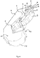
- Fig. 4 shows a sectional view of the charging plant according to the invention.
- the pouring 21, the loading tray 23 and the outlet opening 22 In addition, the support plate cylinder 4 in a retracted state and the pressure plate cylinder 6 can be seen in a retracted state.
- the cross member 8 support 13 which is integral with the mounting plate 10 for supporting the mounting rod 11 is executed.
- the holding element 9, which surrounds the cross member 8 in its circumferential direction and from which the mounting plates 10 protrude perpendicular to the longitudinal direction of the cross member 8.
- the side surface 7 has a support 13, which is formed integrally with the mounting plate 10.
- the integrally formed with the mounting plate 10 support 13 has an area through which the cross member 8 passes. Due to the sliding connection of the support 13 with the sliding block 14, a force dissipation of the pressure plate cylinder 6 can be effectively performed in the side surface 7 when performing a pressing operation of waste located in the charging tub 23. It is therefore possible the attachment of the support plate cylinder 4, which normally has to absorb the forces of the pressure plate cylinder 6, perform less stable and thus save total weight.
- the support 13 has the advantage that the side surface 7 must be made less massive, since any bending stresses occurring are absorbed by the support 13.
Landscapes
- Engineering & Computer Science (AREA)
- Mechanical Engineering (AREA)
- Refuse-Collection Vehicles (AREA)
Description
- Die vorliegende Erfindung betrifft ein Ladewerk für ein Abfallsammelfahrzeug.
- Das Ladewerk dient zum Aufnehmen, zum Verkleinern und zum Einbringen von Feststoffen in das Abfallsammelfahrzeug. Dazu ist es typischerweise am Heck eines Abfallsammelfahrzeugs angeordnet und weist eine Einschüttöffnung, eine Ladewanne und eine Austragsöffnung auf. Die Austragsöffnung ist typischerweise mit einem auf dem Abfallsammelfahrzeug befindlichen Behälter verbunden. Zum Zerkleinern der in das Ladewerk eingegebenen Gegenstände, umfasst das Ladewerk eine Pressvorrichtung, die eine Trägerplatte und eine Pressplatte umfasst. Dabei ist die Pressplatte schwenkbar an der Trägerplatte gelagert und kann sich zusammen mit der Trägerplatte bewegen.
- Die in das Abfallsammelfahrzeug einzubringenden Gegenstände werden in das Ladewerk bzw. in die Ladewanne befördert und dann mit Hilfe des Presswerks zerkleinert und an den Behälter des Abfallsammelfahrzeugs weitergegeben. Dabei wird zuerst die Trägerplatte, an deren der Ladewanne zugewandten Ende die Pressplatte angelenkt ist, in Richtung der Ladewanne verschoben, und im Anschluss daran durch eine Schwenkbewegung der Pressplatte die Gegenstände zerkleinert und/oder gepresst. Danach werden durch ein Zurückziehen der Trägerplatte die gepressten Gegenstände in das Behältnis des Abfallsammelfahrzeugs befördert.
- Da bei dem Pressvorgang große Kräfte auf das Ladewerk wirken, muss der Rahmen des Ladewerks besonders fest und verbindungssteif ausgeführt sein. Dies bedingt jedoch ein hohes Gewicht und führt damit zu hohen Betriebskosten eines Abfallsammelfahrzeugs mit einem solchen Ladewerk.
- Ziel der vorliegenden Erfindung ist es demnach, ein Ladewerk für ein Abfallsammelfahrzeug dahingehend fortzubilden, dass es bei gleichbleibender Stabilität weniger Gewicht aufweist.
- Dies wird durch das Ladewerk mit den Merkmalen nach dem Anspruch 1 erreicht.
- Demnach umfasst das erfindungsgemäße Ladewerk für ein Abfallsammelfahrzeug eine Rahmenstruktur des Ladewerks, eine Trägerplatte, die über einen Trägerplattenzylinder mit der Rahmenstruktur verbunden ist, und eine Pressplatte, die über einen Pressplattenzylinder mit dem Trägerplattenzylinder verbunden ist. Ferner ist das Ladewerk dadurch gekennzeichnet, dass der Trägerplattenzylinder in die tragende Struktur des Ladewerks eingebunden ist.
- Durch Einbinden des Trägerplattenzylinders in die tragende Struktur des Ladewerks weist der Trägerplattenzylinder eine stützende Wirkung auf. Dies trägt dazu bei, dass das Ladewerk an sich mit weniger robusten Bauteilen aufgebaut werden kann, ohne dabei die notwendigen Eigenschaften hinsichtlich Stabilität und Verbindungssteifigkeit zu verschlechtern.
- Vorzugsweise weist die Rahmenstruktur des Ladewerks zwei einander gegenüberliegende Seitenflächen und einen diese Seitenflächen verbindenden Querträger auf. Zudem ist der Querträger in seiner Umfangsrichtung von einem Halteelement umschlossen, das zur Längsrichtung des Querträgers etwa senkrecht abstehende Befestigungsplatten aufweist, zwischen denen eine zur Längsrichtung des Querträgers etwa parallel ausgerichtete Befestigungsstange gelagert ist. Vorzugsweise umschließt das Halteelement den Querträger nur teilweise. Dabei ist der Trägerplattenzylinder direkt mit der Befestigungsstange verbunden, wodurch dieser in die tragende Struktur des Ladewerks eingebunden ist. Vorzugsweise ist die Befestigungsstange in einem Abschnitt von einem aus dem Trägerplattenzylinder ragenden Ende eines Kolbens umschlossen.
- Diese Anordnung stellt eine besonders kompakte und wirkungsvolle Befestigung des Trägerplattenzylinders an dem Ladewerk bzw. der Rahmenstruktur des Ladewerks dar. Vorzugsweise umschließt das Halteelement den Querträger derart, dass eine zur Längsrichtung des Querträgers senkrechte Kraft über das Halteelement in die Struktur des Querträgers abgeleitet wird. Dabei ist es vorzuziehen, dass der Querträger eine Grundform aufweist, die bei einem Umschließen dieser Grundform eine Rotation um die Längsachse des Querträgers nicht zulässt.
- Nach einem weiteren optionalen vorteilhaften Merkmal der Erfindung ist der Trägerplattenzylinder zwischen zwei Seitenflächen des Ladewerks angeordnet.
- Darüber hinaus ist es von Vorteil, wenn mindestens eine von zwei Seitenflächen des Ladewerks an der zur anderen Seitenfläche zugewandten Seite eine Abstützung aufweist.
- Vorzugsweise ist die Abstützung ein zur Seitenfläche separates Element bspw. eine Leiste, das mit seiner flächigen Seite an die Seitenfläche angrenzt. Die Abstützung kann auch als Rippe angesehen werden, die auf einer ebenen Fläche der Seitenfläche angeordnet ist. Die Abstützung ist an der Seitenfläche befestigt. Alternativ kann die Abstützung auch eine aus der Seitenfläche herausragende Erhebung sein, die einstückig mit der Seitenfläche gebildet ist.
- Das Vorsehen dieser Abstützung ist vorteilhaft hinsichtlich der Ausführungen der Seitenflächen, da die Abstützung bei einer definierten Belastung Biegebeanspruchungen der Seitenflächen aufnehmen kann. Demnach kann durch die Abstützung die Seitenfläche an sich in einer geringeren Dicke ausgeführt werden. Dies führt im Endeffekt zu einem geringeren Gewicht des Ladewerks und zu einem geringeren Energieverbrauch eines Abfallsammelfahrzeugs mit dem Ladewerk.
- Nach einer weiteren vorteilhaften Ausführungsform der Erfindung dient die Abstützung zum Ableiten einer Kraft beim Ausfahren des Pressplattenzylinders. Vorzugsweise ist die Abstützung dazu ausgelegt, mit einem Gleitstein in einer Gleitverbindung zu stehen. Der Gleitstein ist dabei mit dem bewegbaren Teil des Trägerplattenzylinders in einer starren Verbindung. Vorteilhafterweise steht auch der nicht bewegbare Teil des Pressplattenzylinders in einer starren Verbindung mit dem Gleitstein.
- Typischerweise wird bei einem Ladevorgang durch das Ladewerk zuerst der Trägerplattenzylinder ausgefahren und der in die Ladewanne eingebrachte Abfall durch die Pressplatte gebrochen. Dies erfolgt durch die Bewegung der Trägerplatte, an dessen der Ladewanne zugewandten Ende die Pressplatte angelenkt ist. Durch die Bewegung der Trägerplatte bzw. der Pressplatte in Richtung der Ladewanne wird der darin angesammelte Abfall gebrochen. Um dies zu erreichen wird lediglich der Trägerplattenzylinder aus seiner eingefahrenen Position in eine ausgefahrene Position verfahren. Im Anschluss daran fährt der Pressplattenzylinder aus und verdichtet den Abfall mit Hilfe einer Schwenkbewegung, sodass der in der Ladewanne angesammelte Abfall gegen eine Ladewannenwand nahe einer Austragsöffnung gepresst wird. Dabei entstehen erhebliche Kräfte, die der Pressplattenzylinder aufbringen muss und auch in die Rahmenstruktur des Ladewerks einleiten muss. In einem letzten Schritt wird der Trägerplattenzylinder in seine eingefahrene Position zurückgefahren und der verdichtete Abfall durch eine Austragsöffnung befördert.
- Da der Pressplattenzylinder mit dem Trägerplattenzylinder verbunden ist und der Trägerplattenzylinder mit seinem beweglichen Teil über einen Gleitstein in einer Gleitverbindung mit der Abstützung steht, können die beim Pressvorgang wirkenden Kräfte über die Abstützung wirkungsvoll abgeleitet werden und müssen nicht über den Trägerplattenzylinder bzw. eine Halterung des Trägerplattenzylinders abgeleitet werden. In anderen Worten kann also die beim Pressvorgang wirkende Kraft des Pressplattenzylinders über einen Gleitstein an die Abstützung in die Seitenflächen geleitet werden. Dadurch kann die Anbindung des Trägerplattenzylinders an den Rahmen des Ladewerks in seinem Gewicht reduziert werden, da die beim Pressvorgang auftretenden Kräfte nicht vollständig über sie in die Rahmenstruktur des Ladewerks abgeleitet werden müssen. Insgesamt führt dies also zu einer Verminderung des Gewichts des Ladewerks.
- Nach einer weiteren optionalen Ausgestaltung der Erfindung weist die Rahmenstruktur des Ladewerks zwei einander gegenüberliegende Seitenflächen und einen diese Seitenflächen verbindenden Querträger auf, wobei der Querträger in seiner Umfangsrichtung von einem Halteelement umschlossen ist, das eine zur Längsrichtung des Querträgers etwa senkrecht abstehende Platte aufweist. Dabei ist die Abstützung einstückig mit dieser senkrecht abstehenden Platte ausgebildet.
- Durch das einstückige Ausformen der von dem Querträger senkrecht abstehenden Platte mit der Abstützung zur Aufnahme der im Pressvorgang auftretenden Kräfte wird eine besonders wirkungsvolle Umsetzung der erfinderischen Idee geschaffen. Insbesondere kann durch die Anbindung der Abstützung an der Querträger dort ebenfalls eine Krafteinleitung der bei einem Pressvorgang hervorgerufenen Kräfte erfolgen. Dabei werden zudem Synergieeffekte beim Herstellen der für das erfindungsgemäße Ladewerk benötigten Bauteile erzielt.
- Vorteilhafterweise ist vorgesehen, dass die einstückig mit der Abstützung ausgebildete Platte eine der Befestigungsplatten zum Befestigen der Befestigungsstange ist, vorzugsweise eine Ausnehmung aufweist, durch die der Querträger tritt.
- Vorzugsweise ist die Abstützung bogenförmig ausgebildet und weist eine zur Eintrittsöffnung konvexe Form bzw. eine zur Austrittsöffnung konkave Form auf.
- Die Erfindung betrifft zudem ein Abfallsammelfahrzeug mit einem Ladewerk nach einem der vorhergehenden Merkmalskombinationen.
- Nachfolgend wird die Erfindung anhand von Zeichnungen näher erläutert. Es zeigen:
- Fig. 1:
- eine isometrische Ansicht des erfindungsgemäßen Ladewerks,
- Fig. 2:
- eine Detailaufnahme des erfindungsgemäßen Ladewerks,
- Fig. 3:
- eine Detailaufnahme des erfindungsgemäßen Ladewerks, das eine Anbindung des Trägerplattenzylinders zeigt, und
- Fig. 4:
- eine Schnittansicht des erfindungsgemäßen Ladewerks.
-
Fig. 1 zeigt das erfindungsgemäße Ladewerk in einer Schrägansicht. Die Einschüttöffnung 21 dient zum Eingeben von Abfall oder anderen Gegenständen, die das Ladewerk verdichten und laden soll. Dazu werden die Gegenstände in die Ladewanne 23 eingelegt. Nach einem Befüllen der Ladewanne wird dann das Ladewerk betätigt, in dem der Trägerplattenzylinder 4, an dem die Trägerplatte 3 befestigt ist, ausgefahren wird. Da die Pressplatte 5 an dem der Ladewanne 23 zugewandten Ende der Trägerplatte 3 angeordnet ist, fährt die Pressplatte 5 mit der Bewegung der Trägerplatte ebenfalls in Richtung der Ladewanne 23 aus. - Dabei wird der in der Ladewanne 23 befindliche Abfall durch die Pressplatte 5 gebrochen. In einem ausgefahrenen Zustand des Trägerplattenzylinders 4 befindet sich die Pressplatte 5 nahe der Ladewanne 23. Dann erfolgt ein Betätigen des Pressplattenzylinders 6, der ein Schwenken der Pressplatte 5 um die Trägerplatte 3 hervorruft. Durch diese Schwenkbewegung wird der auf der Ladewanne 23 befindliche Abfall verdichtet bzw. gepresst. Danach wird der Trägerplattenzylinder 4 wieder in seinen eingefahrenen Zustand zurück gefahren, wodurch der komprimierte Abfall aus der Ladewanne 23 gehoben wird und einer Austrittsöffnung 22 (nicht dargestellt in
Figur 1 ) zugeführt wird. Nachdem erneut Abfall oder andere Gegenstände in die Ladewanne 23 durch die Einschüttöffnung 21 eingebracht worden sind, verfährt auch der Pressplattenzylinder 6 in seinen eingezogenen Zustand und das Ladewerk beginnt mit den vorstehend beschriebenen Arbeitsschritten von vorne. Dadurch wird das Zuführen von komprimiertem Abfall an die Austrittsöffnung schrittweise durchgeführt. - Man erkennt zudem die Rahmenstruktur 2 des Ladewerks 1 sowie zwei die Ladewanne 23 verbindende Seitenflächen 7. An einem der Ladewanne 23 gegenüberliegenden Ende der Seitenflächen 7 erstreckt sich ein Querträger 8, der die beiden Seitenflächen 7 miteinander verbindet. Typischerweise ist das Ladewerk 1 auch nahe des Querträgers 8 mit einem Abfallsammelfahrzeug verbunden.
- Darüber hinaus erkennt man Haltemittel 9, die den Querträger 8 in Bereichen nahe einer Seitenfläche 7 umschließen. Von dem Haltemittel 9 gehen zur Längsrichtung des Querträgers 8 senkrecht verlaufende Befestigungsplatten 10 ab, die jeweils Ausnehmungen aufweisen, in denen eine Befestigungsstange 11 gelagert ist. Die Befestigungsstange 11 ist in seiner Längsrichtung so ausgerichtet, dass sie in etwa der Längsrichtung des Querträgers 8 entspricht. Vorzugsweise ist die Querschnittsform des Querträgers 8 ein Rechteck mit abgerundeten Ecken. Ferner bildet die Befestigungsstange 11 einen Fixpunkt für den Trägerplattenzylinder 4, der mit einem an der Befestigungsstange 11 verbundenen Kolben fest mit der Rahmenstruktur 2 des Ladewerks 1 verbunden ist. Dadurch ist der Trägerplattenzylinder 4 in die tragende Struktur des Ladewerks 1 eingebunden und hat somit zudem eine stützende Wirkung. Der bewegbare Teil des Trägerplattenzylinders 4 ist mit dem Pressplattenzylinder 6 verbunden. Darüber hinaus umfasst der bewegbare Teil des Trägerplattenzylinders, also der nicht fest mit der Befestigungsstange 11 verbundene Kolben, eine starre Verbindung zu einem Gleitstein 14, der mit einer Abstützung 13 in einer Gleitverbindung steht. Die Abstützung 13 ist dabei ein zur Seitenfläche 7 separates Element, das an der Seitenfläche 7 angeordnet ist. Der Pressplattenzylinder 6 ist ebenfalls mit dem Gleitstein 14 über eine Verbindungsvorrichtung 16 verbunden.
-
Fig. 2 zeigt eine vergrößerte Darstellung der Abstützung 13 bei der aus Gründen der besseren Sichtbarkeit der Pressplattenzylinder 6 und der Trägerplattenzylinder 4 nicht dargestellt sind. Lediglich die Verbindungsvorrichtung 16 zwischen Trägerplattenzylinder 4 und Pressplattenzylinder 6, die den Gleitstein 14 umfasst, ist dargestellt. Dabei erkennt man auch die anderen Bauelemente wie den Querträger 8, das Halteelement 9, die Befestigungsplatte 10 und die Befestigungsstange 11. Die Verbindungsvorrichtung 16 bewegt sich mit einem Ausfähren des Trägerplattenzylinders 4, da sie an dem bewegbaren Teil des Trägerplattenzylinders 4 angeordnet ist. An der Verbindungsvorrichtung 16 ist der Pressplattenzylinder 6 befestigt, der mit seinem nicht bewegbaren Teil fest mit der Verbindungsvorrichtung 16 verbunden ist. Bewegt sich also der Pressplattenzylinder 6 erfolgt eine Schwenkbewegung der Pressplatte 5. Dabei wirkende Gegenkräfte, werden über den Pressplattenzylinder 6 an die Verbindungsvorrichtung 16 abgeleitet. Um zu verhindern, dass die beim Pressvorgang wirkenden Kräfte vollständig über die Befestigung des Trägerplattenzylinders 4 abgeleitet werden müssen, weist die Verbindungsvorrichtung 16 einen mit der Abstützung 13 in einer Gleitverbindung stehenden Gleitstein 14 auf. Dieser dient zum Ableiten der beim Ausfahren des Pressplattenzylinders 6 auftretenden Kräfte in die Abstützung 13 bzw. in die mit der Abstützung verbundenen Seitenwand 7 oder Querträger 8. -
Fig. 3 zeigt erneut eine vergrößerte Detailansicht des Ladewerks 1 diesmal jedoch mit einer Darstellung des Trägerplattenzylinders 4. Bei einem Ausfahren des Trägerplattenzylinders 4 erkennt man, dass der Gleitstein 14 entlang der Abstützung 13 weg von dem Querträger 8 gleitet. Dabei ist der an der Befestigungsstange 11 ortsfest angeordnete Kolben 12 des Trägerplattenzylinders 4 zu sehen, mit Hilfe dessen die bei einem Ausfahren des Trägerplattenzylinders 4 auftretenden Kräfte in die Rahmenstruktur des Ladewerks 1 abgeleitet werden. Der Gleitstein 14 dient nicht zur Bewegungsführung des Trägerplattenzylinders 4 bzw. der Trägerplatte 3. Dies wird durch eine an der Seitenfläche 7 angelenkte Kurbel 15 übernommen, die mit dem bewegbaren Ende des Trägerplattenzylinders 4 in Verbindung steht. - In einem ausgefahrenen Zustand des Trägerplattenzylinders 4 befindet sich der Gleitstein 14 in einem unteren Bereich der Abstützung 13. Mit einem unteren Bereich der Abstützung 13 ist ein von dem Querträger 8 beabstandeter Bereich der Abstützung 13 gemeint. Vorteilhaft an der Abstützung 13 und der Gleitverbindung mit dem Gleitstein 14 ist, dass der Pressplattenzylinder (in
Fig. 3 nicht dargestellt) seine bei einem Pressvorgang auftretenden Kräfte nicht vollständig durch die Halterung des Trägerplattenzylinders 4 ableiten muss. Vielmehr hilft die Gleitverbindung zwischen dem Gleitstein 14 und der Abstützung 13, um die auftretenden Kräfte in die Seitenflächen 7 abzuleiten. Dadurch kann die Verbindung des Trägerplattenzylinders 4 mit der Rahmenstruktur weniger massiv ausgestaltet werden. Zudem trägt die Abstützung 13 auch dazu bei, die ab einer definierten Belastung in den Seitenwänden auftretenden Biegebeanspruchungen aufzunehmen. Somit können auch die Seitenwände 7 des Ladewerks 1 mit weniger Material ausgeführt werden. -
Fig. 4 zeigt eine Schnittansicht des erfindungsgemäßen Ladewerks. Im unteren Bereich dieser Figur erkennt man die Einschüttöffnung 21, die Ladewanne 23 und die Austrittsöffnung 22. Zudem sind der Trägerplattenzylinder 4 in einem eingefahrenen Zustand und der Pressplattenzylinder 6 in einem eingefahrenen Zustand zu sehen. Man erkennt auch die von dem Querträger 8 abgehende Abstützung 13, die einstückig mit der Befestigungsplatte 10 zum Lagern der Befestigungsstange 11 ausgeführt ist. Auch erkennt man das Halteelement 9, das den Querträger 8 in seiner Umfangsrichtung umschließt und an von dem die Befestigungsplatten 10 senkrecht zur Längsrichtung des Querträgers 8 abstehen. Durch Einbinden des Trägerplattenzylinders 4 bzw. durch die Verbindung des Trägerplattenzylinders 4 mit dem Querträger 8 ist dieser in die tragende Struktur des Ladewerks 1 eingebunden. Darüber hinaus weist die Seitenfläche 7 eine Abstützung 13 auf, die einstückig mit der Befestigungsplatte 10 ausgebildet ist. Die einstückig mit der Befestigungsplatte 10 ausgebildete Abstützung 13 weist einen Bereich auf, durch den der Querträger 8 hindurch tritt. Durch die Gleitverbindung der Abstützung 13 mit dem Gleitstein 14 kann eine Kraftableitung des Pressplattenzylinders 6 bei einem Ausführen eines Pressvorgangs von in der Ladewanne 23 befindlichen Abfalls effektiv in die Seitenfläche 7 vorgenommen werden. Es ist demnach möglich die Befestigung des Trägerplattenzylinders 4, der normalerweise die Kräfte des Pressplattenzylinders 6 aufnehmen muss, weniger stabil auszuführen und somit insgesamt Gewicht einzusparen. Zudem weist die Abstützung 13 den Vorteil auf, dass die Seitenfläche 7 weniger massiv ausgebildet werden muss, da etwaige auftretende Biegebeanspruchungen durch die Abstützung 13 aufgenommen werden.
Claims (10)
- Ladewerk (1) für ein Abfallsammelfahrzeug, umfassend:eine Rahmenstruktur (2) des Ladewerks (1),eine Trägerplatte (3), die über einen Trägerplattenzylinder (4) mit der Rahmenstruktur (2) verbunden ist, undeine Pressplatte (5), die über einen Pressplattenzylinder (6) mit dem Trägerplattenzylinder (4) verbunden ist,dadurch gekennzeichnet, dassder Trägerplattenzylinder (4) in die tragende Struktur des Ladewerks (1) eingebunden ist.
- Ladewerk (1) nach Anspruch 1, wobei
die Rahmenstruktur (2) zwei einander gegenüberliegende Seitenflächen (7) und einen diese Seitenflächen (7) verbindenden Querträger (8) aufweist,
der Querträger (8) in seiner Umfangsrichtung von einem Halteelement (9) umschlossen ist, das zur Längsrichtung des Querträgers (8) etwa senkrecht abstehende Befestigungsplatten (10) aufweist, zwischen denen eine zur Längsrichtung des Querträgers (8) etwa parallele Befestigungsstange (11) gelagert ist, und
der Trägerplattenzylinder (4) direkt mit der Befestigungsstange (11) verbunden ist, vorzugsweise die Befestigungsstange (11) von einem aus dem Trägerplattenzylinder (4) ragenden Ende eines Kolbens (12) umschlossen ist. - Ladewerk (1) nach einem der vorhergehenden Ansprüche, wobei der Trägerplattenzylinder (4) zwischen zwei Seitenflächen (7) des Ladewerks (1) angeordnet ist.
- Ladewerk (1) nach einem der vorhergehenden Ansprüche, wobei mindestens eine von zwei Seitenflächen (7) des Ladewerks (1) an der zur anderen Seitenfläche (7) zugewandten Seite eine Abstützung (13) aufweist.
- Ladewerk (1) nach Anspruch 4, wobei die Abstützung (13) ein zur Seitenfläche (7) separates Element ist, das mit seiner flächigen Seite an die Seitenfläche (7) angrenzt.
- Ladewerk (1) nach Anspruch 4 oder 5, wobei die Abstützung (13) zum Ableiten einer Kraft beim Ausfahren des des Pressplattenzylinders (6) dient und vorzugsweise dazu ausgelegt ist, Gleitstein (14) in einer Gleitverbindung zu stehen, wobei der Gleitstein (14) mit dem bewegbaren Teil des Trägerplattenzylinders (4) und mit dem nicht bewegbaren Teil des Pressplattenzylinders (6) in einer starren Verbindung steht.
- Ladewerk (1) nach einem der Ansprüche 4 bis 6, wobei
die Rahmenstruktur (2) zwei einander gegenüberliegende Seitenflächen (7) und einen diese Seitenflächen (7) verbindenden Querträger (8) aufweist,
der Querträger (8) in seiner Umfangsrichtung von einem Halteelement (9) umschlossen ist, das eine zur Längsrichtung des Querträgers (8) etwa senkrecht abstehende Platte (10) aufweist, und
die Abstützung (13) einstückig mit der senkrecht abstehenden Platte (10) ausgebildet ist. - Ladewerk (1) nach Anspruch 2 und 7, wobei die einstückig mit der Abstützung (13) ausgebildete Platte (10) eine der Befestigungsplatten (10) ist und vorzugsweise eine Ausnehmung aufweist, durch die der Querträger (8) tritt.
- Ladewerk (1) nach einem der Ansprüche 4 bis 8, wobei die Abstützung (13) bogenförmig ausgebildet ist.
- Abfallsammelfahrzeug mit einem Ladewerk (1) nach einem der vorhergehenden Ansprüche.
Priority Applications (2)
| Application Number | Priority Date | Filing Date | Title |
|---|---|---|---|
| PL15200760T PL3078614T3 (pl) | 2015-04-10 | 2015-12-17 | Mechanizm załadowczy dla pojazdu do zbiórki odpadów |
| HRP20180097TT HRP20180097T1 (hr) | 2015-04-10 | 2018-01-18 | Mehanizam za utovar za vozila za sakupljanje otpada |
Applications Claiming Priority (1)
| Application Number | Priority Date | Filing Date | Title |
|---|---|---|---|
| DE202015002700.8U DE202015002700U1 (de) | 2015-04-10 | 2015-04-10 | Ladewerk für ein Abfallsammelfahrzeug |
Publications (2)
| Publication Number | Publication Date |
|---|---|
| EP3078614A1 true EP3078614A1 (de) | 2016-10-12 |
| EP3078614B1 EP3078614B1 (de) | 2017-10-18 |
Family
ID=55129407
Family Applications (1)
| Application Number | Title | Priority Date | Filing Date |
|---|---|---|---|
| EP15200760.5A Active EP3078614B1 (de) | 2015-04-10 | 2015-12-17 | Ladewerk für ein abfallsammelfahrzeug |
Country Status (7)
| Country | Link |
|---|---|
| EP (1) | EP3078614B1 (de) |
| DE (1) | DE202015002700U1 (de) |
| DK (1) | DK3078614T3 (de) |
| ES (1) | ES2656205T3 (de) |
| HR (1) | HRP20180097T1 (de) |
| PL (1) | PL3078614T3 (de) |
| PT (1) | PT3078614T (de) |
Citations (4)
| Publication number | Priority date | Publication date | Assignee | Title |
|---|---|---|---|---|
| US3143230A (en) * | 1960-05-09 | 1964-08-04 | Leach Corp | Refuse vehicle |
| US3682336A (en) * | 1971-03-17 | 1972-08-08 | Heil Co | Refuse body loading mechanism |
| DE202011103627U1 (de) * | 2011-07-21 | 2011-11-07 | Zöller-Kipper GmbH | Müllsammelbehälter mit einer Press- und Verdichtungseinrichtung |
| WO2013120353A1 (zh) * | 2012-02-15 | 2013-08-22 | 中联重科股份有限公司 | 填装器以及后装压缩式垃圾车 |
-
2015
- 2015-04-10 DE DE202015002700.8U patent/DE202015002700U1/de not_active Expired - Lifetime
- 2015-12-17 PT PT152007605T patent/PT3078614T/pt unknown
- 2015-12-17 DK DK15200760.5T patent/DK3078614T3/da active
- 2015-12-17 ES ES15200760.5T patent/ES2656205T3/es active Active
- 2015-12-17 PL PL15200760T patent/PL3078614T3/pl unknown
- 2015-12-17 EP EP15200760.5A patent/EP3078614B1/de active Active
-
2018
- 2018-01-18 HR HRP20180097TT patent/HRP20180097T1/hr unknown
Patent Citations (4)
| Publication number | Priority date | Publication date | Assignee | Title |
|---|---|---|---|---|
| US3143230A (en) * | 1960-05-09 | 1964-08-04 | Leach Corp | Refuse vehicle |
| US3682336A (en) * | 1971-03-17 | 1972-08-08 | Heil Co | Refuse body loading mechanism |
| DE202011103627U1 (de) * | 2011-07-21 | 2011-11-07 | Zöller-Kipper GmbH | Müllsammelbehälter mit einer Press- und Verdichtungseinrichtung |
| WO2013120353A1 (zh) * | 2012-02-15 | 2013-08-22 | 中联重科股份有限公司 | 填装器以及后装压缩式垃圾车 |
Also Published As
| Publication number | Publication date |
|---|---|
| PL3078614T3 (pl) | 2018-03-30 |
| EP3078614B1 (de) | 2017-10-18 |
| ES2656205T3 (es) | 2018-02-26 |
| DE202015002700U1 (de) | 2016-07-13 |
| HRP20180097T1 (hr) | 2018-02-23 |
| PT3078614T (pt) | 2018-01-11 |
| DK3078614T3 (da) | 2017-11-27 |
Similar Documents
| Publication | Publication Date | Title |
|---|---|---|
| DE2535998B2 (de) | Müllfahrzeug mit Frontlader | |
| DE1247937B (de) | Transportfahrzeug fuer Schuettgut wie Muell od. dgl. | |
| EP3700696B1 (de) | Presse für eine giessmaschine und giessmaschine | |
| DE2634811A1 (de) | Vorrichtung zum zerschneiden bzw. brechen und zusammenpressen von schrott | |
| WO1995031388A1 (de) | Müllsammelfahrzeug | |
| EP3078614B1 (de) | Ladewerk für ein abfallsammelfahrzeug | |
| DE102018133264B4 (de) | Paketierpresse und Verfahren zum Paketieren von verformbarem Material | |
| EP3385177A1 (de) | Verpackungsmaschine mit neigbarer werkzeugschublade | |
| EP2283999A2 (de) | Ballenpresse | |
| WO2017032363A1 (de) | Einheit zum zerkleinern von material mittels eines querstromzerspaners | |
| DE1232517B (de) | Vorrichtung zum Beladen von Muellsammel-behaeltern | |
| DE202009011722U1 (de) | Presscontainer | |
| DE10017315C2 (de) | Vorrichtung zur bewegbaren Lagerung eines oberen Formwerkzeugs | |
| EP2735370B1 (de) | Schleißteilwechselvorrichtung | |
| DE20000912U1 (de) | Aus einem Schneckenverdichter und einem Preßbehälter bestehende Anordnung zur Aufnahme von zu verpressenden Abfallstoffen | |
| EP3415305A1 (de) | Stationäre abfallpresseneinheit zur verbindung mit einem mobilen wechselcontainer | |
| DE202004012261U1 (de) | Aufspannplatte für Spritzgießmaschinen | |
| DE2115667B2 (de) | Verpackungsvorrichtung für Abfallpresspakete | |
| DE4226978A1 (de) | Containerpresse | |
| DE1219387B (de) | Muellfahrzeug | |
| DE102016118985A1 (de) | Reisigpresse | |
| DE10201047B4 (de) | Strangpresse und Verfahren zum Strangpressen | |
| DE29622494U1 (de) | Vorrichtung zum Verdichten von Müll in Haushaltsmülltonnen | |
| DE2030915C3 (de) | Vorrichtung zum Pressen von paketfähigen losen Gut, insbesondere Müll | |
| EP4701819A1 (de) | Auffangbehältnis für werkstückpartikel, baugruppe umfassend ein motorisch angetriebenes handwerkzeug und ein auffangbehältnis, motorisch angetriebenes handwerkzeug, sowie verfahren |
Legal Events
| Date | Code | Title | Description |
|---|---|---|---|
| PUAI | Public reference made under article 153(3) epc to a published international application that has entered the european phase |
Free format text: ORIGINAL CODE: 0009012 |
|
| AK | Designated contracting states |
Kind code of ref document: A1 Designated state(s): AL AT BE BG CH CY CZ DE DK EE ES FI FR GB GR HR HU IE IS IT LI LT LU LV MC MK MT NL NO PL PT RO RS SE SI SK SM TR |
|
| AX | Request for extension of the european patent |
Extension state: BA ME |
|
| 17P | Request for examination filed |
Effective date: 20170215 |
|
| GRAP | Despatch of communication of intention to grant a patent |
Free format text: ORIGINAL CODE: EPIDOSNIGR1 |
|
| INTG | Intention to grant announced |
Effective date: 20170512 |
|
| GRAS | Grant fee paid |
Free format text: ORIGINAL CODE: EPIDOSNIGR3 |
|
| GRAA | (expected) grant |
Free format text: ORIGINAL CODE: 0009210 |
|
| AK | Designated contracting states |
Kind code of ref document: B1 Designated state(s): AL AT BE BG CH CY CZ DE DK EE ES FI FR GB GR HR HU IE IS IT LI LT LU LV MC MK MT NL NO PL PT RO RS SE SI SK SM TR |
|
| REG | Reference to a national code |
Ref country code: GB Ref legal event code: FG4D Free format text: NOT ENGLISH |
|
| REG | Reference to a national code |
Ref country code: CH Ref legal event code: EP Ref country code: CH Ref legal event code: NV Representative=s name: KELLER AND PARTNER PATENTANWAELTE AG, CH |
|
| REG | Reference to a national code |
Ref country code: SE Ref legal event code: TRGR |
|
| REG | Reference to a national code |
Ref country code: AT Ref legal event code: REF Ref document number: 937729 Country of ref document: AT Kind code of ref document: T Effective date: 20171115 Ref country code: IE Ref legal event code: FG4D Free format text: LANGUAGE OF EP DOCUMENT: GERMAN |
|
| REG | Reference to a national code |
Ref country code: DK Ref legal event code: T3 Effective date: 20171121 |
|
| REG | Reference to a national code |
Ref country code: DE Ref legal event code: R096 Ref document number: 502015002141 Country of ref document: DE |
|
| REG | Reference to a national code |
Ref country code: FR Ref legal event code: PLFP Year of fee payment: 3 |
|
| REG | Reference to a national code |
Ref country code: PT Ref legal event code: SC4A Ref document number: 3078614 Country of ref document: PT Date of ref document: 20180111 Kind code of ref document: T Free format text: AVAILABILITY OF NATIONAL TRANSLATION Effective date: 20180105 |
|
| REG | Reference to a national code |
Ref country code: HR Ref legal event code: TUEP Ref document number: P20180097 Country of ref document: HR |
|
| REG | Reference to a national code |
Ref country code: NL Ref legal event code: FP |
|
| REG | Reference to a national code |
Ref country code: HR Ref legal event code: T1PR Ref document number: P20180097 Country of ref document: HR |
|
| REG | Reference to a national code |
Ref country code: ES Ref legal event code: FG2A Ref document number: 2656205 Country of ref document: ES Kind code of ref document: T3 Effective date: 20180226 |
|
| REG | Reference to a national code |
Ref country code: LT Ref legal event code: MG4D |
|
| PG25 | Lapsed in a contracting state [announced via postgrant information from national office to epo] |
Ref country code: FI Free format text: LAPSE BECAUSE OF FAILURE TO SUBMIT A TRANSLATION OF THE DESCRIPTION OR TO PAY THE FEE WITHIN THE PRESCRIBED TIME-LIMIT Effective date: 20171018 Ref country code: LT Free format text: LAPSE BECAUSE OF FAILURE TO SUBMIT A TRANSLATION OF THE DESCRIPTION OR TO PAY THE FEE WITHIN THE PRESCRIBED TIME-LIMIT Effective date: 20171018 Ref country code: NO Free format text: LAPSE BECAUSE OF FAILURE TO SUBMIT A TRANSLATION OF THE DESCRIPTION OR TO PAY THE FEE WITHIN THE PRESCRIBED TIME-LIMIT Effective date: 20180118 |
|
| PG25 | Lapsed in a contracting state [announced via postgrant information from national office to epo] |
Ref country code: GR Free format text: LAPSE BECAUSE OF FAILURE TO SUBMIT A TRANSLATION OF THE DESCRIPTION OR TO PAY THE FEE WITHIN THE PRESCRIBED TIME-LIMIT Effective date: 20180119 Ref country code: LV Free format text: LAPSE BECAUSE OF FAILURE TO SUBMIT A TRANSLATION OF THE DESCRIPTION OR TO PAY THE FEE WITHIN THE PRESCRIBED TIME-LIMIT Effective date: 20171018 Ref country code: BG Free format text: LAPSE BECAUSE OF FAILURE TO SUBMIT A TRANSLATION OF THE DESCRIPTION OR TO PAY THE FEE WITHIN THE PRESCRIBED TIME-LIMIT Effective date: 20180118 Ref country code: RS Free format text: LAPSE BECAUSE OF FAILURE TO SUBMIT A TRANSLATION OF THE DESCRIPTION OR TO PAY THE FEE WITHIN THE PRESCRIBED TIME-LIMIT Effective date: 20171018 Ref country code: IS Free format text: LAPSE BECAUSE OF FAILURE TO SUBMIT A TRANSLATION OF THE DESCRIPTION OR TO PAY THE FEE WITHIN THE PRESCRIBED TIME-LIMIT Effective date: 20180218 |
|
| REG | Reference to a national code |
Ref country code: DE Ref legal event code: R097 Ref document number: 502015002141 Country of ref document: DE |
|
| PG25 | Lapsed in a contracting state [announced via postgrant information from national office to epo] |
Ref country code: SK Free format text: LAPSE BECAUSE OF FAILURE TO SUBMIT A TRANSLATION OF THE DESCRIPTION OR TO PAY THE FEE WITHIN THE PRESCRIBED TIME-LIMIT Effective date: 20171018 Ref country code: EE Free format text: LAPSE BECAUSE OF FAILURE TO SUBMIT A TRANSLATION OF THE DESCRIPTION OR TO PAY THE FEE WITHIN THE PRESCRIBED TIME-LIMIT Effective date: 20171018 |
|
| PLBE | No opposition filed within time limit |
Free format text: ORIGINAL CODE: 0009261 |
|
| STAA | Information on the status of an ep patent application or granted ep patent |
Free format text: STATUS: NO OPPOSITION FILED WITHIN TIME LIMIT |
|
| PG25 | Lapsed in a contracting state [announced via postgrant information from national office to epo] |
Ref country code: RO Free format text: LAPSE BECAUSE OF FAILURE TO SUBMIT A TRANSLATION OF THE DESCRIPTION OR TO PAY THE FEE WITHIN THE PRESCRIBED TIME-LIMIT Effective date: 20171018 Ref country code: SM Free format text: LAPSE BECAUSE OF FAILURE TO SUBMIT A TRANSLATION OF THE DESCRIPTION OR TO PAY THE FEE WITHIN THE PRESCRIBED TIME-LIMIT Effective date: 20171018 |
|
| 26N | No opposition filed |
Effective date: 20180719 |
|
| PG25 | Lapsed in a contracting state [announced via postgrant information from national office to epo] |
Ref country code: MT Free format text: LAPSE BECAUSE OF FAILURE TO SUBMIT A TRANSLATION OF THE DESCRIPTION OR TO PAY THE FEE WITHIN THE PRESCRIBED TIME-LIMIT Effective date: 20171018 |
|
| PG25 | Lapsed in a contracting state [announced via postgrant information from national office to epo] |
Ref country code: SI Free format text: LAPSE BECAUSE OF FAILURE TO SUBMIT A TRANSLATION OF THE DESCRIPTION OR TO PAY THE FEE WITHIN THE PRESCRIBED TIME-LIMIT Effective date: 20171018 |
|
| REG | Reference to a national code |
Ref country code: HR Ref legal event code: ODRP Ref document number: P20180097 Country of ref document: HR Payment date: 20181120 Year of fee payment: 4 |
|
| PG25 | Lapsed in a contracting state [announced via postgrant information from national office to epo] |
Ref country code: MC Free format text: LAPSE BECAUSE OF FAILURE TO SUBMIT A TRANSLATION OF THE DESCRIPTION OR TO PAY THE FEE WITHIN THE PRESCRIBED TIME-LIMIT Effective date: 20171018 Ref country code: HU Free format text: LAPSE BECAUSE OF FAILURE TO SUBMIT A TRANSLATION OF THE DESCRIPTION OR TO PAY THE FEE WITHIN THE PRESCRIBED TIME-LIMIT; INVALID AB INITIO Effective date: 20151217 |
|
| PG25 | Lapsed in a contracting state [announced via postgrant information from national office to epo] |
Ref country code: CY Free format text: LAPSE BECAUSE OF FAILURE TO SUBMIT A TRANSLATION OF THE DESCRIPTION OR TO PAY THE FEE WITHIN THE PRESCRIBED TIME-LIMIT Effective date: 20171018 |
|
| PG25 | Lapsed in a contracting state [announced via postgrant information from national office to epo] |
Ref country code: MK Free format text: LAPSE BECAUSE OF FAILURE TO SUBMIT A TRANSLATION OF THE DESCRIPTION OR TO PAY THE FEE WITHIN THE PRESCRIBED TIME-LIMIT Effective date: 20171018 |
|
| REG | Reference to a national code |
Ref country code: HR Ref legal event code: ODRP Ref document number: P20180097 Country of ref document: HR Payment date: 20191126 Year of fee payment: 5 |
|
| PG25 | Lapsed in a contracting state [announced via postgrant information from national office to epo] |
Ref country code: AL Free format text: LAPSE BECAUSE OF FAILURE TO SUBMIT A TRANSLATION OF THE DESCRIPTION OR TO PAY THE FEE WITHIN THE PRESCRIBED TIME-LIMIT Effective date: 20171018 |
|
| REG | Reference to a national code |
Ref country code: CH Ref legal event code: PFA Owner name: FAUN UMWELTTECHNIK GMBH AND CO. KG, DE Free format text: FORMER OWNER: FAUN UMWELTTECHNIK GMBH AND CO. KG, DE |
|
| REG | Reference to a national code |
Ref country code: HR Ref legal event code: ODRP Ref document number: P20180097 Country of ref document: HR Payment date: 20201124 Year of fee payment: 6 |
|
| PGFP | Annual fee paid to national office [announced via postgrant information from national office to epo] |
Ref country code: AT Payment date: 20201221 Year of fee payment: 6 |
|
| REG | Reference to a national code |
Ref country code: HR Ref legal event code: ODRP Ref document number: P20180097 Country of ref document: HR Payment date: 20211209 Year of fee payment: 7 |
|
| REG | Reference to a national code |
Ref country code: AT Ref legal event code: MM01 Ref document number: 937729 Country of ref document: AT Kind code of ref document: T Effective date: 20211217 |
|
| PG25 | Lapsed in a contracting state [announced via postgrant information from national office to epo] |
Ref country code: AT Free format text: LAPSE BECAUSE OF NON-PAYMENT OF DUE FEES Effective date: 20211217 |
|
| REG | Reference to a national code |
Ref country code: HR Ref legal event code: ODRP Ref document number: P20180097 Country of ref document: HR Payment date: 20221212 Year of fee payment: 8 |
|
| PGFP | Annual fee paid to national office [announced via postgrant information from national office to epo] |
Ref country code: SE Payment date: 20221221 Year of fee payment: 8 Ref country code: PT Payment date: 20221207 Year of fee payment: 8 Ref country code: NL Payment date: 20221220 Year of fee payment: 8 Ref country code: LU Payment date: 20221219 Year of fee payment: 8 Ref country code: IE Payment date: 20221219 Year of fee payment: 8 Ref country code: GB Payment date: 20221222 Year of fee payment: 8 Ref country code: FR Payment date: 20221219 Year of fee payment: 8 Ref country code: DK Payment date: 20221221 Year of fee payment: 8 Ref country code: CZ Payment date: 20221205 Year of fee payment: 8 |
|
| PGFP | Annual fee paid to national office [announced via postgrant information from national office to epo] |
Ref country code: PL Payment date: 20221207 Year of fee payment: 8 Ref country code: HR Payment date: 20221212 Year of fee payment: 8 Ref country code: BE Payment date: 20221220 Year of fee payment: 8 |
|
| PGFP | Annual fee paid to national office [announced via postgrant information from national office to epo] |
Ref country code: TR Payment date: 20221214 Year of fee payment: 8 Ref country code: ES Payment date: 20230119 Year of fee payment: 8 Ref country code: CH Payment date: 20230103 Year of fee payment: 8 |
|
| PGFP | Annual fee paid to national office [announced via postgrant information from national office to epo] |
Ref country code: IT Payment date: 20221230 Year of fee payment: 8 Ref country code: DE Payment date: 20221221 Year of fee payment: 8 |
|
| P01 | Opt-out of the competence of the unified patent court (upc) registered |
Effective date: 20230602 |
|
| REG | Reference to a national code |
Ref country code: HR Ref legal event code: PBON Ref document number: P20180097 Country of ref document: HR Effective date: 20231217 |
|
| REG | Reference to a national code |
Ref country code: DE Ref legal event code: R119 Ref document number: 502015002141 Country of ref document: DE |
|
| REG | Reference to a national code |
Ref country code: DK Ref legal event code: EBP Effective date: 20231231 |
|
| PG25 | Lapsed in a contracting state [announced via postgrant information from national office to epo] |
Ref country code: CZ Free format text: LAPSE BECAUSE OF NON-PAYMENT OF DUE FEES Effective date: 20231217 |
|
| REG | Reference to a national code |
Ref country code: SE Ref legal event code: EUG |
|
| PG25 | Lapsed in a contracting state [announced via postgrant information from national office to epo] |
Ref country code: CZ Free format text: LAPSE BECAUSE OF NON-PAYMENT OF DUE FEES Effective date: 20231217 |
|
| REG | Reference to a national code |
Ref country code: CH Ref legal event code: PL |
|
| PG25 | Lapsed in a contracting state [announced via postgrant information from national office to epo] |
Ref country code: PT Free format text: LAPSE BECAUSE OF NON-PAYMENT OF DUE FEES Effective date: 20240617 |
|
| REG | Reference to a national code |
Ref country code: NL Ref legal event code: MM Effective date: 20240101 |
|
| PG25 | Lapsed in a contracting state [announced via postgrant information from national office to epo] |
Ref country code: LU Free format text: LAPSE BECAUSE OF NON-PAYMENT OF DUE FEES Effective date: 20231217 |
|
| GBPC | Gb: european patent ceased through non-payment of renewal fee |
Effective date: 20231217 |
|
| REG | Reference to a national code |
Ref country code: BE Ref legal event code: MM Effective date: 20231231 |
|
| PG25 | Lapsed in a contracting state [announced via postgrant information from national office to epo] |
Ref country code: PT Free format text: LAPSE BECAUSE OF NON-PAYMENT OF DUE FEES Effective date: 20240617 Ref country code: LU Free format text: LAPSE BECAUSE OF NON-PAYMENT OF DUE FEES Effective date: 20231217 |
|
| PG25 | Lapsed in a contracting state [announced via postgrant information from national office to epo] |
Ref country code: NL Free format text: LAPSE BECAUSE OF NON-PAYMENT OF DUE FEES Effective date: 20240101 |
|
| PG25 | Lapsed in a contracting state [announced via postgrant information from national office to epo] |
Ref country code: NL Free format text: LAPSE BECAUSE OF NON-PAYMENT OF DUE FEES Effective date: 20240101 |
|
| REG | Reference to a national code |
Ref country code: IE Ref legal event code: MM4A |
|
| PG25 | Lapsed in a contracting state [announced via postgrant information from national office to epo] |
Ref country code: HR Free format text: LAPSE BECAUSE OF NON-PAYMENT OF DUE FEES Effective date: 20231217 Ref country code: DE Free format text: LAPSE BECAUSE OF NON-PAYMENT OF DUE FEES Effective date: 20240702 Ref country code: IE Free format text: LAPSE BECAUSE OF NON-PAYMENT OF DUE FEES Effective date: 20231217 |
|
| PG25 | Lapsed in a contracting state [announced via postgrant information from national office to epo] |
Ref country code: GB Free format text: LAPSE BECAUSE OF NON-PAYMENT OF DUE FEES Effective date: 20231217 |
|
| PG25 | Lapsed in a contracting state [announced via postgrant information from national office to epo] |
Ref country code: BE Free format text: LAPSE BECAUSE OF NON-PAYMENT OF DUE FEES Effective date: 20231231 |
|
| PG25 | Lapsed in a contracting state [announced via postgrant information from national office to epo] |
Ref country code: FR Free format text: LAPSE BECAUSE OF NON-PAYMENT OF DUE FEES Effective date: 20231231 |
|
| PG25 | Lapsed in a contracting state [announced via postgrant information from national office to epo] |
Ref country code: CH Free format text: LAPSE BECAUSE OF NON-PAYMENT OF DUE FEES Effective date: 20231231 |
|
| PG25 | Lapsed in a contracting state [announced via postgrant information from national office to epo] |
Ref country code: IE Free format text: LAPSE BECAUSE OF NON-PAYMENT OF DUE FEES Effective date: 20231217 Ref country code: HR Free format text: LAPSE BECAUSE OF NON-PAYMENT OF DUE FEES Effective date: 20231217 Ref country code: GB Free format text: LAPSE BECAUSE OF NON-PAYMENT OF DUE FEES Effective date: 20231217 Ref country code: FR Free format text: LAPSE BECAUSE OF NON-PAYMENT OF DUE FEES Effective date: 20231231 Ref country code: DE Free format text: LAPSE BECAUSE OF NON-PAYMENT OF DUE FEES Effective date: 20240702 Ref country code: CH Free format text: LAPSE BECAUSE OF NON-PAYMENT OF DUE FEES Effective date: 20231231 Ref country code: BE Free format text: LAPSE BECAUSE OF NON-PAYMENT OF DUE FEES Effective date: 20231231 |
|
| PG25 | Lapsed in a contracting state [announced via postgrant information from national office to epo] |
Ref country code: DK Free format text: LAPSE BECAUSE OF NON-PAYMENT OF DUE FEES Effective date: 20231231 |
|
| PG25 | Lapsed in a contracting state [announced via postgrant information from national office to epo] |
Ref country code: DK Free format text: LAPSE BECAUSE OF NON-PAYMENT OF DUE FEES Effective date: 20231231 |
|
| REG | Reference to a national code |
Ref country code: ES Ref legal event code: FD2A Effective date: 20250131 |
|
| PG25 | Lapsed in a contracting state [announced via postgrant information from national office to epo] |
Ref country code: ES Free format text: LAPSE BECAUSE OF NON-PAYMENT OF DUE FEES Effective date: 20231218 |
|
| PG25 | Lapsed in a contracting state [announced via postgrant information from national office to epo] |
Ref country code: PL Free format text: LAPSE BECAUSE OF NON-PAYMENT OF DUE FEES Effective date: 20231217 |
|
| PG25 | Lapsed in a contracting state [announced via postgrant information from national office to epo] |
Ref country code: IT Free format text: LAPSE BECAUSE OF NON-PAYMENT OF DUE FEES Effective date: 20231217 |
|
| PG25 | Lapsed in a contracting state [announced via postgrant information from national office to epo] |
Ref country code: SE Free format text: LAPSE BECAUSE OF NON-PAYMENT OF DUE FEES Effective date: 20231218 |