EP3078622A1 - Appareil et procédé de détection et de protection de cylindre à huile télescopique de grue - Google Patents
Appareil et procédé de détection et de protection de cylindre à huile télescopique de grue Download PDFInfo
- Publication number
- EP3078622A1 EP3078622A1 EP14872677.1A EP14872677A EP3078622A1 EP 3078622 A1 EP3078622 A1 EP 3078622A1 EP 14872677 A EP14872677 A EP 14872677A EP 3078622 A1 EP3078622 A1 EP 3078622A1
- Authority
- EP
- European Patent Office
- Prior art keywords
- cavity
- oil
- small
- oil cylinder
- telescopic
- Prior art date
- Legal status (The legal status is an assumption and is not a legal conclusion. Google has not performed a legal analysis and makes no representation as to the accuracy of the status listed.)
- Withdrawn
Links
- 238000000034 method Methods 0.000 title claims abstract description 39
- 239000003921 oil Substances 0.000 claims abstract description 422
- 239000010720 hydraulic oil Substances 0.000 claims abstract description 17
- 230000008859 change Effects 0.000 claims abstract description 14
- 230000002159 abnormal effect Effects 0.000 claims description 34
- 230000005856 abnormality Effects 0.000 claims description 14
- 238000006073 displacement reaction Methods 0.000 claims description 8
- 230000001105 regulatory effect Effects 0.000 description 14
- 238000011282 treatment Methods 0.000 description 13
- 230000008569 process Effects 0.000 description 11
- 238000010586 diagram Methods 0.000 description 6
- 238000001514 detection method Methods 0.000 description 5
- 230000001276 controlling effect Effects 0.000 description 4
- 238000005457 optimization Methods 0.000 description 4
- 230000005484 gravity Effects 0.000 description 3
- 238000012423 maintenance Methods 0.000 description 3
- 238000005461 lubrication Methods 0.000 description 2
- 238000012545 processing Methods 0.000 description 2
- 238000012360 testing method Methods 0.000 description 2
- 230000001133 acceleration Effects 0.000 description 1
- 230000009471 action Effects 0.000 description 1
- 230000009286 beneficial effect Effects 0.000 description 1
- 238000007664 blowing Methods 0.000 description 1
- 230000000694 effects Effects 0.000 description 1
- 238000005516 engineering process Methods 0.000 description 1
- 230000014509 gene expression Effects 0.000 description 1
- 238000007689 inspection Methods 0.000 description 1
- 230000007246 mechanism Effects 0.000 description 1
- 238000012986 modification Methods 0.000 description 1
- 230000004048 modification Effects 0.000 description 1
- 230000003449 preventive effect Effects 0.000 description 1
- 230000008439 repair process Effects 0.000 description 1
- 238000000926 separation method Methods 0.000 description 1
Images


Classifications
-
- B—PERFORMING OPERATIONS; TRANSPORTING
- B66—HOISTING; LIFTING; HAULING
- B66C—CRANES; LOAD-ENGAGING ELEMENTS OR DEVICES FOR CRANES, CAPSTANS, WINCHES, OR TACKLES
- B66C23/00—Cranes comprising essentially a beam, boom, or triangular structure acting as a cantilever and mounted for translatory of swinging movements in vertical or horizontal planes or a combination of such movements, e.g. jib-cranes, derricks, tower cranes
- B66C23/62—Constructional features or details
- B66C23/64—Jibs
- B66C23/68—Jibs foldable or otherwise adjustable in configuration
-
- B—PERFORMING OPERATIONS; TRANSPORTING
- B66—HOISTING; LIFTING; HAULING
- B66C—CRANES; LOAD-ENGAGING ELEMENTS OR DEVICES FOR CRANES, CAPSTANS, WINCHES, OR TACKLES
- B66C23/00—Cranes comprising essentially a beam, boom, or triangular structure acting as a cantilever and mounted for translatory of swinging movements in vertical or horizontal planes or a combination of such movements, e.g. jib-cranes, derricks, tower cranes
- B66C23/62—Constructional features or details
- B66C23/64—Jibs
- B66C23/70—Jibs constructed of sections adapted to be assembled to form jibs or various lengths
- B66C23/701—Jibs constructed of sections adapted to be assembled to form jibs or various lengths telescopic
- B66C23/705—Jibs constructed of sections adapted to be assembled to form jibs or various lengths telescopic telescoped by hydraulic jacks
-
- B—PERFORMING OPERATIONS; TRANSPORTING
- B66—HOISTING; LIFTING; HAULING
- B66C—CRANES; LOAD-ENGAGING ELEMENTS OR DEVICES FOR CRANES, CAPSTANS, WINCHES, OR TACKLES
- B66C13/00—Other constructional features or details
- B66C13/18—Control systems or devices
- B66C13/20—Control systems or devices for non-electric drives
-
- B—PERFORMING OPERATIONS; TRANSPORTING
- B66—HOISTING; LIFTING; HAULING
- B66C—CRANES; LOAD-ENGAGING ELEMENTS OR DEVICES FOR CRANES, CAPSTANS, WINCHES, OR TACKLES
- B66C15/00—Safety gear
-
- F—MECHANICAL ENGINEERING; LIGHTING; HEATING; WEAPONS; BLASTING
- F15—FLUID-PRESSURE ACTUATORS; HYDRAULICS OR PNEUMATICS IN GENERAL
- F15B—SYSTEMS ACTING BY MEANS OF FLUIDS IN GENERAL; FLUID-PRESSURE ACTUATORS, e.g. SERVOMOTORS; DETAILS OF FLUID-PRESSURE SYSTEMS, NOT OTHERWISE PROVIDED FOR
- F15B11/00—Servomotor systems without provision for follow-up action; Circuits therefor
- F15B11/08—Servomotor systems without provision for follow-up action; Circuits therefor with only one servomotor
-
- F—MECHANICAL ENGINEERING; LIGHTING; HEATING; WEAPONS; BLASTING
- F15—FLUID-PRESSURE ACTUATORS; HYDRAULICS OR PNEUMATICS IN GENERAL
- F15B—SYSTEMS ACTING BY MEANS OF FLUIDS IN GENERAL; FLUID-PRESSURE ACTUATORS, e.g. SERVOMOTORS; DETAILS OF FLUID-PRESSURE SYSTEMS, NOT OTHERWISE PROVIDED FOR
- F15B13/00—Details of servomotor systems ; Valves for servomotor systems
- F15B13/02—Fluid distribution or supply devices characterised by their adaptation to the control of servomotors
- F15B13/04—Fluid distribution or supply devices characterised by their adaptation to the control of servomotors for use with a single servomotor
- F15B13/0401—Valve members; Fluid interconnections therefor
-
- F—MECHANICAL ENGINEERING; LIGHTING; HEATING; WEAPONS; BLASTING
- F15—FLUID-PRESSURE ACTUATORS; HYDRAULICS OR PNEUMATICS IN GENERAL
- F15B—SYSTEMS ACTING BY MEANS OF FLUIDS IN GENERAL; FLUID-PRESSURE ACTUATORS, e.g. SERVOMOTORS; DETAILS OF FLUID-PRESSURE SYSTEMS, NOT OTHERWISE PROVIDED FOR
- F15B13/00—Details of servomotor systems ; Valves for servomotor systems
- F15B13/02—Fluid distribution or supply devices characterised by their adaptation to the control of servomotors
- F15B13/04—Fluid distribution or supply devices characterised by their adaptation to the control of servomotors for use with a single servomotor
- F15B13/044—Fluid distribution or supply devices characterised by their adaptation to the control of servomotors for use with a single servomotor operated by electrically-controlled means, e.g. solenoids, torque-motors
-
- F—MECHANICAL ENGINEERING; LIGHTING; HEATING; WEAPONS; BLASTING
- F15—FLUID-PRESSURE ACTUATORS; HYDRAULICS OR PNEUMATICS IN GENERAL
- F15B—SYSTEMS ACTING BY MEANS OF FLUIDS IN GENERAL; FLUID-PRESSURE ACTUATORS, e.g. SERVOMOTORS; DETAILS OF FLUID-PRESSURE SYSTEMS, NOT OTHERWISE PROVIDED FOR
- F15B2211/00—Circuits for servomotor systems
- F15B2211/40—Flow control
- F15B2211/42—Flow control characterised by the type of actuation
- F15B2211/426—Flow control characterised by the type of actuation electrically or electronically
Definitions
- the present invention relates to the field of cranes with telescopic booms, and particularly relates to an apparatus and method for detecting and protecting a telescopic oil cylinder of a crane.
- One end of a telescopic oil cylinder piston rod of the single-cylinder pin-plug-in system is fixed on the main boom, and a telescopic oil cylinder barrel slides in the sliding groove within each boom.
- Connections and separations between the telescopic oil cylinder and booms can be achieved through different combinations of a boom pin and a cylinder pin on the telescopic oil cylinder, and then stretching and contracting with a boom and stretching and contracting with the cylinder being idle can be achieved.
- Fig. 1 is an exemplary schematic diagram of a dual-boom single-cylinder pin-plug-in telescopic system, wherein a telescopic oil cylinder can drive, through a cylinder pin, a secondary boom to stretch and contract, and a boom pin is used for connecting the secondary boom rigidly with the main boom.
- the combination mostly includes five or more booms.
- the pressure of the large cavity should be a bit lower than that of the small cavity; if the pressure difference is too large, the speed of contracting will be too fast; if the pressure difference is too small, the motion will be too slow.
- the system smoothness performance may be improved by real-time regulation of the solenoid valve and oil pump according to the pressure difference value.
- the overflow valve technique is often used to prevent the oil pressure from being too high: an overflow valve is added to the hydraulic oil way pipeline, and when the oil pressure reaches the upper limit value of the overflow valve, the hydraulic oil flows back to the oil tank through the overflow valve, so as to ensure that the pressure in the oil way is not higher than a certain upper limit value, and then protect the system safety.
- the overflow valve technique can only ensure that the oil way pressure is not higher than a certain upper limit value, but the change in oil pressure cannot be known clearly. When the oil pressure is too low, the information about the oil pressure cannot be obtained, and at the same time the pump, solenoid valve and engine, etc. cannot be regulated or otherwise treated accordingly.
- a boom position detection technique is also used in the prior art.
- the position of each bloom is detected by a proximity switch, and the boom position information, namely which boom's range the telescopic oil cylinder is within, is determined.
- the boom position information namely which boom's range the telescopic oil cylinder is within.
- the preventive effect can be exerted only on the overstretching, but when the boom stretching speed is too fast so that the cylinder and the head of the main boom collide, no corresponding treatment is given.
- an apparatus for detecting and protecting a telescopic oil cylinder of a crane including a large-cavity pressure sensor, a small-cavity pressure sensor, a controller, a telescopic oil cylinder, and a telescopic oil cylinder regulator, wherein the large-cavity pressure sensor is connected respectively with the telescopic oil cylinder and the controller; the small-cavity pressure sensor is connected respectively with the telescopic oil cylinder and the controller; the controller is connected with the telescopic oil cylinder regulator; and the telescopic oil cylinder regulator is connected with the telescopic oil cylinder.
- the apparatus further includes the features that the large-cavity pressure sensor measures the large-cavity oil pressure of the telescopic oil cylinder; the small-cavity pressure sensor measures the small-cavity oil pressure of the telescopic oil cylinder; and the controller controls an electrical signal output to the telescopic oil cylinder regulator according to a large-cavity oil pressure fed back by the large-cavity pressure sensor and a small-cavity oil pressure fed back by the small-cavity pressure sensor, and, by means of the electrical signal, controls a change of the amount of hydraulic oil flowing into and out of the large cavity and the small cavity of the telescopic oil cylinder, so as to regulate the oil pressure in the large cavity and the small cavity.
- the apparatus further includes the features that the large-cavity pressure sensor and the small-cavity pressure sensor are respectively located in the cavity of the telescopic oil cylinder or oil way pipeline.
- the apparatus further includes the features that the telescopic oil cylinder regulator refers to a solenoid valve, an oil pump, or an engine and oil pump.
- the apparatus further includes the features that the controller is connected with the solenoid valve, or the controller is connected with the oil pump, or the controller is successively connected with the engine and oil pump, so as to control a change of the amount of hydraulic oil flowing into and out of the large cavity and the small cavity by changing engine speed, oil pump displacement or solenoid valve opening size.
- the apparatus further includes: a proximity switch and/or a length measuring device, wherein the proximity switch is respectively connected with the controller and the telescopic oil cylinder, and the length measuring device is respectively connected with the controller and the telescopic oil cylinder.
- the apparatus further includes the features that the controller determines whether the large-cavity oil pressure and the small-cavity oil pressure do not exceed limit values, whether the oil pressure difference between the large cavity and the small cavity is normal, and whether the fluctuation in oil pressures in the large cavity and the small cavity is normal, and, if yes, regulates the oil pressures in the large cavity and the small cavity according the oil pressures fed back.
- the apparatus further include the features that if the controller determines that the large-cavity oil pressure and the small-cavity oil pressure exceed limit values, the oil pressure difference between the large cavity and the small cavity is abnormal, and/or the fluctuation in oil pressures in the large cavity and the small cavity are abnormal, the abnormality is treated.
- a method for detecting and protecting a telescopic oil cylinder of a crane including the steps that the large-cavity pressure sensor measures the large-cavity oil pressure of the telescopic oil cylinder; the small-cavity pressure sensor measures the small-cavity oil pressure of the telescopic oil cylinder; and the controller controls an output electrical signal according to a large-cavity oil pressure fed back by the large-cavity pressure sensor and a small-cavity oil pressure fed back by the small-cavity pressure sensor, and, by means of the electrical signal, controls a change of the amount of hydraulic oil flowing into and out of the large cavity and the small cavity of the telescopic oil cylinder, so as to regulate the oil pressures in the large cavity and the small cavity.
- the method further includes the steps that the controller is connected with the solenoid valve, or the controller is connected with the oil pump, or the controller is successively connected with the engine and oil pump, so as to control an electrical signal output to the solenoid valve, oil pump or engine, and by means of the electrical signal, change the engine speed, oil pump displacement or solenoid valve opening size and then control a change of the amount of hydraulic oil flowing into and out of the large cavity and the small cavity of the telescopic oil cylinder.
- the method further includes the steps that the controller determines whether the large-cavity oil pressure and the small-cavity oil pressure does not exceed limit values, whether the oil pressure difference between the large cavity and the small cavity is normal, and whether the fluctuation in oil pressures between the large cavity and the small cavity is normal, and, if yes, regulates the oil pressures in the large cavity and the small cavity according to the oil pressures fed back.
- the method further includes the steps that if the controller determines that the large-cavity oil pressure and the small-cavity oil pressure exceed limit values, the oil pressure difference between the large cavity and the small cavity is abnormal, and/or the fluctuation in the oil pressures in the large cavity and the small cavity is abnormal, the abnormality is treated.
- the state of oil pressure in the telescopic oil cylinder is obtained by detecting the oil pressures in the large cavity and the small cavity of the telescopic oil cylinder of the single-cylinder pin plug-in system, and it is used for telescopic control of the telescopic oil cylinder, so as to help the system smoothly make a stretching and contracting motion.
- the abnormal state may also be determined and treated according to the oil pressures in the large cavity and the small cavity of the telescopic oil cylinder, so as to perform such functions as pressure indication, alarm processing and control logic optimization, and provide effective protection for the whole telescopic system.
- any specific value is to be construed as merely illustrative, and not as a limitation. Thus, other examples of the exemplary embodiments may have different values.
- Fig. 2A is a block diagram of an apparatus for detecting and protecting a telescopic oil cylinder according to an embodiment of the present invention.
- the apparatus includes: a large-cavity pressure sensor 205, a small-cavity pressure sensor 206, a controller 203, a telescopic oil cylinder 213, and a telescopic oil cylinder regulator.
- the large-cavity pressure sensor 205 is respectively connected with the telescopic oil cylinder 213 and the controller 203.
- the small-cavity pressure sensor 206 is respectively connected with the telescopic oil cylinder 213 and the controller 203.
- the controller 203 is connected with the telescopic oil cylinder regulator.
- the connection is a wired connection, capable of preventing outside interference.
- the telescopic oil cylinder regulator is connected with the hydraulic oil way of the telescopic oil cylinder 213.
- connection means between each pressure sensor for the large cavity and the small cavity and the controller 203 include: analog signals (for example 4-20mA), CAN (Controller Area Network) bus signals, and/or the like.
- the controller 203 may be: a PLC (Programmable Logic Controller), a single chip microcomputer, an ARM microcontroller, and/or the like.
- the large-cavity pressure sensor 205 and the small-cavity pressure sensor 206 may be respectively located in the cavity of the telescopic oil cylinder and/or the oil way pipeline.
- the large cavity pressure sensor 205 is located in the large cavity, and the small cavity pressure sensor 206 is located in the small cavity; or the large cavity pressure sensor 205 is located on the oil way pipeline, and the small cavity pressure sensor 206 is located on the oil way pipeline; or the large cavity pressure sensor 205 is located in the large cavity, and the small cavity pressure sensor 206 is located on the oil way pipeline; or the large cavity pressure sensor 205 is located on the oil way pipeline, and the small cavity pressure sensor 206 is located in the small cavity.
- the telescopic oil cylinder regulator mentioned herein refers to a solenoid valve 209 or an oil pump 211, or an engine 207 and oil pump 211. Certainly, in one embodiment, it may also include the engine 207, solenoid valve 209 and oil pump 211. As shown in Fig. 2A , the connection between the controller 203 and the telescopic oil cylinder regulator maybe: the controller is connected with the solenoid valve, or the controller is connected with the oil pump, or the controller is successively connected with the engine and oil pump, i.e., the oil pump is controlled by means of the engine.
- the large cavity pressure sensor and the small cavity pressure sensor are mounted on the telescopic oil cylinder, so that the pressures in the large cavity and the small cavity are known in real time, and taken as feedback information to control the telescopic oil cylinder for optimization in control logic. It is especially suitable for maintenance, repair and inspection of the crane. For example, that is suitable for the cases of pressure indication, of pressure alarm, where the pressure is relatively low due to oil leakage from a damaged oil way, of preventing the cylinder from blowing up, of preventing abrupt stretching, of preventing abrupt contracting, etc.
- the "manual input" means that the operator tells the controller 203 the operating command to be executed, by means of a handle, a button, a touch screen, etc.
- the controller is connected with the solenoid valve, or the controller is connected with an oil pump, or the controller is successively connected with the engine and oil pump.
- the controller 203 controls an electrical signal (current value or voltage value) output to the engine, oil pump and/or solenoid valve according to the oil pressures fed back by the large-cavity pressure sensor and small-cavity pressure sensor, and by means of the electrical signal, changes the engine speed, oil pump displacement or solenoid valve opening size and then controls a change of the amount of hydraulic oil flowing into and out of the large cavity and the small cavity of the telescopic oil cylinder, so as to regulate the oil pressures in the large cavity and the small cavity. Accordingly, the more the oil flows into the cavity per unit time, the higher the pressure accordingly becomes; otherwise, the pressure becomes lower.
- the torque and speed of the engine can be controlled by means of the CAN bus signal.
- the operation whereby the controller 203 controls the stretching and contracting motion of the telescopic oil cylinder 213 according to the large-cavity oil pressure measured by the large-cavity pressure sensor 205 and the small-cavity oil pressure measured by the small-cavity pressure sensor 206 will be illustrated below in detail.
- the controller 203 receives the large-cavity oil pressure and the small-cavity oil pressure, determines whether the large-cavity oil pressure and the small-cavity oil pressure do not exceed their respective limit values (including upper and lower limit values), whether the oil pressure difference between the large cavity and the small cavity is normal, and whether the fluctuation in oil pressures for the large cavity and the small cavity is normal, and, if yes, regulates the stretching and contracting motion of the telescopic oil cylinder according to the oil pressure.
- the limit values means the upper limit and the lower limit, namely the upper limit of the large cavity, the lower limit of the large cavity, the upper limit of the small cavity, and the lower limit of the small cavity.
- the telescopic oil cylinder regulator is regulated according to the oil pressure, so that the large-cavity oil pressure in the telescopic oil cylinder becomes higher, the small cavity has a back pressure (for the purpose of ensuring that oil exists in the cavity, so as to prevent such phenomena as 'abrupt stretching' and 'abrupt contracting' during the motion), and there is a process of being from great to small, stabilized, and then from small to great for the oil pressure difference between the large cavity and the small cavity, so that there is a process of motionlessness-acceleration-stable speed-deceleration-motionlessness when the boom stretches; here, the oil pressure is used for controlling the process, so that the acceleration and deceleration are controlled more smoothly, the smoothness performance for the boom stretching motion is improved, and the oil pressure difference in stable state is not greater than a first set value.
- the first set value may be set and changed according to need.
- the telescopic oil cylinder regulator When boom contracting motion is carried out, the telescopic oil cylinder regulator is regulated according to the oil pressure, so that the small-cavity oil pressure in the telescopic oil cylinder becomes higher, the large cavity has a back pressure, and there is a process of being from small to great, stabilized, and then from great to small for the oil pressure difference between the small and large cavities, so that the smoothness performance for the boom contracting motion is improved, and the oil pressure difference in stable state is not greater than a second set value.
- the second set value may be set and changed according to need.
- the state of oil pressure of the telescopic oil cylinder is obtained by detecting the oil pressures in the large cavity and the small cavity of the telescopic oil cylinder of the single-cylinder pin plug-in system, and is used for stretching/contracting control of the telescopic oil cylinder, so as to help the system smoothly make a stretching and contracting motion.
- the sequence of treatment of the above-mentioned three kinds of abnormality may be: first to ensure that the oil pressures in the large cavity and the small cavity do not exceed the limit values (namely without big trouble in the system), then treat the abnormal oil pressure difference, and finally treat the abnormal fluctuation in oil pressure.
- the scope of the present invention is not limited thereto.
- the abnormal state may also be determined and treated according to the oil pressures in the large cavity and the small cavity of the telescopic oil cylinder, so as to perform such functions as pressure indication, alarm processing and control logic optimization, etc. and effectively protect the whole telescopic system.
- Fig. 2B is a block diagram of an apparatus for detecting and protecting a telescopic oil cylinder according to another embodiment of the present invention
- the apparatus may further include a proximity switch 217 and/or a length measuring device 219.
- the proximity switch 217 is used to measure the position of the telescopic oil cylinder in the boom
- the length measuring device 219 is used to measure the stretching/contracting length of the telescopic oil cylinder. Accordingly, the proximity switch 217 is respectively connected with the controller and the telescopic oil cylinder, and the length measuring device 219 is respectively connected with the controller and the telescopic oil cylinder.
- the controller combines the boom information measured by the proximity switch 217 and length information measured by the length measuring device 219, together with the pressure information of the large-cavity pressure sensor 205 and small-cavity pressure sensor 206 to exert an optimization control over the stretching and contracting motion including stretching/contracting length, speed, etc., of the telescopic oil cylinder, so as to improve the control accuracy.
- the controller 203 controls the oil pump 211 and/or solenoid valve 209 to regulate the oil pressure in the telescopic oil cylinder (measured by the large cavity pressure sensor 205 and smell cavity pressure sensor 206), so that the small-cavity pressure is greater than the large-cavity pressure, and then the boom contracting motion is carried out;
- the controller 203 controls the oil pump 211 and/or solenoid valve 209 to regulate the oil pressures in the large cavity and the small cavity in advance, for example so that the oil pressures in the large cavity and the small cavity gradually tend to balance (due to the gravity of the telescopic oil cylinder itself,
- Fig. 3 is a schematic flowchart of a method for detecting and protecting a telescopic oil cylinder according to an embodiment of the present invention. That method includes the following steps:
- Step 303 further includes: determining whether the large-cavity oil pressure and the small-cavity oil pressure do not exceed their respective limit values, whether the oil pressure difference between the large cavity and the small cavity is normal, and whether the fluctuation in oil pressures in the large cavity and the small cavity is normal, and, if yes, regulating the oil pressures in the large cavity and the small cavity according to the oil pressures fed back.
- the limit values refer to the upper limit and the lower limit.
- the large cavity oil pressure and small cavity oil pressure exceed their respective limit values, the oil pressure difference between the large cavity and the small cavity is abnormal, and/or the fluctuation in oil pressures in the large cavity or the small cavity is abnormal, the abnormality is treated.
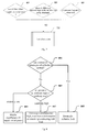
- Fig. 7 is a flowchart of an apparatus for detecting and protecting a telescopic oil cylinder according to an embodiment of the present invention detecting normality.
- Step 702 is performed, namely a normal treatment is carried out.
- the normal treatment includes: normal oil pressure display, normal control on apparatus, etc.
- the opening size of the solenoid valve and/or the displacement of the pump are regulated according to the large-cavity oil pressure in the telescopic oil cylinder, the small-cavity oil pressure in the telescopic oil cylinder and the magnitude of the handle value corresponding to the stretching and contracting motion.
- the smooth operation performance of the system may be improved.
- the opening size of the solenoid valve is quantified in the range of 0-100%
- the magnitude of the handle value corresponding to the stretching and contracting motion is quantified in the range of 0-100%
- the oil pressures in the large cavity and the small cavity is quantified in the range of 0-100%. It should be understood that in order to ensure the fine motion property and speed of the stretching and contracting motion, the handle value, the opening size of the solenoid valve, the pressure values of the large cavity and the small cavity, and the stretching/contracting speed are associated, but not in a general linear relationship.
- the pressure value of the large cavity should be kept in the range of 20-25%, and the opening of the solenoid valve corresponding to the large cavity should be regulated in the range of 0-35%, so as to meet the requirement.
- the pressure value of the large cavity should be kept in the range of 35-45%, and the opening of the solenoid valve corresponding to the large cavity should be regulated in the range of 70-100%, so as to meet the requirement.
- the embodiments described above are exemplary only, and cannot limit the present invention.
- the process of implementing the stretching and contracting motion is illustrated above by taking it as an example that the oil pressure difference between the large cavity and the small cavity is regulated by controlling the opening size of the solenoid valve.
- the controller limits the associated output, so that the speed of stretching and contracting motion is reduced to 15% of the maximum speed, thus helping the system safely and smoothly makes the stretching and contracting motion.
- the ⁇ above may also be the output torque of the engine or the power of the oil pump. Similar description is not repeated here.
- the load of the telescopic oil cylinder is heavier and heavier; in order to ensure enough pressure support, at that time the large-cavity oil pressure in the telescopic oil cylinder has to become higher, and thus the engine has to output a larger torque at that time.
- the motion of stretching with the cylinder being idle is made, since the gravity of booms is taken away, the load will become lighter, and thus the engine no longer has to provide too large a torque at that time. While the power needed by the engine is ensured, the effect of energy-saving and emission-reduction can be achieved by avoiding the 'light load drive' phenomenon.
- one or more set values may be set for the large cavity oil pressure and small cavity oil pressure; for example, two set values are set; during the motion of stretching with a boom, the small-cavity pressure is normal, but the large-cavity pressure gradually increases; if the large-cavity oil pressure is higher than the first set value and there is still no motion, an early warning treatment is provided (for example sound and light alarm); if the large-cavity oil pressure is higher than the second set value (the second set value is greater than the first set value), the solenoid valve is closed to stop the motion of stretching with a boom, so as to prevent the telescopic system from being damaged by overpressure, for example cylinder blow-up.
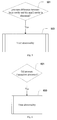
- Figs. 4-6 Shown in Figs. 4-6 is a process of treatment for abnormality.
- the skilled in the art should understand that the sequence of performing the three detecting operations, namely detecting whether the pressures in the telescopic oil cylinder exceeds limit values (401), detecting whether the oil pressure difference between the large cavity and the small cavity is abnormal (501), and detecting whether the fluctuation in oil pressure in the telescopic oil cylinder is abnormal (601), may be determined by the skilled in the art themselves according to the specific circumstances and needs.
- Various abnormal cases are illustrated below respectively in conjunction with the accompanying drawings and the specific embodiments.
- Fig. 4 is a flowchart of an apparatus for detecting and protecting a telescopic oil cylinder according to an embodiment of the present invention when detecting that pressures exceed limit values.
- Step 401 it is detected whether the large-cavity oil pressure and the small-cavity oil pressure in the telescopic cavity exceed their respective limit values, including upper and lower limits.
- limit values including upper and lower limits.
- the skilled in the art can set different limit values.
- the upper limit for the large-cavity oil pressure is 160 bar
- the lower limit for the large-cavity oil pressure is 5 bar
- the upper limit for the small-cavity oil pressure is 240 bar
- the lower limit for the small-cavity oil pressure is 8 bar.
- the above mentioned oil pressure limit values are exemplary only and should not be construed as limiting the present invention.
- Step 403 When it is detected that the oil pressures in the telescopic cavity exceed their respective limit values, Step 403 is performed, namely the abnormality is treated.
- the modes of treating the abnormality include:
- Fig. 5 is a flowchart of an apparatus for detecting and protecting a telescopic oil cylinder according to an embodiment of the present invention when detecting that the oil pressure difference between the large cavity and the small cavity is abnormal; in Step 501, it is detected whether the large-cavity oil pressure difference and the small-cavity oil pressure difference are abnormal.
- the abnormal state of the oil pressure difference between the large cavity and the small cavity varies from crane to crane; for example, the oil pressure difference between the large cavity and the small cavity that is permissible for the cylinder varies from crane to crane; for the same crane, the oil pressure difference between the large cavity and the small cavity varies according to different conditions; for example, during the boom stretching motion and the boom contracting motion, the variation in the required speed results in a variation in the oil pressure difference between the large cavity and the small cavity.
- the abnormal state of the large cavity and the small cavity of the telescopic oil cylinder of the crane under detection may be determined by numerously repeatedly detecting the oil pressure difference between the large cavity and the small cavity that is permissible for the telescopic oil cylinder of the crane, stretching and contracting motion, etc., description of which is not repeated here.
- Step 503 is performed, namely the abnormality is treated.
- the treatment for abnormality includes:
- Fig. 6 is a flowchart of an apparatus for detecting and protecting a telescopic oil cylinder according to an embodiment of the present invention when detecting that the fluctuation in oil pressure is abnormal.
- Step 601 it is detected whether the fluctuation in oil pressure is abnormal.
- the fluctuation in oil pressure being normal means that the fluctuation in oil pressure is in the allowed range of fluctuation in oil pressure
- the fluctuation in oil pressure being abnormal means that the fluctuation in oil pressure is outside the allowed range of fluctuation in oil pressure.
- the range of fluctuation in oil pressure varies according to the crane, and according to different running states of the same crane, for example whether the boom stretches or contracts.
- the range of fluctuation in oil pressure of the telescopic oil cylinder of the crane may be determined by numerously repeatedly testing, description of which is not repeated here.
- Step 603 is performed, namely the abnormality is treated.
- the treatment for abnormality includes:
- the oil pressures in the large cavity and the small cavity should fluctuates in a narrow range (obtained by numerously repeatedly testing); if the range of fluctuation is outside a wide range, the problem may be caused by a sudden failure, in which case if the handle signal does not return to zero, the opening of the solenoid valve is controlled so that it becomes smaller until closed, namely the speed is reduced until the motion is stopped; if the handle signal returns to zero, it indicates that the operator is aware of the failure and artificially stops the motion, the solenoid valve is closed according to the handle signal, and the motion is stopped.
- the wide range is generally 1.5-3 times of the normal narrow range.
- Fig. 8 is a flowchart of an apparatus for detecting and protecting a telescopic oil cylinder according to an embodiment of the present invention determining that a boom pin cannot be pulled out as a failure.
- the cause of such a failure that the boom pin cannot be pulled out may be analyzed by oil pressure detection of the telescopic oil cylinder.
- the oil pressures in the large cavity and the small cavity are detected; if the oil pressure in one of them is lower than the lower limit, in order to prevent non-smooth motion phenomena such as 'abrupt stretching' and 'abrupt contracting' which are caused by too low an oil pressure in one of them, the motion of pulling the boom pin is prohibited, a sound/light alarm treatment is carried out, and the 'under pressure' fault is reported.
- the motion of pulling the boom pin is not made; instead, oil is first supplied to the large cavity until the pressure is not less than the set value, and only then the motion of pulling the boom pin can be made.
- the method and apparatus of the invention may be implemented in many ways.
- the method and apparatus of the invention can be implemented by software, hardware, firmware, or any combination of software, hardware and firmware.
- the above sequence for the steps of the method is only for the purpose of illustration, and the steps of the method of the present invention are not limited to the sequence specifically described above, unless otherwise specifically stated.
- the present invention may also be implemented as a program recorded in a recording medium, which program comprises machine readable instructions for implementing the method according to the present invention. Accordingly, the present invention also covers a recording medium storing a program for executing the method according to the present invention.
Landscapes
- Engineering & Computer Science (AREA)
- Mechanical Engineering (AREA)
- Physics & Mathematics (AREA)
- Fluid Mechanics (AREA)
- General Engineering & Computer Science (AREA)
- Automation & Control Theory (AREA)
- Fluid-Pressure Circuits (AREA)
Applications Claiming Priority (2)
| Application Number | Priority Date | Filing Date | Title |
|---|---|---|---|
| CN201310710689.2A CN103644172B (zh) | 2013-12-20 | 2013-12-20 | 一种起重机伸缩油缸检测及保护装置和方法 |
| PCT/CN2014/087241 WO2015090097A1 (fr) | 2013-12-20 | 2014-09-24 | Appareil et procédé de détection et de protection de cylindre à huile télescopique de grue |
Publications (2)
| Publication Number | Publication Date |
|---|---|
| EP3078622A1 true EP3078622A1 (fr) | 2016-10-12 |
| EP3078622A4 EP3078622A4 (fr) | 2017-08-02 |
Family
ID=50249437
Family Applications (1)
| Application Number | Title | Priority Date | Filing Date |
|---|---|---|---|
| EP14872677.1A Withdrawn EP3078622A4 (fr) | 2013-12-20 | 2014-09-24 | Appareil et procédé de détection et de protection de cylindre à huile télescopique de grue |
Country Status (5)
| Country | Link |
|---|---|
| US (1) | US10196245B2 (fr) |
| EP (1) | EP3078622A4 (fr) |
| CN (1) | CN103644172B (fr) |
| RU (1) | RU2664030C1 (fr) |
| WO (1) | WO2015090097A1 (fr) |
Families Citing this family (16)
| Publication number | Priority date | Publication date | Assignee | Title |
|---|---|---|---|---|
| CN103644172B (zh) * | 2013-12-20 | 2015-12-30 | 徐州重型机械有限公司 | 一种起重机伸缩油缸检测及保护装置和方法 |
| CN103899599B (zh) * | 2014-04-24 | 2016-04-27 | 徐州重型机械有限公司 | 一种即时流量匹配的控制方法、系统及起重机 |
| CN104444859B (zh) * | 2014-12-10 | 2017-01-04 | 徐州重型机械有限公司 | 单缸插销油缸防泄漏控制方法、装置及单缸插销伸缩系统 |
| DE102015102444B4 (de) * | 2015-02-20 | 2017-01-12 | Marco Systemanalyse Und Entwicklung Gmbh | Verfahren und Vorrichtung zur Bestimmung der Schwenkstellung einer Vorpfändkappe |
| CN106256751B (zh) * | 2015-06-17 | 2017-10-27 | 徐工集团工程机械股份有限公司 | 单缸插销式伸缩臂臂销倒扣的控制方法和系统、及起重机 |
| CN109236801B (zh) * | 2018-10-25 | 2020-03-06 | 湖南中联重科智能技术有限公司 | 起重机伸缩油缸油压状态检测方法、装置及起重机 |
| CN109237194B (zh) * | 2018-11-12 | 2021-01-29 | 上海宏波工程咨询管理有限公司 | 管道临时封堵装置和管道临时封堵方法 |
| CN110410384B (zh) * | 2019-09-01 | 2024-03-08 | 宋彦宏 | 一种液压管路的来油测量指示仪及检测方法 |
| CN111943048B (zh) * | 2020-07-30 | 2023-04-11 | 湖南双达机电有限责任公司 | 起重机械的控制方法、控制系统、液压系统及起重机械 |
| CN112177993B (zh) * | 2020-11-04 | 2025-06-17 | 徐州徐工基础工程机械有限公司 | 变夹紧力的推管机自适应控制系统 |
| CN113757440A (zh) * | 2021-08-31 | 2021-12-07 | 新兴铸管股份有限公司 | 一种炼铁放料系统中腭式阀门控制装置 |
| CN114352590A (zh) * | 2022-01-13 | 2022-04-15 | 四川鼎鸿智电装备科技有限公司 | 一种双缸式液压机构以及压力设备 |
| CN115477239B (zh) * | 2022-07-04 | 2023-04-04 | 韶关市起重机厂有限责任公司 | 一种电控实现的起重机顺序伸缩系统 |
| CN119490133B (zh) * | 2024-10-15 | 2025-09-23 | 中联重科股份有限公司 | 伸缩臂伸出控制方法及其液压控制系统、伸缩作业设备 |
| CN119320047B (zh) * | 2024-11-05 | 2025-05-02 | 江苏中矿重型装备有限公司 | 一种轮胎式堆料机用的伸缩臂架及其使用方法 |
| CN119467448A (zh) * | 2024-12-20 | 2025-02-18 | 徐州重型机械有限公司 | 一种无芯管伸缩油缸控制系统及起重机 |
Family Cites Families (21)
| Publication number | Priority date | Publication date | Assignee | Title |
|---|---|---|---|---|
| SU467878A1 (ru) * | 1973-12-12 | 1975-04-25 | Всесоюзный Научно-Исследовательский Институт По Монтажным И Специальным Строительным Работам | Телескопическа стрелка грузоподъемного крана |
| US4185426A (en) * | 1978-01-30 | 1980-01-29 | A-T-O Inc. | Extension/elevation intra-action device for aerial lift apparatus |
| SU800105A1 (ru) * | 1978-12-11 | 1981-01-30 | Всесоюзный Научно-Исследовательскийинститут Строительного И Дорож-Ного Машиностроения | Гидропривод механизма изменени длиНы СТРЕлы САМОХОдНОгО KPAHA |
| GB9503854D0 (en) * | 1995-02-25 | 1995-04-19 | Ultra Hydraulics Ltd | Electrohydraulic proportional control valve assemblies |
| JPH09216786A (ja) * | 1996-02-15 | 1997-08-19 | Kobe Steel Ltd | 油圧クレーンのブーム伸縮停止保持装置 |
| US6647718B2 (en) * | 2001-10-04 | 2003-11-18 | Husco International, Inc. | Electronically controlled hydraulic system for lowering a boom in an emergency |
| US6662705B2 (en) * | 2001-12-10 | 2003-12-16 | Caterpillar Inc | Electro-hydraulic valve control system and method |
| JP4122903B2 (ja) * | 2002-08-30 | 2008-07-23 | コベルコクレーン株式会社 | クレーン |
| DE10340504B4 (de) * | 2003-09-03 | 2006-08-24 | Sauer-Danfoss Aps | Ventilanordnung zur Steuerung eines Hydraulikantriebs |
| DE10344480B3 (de) * | 2003-09-24 | 2005-06-16 | Sauer-Danfoss Aps | Hydraulische Ventilanordnung |
| GB0416336D0 (en) * | 2004-07-22 | 2004-08-25 | Bamford Excavators Ltd | Method of operating a machine |
| JP4457299B2 (ja) * | 2004-08-19 | 2010-04-28 | Smc株式会社 | エアシリンダの圧力制御方法及び装置 |
| US7614336B2 (en) * | 2005-09-30 | 2009-11-10 | Caterpillar Inc. | Hydraulic system having augmented pressure compensation |
| GB2437615B (en) * | 2006-04-04 | 2011-04-13 | Husco Int Inc | Fluid metering mode transitioning technique for a hydraulic control system |
| CN201154878Y (zh) * | 2007-11-30 | 2008-11-26 | 三一重工股份有限公司 | 单伸缩油缸多节臂伸缩控制装置 |
| CN101446305B (zh) * | 2008-10-16 | 2011-03-16 | 太原理工大学 | 一种液压缸并行控制回路系统 |
| US8631651B2 (en) * | 2009-01-21 | 2014-01-21 | Manitowoc Crane Companies, Llc | Hydraulic system thermal contraction compensation apparatus and method |
| CN202829338U (zh) * | 2012-09-07 | 2013-03-27 | 三一重工股份有限公司 | 单缸插销式伸缩臂及其臂位检测系统、起重机 |
| CN103244472B (zh) * | 2013-05-08 | 2016-03-16 | 中国重型机械研究院股份公司 | 一种液压式平衡结晶器重力负载的伺服液压缸阀系统 |
| CN103307060B (zh) * | 2013-06-18 | 2016-02-03 | 南京埃斯顿自动化股份有限公司 | 直驱式伺服泵控电液混合驱动的液压缸控制系统及控制方法 |
| CN103644172B (zh) * | 2013-12-20 | 2015-12-30 | 徐州重型机械有限公司 | 一种起重机伸缩油缸检测及保护装置和方法 |
-
2013
- 2013-12-20 CN CN201310710689.2A patent/CN103644172B/zh active Active
-
2014
- 2014-09-24 EP EP14872677.1A patent/EP3078622A4/fr not_active Withdrawn
- 2014-09-24 WO PCT/CN2014/087241 patent/WO2015090097A1/fr not_active Ceased
- 2014-09-24 RU RU2016129160A patent/RU2664030C1/ru not_active IP Right Cessation
-
2016
- 2016-06-17 US US15/186,403 patent/US10196245B2/en active Active
Also Published As
| Publication number | Publication date |
|---|---|
| EP3078622A4 (fr) | 2017-08-02 |
| US10196245B2 (en) | 2019-02-05 |
| RU2664030C1 (ru) | 2018-08-14 |
| WO2015090097A1 (fr) | 2015-06-25 |
| CN103644172A (zh) | 2014-03-19 |
| US20160289050A1 (en) | 2016-10-06 |
| RU2016129160A (ru) | 2018-01-25 |
| CN103644172B (zh) | 2015-12-30 |
Similar Documents
| Publication | Publication Date | Title |
|---|---|---|
| US10196245B2 (en) | Apparatus and method for detecting and protecting telescopic oil cylinder of crane | |
| JP6112085B2 (ja) | 油圧圧下サーボ弁の故障診断方法および装置 | |
| Athanasatos et al. | Proactive fault finding in a 4/3-way direction control valve of a high pressure hydraulic system using the bond graph method with digital simulation | |
| CN102849643B (zh) | 一种液压卷扬机构故障判断方法及系统 | |
| CN102701089B (zh) | 工程机械及其吊臂的落臂安全控制系统 | |
| CN110240067B (zh) | 一种岸桥倾转-挂仓一体化电液控制系统及其控制方法 | |
| CN105984809A (zh) | 液压系统及起重机 | |
| CN106644427A (zh) | 能进行非线性补偿的自动化控制的阀门电动装置寿命的试验系统 | |
| Xu et al. | Safety brake performance evaluation and optimization of hydraulic lifting systems in case of overspeed dropping | |
| DE102016213236A1 (de) | Elektronische ventilbetätigungsteuerung und druckkompensierung | |
| CN102849642A (zh) | 一种液压卷扬机构控制方法及系统 | |
| EP3428112A1 (fr) | Palan, en particulier une grue mobile ou une pelleteuse à câbles, doté d'un dispositif de surveillance du processus de dressage et d'enlèvement d'un système de rampe et procédé correspondant | |
| CN205404094U (zh) | 新型等速驱动轴扭转疲劳试验台 | |
| CN113124019B (zh) | 数字逻辑阀阵列液压伺服控制系统、控制方法与故障诊断方法 | |
| DE102012011726B4 (de) | Verfahren zum Betreiben eines Krans mit Überwachungseinheit sowie Kran | |
| JP2006290561A (ja) | クレーン作業制御装置 | |
| CN103629190B (zh) | 一种平衡阀不匹配导致负载抖动的测量方法及装置 | |
| KR101451110B1 (ko) | 건설기계용 유압장비 진단유닛 | |
| CN203906449U (zh) | 一种气缸泄露监控系统 | |
| CN203639917U (zh) | 一种用于控制立柱的电手柄的自动检测及控制装置 | |
| CN220185509U (zh) | 一种伸缩缸装置 | |
| CN205047562U (zh) | 一种电磁开关阀的逻辑油路控制系统 | |
| BR112014016103B1 (pt) | Sistema de prevenção de sobrepressâo para uma bomba hidráulica eletrônica em um ststema hidráulico | |
| CN104132852A (zh) | 一种同时域多频段液压试验系统及其控制方法 | |
| CN116425067A (zh) | 一种揽风机构及其液压控制系统 |
Legal Events
| Date | Code | Title | Description |
|---|---|---|---|
| PUAI | Public reference made under article 153(3) epc to a published international application that has entered the european phase |
Free format text: ORIGINAL CODE: 0009012 |
|
| 17P | Request for examination filed |
Effective date: 20160707 |
|
| AK | Designated contracting states |
Kind code of ref document: A1 Designated state(s): AL AT BE BG CH CY CZ DE DK EE ES FI FR GB GR HR HU IE IS IT LI LT LU LV MC MK MT NL NO PL PT RO RS SE SI SK SM TR |
|
| AX | Request for extension of the european patent |
Extension state: BA ME |
|
| DAX | Request for extension of the european patent (deleted) | ||
| A4 | Supplementary search report drawn up and despatched |
Effective date: 20170703 |
|
| RIC1 | Information provided on ipc code assigned before grant |
Ipc: B66C 23/70 20060101AFI20170627BHEP |
|
| STAA | Information on the status of an ep patent application or granted ep patent |
Free format text: STATUS: THE APPLICATION HAS BEEN WITHDRAWN |
|
| 18W | Application withdrawn |
Effective date: 20200930 |