EP3078629A1 - Dosage de distribution hygiénique avec modification d'un angle d'inclinaison (réservoir de concentré et procédé de distribution) - Google Patents
Dosage de distribution hygiénique avec modification d'un angle d'inclinaison (réservoir de concentré et procédé de distribution) Download PDFInfo
- Publication number
- EP3078629A1 EP3078629A1 EP15162863.3A EP15162863A EP3078629A1 EP 3078629 A1 EP3078629 A1 EP 3078629A1 EP 15162863 A EP15162863 A EP 15162863A EP 3078629 A1 EP3078629 A1 EP 3078629A1
- Authority
- EP
- European Patent Office
- Prior art keywords
- container
- pivot point
- storage system
- lifting mechanism
- pivoting
- Prior art date
- Legal status (The legal status is an assumption and is not a legal conclusion. Google has not performed a legal analysis and makes no representation as to the accuracy of the status listed.)
- Withdrawn
Links
Images

Classifications
-
- B—PERFORMING OPERATIONS; TRANSPORTING
- B67—OPENING, CLOSING OR CLEANING BOTTLES, JARS OR SIMILAR CONTAINERS; LIQUID HANDLING
- B67D—DISPENSING, DELIVERING OR TRANSFERRING LIQUIDS, NOT OTHERWISE PROVIDED FOR
- B67D3/00—Apparatus or devices for controlling flow of liquids under gravity from storage containers for dispensing purposes
- B67D3/0051—Apparatus or devices for controlling flow of liquids under gravity from storage containers for dispensing purposes dispensing by tilting
-
- B—PERFORMING OPERATIONS; TRANSPORTING
- B67—OPENING, CLOSING OR CLEANING BOTTLES, JARS OR SIMILAR CONTAINERS; LIQUID HANDLING
- B67D—DISPENSING, DELIVERING OR TRANSFERRING LIQUIDS, NOT OTHERWISE PROVIDED FOR
- B67D3/00—Apparatus or devices for controlling flow of liquids under gravity from storage containers for dispensing purposes
- B67D3/0058—Details
- B67D3/008—Supports
- B67D3/0083—Supports for the liquid container
Definitions
- This disclosure (and claims) relate to dispensing a concentrate store with a lift mechanism that allows the use of conventional beverage containers (as beverage concentrate containers), but can also accommodate special packages having an overhead "dispensing snout" (a openable closing side or closing edge).
- Usual and current common beverage dispensers are open dispensers or premix dispensers in which a beverage is in a container and this container is arranged above a cooling unit on a cooling plate.
- the beverage can be agitated by means of a stirrer to mix it evenly (if fruit fibers are present) or at least to cool evenly, so that the user can remove and take his drink portion taken from the output at a uniform temperature.
- the beverage containers there are flexible bags, see. EP 2 181960 B1 (Wolfgang Jobmann ) or already filled with drinkable liquid containers that are used in the beverage dispenser.
- This invention deals with a beverage concentrate storage and dispensing system contained in a container intended to dispense its contents accurately. Particular attention is paid to hygiene.
- a dispensed concentrate dose is mixed with water to form a beverage.
- the invention sees their technical problem, achieving perfect hygiene in conjunction with a very precisely metered output.
- the solution proposed is a storage and dosing system with a base that carries a container (or not more than partially receives).
- the container is adapted and suitable to receive the concentrate as a liquid.
- the storage and metering system is adapted and suitable to carry the container with the concentrate therein or just not more than partially absorb (claim 1).
- the container is or will be stored at insertion at an off-center pivot point. This is higher than the lower portion of the container. To this pivot point of the container from the base in an upward direction is movable, which is implemented on the or force of the pivot point in an upwardly directed pivoting movement.
- the pivot point can be viewed as a stationary bearing (or a storage line) at the top of the pedestal and refers to the container (with the concentrate as a liquid).
- At least one lifting mechanism with a bow-shaped element is provided. This can lift the container pivotally, wherein the sheet movement is controlled by the lifting mechanism and the pivot point (claim 1, claim 18).
- Said arcuate lifting mechanism consists of two basic elements and may engage or be associated with both the one side (the vertical flat side) and the opposite side of the container (claim 6, claim 16).
- Attaching a Nutenkette that is bent, z. B. in the manner of a quarter circle, is an element of the arcuate lifting mechanism (claim 2).
- This sequence of Nuten consultancyen is associated with a teeth element as a second element, which engages with its teeth in the sequence of grooves of Nutenkette and the pivoting movement by rotating the teeth element allows (claim 3).
- This tooth element is arranged immovably on the base, preferably in an upper region and engages there in the arcuate groove chain. It is rotatable and assigns in a particular embodiment of a vertical strut, which belongs to the base as a component.
- the pedestal itself accommodates the container, has a front wall, a bottom floor and the at least one vertical strut, which rotatably supports the rotatable or rotatable tooth element on an upper portion.
- the other vertical flat side of the container is also associated with such a rotatable or rotatable tooth element, respectively the arcuate groove chain arranged there on this vertical wall of the container.
- This is parallel to the other Nutenkette and in the same altitude, so that a synchronous running with uniformly rotating teeth elements is possible (claim 4).
- teeth of the toothed element engage in grooves of the groove chain and upon rotation of the toothed element, the container pivots, supported on the linear pivoting point, so that the concentrate can be dispensed precisely metered as liquid at a pouring spout or at an open edge of the beverage container (claim 7).
- an additional opening may be provided at another point of the container, the pressure equalization after opening the spout and opening the second opening on the container allows (claim 7).
- a container may be used, which is formed in the manner of a "Tetra-Pak” packaging, with two triangular tabs on both upper short edges of the cuboid (often called by Tetra Pak itself "brick beverage packaging", although the term as appellative name input into the linguistic usage took, based on Tetra Brik, the cuboid cardboard packaging). Both tabs may even be the same design, one used in the open state as a spout, the second used in the open state for pressure equalization.
- this Tetra Brik-like container can also be much larger and take many liters of concentrate, not just one liter, but quite 2 I, 5 I, or 10 I, which corresponds to a corresponding dimensioning of the container.
- the container for the concentrate is due to the existing two walls which carry the arcuate groove chains, provided with a certain rigidity, so that provided in the container flexible inner wall (claim 5) is held by a stiffer or rigid outer wall to the Nutenketten a sufficient To give stability in their position and fixation on these walls (claim 5).
- the cutting of the inner film as a flexible inner wall is associated with the cutting of an edge or a bent-away, substantially triangular edge element, which forms the discharge spout.
- the pressure equalization port may also be elsewhere, but may also be the opposite spout, which serves as an alternative to ventilation.
- the result is a storage and metering system that emits a uniform amount of liquid as a concentrate at a given opening time.
- the liquid does not flow out from a lower portion of the container, but it flows from an upper edge portion which extends over the pivot bearing and thus has a sufficient distance from the ground level of the container to a glass or a cup between the bottom and output to to be able to hold or hold.
- Both teeth elements are rigidly coupled to each other via a shaft, so that the motor can be used to pivot the container upwards, for example by means of a motor drive. B. alone time-controlled. If only one lifting mechanism is used, only one tooth element needs to be actuated, which may also be caused by a lever (Claim 9).
- the rotatable tooth element may be coupled to the lever such that there is a freewheel in a pivoting direction and in the second pivoting direction an attack of the lever on the tooth element takes place to act entizid or rotating, thus causing the upward pivoting movement of the beverage container ,
- a backstop may be provided (claim 8).
- a mechanical backstop which has a certain angle screening or a certain dead time
- an electrical lock can be made so that the engine keeps a rotational position by current permanently and thus no screening of the pivotal positions is given, but via the transmission, the may well be a self-locking gear, the rotational position of the container can be maintained without deviating even one millimeter from the achieved pivotal position and thus achieved tilt height of the container.
- a marginal vomschwenkiolo occurs when stopping the rotation about the motor, so that no liquid is present at the output directly, but very slightly before such an output has its highest pivot position, for example not more than 0.5 mm to 1 mm ,
- the groove chain may preferably be made of polycarbonate, or of a strongly consolidated cardboard (claim 13). It is understood that the tooth elements of the rotatable tooth element correspond in their pitch of the groove pitch of the arcuate groove chain. If more than one arcuate lifting mechanism is used, for example two (claim 14), these are associated with the two vertical flat sides of the container and the statements made above apply to these two arcuate lifting mechanisms (claim 14).
- the tooth element may also be made of polycarbonate, or be formed of metal (claim 15).
- a mounting plate can be arranged on the arcuate groove chain, which allows sticking over a sufficiently large area in the manner of a T-shape, which in addition arcuately flat and not interrupted by grooves and not serrated or wavy one-sided limited.
- the method for the metered dispensing or pouring of the viscous liquid is one with a very precise output quantity of a location which is higher than at least half of the viscous liquid in its filling level, or half of the filling level (claim 18).
- the viscous liquid is preferably a fruit juice concentrate (claim 19).
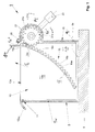
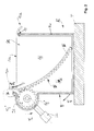
- FIGS. 1 and 2 show two opposite side views of a container 10 which is inserted into a support frame 5, wherein the view of a relatively stiff side wall 10b in FIG. 1 and the opposite side wall 10c in FIG FIG. 2 you can see.
- FIG. 1 On the left to see the spout 12a, which is in an open state and located above a pivot joint 11.
- the supervision of the FIG. 4 illustrates the spout 12a, which forms an edge or corner, which may be bent away from the body of the cuboid 10 forward, for example, as a triangular shape, arises. She is cut open and in the FIG. 1 is symbolically the outflow path to see, which would not be seen in a view of the side wall 10b, ausfliest and dispensed metered.
- the pressure equalization via a second spout which here corresponds to the spout 12 a left, but is bent up, provided as pressure equalization 12 b, even in the open state, so that air can flow, while concentrate, which is not shown here, but visible would be presented within the container 10 in an internal flexible partition 10a.
- the support frame 5 consists of several elements that from the synopsis of FIGS. 1 to 4 be clear.
- the front wall 5w which may be a flat wall.
- the support frame on another wall 5b, which serves as a floor.
- two upright struts 5i and 5j at which at the upper end or better, in an upper section, a respective gear is arranged as an example of a toothed element 21 which is rotatable or capable of rotating.
- the provided as a vertical strut 5i and vertical opposite strut 5j support arm belongs to the support frame and is to be called altogether as a base 5, which consists of front wall, bottom wall and two spaced vertical struts back.
- the respective gear 21 can engage the arcuate grooved rail 15, which has a plurality of grooves 15a, 15b, ... to 15x and 15z. These grooves have with their formed intermediate teeth to the gear, which engages only in the upper portion of the groove rod 15 in these grooves, in the example in the groove portion 15z and tooth portion 21z, the latter one tooth of the plurality of teeth 21a, 21b, ..., 21x to 21z of the rotatable toothed element 21 is. In the same way as for the left teeth element of FIG. 3 applies, it is also for the right teeth member 21 of FIG. 3 apply.
- Socket 5 frame is so two-sided (left and right) open and also largely open on the back. It is therefore to be called a pedestal because it carries the container 10, which receives the mixable concentrate and releases the pouring opening 12a.
- the base 5 stands on a support piece T, which can be regarded as a table or counter.
- the pivot point 11 is, as can be seen from the figures, not centrally located relative to the container 10. It is disposed opposite to the upper portion of the lifting mechanism, which is left of the upper portion of the rack 15 and the teeth member 21 and, if two such arcuate lifting mechanisms are provided, also right in FIG. 2 consists.
- the base 5 has a preferred embodiment with respect to the struts 5i and 5j, in which the struts have a lower support portion and an upwardly extended arc portion 5i 'and 5j'. For reasons of safety, this surrounds the respective tooth element 21, which can rotate under this protection.
- a reverse rotation lock (functionally considered) which here consists of a lever 26 inserted in one of the grooves between two teeth of the tooth element 21 engages and through an opening of the arc section 5i 'engages.
- the reverse rotation lock 26 dissolves due to the width of the passage opening through the upper end of the arc section 5i 'and passes the next tooth. Thereafter, when the gear 21 is no longer moved by the lever 22 in the clockwise direction, it engages again and holds the gear on the rotational position, as shown. In this case, has shown by the engagement of the tooth 21z in the groove 15z, as shown, an upward movement of the arcuate groove rod 15, whereby the container 10 has been raised a bit.
- FIG. 3 The lifting of the container takes place in the form of an arc around the bearing 11 around, as in the lower right corner of the FIG. 1 is indicated by phi 1 '.
- This corner can move upwards because the back wall is recessed and only the left and right vertical struts 5i and 5j stand.
- FIG. 3 This is special FIG. 3 can be seen, in which the rear wall 10d of the container with the drink can be seen.
- the main swing direction phi 1 is off FIG. 1 to see, as well as FIG. 2 ,
- This pivoting direction is along a parallel to the curved groove rod 15 (also referred to as rack above, because it consists of grooves 15a, 15b and each intermediate of a tooth between two grooves).
- the drive of the teeth elements 21 can take place via a lever 22, which has different effects on the tooth element 21 in both possible pivoting directions.
- Freewheel is provided in a pivoting direction, so that the lever can be pivoted upwards without the gear 21 moving.
- an unillustrated mechanism engages the shaft 22 so that downward depression of the lever 22 results in a clockwise position change FIG. 1 leads, the reverse rotation lock triggers 26 and the container 10 acts far pivoted upwardly a piece of which the pivoting direction phi 1 leads to a greater inclination.
- the fluid is dispensed in a very metered manner at the discharge nozzle 12a, and by the backstop 26 an achieved pivoting position can be stabilized and held.
- the fluid may then be re-dispensed on a next rotary stroke movement for the lever 22, by incrementally increasing with an incremental increase in the rotational position angle phi 2 for the tooth element 21 and the rotational position phi 1 for the container 10.
- the strut 5j disposed on the other side of the base 5 also has an arcuate portion 5j 'protecting the gear 21, respectively the user in front of the gear 21, and an upper end 5j "on which the reverse rotation lock 26 is arranged.
- the shaft 22 can be seen to couple both teeth elements 21 in a rotationally rigid manner, so that a uniform and uniform incremental upward movement with incremental angular pivoting positions is provided on both sides and along both groove chains 15.
- This shaft 22 can be driven by an electric motor, not shown, which can be coupled via a transmission, so that an even finer tuning is possible.
- the electric motor can have a holding current (bias), which holds the motor in a rotational position, in order to keep the pivot position ⁇ 1 of the container.
- the engine may also have a self-locking gear, so that this gear ensures the pivot position. The larger the loads become, the larger the size of containers, the more finely graded the incremental delivery should be and the more accurate a pivotal position should be maintained.
- the groove chain as a groove rod 15 may be made of polycarbonate and is preferably adhered to the side wall 10b.
- the opposite side wall 10c may have an additional groove rod 15 also glued polycarbonate, if two arcuate lifting mechanisms are provided.
- the system can also work with such a mechanism of arcuate rack 15 and teeth member 21 in smaller containers 10.
- polycarbonate rack alternatives to the polycarbonate rack are those made of other plastic or solidified cardboard (or solidified pulp).
- the driving or pivoting tooth element as gear-like element may be formed of plastic or metal.
- An initial pivoted position in order to reach the base level for the metered dispensing of the inner concentrate in the container 10, is adjustable, ⁇ 10 through a quiescent current I 10 of the electric motor drive at either the lever 22, by means of clamping screws or a preset with a base pivot position the wave 22.
- This Base current simultaneously reaches the bias, ie reaching the first pivot position ⁇ 10 and holding at this position.
- tooth pitch of teeth element 21 and groove chain 15 is adapted to each other, with the largest possible gear is to choose when a ratio near 1 is to be achieved and the smallest possible gear is to be selected when a lower ratio is to be achieved , That is, several rotations or a larger change in the rotational position of the gear 21 at a lower pivoting ⁇ 1 of the container 10th
- a possible connection of the groove chains 15 with the respective side wall 10b or 10c takes place via an adhesive suitable for polycarbonate.
- the groove chain 15 may also have a T-shaped flat bottom, which allows the adhesive bond better and more reliable, especially with regard to the edges and the edge contour uniform.
- the pivot point 11 is the instantaneous pivot point of the container 10, with a lever arm r reaching from the pivot point 11 to the tooth 21z in the groove 15z of the arcuate groove chain 15.
- the groove chain 15 is adapted in shape so that the pivot point 11 is the geometric center of the arc, which has the Nutenkette 15.
Landscapes
- Engineering & Computer Science (AREA)
- Mechanical Engineering (AREA)
- Devices For Dispensing Beverages (AREA)
Priority Applications (1)
| Application Number | Priority Date | Filing Date | Title |
|---|---|---|---|
| EP15162863.3A EP3078629A1 (fr) | 2015-04-08 | 2015-04-08 | Dosage de distribution hygiénique avec modification d'un angle d'inclinaison (réservoir de concentré et procédé de distribution) |
Applications Claiming Priority (1)
| Application Number | Priority Date | Filing Date | Title |
|---|---|---|---|
| EP15162863.3A EP3078629A1 (fr) | 2015-04-08 | 2015-04-08 | Dosage de distribution hygiénique avec modification d'un angle d'inclinaison (réservoir de concentré et procédé de distribution) |
Publications (1)
| Publication Number | Publication Date |
|---|---|
| EP3078629A1 true EP3078629A1 (fr) | 2016-10-12 |
Family
ID=52987933
Family Applications (1)
| Application Number | Title | Priority Date | Filing Date |
|---|---|---|---|
| EP15162863.3A Withdrawn EP3078629A1 (fr) | 2015-04-08 | 2015-04-08 | Dosage de distribution hygiénique avec modification d'un angle d'inclinaison (réservoir de concentré et procédé de distribution) |
Country Status (1)
| Country | Link |
|---|---|
| EP (1) | EP3078629A1 (fr) |
Citations (5)
| Publication number | Priority date | Publication date | Assignee | Title |
|---|---|---|---|---|
| DE215235C (fr) * | ||||
| GB2272878A (en) * | 1992-11-24 | 1994-06-01 | Drane Sarah Pauline | Apparatus for tilting a container |
| GB2292727A (en) * | 1994-09-03 | 1996-03-06 | Graham Woolley | Tilting Apparatus |
| DE29907967U1 (de) * | 1999-05-05 | 1999-08-12 | Protechna Sa | Vorrichtung zum Entleeren von Transport- und Lagerbehältern für Flüssigkeiten |
| EP2181960B1 (fr) | 2008-10-30 | 2012-09-12 | Wolfgang Jobmann GmbH | Distributeur de prémélanges avec sachet pour boissons et à haute capacité de refroidissement |
-
2015
- 2015-04-08 EP EP15162863.3A patent/EP3078629A1/fr not_active Withdrawn
Patent Citations (5)
| Publication number | Priority date | Publication date | Assignee | Title |
|---|---|---|---|---|
| DE215235C (fr) * | ||||
| GB2272878A (en) * | 1992-11-24 | 1994-06-01 | Drane Sarah Pauline | Apparatus for tilting a container |
| GB2292727A (en) * | 1994-09-03 | 1996-03-06 | Graham Woolley | Tilting Apparatus |
| DE29907967U1 (de) * | 1999-05-05 | 1999-08-12 | Protechna Sa | Vorrichtung zum Entleeren von Transport- und Lagerbehältern für Flüssigkeiten |
| EP2181960B1 (fr) | 2008-10-30 | 2012-09-12 | Wolfgang Jobmann GmbH | Distributeur de prémélanges avec sachet pour boissons et à haute capacité de refroidissement |
Similar Documents
| Publication | Publication Date | Title |
|---|---|---|
| DE10309589B4 (de) | Packungsspender | |
| DE69905234T2 (de) | Nachfüllkartusche für eine Getränke-Abgabevorrichtung und an solche Kartuschen angepasste Vorrichtung | |
| DE69006451T2 (de) | Druckknopf für Misch- und Dosiervorrichtung. | |
| DE4429662B4 (de) | Haltevorrichtung | |
| DE202011109919U1 (de) | Kaffeebohnenverpackungspatrone und diese enthaltendes Kaffeegetränksystem | |
| DE202011106496U1 (de) | Lebensmittelspender | |
| EP3801150B1 (fr) | Unité pour un dispositif à café | |
| DE3921971C2 (fr) | ||
| EP1957393B1 (fr) | Appareil distributeur pour produits coulants ou en vrac | |
| DE1959174B2 (de) | Vorrichtung zum aufstapeln von kartonzuschnitten | |
| DE69907009T2 (de) | Abgabevorrichtung für abgabe von gefrorenen süssspeisen aus vorgefüllten behältern, und ein abgabesytem mit einer abgabevorrichtung und mehreren behälter | |
| EP1108656A2 (fr) | Récipient pour plusieurs composants pour stocker et distribuer des produits liquides ou pâteux | |
| EP3078629A1 (fr) | Dosage de distribution hygiénique avec modification d'un angle d'inclinaison (réservoir de concentré et procédé de distribution) | |
| CH435556A (de) | Tropfeinsatz für einen Behälter | |
| DE102022128540B4 (de) | Verschließvorrichtung für einen Mahlgutbehälter, Mahlgutbehälter, und Kaffeemaschine mit einem solchen Mahlgutbehälter | |
| DE3903933A1 (de) | Verschliessmaschine fuer flaschen | |
| WO2007113192A1 (fr) | sac à boisson doté d'une poche mobile pour un distributeur servant de système de prélèvement de boissons et procédé d'utilisation associé | |
| DE602005004780T2 (de) | Kapselladevorrichtung zur bestückung eines kapselausgabeautomaten | |
| DE202021105418U1 (de) | Abgabevorrichtung, Abgabesystem und Möbelstück zur dosierten Abgabe einer Flüssigkeit aus einem Flüssigkeitsbeutel | |
| DE4434031C2 (de) | Dosiergefäßanordnung | |
| DE2302848A1 (de) | Vorrichtung zum portionieren von lebensmitteln | |
| DE69704858T2 (de) | Flüssigkeitsabgabevorrichtung | |
| EP2562727B1 (fr) | Dispositif de commande automatique pour marchandises | |
| DE3107000A1 (de) | "warenausgabevorrichtung fuer automaten" | |
| DE102009059340B4 (de) | Vorrichtung zur Aufnahme eines Schlauches, insbesondere eines Schlauches aus einem Bag-in-Box-System |
Legal Events
| Date | Code | Title | Description |
|---|---|---|---|
| PUAI | Public reference made under article 153(3) epc to a published international application that has entered the european phase |
Free format text: ORIGINAL CODE: 0009012 |
|
| AK | Designated contracting states |
Kind code of ref document: A1 Designated state(s): AL AT BE BG CH CY CZ DE DK EE ES FI FR GB GR HR HU IE IS IT LI LT LU LV MC MK MT NL NO PL PT RO RS SE SI SK SM TR |
|
| AX | Request for extension of the european patent |
Extension state: BA ME |
|
| 17P | Request for examination filed |
Effective date: 20161014 |
|
| RBV | Designated contracting states (corrected) |
Designated state(s): AL AT BE BG CH CY CZ DE DK EE ES FI FR GB GR HR HU IE IS IT LI LT LU LV MC MK MT NL NO PL PT RO RS SE SI SK SM TR |
|
| 17Q | First examination report despatched |
Effective date: 20170214 |
|
| GRAP | Despatch of communication of intention to grant a patent |
Free format text: ORIGINAL CODE: EPIDOSNIGR1 |
|
| INTG | Intention to grant announced |
Effective date: 20171106 |
|
| STAA | Information on the status of an ep patent application or granted ep patent |
Free format text: STATUS: THE APPLICATION IS DEEMED TO BE WITHDRAWN |
|
| 18D | Application deemed to be withdrawn |
Effective date: 20180317 |