EP3078638B1 - Cartouche de filtre a eau et reservoir a eau - Google Patents
Cartouche de filtre a eau et reservoir a eau Download PDFInfo
- Publication number
- EP3078638B1 EP3078638B1 EP16159547.5A EP16159547A EP3078638B1 EP 3078638 B1 EP3078638 B1 EP 3078638B1 EP 16159547 A EP16159547 A EP 16159547A EP 3078638 B1 EP3078638 B1 EP 3078638B1
- Authority
- EP
- European Patent Office
- Prior art keywords
- water
- magnetic field
- tank
- filter cartridge
- filter
- Prior art date
- Legal status (The legal status is an assumption and is not a legal conclusion. Google has not performed a legal analysis and makes no representation as to the accuracy of the status listed.)
- Active
Links
Images



Classifications
-
- C—CHEMISTRY; METALLURGY
- C02—TREATMENT OF WATER, WASTE WATER, SEWAGE, OR SLUDGE
- C02F—TREATMENT OF WATER, WASTE WATER, SEWAGE, OR SLUDGE
- C02F1/00—Treatment of water, waste water, or sewage
- C02F1/001—Processes for the treatment of water whereby the filtration technique is of importance
- C02F1/003—Processes for the treatment of water whereby the filtration technique is of importance using household-type filters for producing potable water, e.g. pitchers, bottles, faucet mounted devices
-
- C—CHEMISTRY; METALLURGY
- C02—TREATMENT OF WATER, WASTE WATER, SEWAGE, OR SLUDGE
- C02F—TREATMENT OF WATER, WASTE WATER, SEWAGE, OR SLUDGE
- C02F2201/00—Apparatus for treatment of water, waste water or sewage
- C02F2201/002—Construction details of the apparatus
- C02F2201/006—Cartridges
-
- C—CHEMISTRY; METALLURGY
- C02—TREATMENT OF WATER, WASTE WATER, SEWAGE, OR SLUDGE
- C02F—TREATMENT OF WATER, WASTE WATER, SEWAGE, OR SLUDGE
- C02F2209/00—Controlling or monitoring parameters in water treatment
- C02F2209/005—Processes using a programmable logic controller [PLC]
- C02F2209/008—Processes using a programmable logic controller [PLC] comprising telecommunication features, e.g. modems or antennas
-
- C—CHEMISTRY; METALLURGY
- C02—TREATMENT OF WATER, WASTE WATER, SEWAGE, OR SLUDGE
- C02F—TREATMENT OF WATER, WASTE WATER, SEWAGE, OR SLUDGE
- C02F2209/00—Controlling or monitoring parameters in water treatment
- C02F2209/44—Time
- C02F2209/445—Filter life
-
- C—CHEMISTRY; METALLURGY
- C02—TREATMENT OF WATER, WASTE WATER, SEWAGE, OR SLUDGE
- C02F—TREATMENT OF WATER, WASTE WATER, SEWAGE, OR SLUDGE
- C02F2307/00—Location of water treatment or water treatment device
- C02F2307/04—Location of water treatment or water treatment device as part of a pitcher or jug
Definitions
- the invention relates to a water filter cartridge, a water tank and a water-conducting device according to the preambles of claims 1, 9 and 13.
- water filter cartridges are increasingly being used to treat the water before it is actually used.
- Such filter cartridges are designed to be inserted into the water tank and for this purpose are provided with a connection element for connecting a filter drain line to a tank-side connection element.
- the filter housing is provided with permanently open inlet openings for the entry of water from the environment, i.e. from the water tank, so that the water tank can be emptied via the filter cartridge. The water is sucked out via the filter cartridge by a suction pump on the household appliance.
- the state of the art already recognizes that a frequency detuning can occur when electromagnetic waves are transmitted through water. Therefore, in this case, the state of the art provides for a targeted detuning between the communication element on the filter cartridge side and the external communication element arranged on the side of the household appliance during manufacture or when setting the transmission and/or reception frequencies in order to compensate for such a frequency detuning.
- the EN 10 2014 117 725 A1 , EN 10 2006 029 105 A1 and the EN 10 2014 117 720 A1 disclose a beverage machine and a water storage tank that can be connected thereto or a water filter cartridge for insertion into such a water storage tank, each of which communicates with antennas by means of electronic communication elements.
- the object of the present invention is to improve the communication between such electronic communication elements.
- a water filter cartridge for use in a water storage tank of a water-conducting device comprises a filter housing, a filter-side tank connection element and an electronic communication element with antenna as well as at least one magnetic field conducting element.
- such a magnetic field guide element can have magnetic Materials with a permeability number that is significantly greater than 1 ( ⁇ r » 1).
- ⁇ r » 1 a magnetic field conducting element designed in this way.
- the significantly higher conductivity in the magnetic field conducting element compared to its surroundings, such as air and/or plastic, from which filter housings and their mechanical components are usually made, causes a concentration or bundling of magnetic field lines in the interior and/or in the vicinity of such a magnetic field conducting element.
- the magnetic field guide element By arranging and/or aligning a magnetic field guide element in relation to an antenna of an electronic communication element, a significant portion of an occurring magnetic field can be directed in its direction in a targeted manner. It is particularly advantageous if the magnetic field guide element is arranged in an area between two antennas, e.g. between an antenna of a transmitting electronic communication element and an antenna of an electronic communication element operated in receive mode. In one possible embodiment, the magnetic field guide element can therefore be arranged in an area of the water filter cartridge that is located between the antenna of the filter-side electronic communication element and a point on the water filter cartridge, which point, when the water filter cartridge is inserted, points in the direction of the antenna of a complementary tank-side communication element and/or device-side communication element provided for communication with the filter-side communication element.
- the concentration or bundling of the magnetic field also results in local amplification effects for the magnetic field.
- the amplification effect of the magnetic field guide element based on the field line concentration This can advantageously result in a massive increase in level and thus significantly improved data transmission between the two electronic communication elements.
- a much higher reception signal can be fed to the receiving antenna.
- disruptive magnetic radiation to the outside is reduced to a corresponding extent. External interference can in turn be filtered out much better due to the much higher internal system level.
- the same reception level strength can be achieved by means of a magnetic field guide element with a significantly reduced transmission power due to the field concentration in the preferred transmission direction between the antennas involved.
- the shape of such a magnetic field guide element can be, for example, ring-shaped, pin-shaped, thread-shaped or the like. In the latter cases, it is advantageous if several such elements are arranged, e.g., viewed in cross section, at least partially distributed in a ring-like manner.
- a type of cage can be formed by such a ring-shaped and/or arranged structure of one or more magnetic field guide elements. The advantage of such a cage lies in a ring-shaped distribution, locally greatly improved guidance or concentration of magnetic field lines, viewed in cross section, along a cage formed in this way.
- Such a cage can be formed, for example, from several pins, threads or the like and/or combinations of such elongated structures.
- a sleeve-shaped, i.e. ring-shaped embodiment with a certain axial length is considered particularly preferred. This allows the field pattern to be influenced as evenly as possible in relation to an embodiment viewed in cross section. This is all the better the more closed the casing of the sleeve is.
- a variation in the sleeve shape can be made possible by means of an interruption formed in the magnetic field conducting element structure.
- attachment to the water filter cartridge can be made easier by stretching and/or compressing.
- radial and/or axial deformation can be supported and/or enabled by means of one or more slots in the magnetic field conducting element structure. Possible slot shapes can be formed axially and/or transversely to the longitudinal extension and/or in combination, e.g. in relation to the longitudinal axis of the magnetic field conducting element.
- the magnetic field conducting element and/or several magnetic field conducting elements By overlapping the casing sections of the magnetic field conducting element and/or several magnetic field conducting elements, its or their magnetic field conducting properties can continue to enable a closed effect even if the circumference and/or the longitudinal extent of the magnetic field conducting element changes. For example, by widening, compressing and/or telescoping, a maximum magnetic field conducting effect can be provided even if the arrangement of the magnetic field conducting element on the water filter cartridge is made easier.
- a magnetic field guide element can be attached and/or applied, for example in the form of a coating in and/or on the water filter cartridge.
- a separating layer can be provided so that no contact-related negative effects can be caused on the water being treated and/or treated by the water filter cartridge.
- a magnetic field conducting element can, for example, be overmolded.
- the magnetic field conducting element and/or the separating layer can, for example, be incorporated as an integral part in the filter housing, i.e. the housing of the filter cartridge. It is particularly advantageous in terms of avoiding contact with water if the magnetic field conducting element is completely encased.
- the magnetic field conducting element is already provided with a separating layer before it is inserted into the water filter cartridge, this increases the potential arrangement options for the magnetic field conducting element in and/or on the water filter cartridge.
- it can then also be arranged as a separately manufactured part in and/or on the water filter cartridge or connected to it. It can also be exchangeable, e.g. in the form of a replacement element.
- the magnetic field conducting element can be arranged in the area of the filter-side tank connection element.
- the term "area” is also understood to mean an arrangement that is located, for example, behind a wall of the filter and/or the tank and/or the water-carrying device. It is important that the magnetic field conducting or concentrating Property can be used advantageously to improve communication between antennas.
- an arrangement of the magnetic field conducting element may be appropriate, in particular, radially inside or outside of one or the other antenna.
- a magnetic field guide element arranged radially inside at least the antenna of the electronic communication element arranged on the water filter cartridge can, for example, be designed such that it preferably also reaches very close to the antenna of the complementary electronic communication element on a tank-side filter connection element. And/or also to an antenna that is arranged in and/or on a device in which such a water tank is to be inserted for its operation.
- a magnetic field guide element arranged outside the antenna of the electronic communication element arranged on the filter side can offer the advantage of even better shielding against magnetic radiation to the outside. It can therefore be particularly advantageous to provide a magnetic field guide element both inside and outside the antenna of the electronic communication element arranged on the water filter with a combinatorial effect both with regard to concentration and shielding function.
- the magnetic field conducting element can be arranged in the region of a water outlet opening of the water filter cartridge.
- the water outlet opening is formed in the region of the filter-side tank connection element.
- the filter-side tank connection element can also cause a separation between the raw or fresh water to be kept in a water tank and treated by the water filter cartridge and the water treated by the water filter cartridge.
- the inlet into the water filter cartridge can be realized by at least one water inlet opening provided on the filter housing. This is preferably arranged relatively low in relation to the water level when the filter cartridge is inserted, e.g. approximately at the level of a water outlet opening from the water filter cartridge, so that as far as possible the entire tank contents can be emptied through the water filter cartridge.
- a water tank which comprises a tank housing, a tank outlet opening and a tank-side filter connection element, wherein a magnetic field conducting element is provided.
- a magnetic field conducting element is provided.
- an electronic communication element with an antenna can also be provided.
- This magnetic field conducting element also serves to improve communication between two complementary electronic communication elements.
- These communication elements can be provided on the one hand on a water tank and on the other hand on a water filter cartridge intended for connection to such a water tank.
- the complementary electronic communication element can also be provided on a water-conducting device to which the water tank in question is to be connected, in particular for operating such a device, e.g. a drinks machine. This allows the water-conducting device to communicate either directly with the water filter cartridge and/or possibly also via the tank.
- a drinks machine can be, for example, an espresso machine, a fully automatic coffee machine or the like.
- the magnetic field conducting element can be arranged in and/or on the tank-side filter connection element and/or on a tank-side device connection element.
- the magnetic field conducting element described above with regard to the water filter cartridge by arranging it as close as possible to a relevant antenna for an electronic communication element, an optimal concentration for the magnetic field interacting with this antenna and thus a massive improvement in data communication with a corresponding electronic communication element on a water filter cartridge and/or on a device to which the water tank can be connected can be achieved.
- tank-side magnetic field conducting element in relation to a filter-side magnetic field conducting element, or vice versa, at the smallest possible distance from one another.
- the tank-side and filter-side magnetic field conducting elements can be aligned with one another when the water filter cartridge is inserted so that their front sides are positioned close to one another, in particular positioned opposite one another.
- the tank-side and filter-side magnetic field conducting elements can be arranged axially superimposed, thus further improving the radial magnetic field conducting effect.
- the arrangement of a magnetic field guide element can be arranged in the area of a water outlet opening of the water tank.
- This water outlet opening of the water tank is particularly preferably designed for connection to a water-carrying device, such as a beverage preparation machine.
- the magnetic field conducting element can be used to improve communication between a communication element with antenna arranged on the tank and/or on a water filter cartridge inserted therein and an electronic communication means with antenna arranged on the water-carrying device.
- a water-conducting device e.g. a drinks machine, with a machine-side tank connection element for connection to a water tank, in particular to a tank-side device connection element, and with an electronic communication means with antenna, wherein a magnetic field conducting element is provided.
- a magnetic field conducting element is provided.
- the magnetic field guide element is arranged in the area of the device-side tank connection element, since this allows the magnetic field lines to be guided as narrowly or closed as possible. This also applies to all embodiments.
- a magnetic field guide element for a water filter cartridge and/or a water tank and/or a water-conducting device, in particular a drinks machine is proposed, wherein the magnetic field conducting element comprises a connection provided for connection to a water filter cartridge and/or a water tank and/or a water-conducting device, in particular a drinks machine.
- this connection can be designed as a plug-in connection.
- the magnetic field conducting element can thus be designed, for example, in the form of a retrofit element.
- Such an element can, for example, contribute to improving communication between two complementary communication elements with antennas. This can also be retrofitted, particularly advantageously, for combinations that are on the market and/or in operation.
- a further advantage is that the magnetic field conducting element can be designed as a removable element. This is particularly advantageous for an arrangement on a water filter cartridge. When such a cartridge is used up, an exchangeable magnetic field conducting element can be removed from this used water filter cartridge and inserted into a new water filter cartridge and reused in a material- and cost-saving and environmentally friendly manner.
- connection can be designed as a sliding and/or plug-in connection, in particular as a push-in and/or slide-on and/or plug-on and/or clamp connection.
- this slide-on and/or plug-on and/or clamp connection version can also represent EMC protection for the relevant communication path by reducing magnetic radiation escaping to the outside.
- this embodiment can also be combined with the plug-in connection design described above.
- FIG. 1 the schematic sectional view according to Figure 1 detail of a water filter cartridge 1, a water tank 2 and, more generally, a water-conducting and/or water-treating device 3, which can in particular be a drinks machine, such as an espresso machine, a fully automatic coffee machine or the like.
- a drinks machine such as an espresso machine, a fully automatic coffee machine or the like.
- water tanks 2 are usually arranged on the machine side to hold fresh or raw water.
- water filter cartridges To protect the device in question, in particular its water-carrying and water-treating components, and to improve the taste of the drinks prepared or treated by the device in question, the use of water filter cartridges is regularly provided.
- the water to be supplied to the water-carrying device is usually taken from the water tank 2 in a flow-through process, introduced into the water filter cartridge via a water inlet opening 10 formed as low as possible on the filter cartridge 1 with respect to the minimum liquid level, guided over a filter section arranged therein, for example a filter bed 12, for the treatment of the raw or fresh water and led out of this via a water outlet opening 11, which is also usually as low as possible.
- a water outlet opening 11 can be particularly advantageously formed within a filter-side tank connection element 5 of the water filter cartridge 1.
- a filter-side tank connection element 5, when connected to a tank-side filter connection element 8, can thus create a separation between the fresh or raw water area inside the water tank 2 and the filtrate area, i.e. the area in which the water treated by the water filter cartridge is fed out of the cartridge and to the water-carrying or water-treating device.
- FIG. 1 a partial sectional view of a water filter cartridge 1, comprising a filter housing 4, a filter-side tank connection element 5, an electronic communication element 6 with antenna 7.
- a complementary electronic communication element such as shown with 19, a Data exchange, i.e. electronic communication, can be carried out.
- the device can check whether a correct filter cartridge 1 intended for the relevant operation is inserted.
- the water flow which is indicated by the dashed line 9 as an example, enters the filter cartridge through a water inlet opening 10 formed on the filter housing 4 near the filter-side tank connection element 5, flows over a filter bed 12 and exits the water filter cartridge 1 again at a preferably central, bottom-side water outlet opening 11.
- the water treated by the water filter cartridge 1 flows as a water stream 9 through a tank outlet opening 13 formed in the tank bottom 14 within the tank-side filter connection element 8 and connecting this to a tank-side device connection element 15 in a fluid-conducting manner into a device-side tank connection element 16 and further via a line 17 to the water-conducting or water-treating device 3.
- windings of an antenna 18 of an electronic communication element 19, which in this case is also arranged on the water-conducting device 3 as an example, are shown schematically, which are connected to one another via a symbolic line 20.
- a seal 21 is arranged on the device-side tank connection element in such a way that a tank-side device connection nozzle 22 arranged on the outside of the tank bottom seals the flow guide thus formed for the water flow 9 to the outside by connecting the tank-side device connection element 15 to the device-side tank connection element 16.
- Those parts of the field lines that do not, or at least do not substantially, participate in the transmission between the two antennas can cause interference to the outside and do not contribute to the communication, at least not significantly.
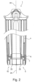
- the Figure 2 shows, by way of example, a water filter cartridge 1 with a filter housing 4, water inlet opening 10, a filter-side tank connection element 5 and a magnetic field guide element 23 arranged in its area.
- the magnetic field guide element 23 is arranged radially within an antenna 7 of an electronic communication element 6. By axially aligning it with respect to a longitudinal axis 24 of the water filter cartridge, magnetic field lines occurring in this area are bundled around this magnetic field guide element, and in particular in this, to form a significantly increased magnetic field.
- the magnetic field guide element 23 is formed in the area of the antenna 7, towards the connection-side front side of the water filter cartridge or its filter-side tank connection element 5, a targeted magnetic field guidance can thus be achieved, in particular towards an antenna of a complementary communication element, such as the antenna 18 of the device-side electronic communication element 19. This can bring about a significant improvement in the communication between these two antennas or the associated communication elements.
- a further embodiment of a magnetic field guide element 34 is shown on the right half of the illustration of the Figure 3 shown as an example. It has a longitudinal extension, Preferably, this extends in the longitudinal direction from the connection-side front side of the filter cartridge in the direction of the antenna 7 of the communication element 6. This longitudinal extension can also advantageously extend beyond the antenna 7. This can, on the one hand, result in better magnetic field conduction between this antenna 7 and a correspondingly complementary antenna.
- the section of this magnetic field conducting element 35 that lies outside the essentially direct communication path between the antennas offers a shielding effect, both inwards and outwards.
- this magnetic field conducting element 34 is sleeve-shaped.
- a separating layer 35 is provided here again as an example for all possible embodiments.
- the separating layers 35 on the magnetic field conducting elements 25 and 27 are shown as examples of such a separating layer.
- the Figure 3 shows a partial sectional view of a filter-side tank connection element 5 of a water filter cartridge 1.
- an electronic communication element with antenna 7 is shown, which antenna is, for example, ring-shaped and can therefore also be seen in its sectional view in the left half of the image.
- the magnetic field guide element 25 is, as the embodiment in the Figure 2 , arranged radially inside the antenna 7 and extending axially in the water filter cartridge. This can therefore also be used to create a magnetic field line concentration within the water filter cartridge 1 and its surroundings.
- This magnetic field conducting element 25 can, for example, interact with a further magnetic field conducting element 26, which is also designed to extend axially in the longitudinal direction and which, in this example, is arranged radially further out in the water filter housing 4 than the magnetic field conducting element 25.
- the reason for this can, for example, be a radial expansion of the structures in the connection area.
- these two magnetic field conducting elements can, for example, each represent two sleeve-shaped embodiments, which can be arranged at the relevant positions within the filter cartridge. For example, by plugging them onto an element for the outlet of the water treated by the water filter cartridge.
- a further embodiment is shown on the left half of the image by the magnetic field guide element 27, which extends from the antenna to the front end of the filter-side tank connection element.
- This embodiment has the advantage that a continuous magnetic field line line is possible in this area. This can be implemented, for example, by coating a corresponding inner area of the water filter cartridge, or by a correspondingly shaped sleeve.
- a further possible embodiment is shown by the magnetic field guide element 28, which is arranged radially outside the antenna 7 in and/or on a region of the filter cartridge housing 4.
- This can, on the one hand, provide a shielding of magnetic field lines occurring inside the filter cartridge from the outside, and, on the other hand, a shielding possibly from the outside magnetic field lines, which could otherwise interfere with the communication of the antennas.
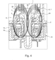
- FIG. 4 shows a tank 2 with a filter connection element 8 on the tank side and a water filter cartridge 1 connected to it with its filter-side tank connection element 5 and a tank-side device connection element 15 and a device-side tank connection element 16 connected to it.
- a magnetic field conducting element 30 is shown in the central area of the water filter cartridges, water tank and the respective connection elements 5, 8 and 15, 16.
- magnetic field lines 29 are drawn in, which run between the two antennas 7 and 18.
- the magnetic field conducting element 30 causes a concentration of the magnetic field lines in its interior. This means that the magnetic field in this area can be significantly concentrated or strengthened. In addition, this effect can reduce disruptive influences from outside. Disturbances, such as those caused by water-related imbalances, can also be significantly reduced in their effect.
- This magnetic field conducting element can, for example, be arranged in the area of the water discharge from the tank, e.g. inserted into the tank outlet opening 13.
- a sealing means can be arranged between the magnetic field conducting element 30 and the tank outlet opening 13.
- Such an embodiment can be realized, for example, as a plug-in connection.
- the magnetic field conducting element itself is preferably designed in the form of a sleeve, so that on the one hand an optimal magnetic field conduction can take place in the wall of the sleeve and on the other hand a A fluid-carrying connection can be made between the tank outlet and the device-side water connection.
- a valve can also be provided in the tank outlet opening, which closes the tank if the device-side tank connection is not connected to a device-side tank connection. This also applies to all possible versions of the water tanks described here.
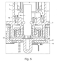
- the Figure 5 shows the same structure as the Figure 4 .
- a further magnetic field conducting element 31 is shown here, essentially in the form of a disk or a ring. It is arranged on the side outside the device connection-side antenna 18 with respect to the magnetic field formed by its magnetic field lines 29. This means that it can capture field lines radiating in this direction and, via a possible contact point with the magnetic field conducting element 30, introduce the magnetic field thus formed into the latter, further amplifying it.
- a further effect here is additional shielding both inwards and outwards.
- the magnetic field conducting element 31 can be provided both in addition to the magnetic field conducting element 30 and, in a possible alternative embodiment, without it.
- the Figure 6 shows a modification of the one in the Figure 5 shown version.
- the magnetic field guide element 31 shown here has been modified to form a pot-shaped magnetic field guide element 32.
- This encloses with its outer sleeve-shaped wall the tank-side filter connection element 8 and the antenna 18 arranged therein for the device-side electronic communication element (cf. Figure 1 ). Due to this pot-shaped design of the magnetic field guide element 32, the entire interior of the device-side tank connection element 16 can be magnetically This can result in a further improvement in the communication between the two antennas 18 and 7. The same also applies to the improvement in the reduction of electromagnetic interference.
- a further magnetic field guide element 33 is arranged in the tank 2, for example. It is preferably aligned with the wall of the pot-shaped magnetic field guide element 32 in the device-side tank connection element 16 and also preferably extends to near the height at which the antenna 7 of the filter-side electronic communication element 6 is positioned when plugged into the tank.
- the magnetic field guide element 33 also preferably extends a little further in the axial direction beyond it, so that on the one hand the escape of magnetic field lines into this area can at least be contained and on the other hand a shield against magnetic interference from the outside can also be achieved.
Landscapes
- Life Sciences & Earth Sciences (AREA)
- Hydrology & Water Resources (AREA)
- Engineering & Computer Science (AREA)
- Environmental & Geological Engineering (AREA)
- Water Supply & Treatment (AREA)
- Chemical & Material Sciences (AREA)
- Organic Chemistry (AREA)
- Water Treatment By Electricity Or Magnetism (AREA)
- Separation Using Semi-Permeable Membranes (AREA)
Claims (13)
- Cartouche de filtre à eau (1) destinée à être insérée dans un réservoir de stockage d'eau (2) d'un dispositif de transport d'eau (3), ladite cartouche comprenant un boîtier de filtre (4), un élément de raccordement de réservoir côté filtre (5) et un élément de communication électronique (6) pourvu d'une antenne (7), caractérisée en ce qu'un élément conducteur de champ magnétique (23) est prévu et en ce que l'élément conducteur de champ magnétique (23) est disposé dans une zone de la cartouche de filtre à eau (1) qui est située entre l'antenne (7) de l'élément de communication électronique côté filtre (6) et un emplacement sur la cartouche de filtre à eau (1), lequel emplacement, lorsque la cartouche de filtre à eau (1) est insérée, pointe en direction de l'antenne (18) d'un élément de communication complémentaire côté réservoir et/ou d'élément de communication complémentaire côté dispositif (19) qui sont prévus pour communiquer avec l'élément de communication côté filtre (6).
- Cartouche de filtre à eau (1) selon la revendication 1, caractérisée en ce que l'élément conducteur de champ magnétique (23, 25 à 34) présente une structure à extension longitudinale axiale, notamment en forme de broche, de fil ou similaire.
- Cartouche de filtre à eau (1) selon l'une des revendications 1 à 2, caractérisée en ce que l'élément conducteur de champ magnétique (23, 25 à 34) ou une pluralité d'éléments conducteurs de champ magnétique (23, 25 à 34), vus en coupe transversale, forment une structure conductrice de champ magnétique au moins partiellement annulaire, notamment du type cage.
- Cartouche de filtre à eau (1) selon l'une des revendications 1 à 3, caractérisée en ce que l'élément conducteur de champ magnétique (23, 25 à 34) est en forme de manchon.
- Cartouche de filtre à eau (1) selon l'une des revendications 1 à 4, caractérisée en ce que l'élément conducteur de champ magnétique (23, 25 à 34) est conçu comme un revêtement dans et/ou sur la cartouche de filtre à eau (1).
- Cartouche de filtre à eau (1) selon l'une des revendications 1 à 5, caractérisée en ce qu'une couche séparatrice (35) est prévue entre un élément conducteur de champ magnétique (23, 25 à 34) et une zone de transport d'eau.
- Cartouche de filtre à eau (1) selon l'une des revendications 1 à 6, caractérisée en ce que l'élément conducteur de champ magnétique (23, 25 à 34) est disposé dans la zone de l'élément de raccordement de réservoir côté filtre (5), notamment dans et/ou sur le boîtier de filtre (4).
- Cartouche de filtre à eau (1) selon l'une des revendications 1 à 7, caractérisée en ce que l'élément conducteur de champ magnétique (23, 25 à 34) est disposé dans la zone d'une ouverture de sortie d'eau (11) de la cartouche de filtre à eau (1).
- Réservoir à eau (2) destiné à stocker de l'eau potable destiné à un dispositif de transport d'eau (3), en particulier une machine à boissons, ledit réservoir comprenant un boîtier de réservoir, une ouverture de sortie de réservoir (13) et un élément de raccordement de filtre côté réservoir (8), caractérisé en ce qu'un élément conducteur de champ magnétique (30, 33) est prévu.
- Réservoir d'eau (2) selon la revendication 9, caractérisé en ce que l'élément conducteur de champ magnétique (30, 33) est disposé dans et/ou sur l'élément de raccordement de filtre côté réservoir (8) et/ou sur l'ouverture de sortie de réservoir. (13).
- Réservoir d'eau (2) selon l'une des revendications 9 ou 10, caractérisé en ce que l'élément conducteur de champ magnétique (30, 33) est disposé dans la zone d'un élément de raccordement de dispositif côté réservoir (15) .
- Réservoir d'eau (2) selon l'une des revendications 9 à 11, caractérisé en ce qu'un élément de communication électronique pourvu d'une antenne est prévu.
- Dispositif de transport d'eau (3), en particulier machine à boissons, comprenant un réservoir d'eau (2), un élément de raccordement de réservoir côté machine (16) destiné au raccordement au réservoir d'eau (2), un moyen de communication électronique (19) pourvu d'une antenne et une cartouche de filtre à eau (1) insérée dans le réservoir d'eau (2), caractérisé en ce qu'un élément conducteur de champ magnétique (23, 25 à 34) est disposé dans une zone située entre deux antennes (7, 18) .
Applications Claiming Priority (1)
| Application Number | Priority Date | Filing Date | Title |
|---|---|---|---|
| DE102015105403.5A DE102015105403B4 (de) | 2015-04-09 | 2015-04-09 | Wasserfilterpatrone, Wassertank und wasserführendes Gerät |
Publications (3)
| Publication Number | Publication Date |
|---|---|
| EP3078638A1 EP3078638A1 (fr) | 2016-10-12 |
| EP3078638C0 EP3078638C0 (fr) | 2024-05-01 |
| EP3078638B1 true EP3078638B1 (fr) | 2024-05-01 |
Family
ID=55701699
Family Applications (1)
| Application Number | Title | Priority Date | Filing Date |
|---|---|---|---|
| EP16159547.5A Active EP3078638B1 (fr) | 2015-04-09 | 2016-03-10 | Cartouche de filtre a eau et reservoir a eau |
Country Status (2)
| Country | Link |
|---|---|
| EP (1) | EP3078638B1 (fr) |
| DE (1) | DE102015105403B4 (fr) |
Families Citing this family (3)
| Publication number | Priority date | Publication date | Assignee | Title |
|---|---|---|---|---|
| WO2021041900A1 (fr) * | 2019-08-28 | 2021-03-04 | Kx Technologies, Llc | Interconnexions de filtre utilisant une force de cisaillement magnétique générée par des aimants programmés (polymagnets) codés |
| EP4096805A4 (fr) * | 2020-04-21 | 2023-12-20 | KX Technologies LLC | Interconnexion de filtre alimenté par gravité utilisant des aimants programmés (polymagnets) codés |
| BE1030170B1 (de) | 2022-01-10 | 2023-08-10 | Miele & Cie | Filtereinheit, Wasserführender Automat mit einer derartigen Filtereinheit, Verfahren zur Erkennung des Gebrauchszustandes einer Filtereinheit und Verfahren zur Bestimmung der Lebensdauer einer Filtereinheit |
Family Cites Families (5)
| Publication number | Priority date | Publication date | Assignee | Title |
|---|---|---|---|---|
| DE102006029105A1 (de) | 2005-06-22 | 2006-12-28 | Aquis Wasser-Luftsysteme GmbH Lindau, Zweigniederlassung Rebstein | Filterpatrone |
| EP1834927B8 (fr) * | 2006-03-17 | 2019-06-26 | Aquis Wasser-Luft-Systeme GmbH, Lindau, Zweigniederlassung Rebstein | Appareil de traitement de l'eau comprenant un dispositif mélangeur |
| US7699989B2 (en) * | 2006-10-17 | 2010-04-20 | Millipore Corporation | Powered cartridges and other devices within housings |
| DE102014117720A1 (de) | 2014-12-02 | 2016-06-02 | Aquis Wasser-Luft-Systeme Gmbh, Lindau, Zweigniederlassung Rebstein | Getränkemaschine mit Wassertank |
| DE102014117725A1 (de) | 2014-12-02 | 2016-06-02 | Aquis Wasser-Luft-Systeme Gmbh, Lindau, Zweigniederlassung Rebstein | Filter zum Einsetzen in einen Wasservorratstank eines Haushaltsgerätes, insbesondere einer Getränkemaschine |
-
2015
- 2015-04-09 DE DE102015105403.5A patent/DE102015105403B4/de active Active
-
2016
- 2016-03-10 EP EP16159547.5A patent/EP3078638B1/fr active Active
Also Published As
| Publication number | Publication date |
|---|---|
| EP3078638C0 (fr) | 2024-05-01 |
| DE102015105403A1 (de) | 2016-10-13 |
| DE102015105403B4 (de) | 2022-05-12 |
| EP3078638A1 (fr) | 2016-10-12 |
Similar Documents
| Publication | Publication Date | Title |
|---|---|---|
| EP2433906B1 (fr) | Cartouche de filtre à eau | |
| EP2088906B1 (fr) | Réservoir avec cartouche filtrante | |
| EP4208276B1 (fr) | Filtre comportant un dispositif de centrage | |
| DE102008010914A1 (de) | Getränkemaschine mit einem Wassertank und einer Wasserfilterkartusche | |
| EP2604321A1 (fr) | Dispositif de filtre | |
| DE102015105403B4 (de) | Wasserfilterpatrone, Wassertank und wasserführendes Gerät | |
| EP2759236B1 (fr) | Chauffage à couche épaisse et adapteur pour | |
| DE102017003489A1 (de) | Filtervorrichtung | |
| EP4208278B1 (fr) | Cartouche filtrante | |
| EP3028612B1 (fr) | Filtre à monter dans un réservoir d'eau d'un appareil ménager, en particulier une machine à boisson | |
| EP4312681B1 (fr) | Filtre comprenant un dispositif de centrage | |
| EP3105188B1 (fr) | Dispositif de traitement de l'eau | |
| DE102016124928A1 (de) | Landwirtschaftliche Erntemaschine | |
| EP3028611B1 (fr) | Machine a boisson et reservoir d'eau | |
| DE102011081502A1 (de) | Kühlschmiermittelzuführungssystem | |
| EP3180291B1 (fr) | Cartouche de traitement d'eau pour dispositif à vapeur et dispositif à vapeur | |
| DE102019008741A1 (de) | Filtervorrichtung | |
| DE102017201683A1 (de) | Kraftstofffiltereinrichtung | |
| EP2049217B1 (fr) | Cartouche filtrante pour des appareils à débit d'eau | |
| DE202019103210U1 (de) | Filtervorrichtung | |
| DE102016102795A1 (de) | Filterelement und Milchaufschäumer mit einem Filterelement | |
| DE102011112052A1 (de) | Trinkwasserfilter, insbesondere rückspülbares Trinkwasserfilter | |
| EP3085399A1 (fr) | Cartouche de concentré sec de dialysat | |
| DE20111516U1 (de) | Halteplatte für Staubbeutel und/oder -tüten für Staubsauger | |
| DE102014002505A1 (de) | Anordnung zum Reinigen von Wasser |
Legal Events
| Date | Code | Title | Description |
|---|---|---|---|
| PUAI | Public reference made under article 153(3) epc to a published international application that has entered the european phase |
Free format text: ORIGINAL CODE: 0009012 |
|
| AK | Designated contracting states |
Kind code of ref document: A1 Designated state(s): AL AT BE BG CH CY CZ DE DK EE ES FI FR GB GR HR HU IE IS IT LI LT LU LV MC MK MT NL NO PL PT RO RS SE SI SK SM TR |
|
| AX | Request for extension of the european patent |
Extension state: BA ME |
|
| STAA | Information on the status of an ep patent application or granted ep patent |
Free format text: STATUS: REQUEST FOR EXAMINATION WAS MADE |
|
| 17P | Request for examination filed |
Effective date: 20161121 |
|
| RBV | Designated contracting states (corrected) |
Designated state(s): AL AT BE BG CH CY CZ DE DK EE ES FI FR GB GR HR HU IE IS IT LI LT LU LV MC MK MT NL NO PL PT RO RS SE SI SK SM TR |
|
| STAA | Information on the status of an ep patent application or granted ep patent |
Free format text: STATUS: EXAMINATION IS IN PROGRESS |
|
| 17Q | First examination report despatched |
Effective date: 20180730 |
|
| RAP1 | Party data changed (applicant data changed or rights of an application transferred) |
Owner name: AQUIS WASSER-LUFT-SYSTEME GMBH, LINDAU, ZWEIGNIEDE |
|
| RAP3 | Party data changed (applicant data changed or rights of an application transferred) |
Owner name: ACLARIS WATER INNOVATIONS GMBH LINDAU, ZWEIGNIEDERLASSUNG REBSTEIN |
|
| GRAP | Despatch of communication of intention to grant a patent |
Free format text: ORIGINAL CODE: EPIDOSNIGR1 |
|
| STAA | Information on the status of an ep patent application or granted ep patent |
Free format text: STATUS: GRANT OF PATENT IS INTENDED |
|
| GRAJ | Information related to disapproval of communication of intention to grant by the applicant or resumption of examination proceedings by the epo deleted |
Free format text: ORIGINAL CODE: EPIDOSDIGR1 |
|
| STAA | Information on the status of an ep patent application or granted ep patent |
Free format text: STATUS: EXAMINATION IS IN PROGRESS |
|
| INTG | Intention to grant announced |
Effective date: 20231121 |
|
| GRAP | Despatch of communication of intention to grant a patent |
Free format text: ORIGINAL CODE: EPIDOSNIGR1 |
|
| STAA | Information on the status of an ep patent application or granted ep patent |
Free format text: STATUS: GRANT OF PATENT IS INTENDED |
|
| INTC | Intention to grant announced (deleted) | ||
| INTG | Intention to grant announced |
Effective date: 20240102 |
|
| GRAS | Grant fee paid |
Free format text: ORIGINAL CODE: EPIDOSNIGR3 |
|
| GRAA | (expected) grant |
Free format text: ORIGINAL CODE: 0009210 |
|
| STAA | Information on the status of an ep patent application or granted ep patent |
Free format text: STATUS: THE PATENT HAS BEEN GRANTED |
|
| AK | Designated contracting states |
Kind code of ref document: B1 Designated state(s): AL AT BE BG CH CY CZ DE DK EE ES FI FR GB GR HR HU IE IS IT LI LT LU LV MC MK MT NL NO PL PT RO RS SE SI SK SM TR |
|
| REG | Reference to a national code |
Ref country code: GB Ref legal event code: FG4D Free format text: NOT ENGLISH |
|
| REG | Reference to a national code |
Ref country code: CH Ref legal event code: EP |
|
| REG | Reference to a national code |
Ref country code: DE Ref legal event code: R096 Ref document number: 502016016495 Country of ref document: DE |
|
| REG | Reference to a national code |
Ref country code: IE Ref legal event code: FG4D Free format text: LANGUAGE OF EP DOCUMENT: GERMAN |
|
| RAP4 | Party data changed (patent owner data changed or rights of a patent transferred) |
Owner name: ACLARIS GMBH, LINDAU ZWEIGNIEDERLASSUNG REBSTEIN |
|
| U01 | Request for unitary effect filed |
Effective date: 20240501 |
|
| U07 | Unitary effect registered |
Designated state(s): AT BE BG DE DK EE FI FR IT LT LU LV MT NL PT SE SI Effective date: 20240507 |
|
| PG25 | Lapsed in a contracting state [announced via postgrant information from national office to epo] |
Ref country code: IS Free format text: LAPSE BECAUSE OF FAILURE TO SUBMIT A TRANSLATION OF THE DESCRIPTION OR TO PAY THE FEE WITHIN THE PRESCRIBED TIME-LIMIT Effective date: 20240901 |
|
| PG25 | Lapsed in a contracting state [announced via postgrant information from national office to epo] |
Ref country code: HR Free format text: LAPSE BECAUSE OF FAILURE TO SUBMIT A TRANSLATION OF THE DESCRIPTION OR TO PAY THE FEE WITHIN THE PRESCRIBED TIME-LIMIT Effective date: 20240501 |
|
| PG25 | Lapsed in a contracting state [announced via postgrant information from national office to epo] |
Ref country code: GR Free format text: LAPSE BECAUSE OF FAILURE TO SUBMIT A TRANSLATION OF THE DESCRIPTION OR TO PAY THE FEE WITHIN THE PRESCRIBED TIME-LIMIT Effective date: 20240802 |
|
| PG25 | Lapsed in a contracting state [announced via postgrant information from national office to epo] |
Ref country code: ES Free format text: LAPSE BECAUSE OF FAILURE TO SUBMIT A TRANSLATION OF THE DESCRIPTION OR TO PAY THE FEE WITHIN THE PRESCRIBED TIME-LIMIT Effective date: 20240501 |
|
| PG25 | Lapsed in a contracting state [announced via postgrant information from national office to epo] |
Ref country code: PL Free format text: LAPSE BECAUSE OF FAILURE TO SUBMIT A TRANSLATION OF THE DESCRIPTION OR TO PAY THE FEE WITHIN THE PRESCRIBED TIME-LIMIT Effective date: 20240501 |
|
| PG25 | Lapsed in a contracting state [announced via postgrant information from national office to epo] |
Ref country code: PL Free format text: LAPSE BECAUSE OF FAILURE TO SUBMIT A TRANSLATION OF THE DESCRIPTION OR TO PAY THE FEE WITHIN THE PRESCRIBED TIME-LIMIT Effective date: 20240501 Ref country code: NO Free format text: LAPSE BECAUSE OF FAILURE TO SUBMIT A TRANSLATION OF THE DESCRIPTION OR TO PAY THE FEE WITHIN THE PRESCRIBED TIME-LIMIT Effective date: 20240801 Ref country code: IS Free format text: LAPSE BECAUSE OF FAILURE TO SUBMIT A TRANSLATION OF THE DESCRIPTION OR TO PAY THE FEE WITHIN THE PRESCRIBED TIME-LIMIT Effective date: 20240901 Ref country code: HR Free format text: LAPSE BECAUSE OF FAILURE TO SUBMIT A TRANSLATION OF THE DESCRIPTION OR TO PAY THE FEE WITHIN THE PRESCRIBED TIME-LIMIT Effective date: 20240501 Ref country code: GR Free format text: LAPSE BECAUSE OF FAILURE TO SUBMIT A TRANSLATION OF THE DESCRIPTION OR TO PAY THE FEE WITHIN THE PRESCRIBED TIME-LIMIT Effective date: 20240802 Ref country code: ES Free format text: LAPSE BECAUSE OF FAILURE TO SUBMIT A TRANSLATION OF THE DESCRIPTION OR TO PAY THE FEE WITHIN THE PRESCRIBED TIME-LIMIT Effective date: 20240501 Ref country code: RS Free format text: LAPSE BECAUSE OF FAILURE TO SUBMIT A TRANSLATION OF THE DESCRIPTION OR TO PAY THE FEE WITHIN THE PRESCRIBED TIME-LIMIT Effective date: 20240801 |
|
| PG25 | Lapsed in a contracting state [announced via postgrant information from national office to epo] |
Ref country code: CZ Free format text: LAPSE BECAUSE OF FAILURE TO SUBMIT A TRANSLATION OF THE DESCRIPTION OR TO PAY THE FEE WITHIN THE PRESCRIBED TIME-LIMIT Effective date: 20240501 |
|
| PG25 | Lapsed in a contracting state [announced via postgrant information from national office to epo] |
Ref country code: RO Free format text: LAPSE BECAUSE OF FAILURE TO SUBMIT A TRANSLATION OF THE DESCRIPTION OR TO PAY THE FEE WITHIN THE PRESCRIBED TIME-LIMIT Effective date: 20240501 Ref country code: SK Free format text: LAPSE BECAUSE OF FAILURE TO SUBMIT A TRANSLATION OF THE DESCRIPTION OR TO PAY THE FEE WITHIN THE PRESCRIBED TIME-LIMIT Effective date: 20240501 |
|
| PG25 | Lapsed in a contracting state [announced via postgrant information from national office to epo] |
Ref country code: SM Free format text: LAPSE BECAUSE OF FAILURE TO SUBMIT A TRANSLATION OF THE DESCRIPTION OR TO PAY THE FEE WITHIN THE PRESCRIBED TIME-LIMIT Effective date: 20240501 |
|
| PG25 | Lapsed in a contracting state [announced via postgrant information from national office to epo] |
Ref country code: SM Free format text: LAPSE BECAUSE OF FAILURE TO SUBMIT A TRANSLATION OF THE DESCRIPTION OR TO PAY THE FEE WITHIN THE PRESCRIBED TIME-LIMIT Effective date: 20240501 Ref country code: SK Free format text: LAPSE BECAUSE OF FAILURE TO SUBMIT A TRANSLATION OF THE DESCRIPTION OR TO PAY THE FEE WITHIN THE PRESCRIBED TIME-LIMIT Effective date: 20240501 Ref country code: RO Free format text: LAPSE BECAUSE OF FAILURE TO SUBMIT A TRANSLATION OF THE DESCRIPTION OR TO PAY THE FEE WITHIN THE PRESCRIBED TIME-LIMIT Effective date: 20240501 Ref country code: CZ Free format text: LAPSE BECAUSE OF FAILURE TO SUBMIT A TRANSLATION OF THE DESCRIPTION OR TO PAY THE FEE WITHIN THE PRESCRIBED TIME-LIMIT Effective date: 20240501 |
|
| REG | Reference to a national code |
Ref country code: DE Ref legal event code: R097 Ref document number: 502016016495 Country of ref document: DE |
|
| PLBE | No opposition filed within time limit |
Free format text: ORIGINAL CODE: 0009261 |
|
| STAA | Information on the status of an ep patent application or granted ep patent |
Free format text: STATUS: NO OPPOSITION FILED WITHIN TIME LIMIT |
|
| 26N | No opposition filed |
Effective date: 20250204 |
|
| U20 | Renewal fee for the european patent with unitary effect paid |
Year of fee payment: 10 Effective date: 20250325 |
|
| PG25 | Lapsed in a contracting state [announced via postgrant information from national office to epo] |
Ref country code: MC Free format text: LAPSE BECAUSE OF FAILURE TO SUBMIT A TRANSLATION OF THE DESCRIPTION OR TO PAY THE FEE WITHIN THE PRESCRIBED TIME-LIMIT Effective date: 20240501 |
|
| REG | Reference to a national code |
Ref country code: CH Ref legal event code: H13 Free format text: ST27 STATUS EVENT CODE: U-0-0-H10-H13 (AS PROVIDED BY THE NATIONAL OFFICE) Effective date: 20251023 |
|
| GBPC | Gb: european patent ceased through non-payment of renewal fee |
Effective date: 20250310 |
|
| PG25 | Lapsed in a contracting state [announced via postgrant information from national office to epo] |
Ref country code: GB Free format text: LAPSE BECAUSE OF NON-PAYMENT OF DUE FEES Effective date: 20250310 |
|
| PG25 | Lapsed in a contracting state [announced via postgrant information from national office to epo] |
Ref country code: CH Free format text: LAPSE BECAUSE OF NON-PAYMENT OF DUE FEES Effective date: 20250331 |
|
| PG25 | Lapsed in a contracting state [announced via postgrant information from national office to epo] |
Ref country code: IE Free format text: LAPSE BECAUSE OF NON-PAYMENT OF DUE FEES Effective date: 20250310 |
|
| U20 | Renewal fee for the european patent with unitary effect paid |
Year of fee payment: 11 Effective date: 20260327 |