EP3078755B1 - Procédé de fabrication d'un anneau métallique pour courroie de transmission à variation continue - Google Patents
Procédé de fabrication d'un anneau métallique pour courroie de transmission à variation continue Download PDFInfo
- Publication number
- EP3078755B1 EP3078755B1 EP16163796.2A EP16163796A EP3078755B1 EP 3078755 B1 EP3078755 B1 EP 3078755B1 EP 16163796 A EP16163796 A EP 16163796A EP 3078755 B1 EP3078755 B1 EP 3078755B1
- Authority
- EP
- European Patent Office
- Prior art keywords
- metal ring
- layer
- nitrogen
- metal
- nitrided
- Prior art date
- Legal status (The legal status is an assumption and is not a legal conclusion. Google has not performed a legal analysis and makes no representation as to the accuracy of the status listed.)
- Active
Links
- 229910052751 metal Inorganic materials 0.000 title claims description 136
- 239000002184 metal Substances 0.000 title claims description 135
- 230000005540 biological transmission Effects 0.000 title claims description 27
- 238000004519 manufacturing process Methods 0.000 title claims description 25
- 230000002093 peripheral effect Effects 0.000 claims description 58
- 239000012298 atmosphere Substances 0.000 claims description 21
- 238000011282 treatment Methods 0.000 claims description 20
- 230000032683 aging Effects 0.000 claims description 19
- 239000000463 material Substances 0.000 claims description 19
- 238000005121 nitriding Methods 0.000 claims description 18
- 238000000137 annealing Methods 0.000 claims description 15
- 229910001240 Maraging steel Inorganic materials 0.000 claims description 12
- 238000005498 polishing Methods 0.000 claims description 10
- 239000002244 precipitate Substances 0.000 claims description 7
- 230000001590 oxidative effect Effects 0.000 claims description 6
- 238000005520 cutting process Methods 0.000 claims description 4
- 230000002950 deficient Effects 0.000 claims description 3
- 239000010410 layer Substances 0.000 description 130
- 230000000052 comparative effect Effects 0.000 description 21
- IJGRMHOSHXDMSA-UHFFFAOYSA-N Atomic nitrogen Chemical compound N#N IJGRMHOSHXDMSA-UHFFFAOYSA-N 0.000 description 20
- 125000004433 nitrogen atom Chemical group N* 0.000 description 14
- 239000002344 surface layer Substances 0.000 description 14
- 238000005299 abrasion Methods 0.000 description 8
- 239000010936 titanium Substances 0.000 description 8
- 229910052757 nitrogen Inorganic materials 0.000 description 7
- 229910052782 aluminium Inorganic materials 0.000 description 6
- 230000008859 change Effects 0.000 description 6
- 230000006866 deterioration Effects 0.000 description 6
- 229910001873 dinitrogen Inorganic materials 0.000 description 6
- 229910052719 titanium Inorganic materials 0.000 description 6
- 229910052774 Proactinium Inorganic materials 0.000 description 5
- 229910052745 lead Inorganic materials 0.000 description 5
- 238000000034 method Methods 0.000 description 5
- UFHFLCQGNIYNRP-UHFFFAOYSA-N Hydrogen Chemical compound [H][H] UFHFLCQGNIYNRP-UHFFFAOYSA-N 0.000 description 4
- QVGXLLKOCUKJST-UHFFFAOYSA-N atomic oxygen Chemical compound [O] QVGXLLKOCUKJST-UHFFFAOYSA-N 0.000 description 4
- PXHVJJICTQNCMI-UHFFFAOYSA-N nickel Substances [Ni] PXHVJJICTQNCMI-UHFFFAOYSA-N 0.000 description 4
- 239000001301 oxygen Substances 0.000 description 4
- 229910052760 oxygen Inorganic materials 0.000 description 4
- 230000035882 stress Effects 0.000 description 4
- 230000006835 compression Effects 0.000 description 3
- 238000007906 compression Methods 0.000 description 3
- 238000005530 etching Methods 0.000 description 3
- XEEYBQQBJWHFJM-UHFFFAOYSA-N iron Substances [Fe] XEEYBQQBJWHFJM-UHFFFAOYSA-N 0.000 description 3
- 229910052750 molybdenum Inorganic materials 0.000 description 3
- QGZKDVFQNNGYKY-UHFFFAOYSA-N Ammonia Chemical compound N QGZKDVFQNNGYKY-UHFFFAOYSA-N 0.000 description 2
- XKRFYHLGVUSROY-UHFFFAOYSA-N Argon Chemical compound [Ar] XKRFYHLGVUSROY-UHFFFAOYSA-N 0.000 description 2
- 229910000831 Steel Inorganic materials 0.000 description 2
- 229910000797 Ultra-high-strength steel Inorganic materials 0.000 description 2
- 125000004429 atom Chemical group 0.000 description 2
- 238000007542 hardness measurement Methods 0.000 description 2
- 230000005764 inhibitory process Effects 0.000 description 2
- 239000012299 nitrogen atmosphere Substances 0.000 description 2
- 238000001556 precipitation Methods 0.000 description 2
- 239000010959 steel Substances 0.000 description 2
- 239000000126 substance Substances 0.000 description 2
- OKTJSMMVPCPJKN-UHFFFAOYSA-N Carbon Chemical compound [C] OKTJSMMVPCPJKN-UHFFFAOYSA-N 0.000 description 1
- VYZAMTAEIAYCRO-UHFFFAOYSA-N Chromium Chemical compound [Cr] VYZAMTAEIAYCRO-UHFFFAOYSA-N 0.000 description 1
- ZOKXTWBITQBERF-UHFFFAOYSA-N Molybdenum Chemical compound [Mo] ZOKXTWBITQBERF-UHFFFAOYSA-N 0.000 description 1
- RTAQQCXQSZGOHL-UHFFFAOYSA-N Titanium Chemical compound [Ti] RTAQQCXQSZGOHL-UHFFFAOYSA-N 0.000 description 1
- XAGFODPZIPBFFR-UHFFFAOYSA-N aluminium Chemical compound [Al] XAGFODPZIPBFFR-UHFFFAOYSA-N 0.000 description 1
- 229910052786 argon Inorganic materials 0.000 description 1
- 238000005452 bending Methods 0.000 description 1
- 230000015572 biosynthetic process Effects 0.000 description 1
- 230000001680 brushing effect Effects 0.000 description 1
- 229910052799 carbon Inorganic materials 0.000 description 1
- 229910052804 chromium Inorganic materials 0.000 description 1
- 239000010941 cobalt Substances 0.000 description 1
- 229910017052 cobalt Inorganic materials 0.000 description 1
- GUTLYIVDDKVIGB-UHFFFAOYSA-N cobalt atom Chemical compound [Co] GUTLYIVDDKVIGB-UHFFFAOYSA-N 0.000 description 1
- 230000000694 effects Effects 0.000 description 1
- 230000002349 favourable effect Effects 0.000 description 1
- 239000007789 gas Substances 0.000 description 1
- 239000011261 inert gas Substances 0.000 description 1
- 229910052742 iron Inorganic materials 0.000 description 1
- 238000003475 lamination Methods 0.000 description 1
- 230000007246 mechanism Effects 0.000 description 1
- 238000002156 mixing Methods 0.000 description 1
- 239000000203 mixture Substances 0.000 description 1
- 239000011733 molybdenum Substances 0.000 description 1
- 229910052759 nickel Inorganic materials 0.000 description 1
- 230000008569 process Effects 0.000 description 1
- 230000009467 reduction Effects 0.000 description 1
- 230000000452 restraining effect Effects 0.000 description 1
- 238000005979 thermal decomposition reaction Methods 0.000 description 1
- 238000003466 welding Methods 0.000 description 1
- 238000004804 winding Methods 0.000 description 1
Images



Classifications
-
- F—MECHANICAL ENGINEERING; LIGHTING; HEATING; WEAPONS; BLASTING
- F16—ENGINEERING ELEMENTS AND UNITS; GENERAL MEASURES FOR PRODUCING AND MAINTAINING EFFECTIVE FUNCTIONING OF MACHINES OR INSTALLATIONS; THERMAL INSULATION IN GENERAL
- F16G—BELTS, CABLES, OR ROPES, PREDOMINANTLY USED FOR DRIVING PURPOSES; CHAINS; FITTINGS PREDOMINANTLY USED THEREFOR
- F16G5/00—V-belts, i.e. belts of tapered cross-section
- F16G5/16—V-belts, i.e. belts of tapered cross-section consisting of several parts
-
- B—PERFORMING OPERATIONS; TRANSPORTING
- B21—MECHANICAL METAL-WORKING WITHOUT ESSENTIALLY REMOVING MATERIAL; PUNCHING METAL
- B21D—WORKING OR PROCESSING OF SHEET METAL OR METAL TUBES, RODS OR PROFILES WITHOUT ESSENTIALLY REMOVING MATERIAL; PUNCHING METAL
- B21D53/00—Making other particular articles
- B21D53/14—Making other particular articles belts, e.g. machine-gun belts
-
- C—CHEMISTRY; METALLURGY
- C21—METALLURGY OF IRON
- C21D—MODIFYING THE PHYSICAL STRUCTURE OF FERROUS METALS; GENERAL DEVICES FOR HEAT TREATMENT OF FERROUS OR NON-FERROUS METALS OR ALLOYS; MAKING METAL MALLEABLE, e.g. BY DECARBURISATION OR TEMPERING
- C21D1/00—General methods or devices for heat treatment, e.g. annealing, hardening, quenching or tempering
- C21D1/06—Surface hardening
-
- C—CHEMISTRY; METALLURGY
- C21—METALLURGY OF IRON
- C21D—MODIFYING THE PHYSICAL STRUCTURE OF FERROUS METALS; GENERAL DEVICES FOR HEAT TREATMENT OF FERROUS OR NON-FERROUS METALS OR ALLOYS; MAKING METAL MALLEABLE, e.g. BY DECARBURISATION OR TEMPERING
- C21D1/00—General methods or devices for heat treatment, e.g. annealing, hardening, quenching or tempering
- C21D1/74—Methods of treatment in inert gas, controlled atmosphere, vacuum or pulverulent material
-
- C—CHEMISTRY; METALLURGY
- C21—METALLURGY OF IRON
- C21D—MODIFYING THE PHYSICAL STRUCTURE OF FERROUS METALS; GENERAL DEVICES FOR HEAT TREATMENT OF FERROUS OR NON-FERROUS METALS OR ALLOYS; MAKING METAL MALLEABLE, e.g. BY DECARBURISATION OR TEMPERING
- C21D1/00—General methods or devices for heat treatment, e.g. annealing, hardening, quenching or tempering
- C21D1/74—Methods of treatment in inert gas, controlled atmosphere, vacuum or pulverulent material
- C21D1/76—Adjusting the composition of the atmosphere
-
- C—CHEMISTRY; METALLURGY
- C21—METALLURGY OF IRON
- C21D—MODIFYING THE PHYSICAL STRUCTURE OF FERROUS METALS; GENERAL DEVICES FOR HEAT TREATMENT OF FERROUS OR NON-FERROUS METALS OR ALLOYS; MAKING METAL MALLEABLE, e.g. BY DECARBURISATION OR TEMPERING
- C21D9/00—Heat treatment, e.g. annealing, hardening, quenching or tempering, adapted for particular articles; Furnaces therefor
- C21D9/40—Heat treatment, e.g. annealing, hardening, quenching or tempering, adapted for particular articles; Furnaces therefor for rings; for bearing races
-
- C—CHEMISTRY; METALLURGY
- C23—COATING METALLIC MATERIAL; COATING MATERIAL WITH METALLIC MATERIAL; CHEMICAL SURFACE TREATMENT; DIFFUSION TREATMENT OF METALLIC MATERIAL; COATING BY VACUUM EVAPORATION, BY SPUTTERING, BY ION IMPLANTATION OR BY CHEMICAL VAPOUR DEPOSITION, IN GENERAL; INHIBITING CORROSION OF METALLIC MATERIAL OR INCRUSTATION IN GENERAL
- C23C—COATING METALLIC MATERIAL; COATING MATERIAL WITH METALLIC MATERIAL; SURFACE TREATMENT OF METALLIC MATERIAL BY DIFFUSION INTO THE SURFACE, BY CHEMICAL CONVERSION OR SUBSTITUTION; COATING BY VACUUM EVAPORATION, BY SPUTTERING, BY ION IMPLANTATION OR BY CHEMICAL VAPOUR DEPOSITION, IN GENERAL
- C23C28/00—Coating for obtaining at least two superposed coatings either by methods not provided for in a single one of groups C23C2/00 - C23C26/00 or by combinations of methods provided for in subclasses C23C and C25C or C25D
- C23C28/04—Coating for obtaining at least two superposed coatings either by methods not provided for in a single one of groups C23C2/00 - C23C26/00 or by combinations of methods provided for in subclasses C23C and C25C or C25D only coatings of inorganic non-metallic material
-
- C—CHEMISTRY; METALLURGY
- C23—COATING METALLIC MATERIAL; COATING MATERIAL WITH METALLIC MATERIAL; CHEMICAL SURFACE TREATMENT; DIFFUSION TREATMENT OF METALLIC MATERIAL; COATING BY VACUUM EVAPORATION, BY SPUTTERING, BY ION IMPLANTATION OR BY CHEMICAL VAPOUR DEPOSITION, IN GENERAL; INHIBITING CORROSION OF METALLIC MATERIAL OR INCRUSTATION IN GENERAL
- C23C—COATING METALLIC MATERIAL; COATING MATERIAL WITH METALLIC MATERIAL; SURFACE TREATMENT OF METALLIC MATERIAL BY DIFFUSION INTO THE SURFACE, BY CHEMICAL CONVERSION OR SUBSTITUTION; COATING BY VACUUM EVAPORATION, BY SPUTTERING, BY ION IMPLANTATION OR BY CHEMICAL VAPOUR DEPOSITION, IN GENERAL
- C23C8/00—Solid state diffusion of only non-metal elements into metallic material surfaces; Chemical surface treatment of metallic material by reaction of the surface with a reactive gas, leaving reaction products of surface material in the coating, e.g. conversion coatings, passivation of metals
- C23C8/02—Pretreatment of the material to be coated
-
- C—CHEMISTRY; METALLURGY
- C23—COATING METALLIC MATERIAL; COATING MATERIAL WITH METALLIC MATERIAL; CHEMICAL SURFACE TREATMENT; DIFFUSION TREATMENT OF METALLIC MATERIAL; COATING BY VACUUM EVAPORATION, BY SPUTTERING, BY ION IMPLANTATION OR BY CHEMICAL VAPOUR DEPOSITION, IN GENERAL; INHIBITING CORROSION OF METALLIC MATERIAL OR INCRUSTATION IN GENERAL
- C23C—COATING METALLIC MATERIAL; COATING MATERIAL WITH METALLIC MATERIAL; SURFACE TREATMENT OF METALLIC MATERIAL BY DIFFUSION INTO THE SURFACE, BY CHEMICAL CONVERSION OR SUBSTITUTION; COATING BY VACUUM EVAPORATION, BY SPUTTERING, BY ION IMPLANTATION OR BY CHEMICAL VAPOUR DEPOSITION, IN GENERAL
- C23C8/00—Solid state diffusion of only non-metal elements into metallic material surfaces; Chemical surface treatment of metallic material by reaction of the surface with a reactive gas, leaving reaction products of surface material in the coating, e.g. conversion coatings, passivation of metals
- C23C8/06—Solid state diffusion of only non-metal elements into metallic material surfaces; Chemical surface treatment of metallic material by reaction of the surface with a reactive gas, leaving reaction products of surface material in the coating, e.g. conversion coatings, passivation of metals using gases
- C23C8/08—Solid state diffusion of only non-metal elements into metallic material surfaces; Chemical surface treatment of metallic material by reaction of the surface with a reactive gas, leaving reaction products of surface material in the coating, e.g. conversion coatings, passivation of metals using gases only one element being applied
- C23C8/24—Nitriding
-
- C—CHEMISTRY; METALLURGY
- C23—COATING METALLIC MATERIAL; COATING MATERIAL WITH METALLIC MATERIAL; CHEMICAL SURFACE TREATMENT; DIFFUSION TREATMENT OF METALLIC MATERIAL; COATING BY VACUUM EVAPORATION, BY SPUTTERING, BY ION IMPLANTATION OR BY CHEMICAL VAPOUR DEPOSITION, IN GENERAL; INHIBITING CORROSION OF METALLIC MATERIAL OR INCRUSTATION IN GENERAL
- C23C—COATING METALLIC MATERIAL; COATING MATERIAL WITH METALLIC MATERIAL; SURFACE TREATMENT OF METALLIC MATERIAL BY DIFFUSION INTO THE SURFACE, BY CHEMICAL CONVERSION OR SUBSTITUTION; COATING BY VACUUM EVAPORATION, BY SPUTTERING, BY ION IMPLANTATION OR BY CHEMICAL VAPOUR DEPOSITION, IN GENERAL
- C23C8/00—Solid state diffusion of only non-metal elements into metallic material surfaces; Chemical surface treatment of metallic material by reaction of the surface with a reactive gas, leaving reaction products of surface material in the coating, e.g. conversion coatings, passivation of metals
- C23C8/06—Solid state diffusion of only non-metal elements into metallic material surfaces; Chemical surface treatment of metallic material by reaction of the surface with a reactive gas, leaving reaction products of surface material in the coating, e.g. conversion coatings, passivation of metals using gases
- C23C8/08—Solid state diffusion of only non-metal elements into metallic material surfaces; Chemical surface treatment of metallic material by reaction of the surface with a reactive gas, leaving reaction products of surface material in the coating, e.g. conversion coatings, passivation of metals using gases only one element being applied
- C23C8/24—Nitriding
- C23C8/26—Nitriding of ferrous surfaces
-
- F—MECHANICAL ENGINEERING; LIGHTING; HEATING; WEAPONS; BLASTING
- F16—ENGINEERING ELEMENTS AND UNITS; GENERAL MEASURES FOR PRODUCING AND MAINTAINING EFFECTIVE FUNCTIONING OF MACHINES OR INSTALLATIONS; THERMAL INSULATION IN GENERAL
- F16H—GEARING
- F16H9/00—Gearings for conveying rotary motion with variable gear ratio, or for reversing rotary motion, by endless flexible members
- F16H9/02—Gearings for conveying rotary motion with variable gear ratio, or for reversing rotary motion, by endless flexible members without members having orbital motion
- F16H9/04—Gearings for conveying rotary motion with variable gear ratio, or for reversing rotary motion, by endless flexible members without members having orbital motion using belts, V-belts, or ropes
-
- F—MECHANICAL ENGINEERING; LIGHTING; HEATING; WEAPONS; BLASTING
- F16—ENGINEERING ELEMENTS AND UNITS; GENERAL MEASURES FOR PRODUCING AND MAINTAINING EFFECTIVE FUNCTIONING OF MACHINES OR INSTALLATIONS; THERMAL INSULATION IN GENERAL
- F16H—GEARING
- F16H9/00—Gearings for conveying rotary motion with variable gear ratio, or for reversing rotary motion, by endless flexible members
- F16H9/02—Gearings for conveying rotary motion with variable gear ratio, or for reversing rotary motion, by endless flexible members without members having orbital motion
- F16H9/04—Gearings for conveying rotary motion with variable gear ratio, or for reversing rotary motion, by endless flexible members without members having orbital motion using belts, V-belts, or ropes
- F16H9/12—Gearings for conveying rotary motion with variable gear ratio, or for reversing rotary motion, by endless flexible members without members having orbital motion using belts, V-belts, or ropes engaging a pulley built-up out of relatively axially-adjustable parts in which the belt engages the opposite flanges of the pulley directly without interposed belt-supporting members
- F16H9/16—Gearings for conveying rotary motion with variable gear ratio, or for reversing rotary motion, by endless flexible members without members having orbital motion using belts, V-belts, or ropes engaging a pulley built-up out of relatively axially-adjustable parts in which the belt engages the opposite flanges of the pulley directly without interposed belt-supporting members using two pulleys, both built-up out of adjustable conical parts
- F16H9/18—Gearings for conveying rotary motion with variable gear ratio, or for reversing rotary motion, by endless flexible members without members having orbital motion using belts, V-belts, or ropes engaging a pulley built-up out of relatively axially-adjustable parts in which the belt engages the opposite flanges of the pulley directly without interposed belt-supporting members using two pulleys, both built-up out of adjustable conical parts only one flange of each pulley being adjustable
-
- F—MECHANICAL ENGINEERING; LIGHTING; HEATING; WEAPONS; BLASTING
- F16—ENGINEERING ELEMENTS AND UNITS; GENERAL MEASURES FOR PRODUCING AND MAINTAINING EFFECTIVE FUNCTIONING OF MACHINES OR INSTALLATIONS; THERMAL INSULATION IN GENERAL
- F16H—GEARING
- F16H9/00—Gearings for conveying rotary motion with variable gear ratio, or for reversing rotary motion, by endless flexible members
- F16H9/02—Gearings for conveying rotary motion with variable gear ratio, or for reversing rotary motion, by endless flexible members without members having orbital motion
- F16H9/24—Gearings for conveying rotary motion with variable gear ratio, or for reversing rotary motion, by endless flexible members without members having orbital motion using chains or toothed belts, belts in the form of links; Chains or belts specially adapted to such gearing
-
- C—CHEMISTRY; METALLURGY
- C21—METALLURGY OF IRON
- C21D—MODIFYING THE PHYSICAL STRUCTURE OF FERROUS METALS; GENERAL DEVICES FOR HEAT TREATMENT OF FERROUS OR NON-FERROUS METALS OR ALLOYS; MAKING METAL MALLEABLE, e.g. BY DECARBURISATION OR TEMPERING
- C21D2221/00—Treating localised areas of an article
- C21D2221/10—Differential treatment of inner with respect to outer regions, e.g. core and periphery, respectively
Definitions
- the invention relates to a manufacturing method for a metal ring, especially to a manufacturing method for a metal ring for a transmission belt of a belt-type continuously variable transmission.
- a transmission belt in the steel belt-type CVT has a structure in which a number of elements are lined up without space between them and attached to a metal ring laminate that is made from a plurality of thin-sheet metal rings laminated in a nested state. Tension of the metal ring laminate presses the elements against input-side and output-side pulleys, thereby transmitting power from the input-side pulley to the output-side pulley.
- nitrided layers are formed in main surfaces (inner and outer peripheral surfaces) and end surfaces of the metal ring.
- the nitrided layers formed in the end surfaces become thicker than the nitrided layers formed in the main surfaces (nitrided layers in the main surface parts).
- thicknesses of the nitrided layers in the end parts become large, residual tensile stress in non-nitrided parts on inner sides of the nitrided layers of the end parts becomes large, and there is thus a possibility that fatigue fracture starting from the end parts could happen easily.
- WO 2011/135624 A1 discloses a metal ring in which a thickness of a nitrided layer in an end part is reduced by forming a nitriding inhibition film on an end surface before nitriding. Because the thickness of the nitrided layer of the end part is reduced, fatigue fracture starting from the end part is restrained.
- the inventors found the following problem in terms of a metal ring that is used for a transmission belt in a belt-type continuously variable transmission, and a manufacturing method for the metal ring. Because one of end surfaces of a metal ring is in contact with elements, abrasion resistance is required. In the metal ring disclosed in WO 2011/135624 A1 , since the thickness of the nitrided layer in the end part is reduced, surface hardness of the end surface is reduced, and, as a result, abrasion resistance of the end surface could be deteriorated.
- the invention restrains fatigue fracture starting from an end part, and restrains deterioration of abrasion resistance of an end surface.
- a manufacturing method for a metal ring according to the invention is a manufacturing method for a metal ring for a transmission belt of a belt-type continuously variable transmission.
- the manufacturing method includes forming a concentrated layer in a main surface of a material of the metal ring, in which nitrogen-affinitive metal is concentrated in the concentrated layer, removing the concentrated layer, thereby exposing a depletion layer on the main surface, in which nitrogen-affinitive metal is deficient in the depletion layer, exposing a bulk layer on an end surface of the metal ring after the concentrated layer is formed, and nitriding the metal ring in which the depletion layer is exposed on the main surface and the bulk layer is exposed on the end surface.
- a concentration of the nitrogen-affinitive metal in the end surface is higher than a concentration of the nitrogen-affinitive metal in the main surface. Since the concentration of the nitrogen-affinitive metal is high in the end surface, a lot of nitrogen atoms are trapped due to nitriding, thus achieving the second nitrided layer that is thin but also hard. Therefore, it is possible to restrain fatigue fracture starting from the end part, and it is also possible to restrain deterioration of abrasion resistance in the end surface.
- the manufacturing method may further include performing aging treatment of the metal ring in which the depletion layer is exposed on the main surface and the bulk layer is exposed on the end surface, before nitriding, and the metal ring may contain maraging steel containing the nitrogen-affinitive metal that does not precipitate during the aging treatment. Also, Cr may be contained as the nitrogen-affinitive metal.
- the concentrated layer may be formed by performing annealing in a reduced-pressure atmosphere or a non-oxidizing atmosphere, the concentrated layer may be formed in the main surface of a pipe-shaped material so that the bulk layer can be exposed by cutting the metal ring out from the pipe-shaped material, and the concentrated layer may be removed by barrel polishing. Thus, it is possible to manufacture the metal ring easily and inexpensively.
- the main surface may include an outer peripheral surface of the metal ring and an inner peripheral surface of the metal ring.
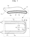
- FIG. 1 is a sectional view of the metal ring according to the first embodiment.
- FIG. 2 is a sectional view of a belt-type continuously variable transmission to which the metal ring according to the first embodiment is applied.
- FIG. 3 is a side view of the belt-type continuously variable transmission to which the metal ring according to the first embodiment is applied.
- the metal ring 11 according to this embodiment is a belt-like member made from a sheet metal. As shown in an upper side of FIG. 1 , the metal ring 11 has nitrided layers 12 in surfaces, namely, an outer peripheral surface 11a, an inner peripheral surface 11b, and both end surfaces 11c, in its section. In other words, an outer edge of a non-nitrided part 11d, which is a bulk layer, is entirely surrounded by the nitrided layers 12.
- the metal ring 11 is curved gently so that a center part of the metal ring 11 in a width direction projects slightly to the outer peripheral surface 11a side from both end parts in the width direction.
- the nitrided layers 12 include first nitrided layers 12a, 12b, which are formed in the outer peripheral surface 11a and the inner peripheral surface 11b of the metal ring 11, respectively, and second nitrided layers 12c formed in both end surfaces 11c of the metal ring 11.
- a thickness Pc of the second nitrided layer 12c is smaller than thicknesses Pa, Pb of the first nitrided layers 12a, 12b. Since the second nitrided layers 12c of the end parts are thin, it is possible to restrain an increase in residual tensile stress in the non-nitrided part 11d on inner sides of the second nitrided layers 12c, thereby restraining fatigue fracture starting from the end parts. It is possible to measure the thicknesses Pa to Pc of the nitrided layers by microstructure observation after Nital etching.
- surface hardness of the end surfaces 11c, in which the second nitrided layers 12c are formed is higher than surface hardness of the main surfaces (the outer peripheral surface 11a and the inner peripheral surface 11b), in which the first nitrided layers 12a, 12b are formed.
- the surface hardness can be measured by, for example, Micro Vickers hardness testing.
- the thickness Pc of the second nitrided layer 12c is smaller than the thicknesses Pa, Pb of the first nitrided layers 12a, 12b, surface hardness of the end surface 11c is higher than surface hardness of the outer peripheral surface 11a and the inner peripheral surface 11b, and the reason is described later.
- the thickness Pc of the second nitrided layer 12c is smaller than the thicknesses Pa, Pb of the first nitrided layers 12a, 12b, and the surface hardness of the end surfaces 11c is higher than the surface hardness of the outer peripheral surface 11a and the inner peripheral surface 11b.
- the second nitrided layers 12c of the end parts are thin, the surface hardness of the end surfaces 11c is large, and it is thus possible to restrain fatigue fracture starting from the end parts, and it is also possible to restrain deterioration of abrasion resistance of the end surfaces 11c.
- the nitrided layer 12 has four chamfered parts in which surfaces are curved between the second nitrided layers 12c and the first nitrided layers 12a, 12b, respectively, and, in the chamfered parts, the thicknesses Pc of the second nitrided layers 12c become larger towards the first nitrided layers 12a, 12b. Further, a radius of curvature of a surface of each of the chamfered parts of the metal ring 11 is larger than the thicknesses Pa to Pc of the nitrided layers.
- the metal ring 11 is made from, for example, maraging steel.
- Maraging steel is precipitation strengthened ultra high strength steel, in which Ni (nickel), Co (cobalt), Mo (molybdenum), Ti (titanium), Al (aluminum), and so on are added with a carbon concentration of 0.03 percent by mass or lower, and high strength and toughness are obtained by aging treatment.
- a composition of maraging steel is not particularly limited, but contains, for example, about 18 percent by mass of Ni, about 10 percent by mass of Co, about 5 percent by mass of Mo, and about 1 percent by mass in total of Ti and Al.
- maraging steel which structures the metal ring 11 according to this embodiment, further contains nitrogen-affinitive metal that does not precipitate during aging treatment.
- the nitrogen-affinitive metal is a metallic element that has a higher chemical affinity with nitrogen than Fe (iron).
- As the nitrogen-affinitive metal Ti, Al, Cr (chrome), and so on may be included. Among them, Ti and Al precipitate during aging treatment, and Cr does not precipitate during aging treatment. Therefore, it is preferred that the metal ring 11 according to this embodiment is made from maraging steel containing Cr.
- a concentration of Cr is preferably between 0.5 ⁇ 1.5 percent by mass.
- the nitrogen-affinitive metal which does not precipitate during aging treatment, works as a trap site for nitrogen atoms during nitriding in the following process.
- a concentration of such nitrogen-affinitive metal in a surface layer of the end surface 11c is higher than a concentration of the nitrogen-affinitive metal in surface layers of the main surfaces, namely, the outer peripheral surface 11a and the inner peripheral surface 11b.
- the concentration of the nitrogen-affinitive metal is high in the surface layer of the end surface 11c, many nitrogen atoms are trapped, thereby achieving thin and hard the second nitrided layer 12c.
- the concentration of the nitrogen-affinitive metal is low, nitrogen atoms enter inside easily, thereby enabling the first nitrided layers 12a, 12b to have a larger thickness and smaller hardness than the second nitrided layer 12c.
- the thickness Pc of the second nitrided layer 12c is made smaller than the thicknesses Pa, Pb of the first nitrided layers 12a, 12b, it is possible to make surface hardness of the end surface 11c higher than surface hardness of the outer peripheral surface 11a and the inner peripheral surface 11b. In short, it is possible to give the end surface 11c high surface hardness even through the second nitrided layer 12c of the end part is thin. Therefore, it is possible to restrain fatigue fracture starting from the end part, and also restrain deterioration of abrasion resistance of the end surface 11c.
- a belt-type continuously variable transmission 1 to which the metal ring 11 according to this embodiment is applied, is explained.
- a plurality of (for example about ten) metal rings 11 having slightly different circumferences from each other are laminated in a nested state, thereby structuring a pair of left and right metal ring laminates 10L, 10R.
- a number of (for example, about 400) elements 15 are lined up without spaces between them and attached to the pair of metal ring laminates 10L, 10R, thereby structuring a transmission belt 2.
- a plate thickness direction of the elements 15 coincides with a circumferential direction of the metal ring laminates 10L, 10R.
- the element 15 is structured from a body 15d, a head 15f, and a neck 15g that connects the body 15d and the head 15f with each other in a center part in the width direction.
- the body 15d has end surface parts 15a, 15b engaged with an input side pulley 4 and an output side pulley 5, and a locking edge part 15c.
- a projecting and recessed engagement part 15e is formed, which is engaged with each other through projections and recesses in the lamination direction.
- the pair of metal ring laminates 10L, 10R are inserted between the body 15d and the head 15f.
- the transmission belt 2 made from the metal ring laminates 10L, 10R and a number of elements 15 is wound around the input side pulley 4 and the output side pulley 5.
- the elements 15 are pressed against the input side pulley 4 and the output side pulley 5 due to tension of the metal ring laminates 10L, 10R. Therefore, it is possible to transmit power from the input side pulley 4 to the output side pulley 5.
- the belt-type continuously variable transmission 1 includes the input side pulley 4 connected with an input shaft 3, the output side pulley 5 connected with an output shaft 6, and the transmission belt 2 for power transmission, which is wound around the input side pulley 4 and the output side pulley 5.
- power is inputted into the input shaft 3 through a clutch and a torque converter from an engine of a vehicle (not shown). Meanwhile, power is outputted to left and right driving wheels through a reduction gear mechanism and a differential gear unit (not shown) from the output shaft 6.
- the output side pulley 5 has a fixed-side sheave member 5a fixed to the output shaft 6, and a movable-side sheave member 5b supported by the output shaft 6 to be able to be displaced in an axial direction.
- a generally V-shaped groove is formed between the fixed-side sheave member 5a and the movable-side sheave member 5b, and a groove width W can be changed.
- a compression coil spring 7 and a hydraulic actuator 8 are attached to the output side pulley 5. The compression coil spring 7 biases the movable-side sheave member 5b in a downshift direction in which the groove width W of the output side pulley 5 is reduced.
- the hydraulic actuator 8 applies hydraulic pressure on a back surface side of the movable-side sheave member 5b, thus displacing the movable-side sheave member 5b in the axis direction.
- the input side pulley 4 has a structure that is generally the same as that of the output side pulley 5 except the fact a biasing member like the compression coil spring 7 is not provided.
- the input side pulley 4 has a fixed-side sheave member fixed to the input shaft 3, and a movable-side sheave member that is supported by the input shaft 3 so as to be able to be displaced in an axis direction and form a generally V-shaped groove between the movable-side sheave member and the fixed-side sheave member.
- the input side pulley 4 has a hydraulic actuator that is able to bias the movable-side sheave member in an upshift direction.
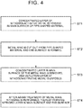
- FIG. 4 is a flowchart showing the manufacturing method for the metal ring according to the first embodiment.
- FIG. 5 is a perspective view showing the manufacturing method for the metal ring according to the first embodiment.
- a concentrated layer having a higher concentration of the nitrogen-affinitive metal than that of the bulk layer is formed in the main surface (the outer peripheral surface and the inner peripheral surface) of the pipe-shaped material, which is a material for the metal ring (step ST1).
- the concentrated layer of the nitrogen-affinitive metal by performing annealing in a reduced-pressure atmosphere or a non-oxidizing atmosphere such as an inert gas atmosphere of nitrogen gas or argon gas at temperature around 820 ⁇ 900 °C for about 60 minutes.
- the concentrated layer is removed, it is preferred that the concentrated layer is about 2 ⁇ m or smaller.
- the nitrogen-affinitive metal is also oxygen-affinitive metal. Therefore, by performing annealing in a non-oxidizing atmosphere, nitrogen-affinitive metal inside the pipe-shaped material is diffused towards a surface on which oxygen is absorbed. Thus, it is possible to form a concentrated layer of the nitrogen-affinitive metal in the main surface (the outer peripheral surface and the inner peripheral surface) of the pipe-shaped material. At the same time, along with formation of the concentrated layer, a depletion layer is formed on an inner side of the concentrated layer. In the depletion layer, a concentration of the nitrogen-affinitive metal is lower than that of the bulk layer.
- an atmosphere for annealing is managed based on understanding of partial pressure of oxygen and a dew point with which a desired concentrated layer is formed.
- annealing is performed in an atmosphere which is obtained by adding hydrogen gas of about 1 to 3 volume percentage to a nitrogen gas, with a dew point of about -10 ⁇ 0 °C.
- the pipe-shaped material As shown in an upper side of FIG. 5 , it is possible to manufacture the pipe-shaped material easily by welding end surfaces of a sheet-shaped material to each other. Annealing in step ST1 also has an effect of homogenizing a welded part.
- the pipe-shaped material is not limited to such a welded pipe and may also be a seamless pipe.
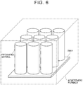
- FIG. 6 is a perspective view schematically showing how annealing of the pipe-shaped materials is performed inside an atmosphere furnace. As shown in FIG. 6 , it is preferred that the pipe-shaped materials are aligned in an erected state at about equal intervals on a tray, and the annealing is performed inside an atmosphere furnace.
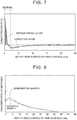
- FIG. 7 is a graph showing a result of depth profiling of Cr by using a glow discharge emission spectrophotometer, in a sample in which a concentrated layer of Cr, which is the nitrogen-affinitive metal, is formed.
- the sample is made from maraging steel to which Cr of 1 percent by mass is added as the nitrogen-affinitive metal.
- annealing was performed at 880 °C for 60 minutes.
- the dew point was adjusted to -5 °C by mixing nitrogen gas with a dew point of +10 °C into nitrogen gas with a dew point of -40 °C.
- a concentrated layer with a depth (thickness) of 1 ⁇ 2 ⁇ m is formed.
- a depletion layer with a depth (thickness) of about 10 ⁇ m is formed on an inner side of the concentrated layer.
- step ST2 the metal rings 11 are cut out from the pipe-shaped material, and the end surfaces 11c are formed (step ST2).
- the bulk layer is exposed on the end surfaces 11c.
- the concentrated layer is formed by step ST1 near surfaces of the outer peripheral surface 11a and the inner peripheral surface 11b, which are the main surfaces of the metal ring 11.
- the bulk layer is exposed on the end surfaces 11c obtained by step ST2 after step ST1, and the concentrated layer and the depletion layer on the inner side of the concentrated layer are not formed near the surfaces of the end surfaces 11c.
- the bulk layer may be exposed on the end surfaces in other way than cutting.
- the bulk layer may be exposed on the end surfaces 11c by polishing the end surfaces 11c and so on.
- the concentrated layer of the nitrogen-affinitive metal which is formed in the outer peripheral surface 11a and the inner peripheral surface 11b that are the main surfaces of the metal ring 11, is removed, thereby exposing the depletion layer of the nitrogen-affinitive metal (step ST3).
- a concentration of the nitrogen-affinitive metal near the surface layers of the end surfaces 11c, where the bulk layer is exposed becomes higher than the concentration of the nitrogen-affinitive metal near the surface layers of the main surfaces, namely, the outer peripheral surface 11a and the inner peripheral surface 11b.
- step ST2 it is possible to remove the concentrated layer by barrel polishing. Burrs caused by cutting in step ST2 can also be removed by barrel polishing. The chamfered parts at four corners are also formed by barrel polishing.
- a method for removing the concentrated layer is not limited to barrel polishing, and may be grindstone polishing and brushing.
- a method for removing the concentrated layer is not limited to a mechanical removal method such as polishing, and may also be a chemical removal method such as etching.
- the order of step ST3 and step ST2 may be switched.
- the concentrated layer was removed by approximately 2 ⁇ m from the surfaces by barrel polishing. This made it possible to expose the depletion layer.
- step ST4 nitriding is performed (step ST4).
- the first nitrided layers 12a, 12b are formed in the outer peripheral surface 11a and the inner peripheral surface 11b of the metal ring 11, and the second nitrided layers 12c are formed in both end surfaces 11c.
- the concentration of the nitrogen-affinitive metal in the surface layers of the end surfaces 11c is higher than the concentration of the nitrogen-affinitive metal in the surface layers of the main surfaces, namely, the outer peripheral surface 11a and the inner peripheral surface 11b. Therefore, in the nitriding in step ST4, a lot of nitrogen atoms are trapped by the nitrogen-affinitive metal near the surface layers of the end surfaces 11c, thereby achieving the thin and hard second nitrided layers 12c. At the same time, nitrogen atoms enter inside easily near the surface layers of the outer peripheral surface 11a and the inner peripheral surface 11b. Thus, the first nitrided layers 12a, 12b, which have larger thicknesses and smaller hardness than the second nitrided layers 12c, are obtained.
- the metal ring 11 it is possible to make surface hardness of the end surfaces 11c higher than surface hardness of the outer peripheral surface 11a and the inner peripheral surface 11b, while making the thicknesses Pc of the second nitrided layers 12c smaller than the thicknesses Pa, Pb of the first nitrided layers 12a, 12b.
- aging treatment is performed, for example, in a nitrogen atmosphere or a reducing atmosphere at temperature of about 450 ⁇ 500 °C for about 90 ⁇ 180 minutes. It is preferred that nitriding is performed in an atmosphere made from 5 ⁇ 15 volume percentage of ammonia gas, 1 ⁇ 3 volume percentage of hydrogen gas, and the remainder nitrogen gas, at temperature of about 400 ⁇ 450 °C for about 40 ⁇ 120 minutes. Hydrogen gas in the atmosphere is generated by thermal decomposition of ammonia gas.
- metal ring 11 is rolled after step ST3 in order to reduce the thickness of the metal ring 11 to a given thickness and to be extended to a given circumference. Thereafter, in order to remove a strain, it is preferred that annealing of the metal ring 11 is performed in a nitrogen atmosphere or a reducing atmosphere at temperature of about 800 ⁇ 900 °C for about 5 ⁇ 30 minutes. Further, it is preferred that tension is applied to the annealed metal ring 11 to adjust the circumference to obtain the given circumference with high accuracy before performing aging treatment in step ST4.
- FIG. 8 is a graph showing results of depth profiling of nitrogen by a glow discharge emission spectrophotometer, in the outer peripheral surfaces 11a of samples after aging treatment.
- An inventive sample shown in FIG. 8 is maraging steel to which 1 percent by mass of Cr is added as the foregoing nitrogen-affinitive metal.
- a comparative sample shown in FIG. 8 is maraging steel that does not contain Cr. The rest of the conditions is the same.
- annealing was also performed for the comparative sample under the same conditions as those of the annealing for forming the aforementioned concentrated layer of Cr. Since the comparative sample does not contain Cr, the concentrated layer of Cr is not formed in the comparative sample as a matter of course.
- Table 1 collectively shows surface hardness and thicknesses of nitrided layers of the outer peripheral surfaces 11a, and surface hardness and thicknesses of nitrided layers of the end surfaces 11c in the comparative sample and the inventive sample.
- Surface hardness was measured by Micro Vickers hardness testing.
- a nitriding depth was measured by microstructure observation after Nital etching.
- the thickness of the second nitrided layer 12c of the end surface 11c is larger than the thickness of the first nitrided layer 12a of the outer peripheral surface 11a. Therefore, surface hardness of the end surface 11c is higher than surface hardness of the outer peripheral surface 11a.
- the thickness of the second nitrided layer 12c of the end surface 11c is smaller than the thickness of the first nitrided layer 12a of the outer peripheral surface 11a. Nevertheless, surface hardness of the end surface 11c is higher than surface hardness of the outer peripheral surface 11a, and maintains equal hardness to that of the comparative sample.
- a concentration of Cr in the surface layer of the end surface 11c is higher than a concentration of Cr in the surface layer of the outer peripheral surface 11a. Therefore, in nitriding, more nitrogen atoms are trapped by Cr atoms near the surface layer of the end surface 11c, thereby achieving the thin and hard second nitrided layer 12c. At the same time, since Cr atoms are deficient near the surface layer in the outer peripheral surface 11a, nitrogen atoms enter inside more easily, thereby achieving the first nitrided layer 12a having a larger thickness and smaller hardness than the second nitrided layer 12c.
- FIG. 9 is a graph showing a change of surface hardness of the end surface with respect to a thickness of a nitrided layer of the end surface.
- FIG. 10 is a graph showing a change of the thickness of the nitrided layer with respect to an amount of nitridation.
- the thickness of the nitrided layer and surface hardness are in a generally proportional relationship with each other.
- the thickness of the nitrided layer saturates gradually as the amount of nitridation increases.
- the thickness of the nitrided layer formed in the end surface is smaller than the thickness of the nitrided layer formed in the main surface because a nitriding inhibition film is formed in the end surface before nitriding.
- the thickness of the nitrided layer is reduced by reducing the number of nitrogen atoms that enter from the end surface.
- the metal ring according to this embodiment contains the nitrogen-affinitive metal such as Cr, which traps the nitrogen atoms.
- the thickness of the nitrided layer is reduced by making nitrogen atoms trapped by nitrogen-affinitive metal so as to restrain the nitrogen atoms from entering inside.
- the thickness of the nitrided layer is larger in the comparative example than that of this embodiment according to the invention. Therefore, when comparison is made with the same thickness of the nitrided layer, inclination of thickness change of the nitrided layer with respect to the amount of nitridation becomes smaller in this embodiment according to the invention than that of the comparative example. In short, in this embodiment according to the invention, it is possible to obtain desired thickness of a nitrided layer and surface hardness more stably than the comparative example.
Landscapes
- Chemical & Material Sciences (AREA)
- Engineering & Computer Science (AREA)
- Mechanical Engineering (AREA)
- Materials Engineering (AREA)
- Metallurgy (AREA)
- Organic Chemistry (AREA)
- General Engineering & Computer Science (AREA)
- Chemical Kinetics & Catalysis (AREA)
- Crystallography & Structural Chemistry (AREA)
- Thermal Sciences (AREA)
- Physics & Mathematics (AREA)
- Inorganic Chemistry (AREA)
- Heat Treatment Of Articles (AREA)
- Solid-Phase Diffusion Into Metallic Material Surfaces (AREA)
Claims (7)
- Procédé de fabrication d'une bague métallique (11) pour une courroie de transmission d'une transmission à variation continue du type à courroie, comprenant :la formation d'une couche concentrée dans une surface principale (11a, 11b) d'un matériau de la bague métallique (11), dans laquelle un métal ayant une affinité pour l'azote est concentré dans la couche concentrée ;le retrait de la couche concentrée, ce qui expose ainsi une couche d'appauvrissement sur la surface principale (11a, 11b), dans lequel le métal ayant une affinité pour l'azote est déficient dans la couche d'appauvrissement ;l'exposition d'une couche volumineuse (11d) sur une surface d'extrémité (11c) de la bague métallique (11) après formation de la couche concentrée ; etla nitruration de la bague métallique (11) dans laquelle la couche d'appauvrissement est exposée sur la surface principale (11a, 11b) et la couche volumineuse (11d) est exposée sur la surface d'extrémité (11c).
- Procédé de fabrication selon la revendication 1, comprenant en outre :la mise en oeuvre d'un traitement de vieillissement de la bague métallique (11) dans laquelle la couche d'appauvrissement est exposée sur la surface principale (11a, 11b) et la couche volumineuse (11d) est exposée sur la surface d'extrémité (11c), avant la nitruration,dans lequel la bague métallique (11) contient de l'acier maraging contenant le métal ayant une affinité pour l'azote qui ne précipite pas durant le traitement de vieillissement.
- Procédé de fabrication selon la revendication 1 ou 2, dans lequel Cr est contenu en tant que métal ayant une affinité pour l'azote.
- Procédé de fabrication selon l'une quelconque des revendications 1 à 3, dans lequel la couche concentrée est effectuée par mise en oeuvre d'un recuit dans une atmosphère sous pression réduite ou dans une atmosphère non oxydante.
- Procédé de fabrication selon l'une quelconque des revendications 1 à 4, dans lequel
la couche concentrée est formée dans la surface principale (11a, 11b) d'un matériau en forme de tuyau, et
la couche volumineuse (11d) est exposée par découpage de la bague métallique (11) dans le matériau en forme de tuyau. - Procédé de fabrication selon l'une quelconque des revendications 1 à 5, dans lequel la couche concentrée est retirée par polissage au tonneau.
- Procédé de fabrication selon l'une quelconque des revendications 1 à 6, dans lequel la surface principale (11a, 11b) comprend une surface périphérique extérieure (11a) de la bague métallique (11) et une surface périphérique intérieure (11b) de la bague métallique (11).
Applications Claiming Priority (1)
| Application Number | Priority Date | Filing Date | Title |
|---|---|---|---|
| JP2015077984A JP6202034B2 (ja) | 2015-04-06 | 2015-04-06 | 金属リング及びその製造方法 |
Publications (2)
| Publication Number | Publication Date |
|---|---|
| EP3078755A1 EP3078755A1 (fr) | 2016-10-12 |
| EP3078755B1 true EP3078755B1 (fr) | 2019-05-22 |
Family
ID=55752164
Family Applications (1)
| Application Number | Title | Priority Date | Filing Date |
|---|---|---|---|
| EP16163796.2A Active EP3078755B1 (fr) | 2015-04-06 | 2016-04-05 | Procédé de fabrication d'un anneau métallique pour courroie de transmission à variation continue |
Country Status (5)
| Country | Link |
|---|---|
| US (1) | US10634216B2 (fr) |
| EP (1) | EP3078755B1 (fr) |
| JP (1) | JP6202034B2 (fr) |
| KR (1) | KR101871039B1 (fr) |
| CN (1) | CN106051046B (fr) |
Families Citing this family (8)
| Publication number | Priority date | Publication date | Assignee | Title |
|---|---|---|---|---|
| JP6113388B1 (ja) * | 2015-08-20 | 2017-04-12 | ユニプレス株式会社 | ベルト式無段変速機に用いるプランジャ部材 |
| WO2019065753A1 (fr) * | 2017-09-28 | 2019-04-04 | Ntn株式会社 | Roulement à rouleaux coniques |
| JP2019189927A (ja) * | 2018-04-27 | 2019-10-31 | トヨタ自動車株式会社 | 無端金属リング、及びその製造方法 |
| JP2019196830A (ja) * | 2018-05-11 | 2019-11-14 | トヨタ自動車株式会社 | 無端金属ベルト、及びその製造方法 |
| WO2021029014A1 (fr) * | 2019-08-13 | 2021-02-18 | 日産自動車株式会社 | Tôle d'acier électromagnétique |
| CA3105667A1 (fr) | 2020-01-15 | 2021-07-15 | Polaris Industries Inc. | Groupe propulseur pour un vehicule utilitaire |
| JP2021127477A (ja) | 2020-02-12 | 2021-09-02 | トヨタ自動車株式会社 | 金属リング積層体の製造方法 |
| CN115306580B (zh) * | 2022-08-29 | 2024-03-01 | 奇瑞汽车股份有限公司 | 一种提升发动机油环刮片质量的方法 |
Family Cites Families (22)
| Publication number | Priority date | Publication date | Assignee | Title |
|---|---|---|---|---|
| JPS6118511A (ja) * | 1984-07-05 | 1986-01-27 | Mazda Motor Corp | 車両の車高調整装置 |
| JPH0641780B2 (ja) | 1985-05-18 | 1994-06-01 | 本田技研工業株式会社 | 無端金属帯板の表面処理方法 |
| JPS61266844A (ja) * | 1985-05-18 | 1986-11-26 | Honda Motor Co Ltd | トルク伝導装置用積層金属ベルト |
| JP3186678B2 (ja) * | 1997-12-10 | 2001-07-11 | 日産自動車株式会社 | ベルト式無段変速機用金属帯の製造方法 |
| EP1094121B1 (fr) * | 1999-10-22 | 2010-06-02 | Honda Giken Kogyo Kabushiki Kaisha | Procédé de fabrication d'un anneau laminé |
| JP4427772B2 (ja) * | 1999-12-24 | 2010-03-10 | 日立金属株式会社 | 高疲労強度を有するマルエージング鋼ならびにそれを用いたマルエージング鋼帯 |
| JP4507149B2 (ja) * | 1999-12-24 | 2010-07-21 | 日立金属株式会社 | 高疲労強度を有する動力伝達ベルト用マルエージング鋼ならびにそれを用いた動力伝達ベルト用マルエージング鋼帯 |
| JP3986996B2 (ja) * | 2003-04-15 | 2007-10-03 | 本田技研工業株式会社 | 金属リングの窒化処理方法 |
| US20050247375A1 (en) * | 2002-09-24 | 2005-11-10 | Teiji Suzuki | Method of nitriding metal ring and apparatus therefor |
| JP3871211B2 (ja) * | 2002-11-14 | 2007-01-24 | トヨタ自動車株式会社 | 無端金属ベルトの製造方法およびその製造装置 |
| JP4511913B2 (ja) * | 2004-12-08 | 2010-07-28 | 本田技研工業株式会社 | 金属ベルト用金属リングの自由状態径設定方法 |
| JP2007154305A (ja) | 2005-07-05 | 2007-06-21 | Jfe Steel Kk | 強度、延性及び靱性に優れた機械構造用鋼およびその製造方法 |
| JP5046363B2 (ja) * | 2005-12-13 | 2012-10-10 | 日立金属株式会社 | 高疲労強度を有する動力伝達用ベルト用マルエージング鋼ならびにそれを用いた動力伝達用ベルト用マルエージング鋼帯 |
| DE102006031348A1 (de) | 2006-07-06 | 2008-01-10 | Woco Avs Gmbh | Elastisches Einsatzlager |
| JP5053651B2 (ja) * | 2007-01-31 | 2012-10-17 | 日立金属株式会社 | 高疲労強度を有するマルエージング鋼帯の製造方法 |
| KR20120078757A (ko) * | 2007-07-11 | 2012-07-10 | 히타치 긴조쿠 가부시키가이샤 | 마레이징강 및 금속 벨트용 마레이징강 |
| NL1037364C2 (en) * | 2009-10-06 | 2011-04-07 | Bosch Gmbh Robert | Drive belt provided with a laminated set of steel rings. |
| US20120241050A1 (en) | 2009-12-25 | 2012-09-27 | Honda Motor Co., Ltd. | Nitriding process for maraging steel |
| JP5146597B2 (ja) * | 2010-04-28 | 2013-02-20 | トヨタ自動車株式会社 | 金属リングおよびその製造方法 |
| JP2012250266A (ja) * | 2011-06-03 | 2012-12-20 | Toyota Motor Corp | 金属リングの製造方法 |
| WO2013047078A1 (fr) * | 2011-09-30 | 2013-04-04 | 日立金属株式会社 | Acier vieilli thermiquement |
| CN104603499A (zh) * | 2012-08-31 | 2015-05-06 | 丰田自动车株式会社 | 环形金属带的制造方法及环形金属带以及带式无级变速器 |
-
2015
- 2015-04-06 JP JP2015077984A patent/JP6202034B2/ja not_active Expired - Fee Related
-
2016
- 2016-04-01 CN CN201610203262.7A patent/CN106051046B/zh not_active Expired - Fee Related
- 2016-04-01 KR KR1020160039898A patent/KR101871039B1/ko not_active Expired - Fee Related
- 2016-04-05 EP EP16163796.2A patent/EP3078755B1/fr active Active
- 2016-04-06 US US15/092,178 patent/US10634216B2/en not_active Expired - Fee Related
Non-Patent Citations (1)
| Title |
|---|
| None * |
Also Published As
| Publication number | Publication date |
|---|---|
| JP6202034B2 (ja) | 2017-09-27 |
| US20160290437A1 (en) | 2016-10-06 |
| CN106051046A (zh) | 2016-10-26 |
| KR101871039B1 (ko) | 2018-07-19 |
| CN106051046B (zh) | 2018-02-09 |
| JP2016196697A (ja) | 2016-11-24 |
| KR20160119698A (ko) | 2016-10-14 |
| US10634216B2 (en) | 2020-04-28 |
| EP3078755A1 (fr) | 2016-10-12 |
Similar Documents
| Publication | Publication Date | Title |
|---|---|---|
| EP3078755B1 (fr) | Procédé de fabrication d'un anneau métallique pour courroie de transmission à variation continue | |
| EP1176224B1 (fr) | Acier maraging nitruré et procédé pour sa fabrication | |
| US9982749B2 (en) | Method for manufacturing endless metal belt, endless metal belt, and belt-type continuously variable transmission | |
| JP5146597B2 (ja) | 金属リングおよびその製造方法 | |
| EP3374662B1 (fr) | Élément annulaire métallique d'une courroie d'entraînement pour une transmission variable en continu | |
| JP5897975B2 (ja) | ベルト式cvtのプーリー用鋼及びベルト式cvtプーリー | |
| US11473184B2 (en) | Method for manufacturing metal ring laminate | |
| EP3081661A1 (fr) | Élément annulaire pour transmission à variation continue et son procédé de production | |
| WO2018122397A1 (fr) | Composant annulaire métallique d'une courroie d'entraînement pour une transmission à variation continue et son procédé de fabrication | |
| CN104728344B (zh) | 无级变速器的传动带及其金属环的制造方法 | |
| JP5701193B2 (ja) | Cvt用リング部材の製造方法およびcvt用リング部材ならびにcvtベルト | |
| EP1514948A1 (fr) | Bande d'acier comprenant de l'acier martensitique et procede de fabrication d'une courroie pour transmission a changement de vitesses continu utilisant une telle bande d'acier | |
| EP3560621A1 (fr) | Anneau en métal sans fin et son procédé de fabrication | |
| EP3569892B1 (fr) | Courroie métallique sans fin et son procédé de fabrication | |
| CN109563907B (zh) | 由马氏体钢制成的并设有氮化表面层的柔性钢制环 | |
| WO2015039933A1 (fr) | Anneau souple en acier pour une courroie d'entraînement pour une transmission variable en continu et son procédé de fabrication | |
| JP2021085529A (ja) | 無段変速機用の駆動ベルトのリングコンポーネント | |
| JP2014177668A (ja) | ベルト式cvt用プーリー及びこのためのプーリー用鋼 | |
| WO2019120627A1 (fr) | Composant annulaire métallique d'une courroie d'entraînement pour une transmission à variation continue et son procédé de fabrication | |
| WO2013081451A1 (fr) | Procédé de traitement thermique dans un procédé de fabrication d'un composant annulaire métallique de courroie d'entraînement |
Legal Events
| Date | Code | Title | Description |
|---|---|---|---|
| PUAI | Public reference made under article 153(3) epc to a published international application that has entered the european phase |
Free format text: ORIGINAL CODE: 0009012 |
|
| 17P | Request for examination filed |
Effective date: 20160405 |
|
| AK | Designated contracting states |
Kind code of ref document: A1 Designated state(s): AL AT BE BG CH CY CZ DE DK EE ES FI FR GB GR HR HU IE IS IT LI LT LU LV MC MK MT NL NO PL PT RO RS SE SI SK SM TR |
|
| AX | Request for extension of the european patent |
Extension state: BA ME |
|
| STAA | Information on the status of an ep patent application or granted ep patent |
Free format text: STATUS: EXAMINATION IS IN PROGRESS |
|
| 17Q | First examination report despatched |
Effective date: 20180124 |
|
| GRAP | Despatch of communication of intention to grant a patent |
Free format text: ORIGINAL CODE: EPIDOSNIGR1 |
|
| STAA | Information on the status of an ep patent application or granted ep patent |
Free format text: STATUS: GRANT OF PATENT IS INTENDED |
|
| INTG | Intention to grant announced |
Effective date: 20181030 |
|
| GRAS | Grant fee paid |
Free format text: ORIGINAL CODE: EPIDOSNIGR3 |
|
| GRAA | (expected) grant |
Free format text: ORIGINAL CODE: 0009210 |
|
| STAA | Information on the status of an ep patent application or granted ep patent |
Free format text: STATUS: THE PATENT HAS BEEN GRANTED |
|
| AK | Designated contracting states |
Kind code of ref document: B1 Designated state(s): AL AT BE BG CH CY CZ DE DK EE ES FI FR GB GR HR HU IE IS IT LI LT LU LV MC MK MT NL NO PL PT RO RS SE SI SK SM TR |
|
| REG | Reference to a national code |
Ref country code: GB Ref legal event code: FG4D |
|
| REG | Reference to a national code |
Ref country code: CH Ref legal event code: EP |
|
| REG | Reference to a national code |
Ref country code: IE Ref legal event code: FG4D |
|
| REG | Reference to a national code |
Ref country code: DE Ref legal event code: R096 Ref document number: 602016014169 Country of ref document: DE |
|
| REG | Reference to a national code |
Ref country code: AT Ref legal event code: REF Ref document number: 1136170 Country of ref document: AT Kind code of ref document: T Effective date: 20190615 |
|
| REG | Reference to a national code |
Ref country code: NL Ref legal event code: FP Ref country code: DE Ref legal event code: R084 Ref document number: 602016014169 Country of ref document: DE |
|
| REG | Reference to a national code |
Ref country code: GB Ref legal event code: 746 Effective date: 20190716 |
|
| REG | Reference to a national code |
Ref country code: LT Ref legal event code: MG4D |
|
| PG25 | Lapsed in a contracting state [announced via postgrant information from national office to epo] |
Ref country code: NO Free format text: LAPSE BECAUSE OF FAILURE TO SUBMIT A TRANSLATION OF THE DESCRIPTION OR TO PAY THE FEE WITHIN THE PRESCRIBED TIME-LIMIT Effective date: 20190822 Ref country code: FI Free format text: LAPSE BECAUSE OF FAILURE TO SUBMIT A TRANSLATION OF THE DESCRIPTION OR TO PAY THE FEE WITHIN THE PRESCRIBED TIME-LIMIT Effective date: 20190522 Ref country code: PT Free format text: LAPSE BECAUSE OF FAILURE TO SUBMIT A TRANSLATION OF THE DESCRIPTION OR TO PAY THE FEE WITHIN THE PRESCRIBED TIME-LIMIT Effective date: 20190922 Ref country code: AL Free format text: LAPSE BECAUSE OF FAILURE TO SUBMIT A TRANSLATION OF THE DESCRIPTION OR TO PAY THE FEE WITHIN THE PRESCRIBED TIME-LIMIT Effective date: 20190522 Ref country code: SE Free format text: LAPSE BECAUSE OF FAILURE TO SUBMIT A TRANSLATION OF THE DESCRIPTION OR TO PAY THE FEE WITHIN THE PRESCRIBED TIME-LIMIT Effective date: 20190522 Ref country code: HR Free format text: LAPSE BECAUSE OF FAILURE TO SUBMIT A TRANSLATION OF THE DESCRIPTION OR TO PAY THE FEE WITHIN THE PRESCRIBED TIME-LIMIT Effective date: 20190522 Ref country code: ES Free format text: LAPSE BECAUSE OF FAILURE TO SUBMIT A TRANSLATION OF THE DESCRIPTION OR TO PAY THE FEE WITHIN THE PRESCRIBED TIME-LIMIT Effective date: 20190522 Ref country code: LT Free format text: LAPSE BECAUSE OF FAILURE TO SUBMIT A TRANSLATION OF THE DESCRIPTION OR TO PAY THE FEE WITHIN THE PRESCRIBED TIME-LIMIT Effective date: 20190522 |
|
| PG25 | Lapsed in a contracting state [announced via postgrant information from national office to epo] |
Ref country code: BG Free format text: LAPSE BECAUSE OF FAILURE TO SUBMIT A TRANSLATION OF THE DESCRIPTION OR TO PAY THE FEE WITHIN THE PRESCRIBED TIME-LIMIT Effective date: 20190822 Ref country code: RS Free format text: LAPSE BECAUSE OF FAILURE TO SUBMIT A TRANSLATION OF THE DESCRIPTION OR TO PAY THE FEE WITHIN THE PRESCRIBED TIME-LIMIT Effective date: 20190522 Ref country code: GR Free format text: LAPSE BECAUSE OF FAILURE TO SUBMIT A TRANSLATION OF THE DESCRIPTION OR TO PAY THE FEE WITHIN THE PRESCRIBED TIME-LIMIT Effective date: 20190823 Ref country code: LV Free format text: LAPSE BECAUSE OF FAILURE TO SUBMIT A TRANSLATION OF THE DESCRIPTION OR TO PAY THE FEE WITHIN THE PRESCRIBED TIME-LIMIT Effective date: 20190522 |
|
| REG | Reference to a national code |
Ref country code: AT Ref legal event code: MK05 Ref document number: 1136170 Country of ref document: AT Kind code of ref document: T Effective date: 20190522 |
|
| PG25 | Lapsed in a contracting state [announced via postgrant information from national office to epo] |
Ref country code: SK Free format text: LAPSE BECAUSE OF FAILURE TO SUBMIT A TRANSLATION OF THE DESCRIPTION OR TO PAY THE FEE WITHIN THE PRESCRIBED TIME-LIMIT Effective date: 20190522 Ref country code: RO Free format text: LAPSE BECAUSE OF FAILURE TO SUBMIT A TRANSLATION OF THE DESCRIPTION OR TO PAY THE FEE WITHIN THE PRESCRIBED TIME-LIMIT Effective date: 20190522 Ref country code: CZ Free format text: LAPSE BECAUSE OF FAILURE TO SUBMIT A TRANSLATION OF THE DESCRIPTION OR TO PAY THE FEE WITHIN THE PRESCRIBED TIME-LIMIT Effective date: 20190522 Ref country code: DK Free format text: LAPSE BECAUSE OF FAILURE TO SUBMIT A TRANSLATION OF THE DESCRIPTION OR TO PAY THE FEE WITHIN THE PRESCRIBED TIME-LIMIT Effective date: 20190522 Ref country code: AT Free format text: LAPSE BECAUSE OF FAILURE TO SUBMIT A TRANSLATION OF THE DESCRIPTION OR TO PAY THE FEE WITHIN THE PRESCRIBED TIME-LIMIT Effective date: 20190522 Ref country code: EE Free format text: LAPSE BECAUSE OF FAILURE TO SUBMIT A TRANSLATION OF THE DESCRIPTION OR TO PAY THE FEE WITHIN THE PRESCRIBED TIME-LIMIT Effective date: 20190522 |
|
| REG | Reference to a national code |
Ref country code: DE Ref legal event code: R097 Ref document number: 602016014169 Country of ref document: DE |
|
| PG25 | Lapsed in a contracting state [announced via postgrant information from national office to epo] |
Ref country code: SM Free format text: LAPSE BECAUSE OF FAILURE TO SUBMIT A TRANSLATION OF THE DESCRIPTION OR TO PAY THE FEE WITHIN THE PRESCRIBED TIME-LIMIT Effective date: 20190522 Ref country code: IT Free format text: LAPSE BECAUSE OF FAILURE TO SUBMIT A TRANSLATION OF THE DESCRIPTION OR TO PAY THE FEE WITHIN THE PRESCRIBED TIME-LIMIT Effective date: 20190522 |
|
| PLBE | No opposition filed within time limit |
Free format text: ORIGINAL CODE: 0009261 |
|
| STAA | Information on the status of an ep patent application or granted ep patent |
Free format text: STATUS: NO OPPOSITION FILED WITHIN TIME LIMIT |
|
| PG25 | Lapsed in a contracting state [announced via postgrant information from national office to epo] |
Ref country code: TR Free format text: LAPSE BECAUSE OF FAILURE TO SUBMIT A TRANSLATION OF THE DESCRIPTION OR TO PAY THE FEE WITHIN THE PRESCRIBED TIME-LIMIT Effective date: 20190522 |
|
| 26N | No opposition filed |
Effective date: 20200225 |
|
| PG25 | Lapsed in a contracting state [announced via postgrant information from national office to epo] |
Ref country code: PL Free format text: LAPSE BECAUSE OF FAILURE TO SUBMIT A TRANSLATION OF THE DESCRIPTION OR TO PAY THE FEE WITHIN THE PRESCRIBED TIME-LIMIT Effective date: 20190522 |
|
| PG25 | Lapsed in a contracting state [announced via postgrant information from national office to epo] |
Ref country code: SI Free format text: LAPSE BECAUSE OF FAILURE TO SUBMIT A TRANSLATION OF THE DESCRIPTION OR TO PAY THE FEE WITHIN THE PRESCRIBED TIME-LIMIT Effective date: 20190522 |
|
| PG25 | Lapsed in a contracting state [announced via postgrant information from national office to epo] |
Ref country code: MC Free format text: LAPSE BECAUSE OF FAILURE TO SUBMIT A TRANSLATION OF THE DESCRIPTION OR TO PAY THE FEE WITHIN THE PRESCRIBED TIME-LIMIT Effective date: 20190522 |
|
| REG | Reference to a national code |
Ref country code: CH Ref legal event code: PL |
|
| PG25 | Lapsed in a contracting state [announced via postgrant information from national office to epo] |
Ref country code: CH Free format text: LAPSE BECAUSE OF NON-PAYMENT OF DUE FEES Effective date: 20200430 Ref country code: LI Free format text: LAPSE BECAUSE OF NON-PAYMENT OF DUE FEES Effective date: 20200430 Ref country code: LU Free format text: LAPSE BECAUSE OF NON-PAYMENT OF DUE FEES Effective date: 20200405 |
|
| REG | Reference to a national code |
Ref country code: BE Ref legal event code: MM Effective date: 20200430 |
|
| PG25 | Lapsed in a contracting state [announced via postgrant information from national office to epo] |
Ref country code: BE Free format text: LAPSE BECAUSE OF NON-PAYMENT OF DUE FEES Effective date: 20200430 |
|
| PG25 | Lapsed in a contracting state [announced via postgrant information from national office to epo] |
Ref country code: IE Free format text: LAPSE BECAUSE OF NON-PAYMENT OF DUE FEES Effective date: 20200405 |
|
| PGFP | Annual fee paid to national office [announced via postgrant information from national office to epo] |
Ref country code: GB Payment date: 20220303 Year of fee payment: 7 |
|
| PG25 | Lapsed in a contracting state [announced via postgrant information from national office to epo] |
Ref country code: MT Free format text: LAPSE BECAUSE OF FAILURE TO SUBMIT A TRANSLATION OF THE DESCRIPTION OR TO PAY THE FEE WITHIN THE PRESCRIBED TIME-LIMIT Effective date: 20190522 Ref country code: CY Free format text: LAPSE BECAUSE OF FAILURE TO SUBMIT A TRANSLATION OF THE DESCRIPTION OR TO PAY THE FEE WITHIN THE PRESCRIBED TIME-LIMIT Effective date: 20190522 |
|
| PGFP | Annual fee paid to national office [announced via postgrant information from national office to epo] |
Ref country code: NL Payment date: 20220314 Year of fee payment: 7 Ref country code: FR Payment date: 20220308 Year of fee payment: 7 |
|
| PG25 | Lapsed in a contracting state [announced via postgrant information from national office to epo] |
Ref country code: MK Free format text: LAPSE BECAUSE OF FAILURE TO SUBMIT A TRANSLATION OF THE DESCRIPTION OR TO PAY THE FEE WITHIN THE PRESCRIBED TIME-LIMIT Effective date: 20190522 Ref country code: IS Free format text: LAPSE BECAUSE OF FAILURE TO SUBMIT A TRANSLATION OF THE DESCRIPTION OR TO PAY THE FEE WITHIN THE PRESCRIBED TIME-LIMIT Effective date: 20190922 |
|
| P01 | Opt-out of the competence of the unified patent court (upc) registered |
Effective date: 20230427 |
|
| PGFP | Annual fee paid to national office [announced via postgrant information from national office to epo] |
Ref country code: DE Payment date: 20230228 Year of fee payment: 8 |
|
| REG | Reference to a national code |
Ref country code: NL Ref legal event code: MM Effective date: 20230501 |
|
| GBPC | Gb: european patent ceased through non-payment of renewal fee |
Effective date: 20230405 |
|
| PG25 | Lapsed in a contracting state [announced via postgrant information from national office to epo] |
Ref country code: GB Free format text: LAPSE BECAUSE OF NON-PAYMENT OF DUE FEES Effective date: 20230405 |
|
| PG25 | Lapsed in a contracting state [announced via postgrant information from national office to epo] |
Ref country code: NL Free format text: LAPSE BECAUSE OF NON-PAYMENT OF DUE FEES Effective date: 20230501 Ref country code: GB Free format text: LAPSE BECAUSE OF NON-PAYMENT OF DUE FEES Effective date: 20230405 Ref country code: FR Free format text: LAPSE BECAUSE OF NON-PAYMENT OF DUE FEES Effective date: 20230430 |
|
| REG | Reference to a national code |
Ref country code: DE Ref legal event code: R119 Ref document number: 602016014169 Country of ref document: DE |
|
| PG25 | Lapsed in a contracting state [announced via postgrant information from national office to epo] |
Ref country code: DE Free format text: LAPSE BECAUSE OF NON-PAYMENT OF DUE FEES Effective date: 20241105 |
|
| PG25 | Lapsed in a contracting state [announced via postgrant information from national office to epo] |
Ref country code: DE Free format text: LAPSE BECAUSE OF NON-PAYMENT OF DUE FEES Effective date: 20241105 |