EP3078791B1 - Standflügelschloss, insbesondere panikschloss - Google Patents
Standflügelschloss, insbesondere panikschloss Download PDFInfo
- Publication number
- EP3078791B1 EP3078791B1 EP15001021.3A EP15001021A EP3078791B1 EP 3078791 B1 EP3078791 B1 EP 3078791B1 EP 15001021 A EP15001021 A EP 15001021A EP 3078791 B1 EP3078791 B1 EP 3078791B1
- Authority
- EP
- European Patent Office
- Prior art keywords
- lock
- latch
- ejector
- door opener
- fixed leaf
- Prior art date
- Legal status (The legal status is an assumption and is not a legal conclusion. Google has not performed a legal analysis and makes no representation as to the accuracy of the status listed.)
- Active
Links
Images






Classifications
-
- E—FIXED CONSTRUCTIONS
- E05—LOCKS; KEYS; WINDOW OR DOOR FITTINGS; SAFES
- E05C—BOLTS OR FASTENING DEVICES FOR WINGS, SPECIALLY FOR DOORS OR WINDOWS
- E05C7/00—Fastening devices specially adapted for two wings
- E05C7/04—Fastening devices specially adapted for two wings for wings which abut when closed
-
- E—FIXED CONSTRUCTIONS
- E05—LOCKS; KEYS; WINDOW OR DOOR FITTINGS; SAFES
- E05B—LOCKS; ACCESSORIES THEREFOR; HANDCUFFS
- E05B47/00—Operating or controlling locks or other fastening devices by electric or magnetic means
- E05B47/0046—Electric or magnetic means in the striker or on the frame; Operating or controlling the striker plate
-
- E—FIXED CONSTRUCTIONS
- E05—LOCKS; KEYS; WINDOW OR DOOR FITTINGS; SAFES
- E05B—LOCKS; ACCESSORIES THEREFOR; HANDCUFFS
- E05B63/00—Locks or fastenings with special structural characteristics
- E05B63/24—Arrangements in which the fastening members which engage one another are mounted respectively on the wing and the frame and are both movable, e.g. for release by moving either of them
- E05B63/248—Arrangements in which the fastening members which engage one another are mounted respectively on the wing and the frame and are both movable, e.g. for release by moving either of them the striker being movable for latching, and pushed back by a member on the wing for unlatching, or vice versa
Definitions
- the invention relates to a ball and socket lock, in particular with a panic function, with a lock plate having a latch housing, with a provided in the lock housing lock nut, provided in the lock housing in the latch opening electric door openers and a Fallenauswerfer having a trap ejection device for ejecting a in the trap opening engaging case of a moving wing lock is formed and provided.
- a pothole lock of the type mentioned is already out of the DE 10 2009 061 132 B3 known.
- a pommel lock which is also referred to as a counter-box, interacts with a pigeon lock having a latch and a latch.
- the trap of the active wing lock enters the trap opening of the passive wing lock.
- the moving wing lock usually has a latch and the poppet lock in the forend a latch opening so that the latch of the swing gate lock can enter the latch opening in the forend of the poppet lock.
- the pianoforte lock is otherwise provided with a panic function. Then such a lock is also called a panic lock.
- the poppet lock has a Fallenauswerfer and a Latch ejector to push out both the latch and the latch from the lock housing of the poppet lock can.
- this is done when you press the pusher of the poppet lock, which acts on the lock nut and on this on the lock mechanism and actuates the aforementioned ejector.
- a wing lock which has an electric door opener.
- the electric door opener is located in the lock housing in the area of the latch opening.
- the door opener has a Schwenklade for the case of the moving wing lock.
- the trap ejection device of the known passive leaf lock has a linearly adjustable fall outlet tappet, which is part of the electric door opener and is displaceably mounted in its housing.
- the door opener of the known passive leaf lock is relatively complex due to its design with the door opener and ejector.
- the housing form of the door opener with the rear housing extension requires a special, adapted to the necessary housing shape mounting space in the lock housing. If the door opener is defective and has to be replaced, a door opener with a conventional cuboid door opener housing can not be used.
- Object of the present invention is therefore to avoid the disadvantages of the prior art.
- the aforementioned object is achieved according to the invention substantially in a poppet lock of the type mentioned in that the Fallenauswerfer annoying is independent of the electric door opener and that the Fallenauswerfer is stored outside the electric door opener in the lock housing.
- the invention is a new way compared to the prior art. Unlike the prior art, the Fallenauswerfer is not stored in the door openers, but on the lock housing itself. At most, it still allows the invention that the Fallenauswerfer is mounted on the outside of the lock housing. In any case, the trap ejector is not an integral part of the door opener. The trap ejector device is thus independent of the electric door opener.
- the invention differs from the prior art aspect.
- the in-wing lock according to the invention can thus be equipped, if necessary, with or without an electric door opener.
- the invention has the very significant advantage that a conventional door opener can be used, which must have neither a special form nor corresponding connection means for actuating the Fallenauswerfer issued, as this is completely independent of the door opener.
- the invention thus simplifies the structure of the electric door opener such that such an electric door opener can be used, which is equipped without a trap ejector and at all without a Fallenauswerfer observed total.
- the design of the trap ejector device which is independent of the electric door opener can be realized, in particular, by the fact that the trap ejector is mounted pivotably in the region of the trap opening in the mounting direction in front of the electric door opener.
- the storage of the fall ejector in the mounting direction before the electric door opener means that with the open-winged lock the trap ejector can only be removed when the electric door opener has been dismantled. Accordingly, during assembly, the trap ejector must first be mounted before the electric door opener is mounted.
- the Fallenauswerfer is mounted below or above the electric door opener displaced.
- the information above or below refers to the horizontal state of the pothole lock.
- the Fallenauswerfer is then between the electric door opener and the castle floor or the castle ceiling.
- the trap ejector is not pivotally movable, but displaceable by a reciprocating motion.
- the Fallenauswerfer stored as a forend in the region of the trap opening Swivel lever is formed. Due to the displacement of the fall ejector in the region of the trap opening and by storage of the trap ejector on the forend a very space-saving arrangement of Fallenauswerfers is ensured in the lock housing of the passive lock, regardless of whether the electric door opener is provided in the invention wing hinge lock or not.
- the trap ejector has an ejector shaft extending over the length of the trap opening.
- the shaft is in turn provided at the end with bearing sections which are mounted on the forend in the region of the overlapping short sides of the latch opening.
- the ejector shaft is preferably arranged parallel and immediately adjacent to the one longitudinal edge of the latch opening, so that the major part of the latch opening is released for immersion of the trap of the swing gate lock in the latch opening. It is understood that the ejector shaft should preferably be arranged in the region of the latch opening, in which the latch engages in the engaged state at least far.
- an ejector arm of the trap ejector which spans the trap opening transversely and projects from the ejector shaft.
- the ejector is provided at least in the central region of the ejector, so that a central attack occurs when ejecting the trap.
- an electric door opener which has a pivoting door for receiving the latch of the moving wing lock
- at least one slot is in this case in the region of the pivoting latch provided for dipping the Auswerferarms in the swing door of the door opener. In the unactuated, non-swung out condition of Auswerferarmes this is then swung back in the swing tray in the slot provided so that the immersion of the trap is not affected by the Auswerferarm in the swing tray.
- a bearing part with corresponding storage areas is provided on the inside of the forend.
- bearing receptacles for arranging the bearing sections of the ejector shaft can also be provided on the forend itself.
- corresponding grooves for the bearing sections of the ejector shaft are provided on the inside of the forend.
- a bearing section of the fall ejector is followed by an actuating arm projecting into the lock housing.
- the actuating arm projects approximately at right angles from the shaft axis of the ejector shaft. Since the actuating arm is directly connected to the ejection arm via the ejector shaft, a movement, and in particular an upward movement of the actuating arm, results in a swiveling movement of the ejector arm for ejecting the case of the moving wing lock.
- a freewheeling window for the actuating arm is provided in the bearing part and / or on the inside of the forend.
- the actuating arm in the region of the freewheeling window is not only led out of the bearing part, the freewheeling window is also larger than each of the bearing areas, which is due to the necessary pivotability or movement of the actuating arm.
- the coupled to the actuating arm of the fall ejector actuating means is also pivotally mounted and has a ramp for cooperation with the actuating arm.
- the ramp is preferably in the form of a rising helix. This leads to a pivoting movement of Actuation means that the lying on the ramp beeping arm is moved during a rotational movement of the actuating means along the ramp, which in turn leads to a pivoting movement of the Fallenauswerfers and thus the ejector movement of Auswerferarms.
- the aforementioned, ultimately designed in the form of a worm actuating means acts on actuation of the lock nut with a linear adjustable in the lock housing slider.
- the slider ultimately sets the predetermined by the lock nut rotational movement when pressing the lock in a translational or longitudinal movement.
- an upper bar connection is connected to the coupling with a push rod with the linearly adjustable slide.
- the slide can also be formed integrally with the upper rod connection.
- the actuating means In order to have a defined and coupled movement between the linearly adjustable slider and the actuating means, the actuating means on an engaging portion, which cooperates with an engagement opening on the slider. This is done in such a way that during a linear movement of the slide, which is triggered by a rotational movement of the lock nut, the actuating means is pivoted accordingly. This pivoting movement is then, as has already been stated above, converted into a pivoting movement of the fall ejector, which ultimately leads to the ejection of a possibly dipping into the trap opening case of the moving wing lock.
- the trapdoor is otherwise spring-loaded against the ejector direction.
- a spring is preferably mounted for this purpose, in particular on the inside of the forend, which acts on the actuating arm.
- the spring load results in the result that the operating portion is always pressed onto the ramp.
- the spring load causes the ejector of Fallenauswerfers is always pressed in unconfirmed Fallenauswerfer observed in the swing of any available door opener.
- a wing lock 1 or individual parts thereof are shown.
- the illustrated wing lock 1 has a panic function. It is a panic lock.
- With the grand piano lock 1 acts a not shown in detail a wing hinge lock, of which only a case 2 is shown in different figures.
- the in-wing lock 1 and the moving-wing lock form a cooperating lock arrangement, although in the case of the invention essentially only the fixed-wing lock 1 is involved.
- the example in the Fig. 1 to 3 illustrated case 2 of the moving wing lock is used only to explain the function of the poppet lock. 1
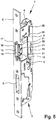
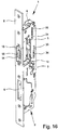
- the grand piano lock 1 has a lock housing 3 with a lock case 4, a lock cover 5 and a forend 6.
- the latch opening 7 is used for immersion of the case 2 of the swing gate lock
- the latch opening 8 is used for immersion of the bolt of the moving wing lock.
- the lock mechanism In the lock housing 3 is the lock mechanism with the central lock nut 9, which is provided with a square opening for inserting the square of outer actuators.
- the lock nut 9 in the present case is a two-piece lock nut.
- an electric door opener 10 is provided in the lock housing 3 in the region of the latch opening 7.
- the door opener 10, which is electrically actuated, has a latch opening 11 open towards the latch opening 7 for receiving the latch 2.
- the pivoting drawer 11 projects into the trap opening 7.
- the latch opening 7 is opened in the region of the pivoting direction of the pivoting drawer. It is therefore not a closed trap opening 7. In the non-energized or otherwise not released state of the swing tray 11, this is in the swung back state, the in Fig. 19 is best shown.
- the mounting space 12 which serves as needed arrangement of the electric door opener 10 has corresponding dimensions to accommodate the electric door opener 10 can.
- the mounting space 12 extends in the longitudinal direction of the lock housing in both directions beyond the latch opening 7 addition.
- the width of the mounting space occupies more than half the width of the lock housing 3.
- a recess 13 for the required arrangement of the electric door opener.
- the recess 13 ultimately represents the base of the mounting space 12.
- the forend 6 is closed in the region of the trap opening 7.
- the trap opening 7 is then an overall closed opening.
- the opposite of the open latch opening provided leg forms the abutment for the case 2, which is formed in the embodiment with the electric door opener 10 of the pivoting plate 11.
- the poppet lock 1 a Fallenauswerfer
- the Fallenauswerfer observed used to eject the, if necessary, in the latch opening 7 engaging case 2 of the moving wing lock.
- the Fallenauswerfer is independent of the electric door opener 10, regardless of whether it is provided or not. In any case, it is so that the Fallenauswerfer 14 is mounted outside of the electric door opener 10 in the lock housing 3.
- the poppet lock 1 is thus designed such that in each case a mounting space 12 is provided for the arrangement of the electric door opener 10 in the lock housing 3 and the mounting space 12 for the electric door opener remains free even if the electric door opener is not provided, such as this in the embodiments of Fig. 9 to 16 and 25 to 32 the case is.
- the Fallenauswerfer worn 14 of the Fallenauswerfer is mounted in front of the electric door opener 10 pivotally mounted in the region of the latch opening 7.
- the Fallenauswerfer 14 is in front of the electric door opener 10, regardless of whether individual parts of the electric door opener 10 possibly survive on the Fallenauswerfer 14.
- the Fallenauswerfer 14 is based on the forend 6 in front of the door opener housing 15th
- the fall ejector based on the in Fig. 1 illustrated state or in a horizontal arrangement of the castle is arranged above or below the electric door opener.
- the trap ejector could thereby connect to the upper or lower wall of the door opener housing.
- the Fallenauswerfer is actuated from its rear end, so that there is a longitudinal displacement of the Fallenauswerfers in the direction of the case 2, that is, from the latch opening 7 out.
- the trap ejector 14 is designed as a swivel lever mounted on the forend 6 on the inside in the region of the latch opening 7.
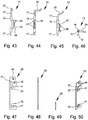
- the specific embodiment of the designed as a pivot lever Fallenauswerfers 14 results from the FIGS. 43 to 46 ,
- the Fallenauswerfer 14 has an over the length of the latch opening 7 extending ejector 16 with each end provided bearing portions 17 for pivotal mounting.
- the ejector shaft 16 is arranged parallel and immediately adjacent to the one longitudinal edge 18 of the latch opening 7. Finally, the ejector shaft 16 spans the latch opening 7 in its longitudinal direction.
- the ejector shaft 16 has, in particular in its central region, an ejector arm 19 which extends in the present case approximately in the radial direction and runs transversely to the latch opening 7.
- the Auswerferarm 19 is used to eject the case 2 when pivoting the Fallenauswerfers 4.
- the Auswerferarm 19 ends two projections 20 which dive into corresponding slots 21 of the swing tray 11. This makes it possible that the Auswerferarm 19 of the Fallenauswerfers 14 in the pivoted state does not affect a dipping into the swing tray 11 trap.
- a bearing part 22 with bearing areas 23 for the bearing portions 17 of the ejector shaft 16 is fastened.
- Corresponding to the bearing portions 23 are formed on the inside of the forend 6 formed as grooves bearing receivers 24 for the arrangement of the bearing portions 17.
- the bearing areas 23 on the bearing parts 22 are ultimately slots or recesses in the bearing part 22 which, together with the grooved bearing receivers 24, completely absorb the bearing sections 17 of the ejector shaft in terms of their thickness. This means that the thickness of the bearing part 22 including the groove depth of the bearing mounts 24 corresponds to the diameter of the bearing portions 17 at least substantially or is slightly larger.
- the front end face of the door opener housing 15 of the electric door opener 10 at least partially, but in any case in the area of the bearing areas 23 against the bearing part 22 is arranged. In this way it is prevented that the Fallenauswerfer 14 can get out of its storage position in the storage areas 23 and bearing receivers 24, while maintaining its pivoting mobility at the same time.
- the bearing part can either have the same shape, which in the FIGS. 47 to 50 is shown, in which case, however, an outer end or a corresponding means for arrangement in the region of the bearing areas 23 is required in order to prevent the bearing sections 17 from falling out of the bearing areas 23 or the bearing seats 24.
- FIGS. 43 to 46 results in one of the bearing portions 17 of the Fallenauswerfers 14 an actuating arm 25, which projects into the interior of the lock housing 3.
- the actuating arm 25 is provided for cooperation with an actuating means 26, which is also arranged in the lock housing 3.
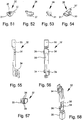
- the actuating means 26 as such is in the FIGS. 51 to 54 shown.
- a freewheeling window 27 is provided in the bearing part 22.
- a corresponding freewheeling window 28 is provided on the inside of the forend following one of the bearing receptacles 24.
- the freewheeling windows 27, 28 allow movement of the one of the bearing portion 17 of the Fallenauswerfers 14 bent actuator arm 25th
- actuating means 26 is pivotally mounted in the lock housing 3.
- a corresponding bearing pin 29 is provided on the lock housing, to which the actuating means 26 via a corresponding bearing opening 30 is placed.
- the actuating means 26 has a particular winding bevel 31, which is formed in the manner of a worm gear.
- the free end of the actuating arm 25 rests on the ramp 31.
- the free end of the actuating arm 25 moves along the ramp 30 and is raised or lowered, so that a pivoting movement of the Fallenauswerfers 14 results.
- the rotary or pivoting movement of the actuating means 26 takes place by cooperation with a slider 32 which in the FIGS. 55 to 58 is shown.
- the slider 32 is linearly displaceable in the lock housing 3 and in turn interacts with the lock nut 9.
- a rotational movement of the lock nut 9 leads to a linear movement of the slider 32, which in turn leads to a rotational or pivoting movement of the actuating means 26.
- the slide 32 may in principle be a transmission means in order to transmit the movement of the lock nut 9 to the actuating means 26.
- an upper bar connection 33 is integrally formed with the slide 32 for connection to a push rod (not shown).
- a push rod for guidance in the linear movement of the slide 32, this has on opposite sides corresponding guide projections 34 which engage in corresponding slots 35 at the bottom of the lock case 4 and in the lock cover 5.
- the slider 32 has an engagement opening 36 which is provided for engagement of a corresponding engagement portion 37 of the actuating means 26.
- the Fallenauswerfer 14 is spring-loaded against the ejector.
- a spring element 38 acts on the actuating arm 25 of the Fallenauswerfers 14.
- the spring element 38 is mounted on a bearing 39 on the bearing part 22.
- two openings 40 are provided on the bearing part 22, which serve to hold the bearing 39.
- the bearing part 22 has two further openings 41, which serve for fastening of the bearing part 22 and also of the electric door opener 10.
- Fig. 17 shows a state in which the trap 2 is immersed in the pivoting blade 11 of the door opener 10.
- the Fallenauswerfer 14 is pivoted back, wherein the free end of the actuating arm 25 is arranged at the lower end of the ramp 31.
- the lock nut 9 is in the unactuated state.
Landscapes
- Engineering & Computer Science (AREA)
- Mechanical Engineering (AREA)
- Physics & Mathematics (AREA)
- Electromagnetism (AREA)
- Structural Engineering (AREA)
- Lock And Its Accessories (AREA)
Priority Applications (2)
| Application Number | Priority Date | Filing Date | Title |
|---|---|---|---|
| EP15001021.3A EP3078791B1 (de) | 2015-04-10 | 2015-04-10 | Standflügelschloss, insbesondere panikschloss |
| PL15001021T PL3078791T3 (pl) | 2015-04-10 | 2015-04-10 | Zamek do skrzydła biernego, zwłaszcza zamek antypaniczny |
Applications Claiming Priority (1)
| Application Number | Priority Date | Filing Date | Title |
|---|---|---|---|
| EP15001021.3A EP3078791B1 (de) | 2015-04-10 | 2015-04-10 | Standflügelschloss, insbesondere panikschloss |
Publications (2)
| Publication Number | Publication Date |
|---|---|
| EP3078791A1 EP3078791A1 (de) | 2016-10-12 |
| EP3078791B1 true EP3078791B1 (de) | 2017-06-21 |
Family
ID=52874919
Family Applications (1)
| Application Number | Title | Priority Date | Filing Date |
|---|---|---|---|
| EP15001021.3A Active EP3078791B1 (de) | 2015-04-10 | 2015-04-10 | Standflügelschloss, insbesondere panikschloss |
Country Status (2)
| Country | Link |
|---|---|
| EP (1) | EP3078791B1 (pl) |
| PL (1) | PL3078791T3 (pl) |
Cited By (1)
| Publication number | Priority date | Publication date | Assignee | Title |
|---|---|---|---|---|
| WO2019077632A1 (en) * | 2017-10-17 | 2019-04-25 | Deepak Pathania | INTELLIGENT LOCKING CONVERTER |
Family Cites Families (7)
| Publication number | Priority date | Publication date | Assignee | Title |
|---|---|---|---|---|
| DE102004009973B4 (de) * | 2004-03-01 | 2007-03-22 | Wilh. Schlechtendahl & Söhne GmbH & Co KG | Gegenkasten für ein Paniktürschloß |
| DE102005015248B4 (de) * | 2005-04-02 | 2010-01-21 | Wilka Schließtechnik GmbH | Standflügelschloss mit einem elektrischen Türöffner |
| DE102006038625B3 (de) * | 2006-08-17 | 2007-10-25 | Wilh. Schlechtendahl & Söhne GmbH & Co. KG | Schlanker Gegenkasten für ein Paniktürschloss |
| DE102006038610B4 (de) * | 2006-08-17 | 2008-07-17 | Wilh. Schlechtendahl & Söhne GmbH & Co. KG | Schlanker Gegenkasten für ein Paniktürschloss |
| DE102009043962B4 (de) * | 2009-09-09 | 2012-08-09 | Wilka Schließtechnik GmbH | Elektrischer Türöffner |
| DE102009061132B3 (de) | 2009-09-09 | 2014-03-27 | Wilka Schließtechnik GmbH | Standflügelschloss mit elektrischem Türöffner |
| DE102012111881B4 (de) * | 2012-12-06 | 2021-12-30 | WILKA Schließtechnik GmbH | Motorisch betreibbares Standflügelschloss mit Riegel- und Fallenauswerfer |
-
2015
- 2015-04-10 EP EP15001021.3A patent/EP3078791B1/de active Active
- 2015-04-10 PL PL15001021T patent/PL3078791T3/pl unknown
Non-Patent Citations (1)
| Title |
|---|
| None * |
Cited By (1)
| Publication number | Priority date | Publication date | Assignee | Title |
|---|---|---|---|---|
| WO2019077632A1 (en) * | 2017-10-17 | 2019-04-25 | Deepak Pathania | INTELLIGENT LOCKING CONVERTER |
Also Published As
| Publication number | Publication date |
|---|---|
| PL3078791T3 (pl) | 2017-11-30 |
| EP3078791A1 (de) | 2016-10-12 |
Similar Documents
| Publication | Publication Date | Title |
|---|---|---|
| EP3267837B1 (de) | Befestigungsvorrichtung zum lösbaren befestigen einer frontblende an einer schublade | |
| EP3133232B1 (de) | Vorrichtung zum bewegen eines bewegbaren möbelteils sowie möbel mit einer vorrichtung zum bewegen eines bewegbaren möbelteils | |
| DE102015117415A1 (de) | Türöffner | |
| EP0156379B1 (de) | Kassenlade für eine Registrierkasse | |
| EP3078791B1 (de) | Standflügelschloss, insbesondere panikschloss | |
| EP2754800B1 (de) | Gegenkasten oder Einsteckschloss | |
| DE202008006506U1 (de) | Schnäpper für eine Drehkipptür | |
| DE4125448A1 (de) | Elektromotorischer stellantrieb fuer eine zentrale tuerverriegelungsanlage eines kraftfahrzeugs | |
| DE102015000606A1 (de) | Verriegelungsvorrichtung für einen schwenkbar gelagerten Flügel | |
| EP2754801B1 (de) | Gegenkasten oder Einsteckschloss | |
| EP3162995A1 (de) | Beschlagteil eines beschlages für einen flügel eines fensters oder einer tür | |
| DE69807608T2 (de) | Schliessvorrichtung, insbesondere Einsteckschloss mit einer Falle, für eine Fenstertür oder dergleichen | |
| EP3122969B1 (de) | Riegelstangen/klemmschloss | |
| DE202015000208U1 (de) | Schloss zur Betätigung wenigstens einer Treibstange | |
| EP2882916B1 (de) | Türöffner für eine tür in einem gebäude | |
| EP2559355B1 (de) | Vorrichtung zur Bewegung eines bewegbaren Möbelteils, Führungseinheit und Möbel | |
| DE10357721B4 (de) | Verschlußvorrichtung für Türen oder Fenster | |
| DE102014104101A1 (de) | Schaltschloss für Riegelstange | |
| DE69807801T2 (de) | Verriegelungsvorrichtung, insbesondere Einsteckschloss für den Flügel einer Tür oder eines Fensters | |
| DE102016118110A1 (de) | Verriegelungsvorrichtung für einen schwenkbar gelagerten Flügel | |
| DE202012012085U1 (de) | Schaltschloss | |
| EP2746506B1 (de) | Schaltschloss | |
| EP2674554A2 (de) | Fallenriegelschloss | |
| EP4541989A1 (de) | Schloss mit umwendbarer falle | |
| EP2719850B1 (de) | Einsteckschloss |
Legal Events
| Date | Code | Title | Description |
|---|---|---|---|
| PUAI | Public reference made under article 153(3) epc to a published international application that has entered the european phase |
Free format text: ORIGINAL CODE: 0009012 |
|
| AK | Designated contracting states |
Kind code of ref document: A1 Designated state(s): AL AT BE BG CH CY CZ DE DK EE ES FI FR GB GR HR HU IE IS IT LI LT LU LV MC MK MT NL NO PL PT RO RS SE SI SK SM TR |
|
| AX | Request for extension of the european patent |
Extension state: BA ME |
|
| 17P | Request for examination filed |
Effective date: 20161018 |
|
| RBV | Designated contracting states (corrected) |
Designated state(s): AL AT BE BG CH CY CZ DE DK EE ES FI FR GB GR HR HU IE IS IT LI LT LU LV MC MK MT NL NO PL PT RO RS SE SI SK SM TR |
|
| GRAP | Despatch of communication of intention to grant a patent |
Free format text: ORIGINAL CODE: EPIDOSNIGR1 |
|
| RIC1 | Information provided on ipc code assigned before grant |
Ipc: E05B 47/00 20060101AFI20170314BHEP Ipc: E05B 63/24 20060101ALI20170314BHEP Ipc: E05C 7/04 20060101ALI20170314BHEP |
|
| INTG | Intention to grant announced |
Effective date: 20170412 |
|
| GRAS | Grant fee paid |
Free format text: ORIGINAL CODE: EPIDOSNIGR3 |
|
| GRAA | (expected) grant |
Free format text: ORIGINAL CODE: 0009210 |
|
| AK | Designated contracting states |
Kind code of ref document: B1 Designated state(s): AL AT BE BG CH CY CZ DE DK EE ES FI FR GB GR HR HU IE IS IT LI LT LU LV MC MK MT NL NO PL PT RO RS SE SI SK SM TR |
|
| REG | Reference to a national code |
Ref country code: GB Ref legal event code: FG4D Free format text: NOT ENGLISH |
|
| REG | Reference to a national code |
Ref country code: CH Ref legal event code: EP |
|
| REG | Reference to a national code |
Ref country code: IE Ref legal event code: FG4D Free format text: LANGUAGE OF EP DOCUMENT: GERMAN |
|
| REG | Reference to a national code |
Ref country code: AT Ref legal event code: REF Ref document number: 903087 Country of ref document: AT Kind code of ref document: T Effective date: 20170715 |
|
| REG | Reference to a national code |
Ref country code: DE Ref legal event code: R096 Ref document number: 502015001240 Country of ref document: DE |
|
| REG | Reference to a national code |
Ref country code: NL Ref legal event code: MP Effective date: 20170621 |
|
| PG25 | Lapsed in a contracting state [announced via postgrant information from national office to epo] |
Ref country code: FI Free format text: LAPSE BECAUSE OF FAILURE TO SUBMIT A TRANSLATION OF THE DESCRIPTION OR TO PAY THE FEE WITHIN THE PRESCRIBED TIME-LIMIT Effective date: 20170621 Ref country code: HR Free format text: LAPSE BECAUSE OF FAILURE TO SUBMIT A TRANSLATION OF THE DESCRIPTION OR TO PAY THE FEE WITHIN THE PRESCRIBED TIME-LIMIT Effective date: 20170621 Ref country code: NO Free format text: LAPSE BECAUSE OF FAILURE TO SUBMIT A TRANSLATION OF THE DESCRIPTION OR TO PAY THE FEE WITHIN THE PRESCRIBED TIME-LIMIT Effective date: 20170921 Ref country code: LT Free format text: LAPSE BECAUSE OF FAILURE TO SUBMIT A TRANSLATION OF THE DESCRIPTION OR TO PAY THE FEE WITHIN THE PRESCRIBED TIME-LIMIT Effective date: 20170621 Ref country code: GR Free format text: LAPSE BECAUSE OF FAILURE TO SUBMIT A TRANSLATION OF THE DESCRIPTION OR TO PAY THE FEE WITHIN THE PRESCRIBED TIME-LIMIT Effective date: 20170922 |
|
| REG | Reference to a national code |
Ref country code: LT Ref legal event code: MG4D |
|
| PG25 | Lapsed in a contracting state [announced via postgrant information from national office to epo] |
Ref country code: LV Free format text: LAPSE BECAUSE OF FAILURE TO SUBMIT A TRANSLATION OF THE DESCRIPTION OR TO PAY THE FEE WITHIN THE PRESCRIBED TIME-LIMIT Effective date: 20170621 Ref country code: RS Free format text: LAPSE BECAUSE OF FAILURE TO SUBMIT A TRANSLATION OF THE DESCRIPTION OR TO PAY THE FEE WITHIN THE PRESCRIBED TIME-LIMIT Effective date: 20170621 Ref country code: NL Free format text: LAPSE BECAUSE OF FAILURE TO SUBMIT A TRANSLATION OF THE DESCRIPTION OR TO PAY THE FEE WITHIN THE PRESCRIBED TIME-LIMIT Effective date: 20170621 Ref country code: BG Free format text: LAPSE BECAUSE OF FAILURE TO SUBMIT A TRANSLATION OF THE DESCRIPTION OR TO PAY THE FEE WITHIN THE PRESCRIBED TIME-LIMIT Effective date: 20170921 Ref country code: SE Free format text: LAPSE BECAUSE OF FAILURE TO SUBMIT A TRANSLATION OF THE DESCRIPTION OR TO PAY THE FEE WITHIN THE PRESCRIBED TIME-LIMIT Effective date: 20170621 |
|
| PG25 | Lapsed in a contracting state [announced via postgrant information from national office to epo] |
Ref country code: EE Free format text: LAPSE BECAUSE OF FAILURE TO SUBMIT A TRANSLATION OF THE DESCRIPTION OR TO PAY THE FEE WITHIN THE PRESCRIBED TIME-LIMIT Effective date: 20170621 Ref country code: SK Free format text: LAPSE BECAUSE OF FAILURE TO SUBMIT A TRANSLATION OF THE DESCRIPTION OR TO PAY THE FEE WITHIN THE PRESCRIBED TIME-LIMIT Effective date: 20170621 Ref country code: CZ Free format text: LAPSE BECAUSE OF FAILURE TO SUBMIT A TRANSLATION OF THE DESCRIPTION OR TO PAY THE FEE WITHIN THE PRESCRIBED TIME-LIMIT Effective date: 20170621 |
|
| PG25 | Lapsed in a contracting state [announced via postgrant information from national office to epo] |
Ref country code: IT Free format text: LAPSE BECAUSE OF FAILURE TO SUBMIT A TRANSLATION OF THE DESCRIPTION OR TO PAY THE FEE WITHIN THE PRESCRIBED TIME-LIMIT Effective date: 20170621 Ref country code: IS Free format text: LAPSE BECAUSE OF FAILURE TO SUBMIT A TRANSLATION OF THE DESCRIPTION OR TO PAY THE FEE WITHIN THE PRESCRIBED TIME-LIMIT Effective date: 20171021 Ref country code: SM Free format text: LAPSE BECAUSE OF FAILURE TO SUBMIT A TRANSLATION OF THE DESCRIPTION OR TO PAY THE FEE WITHIN THE PRESCRIBED TIME-LIMIT Effective date: 20170621 Ref country code: ES Free format text: LAPSE BECAUSE OF FAILURE TO SUBMIT A TRANSLATION OF THE DESCRIPTION OR TO PAY THE FEE WITHIN THE PRESCRIBED TIME-LIMIT Effective date: 20170621 |
|
| REG | Reference to a national code |
Ref country code: DE Ref legal event code: R097 Ref document number: 502015001240 Country of ref document: DE |
|
| REG | Reference to a national code |
Ref country code: FR Ref legal event code: PLFP Year of fee payment: 4 |
|
| PLBE | No opposition filed within time limit |
Free format text: ORIGINAL CODE: 0009261 |
|
| STAA | Information on the status of an ep patent application or granted ep patent |
Free format text: STATUS: NO OPPOSITION FILED WITHIN TIME LIMIT |
|
| PG25 | Lapsed in a contracting state [announced via postgrant information from national office to epo] |
Ref country code: DK Free format text: LAPSE BECAUSE OF FAILURE TO SUBMIT A TRANSLATION OF THE DESCRIPTION OR TO PAY THE FEE WITHIN THE PRESCRIBED TIME-LIMIT Effective date: 20170621 |
|
| 26N | No opposition filed |
Effective date: 20180322 |
|
| PG25 | Lapsed in a contracting state [announced via postgrant information from national office to epo] |
Ref country code: SI Free format text: LAPSE BECAUSE OF FAILURE TO SUBMIT A TRANSLATION OF THE DESCRIPTION OR TO PAY THE FEE WITHIN THE PRESCRIBED TIME-LIMIT Effective date: 20170621 |
|
| PG25 | Lapsed in a contracting state [announced via postgrant information from national office to epo] |
Ref country code: MT Free format text: LAPSE BECAUSE OF FAILURE TO SUBMIT A TRANSLATION OF THE DESCRIPTION OR TO PAY THE FEE WITHIN THE PRESCRIBED TIME-LIMIT Effective date: 20170621 |
|
| PG25 | Lapsed in a contracting state [announced via postgrant information from national office to epo] |
Ref country code: MC Free format text: LAPSE BECAUSE OF FAILURE TO SUBMIT A TRANSLATION OF THE DESCRIPTION OR TO PAY THE FEE WITHIN THE PRESCRIBED TIME-LIMIT Effective date: 20170621 |
|
| REG | Reference to a national code |
Ref country code: IE Ref legal event code: MM4A |
|
| PG25 | Lapsed in a contracting state [announced via postgrant information from national office to epo] |
Ref country code: LU Free format text: LAPSE BECAUSE OF NON-PAYMENT OF DUE FEES Effective date: 20180410 |
|
| PG25 | Lapsed in a contracting state [announced via postgrant information from national office to epo] |
Ref country code: IE Free format text: LAPSE BECAUSE OF NON-PAYMENT OF DUE FEES Effective date: 20180410 |
|
| GBPC | Gb: european patent ceased through non-payment of renewal fee |
Effective date: 20190410 |
|
| PG25 | Lapsed in a contracting state [announced via postgrant information from national office to epo] |
Ref country code: GB Free format text: LAPSE BECAUSE OF NON-PAYMENT OF DUE FEES Effective date: 20190410 |
|
| PG25 | Lapsed in a contracting state [announced via postgrant information from national office to epo] |
Ref country code: TR Free format text: LAPSE BECAUSE OF FAILURE TO SUBMIT A TRANSLATION OF THE DESCRIPTION OR TO PAY THE FEE WITHIN THE PRESCRIBED TIME-LIMIT Effective date: 20170621 |
|
| PG25 | Lapsed in a contracting state [announced via postgrant information from national office to epo] |
Ref country code: PT Free format text: LAPSE BECAUSE OF FAILURE TO SUBMIT A TRANSLATION OF THE DESCRIPTION OR TO PAY THE FEE WITHIN THE PRESCRIBED TIME-LIMIT Effective date: 20170621 |
|
| PG25 | Lapsed in a contracting state [announced via postgrant information from national office to epo] |
Ref country code: RO Free format text: LAPSE BECAUSE OF FAILURE TO SUBMIT A TRANSLATION OF THE DESCRIPTION OR TO PAY THE FEE WITHIN THE PRESCRIBED TIME-LIMIT Effective date: 20170621 Ref country code: CY Free format text: LAPSE BECAUSE OF FAILURE TO SUBMIT A TRANSLATION OF THE DESCRIPTION OR TO PAY THE FEE WITHIN THE PRESCRIBED TIME-LIMIT Effective date: 20170621 Ref country code: HU Free format text: LAPSE BECAUSE OF FAILURE TO SUBMIT A TRANSLATION OF THE DESCRIPTION OR TO PAY THE FEE WITHIN THE PRESCRIBED TIME-LIMIT; INVALID AB INITIO Effective date: 20150410 Ref country code: MK Free format text: LAPSE BECAUSE OF NON-PAYMENT OF DUE FEES Effective date: 20170621 |
|
| PG25 | Lapsed in a contracting state [announced via postgrant information from national office to epo] |
Ref country code: AL Free format text: LAPSE BECAUSE OF FAILURE TO SUBMIT A TRANSLATION OF THE DESCRIPTION OR TO PAY THE FEE WITHIN THE PRESCRIBED TIME-LIMIT Effective date: 20170621 |
|
| P01 | Opt-out of the competence of the unified patent court (upc) registered |
Effective date: 20230613 |
|
| PGFP | Annual fee paid to national office [announced via postgrant information from national office to epo] |
Ref country code: FR Payment date: 20230424 Year of fee payment: 9 |
|
| PGFP | Annual fee paid to national office [announced via postgrant information from national office to epo] |
Ref country code: BE Payment date: 20230419 Year of fee payment: 9 |
|
| REG | Reference to a national code |
Ref country code: BE Ref legal event code: MM Effective date: 20240430 |
|
| PG25 | Lapsed in a contracting state [announced via postgrant information from national office to epo] |
Ref country code: BE Free format text: LAPSE BECAUSE OF NON-PAYMENT OF DUE FEES Effective date: 20240430 |
|
| PG25 | Lapsed in a contracting state [announced via postgrant information from national office to epo] |
Ref country code: FR Free format text: LAPSE BECAUSE OF NON-PAYMENT OF DUE FEES Effective date: 20240430 |
|
| PG25 | Lapsed in a contracting state [announced via postgrant information from national office to epo] |
Ref country code: FR Free format text: LAPSE BECAUSE OF NON-PAYMENT OF DUE FEES Effective date: 20240430 Ref country code: BE Free format text: LAPSE BECAUSE OF NON-PAYMENT OF DUE FEES Effective date: 20240430 |
|
| PGFP | Annual fee paid to national office [announced via postgrant information from national office to epo] |
Ref country code: PL Payment date: 20250327 Year of fee payment: 11 |
|
| PGFP | Annual fee paid to national office [announced via postgrant information from national office to epo] |
Ref country code: DE Payment date: 20250424 Year of fee payment: 11 |
|
| PGFP | Annual fee paid to national office [announced via postgrant information from national office to epo] |
Ref country code: CH Payment date: 20250501 Year of fee payment: 11 |
|
| PGFP | Annual fee paid to national office [announced via postgrant information from national office to epo] |
Ref country code: AT Payment date: 20250423 Year of fee payment: 11 |