EP3078863B1 - Ensemble de fixation, en particulier pour la fixation d'un appareil de refroidissement sur une decoupe dans une porte d'armoire electrique ou une partie laterale d'armoire electrique - Google Patents
Ensemble de fixation, en particulier pour la fixation d'un appareil de refroidissement sur une decoupe dans une porte d'armoire electrique ou une partie laterale d'armoire electrique Download PDFInfo
- Publication number
- EP3078863B1 EP3078863B1 EP16163330.0A EP16163330A EP3078863B1 EP 3078863 B1 EP3078863 B1 EP 3078863B1 EP 16163330 A EP16163330 A EP 16163330A EP 3078863 B1 EP3078863 B1 EP 3078863B1
- Authority
- EP
- European Patent Office
- Prior art keywords
- tab
- flange
- edge
- arrangement according
- fastening arrangement
- Prior art date
- Legal status (The legal status is an assumption and is not a legal conclusion. Google has not performed a legal analysis and makes no representation as to the accuracy of the status listed.)
- Active
Links
Images




Classifications
-
- F—MECHANICAL ENGINEERING; LIGHTING; HEATING; WEAPONS; BLASTING
- F16—ENGINEERING ELEMENTS AND UNITS; GENERAL MEASURES FOR PRODUCING AND MAINTAINING EFFECTIVE FUNCTIONING OF MACHINES OR INSTALLATIONS; THERMAL INSULATION IN GENERAL
- F16B—DEVICES FOR FASTENING OR SECURING CONSTRUCTIONAL ELEMENTS OR MACHINE PARTS TOGETHER, e.g. NAILS, BOLTS, CIRCLIPS, CLAMPS, CLIPS OR WEDGES; JOINTS OR JOINTING
- F16B5/00—Joining sheets or plates, e.g. panels, to one another or to strips or bars parallel to them
- F16B5/06—Joining sheets or plates, e.g. panels, to one another or to strips or bars parallel to them by means of clamps or clips
- F16B5/0607—Joining sheets or plates, e.g. panels, to one another or to strips or bars parallel to them by means of clamps or clips joining sheets or plates to each other
-
- F—MECHANICAL ENGINEERING; LIGHTING; HEATING; WEAPONS; BLASTING
- F16—ENGINEERING ELEMENTS AND UNITS; GENERAL MEASURES FOR PRODUCING AND MAINTAINING EFFECTIVE FUNCTIONING OF MACHINES OR INSTALLATIONS; THERMAL INSULATION IN GENERAL
- F16B—DEVICES FOR FASTENING OR SECURING CONSTRUCTIONAL ELEMENTS OR MACHINE PARTS TOGETHER, e.g. NAILS, BOLTS, CIRCLIPS, CLAMPS, CLIPS OR WEDGES; JOINTS OR JOINTING
- F16B2/00—Friction-grip releasable fastenings
- F16B2/20—Clips, i.e. with gripping action effected solely by the inherent resistance to deformation of the material of the fastening
- F16B2/22—Clips, i.e. with gripping action effected solely by the inherent resistance to deformation of the material of the fastening of resilient material, e.g. rubbery material
- F16B2/24—Clips, i.e. with gripping action effected solely by the inherent resistance to deformation of the material of the fastening of resilient material, e.g. rubbery material of metal
- F16B2/241—Clips, i.e. with gripping action effected solely by the inherent resistance to deformation of the material of the fastening of resilient material, e.g. rubbery material of metal of sheet metal
Definitions
- the invention relates to a mounting arrangement, in particular for the attachment of a cooling device to a cutout in a cabinet door or a cabinet side part, wherein the mounting arrangement comprises a flat part with a cutout and a body having at least partially a flange on its periphery, with the Body rests on an elastically compressible sealing element in the edge region of the cutout.
- the flange is pressed via a mounting bracket with compression of the sealing element to the edge region.
- Such mounting arrangements are used, for example, to define an air conditioner on a side wall or a door of a cabinet such that the air inlet and the air outlet of the air conditioner lie in the cutout of the flat part.
- the cooling device may have a circumferential flange, which is engaged by the mounting bracket to fix the air conditioner to the flat part.
- mounting holes are often provided in the edge region of the cutout in the flat part, which can be screwed with the help of threaded bolts, the mounting brackets.
- the mounting bracket of the fastening arrangement on a clip which bears against the flange, and a thereto substantially vertically extending tab, which projects with its free end through a slot in the edge region of the cutout in the flat part.
- the insertion tab has at least one counter-holder which presses against the rear side of the edge region facing away from the flange.
- the abutment itself can be made of an elastically deformable material and thus be mechanically prestressed to provide an additional holding force and / or to facilitate the insertion of the insertion tab in the slot.
- the at least one abutment can have a support edge, via which the abutment rests against the rear side of the edge region facing away from the flange.
- the supporting edge is arranged at a first distance to the clip, which is the sum of a thickness of the flange, a thickness of the flat part in the edge region of the cutout and a first thickness of the elastically compressible sealing element when the sealing element is in a first state of compression.
- the mounting bracket may be configured as a sheet metal part, wherein the clip and the tab are merging into a fold over one another sheet metal sections, wherein the counterpart is a mechanically biasable sheet metal tab which is fastened via a first end in a cutout in the insertion tab, and wherein the first end opposite end forms the support edge.
- the sheet metal tab protrudes in an unloaded state from the plane formed by the insertion tab and is in a prestressed state in the plane formed by the insertion tab, wherein the supporting edge of the sheet metal tab points in the direction of the fold when the sheet metal tab in the prestressed state.
- the insertion tab has at least one further counter-holder with a further support edge, wherein the support edge is disposed at a deviating from the first distance second distance to the clip, which is the sum of the Thickness of the flange, the thickness of the flat part in the edge region of the cutout and a second thickness of the elastically compressible sealing element, when the sealing element is in a second compression state.
- the elastically compressible sealing element is not limited to any particular embodiments. It may be formed for example as a polyurethane foam seal.
- the slot is arranged at a distance from the flange and the clip with an elastically prestressable support portion projects beyond the flange and is supported in the edge region of the cutout under mechanical prestressing.
- the support portion at a distance from a folded edge over which the insertion flap merges into the clip having a spacer which extends to the edge region and over which the support portion is supported on the edge region, so that the insertion tab in a prestressed state is held by the restorer in the slot.
- the clip can have a further support section at a second distance from the folded edge, the two support sections opposing each other Extend directions extend from the fold, and wherein the further support portion is supported on the flange via a further spacer which extends to the flange.
- the further spacer supported on the flange may have a smaller dimension in the direction perpendicular to the further support portion than the spacer in the direction perpendicular to the support portion to provide a thickness compensation for the flange.
- the slot may be associated with a tool passage opening through which the restorer is accessible from a front side of the edge region. The tool passage opening may, for example, pass into the slot, so that the tool passage opening and slot form a continuous cutout.
- the holder may have a projecting beyond the support edge and extending therefrom dismantling pocket, which protrudes in the direction of insertion of the insertion tab opposite direction through a disassembly opening in the flat part, in the Slot passes so that the holder can be biased on the demountable ash.
- the demounting pocket By actuating the demounting pocket, the locking connection between the holder and the rear side of the edge area facing away from the flange can thus be released easily and quickly manually. In particular, no use of tools is necessary.
- the demounting nail forms an anti-rotation during installation of the mounting bracket.
- a locking of the mounting bracket is only possible if the demountable ash can find refuge in the disassembly opening, which is excluded at 180 ° twisted insertion.
- the described mounting arrangement is particularly suitable for the attachment of a cooling device to a flat part.
- the body of the mounting arrangement can therefore For example, be a wall mounted refrigerator and the flat part of a wall element of a cabinet or a cabinet door.
- mounting bracket 6 has a clasp 7 and one of this folded over a fold 14 plug-in strap 8.
- the mounting bracket 6 may be formed as a sheet metal part, for example as a stamped and / or folded sheet metal part.
- the insertion tab 8 as a bent-off section of the clasp 7 in the region of the clasp 7 in the direction of the spacers 18 extending support portions 17.
- the spacers 18 are also formed as bends of the support portions 17, wherein the spacers 18 parallel extend to the insertion tab 8.
- the folded edge, by which the spacers 18 are folded away from the support sections 17, are spaced apart from the folded edge 14 by a distance d, around which the insertion flap 8 is folded away from the clip 7.
- the plug-in flap 8 has two resistors 11 designed as sheet metal tabs, the two supporting edges 13 of which are arranged at a different distance from the folded edge 14.
- the fastening clip 6 makes it possible to attach the flange to the flat part at two different compression stages of the sealing element 5 arranged between the flat part and the flange (see FIG FIG. 2 ).
- the resistors 11 are formed as substantially U-shaped punched cutouts 16 of the insertion tab 8, wherein the support edges 13 pointing straight in the direction of the fold 14 when the resistors 11 are brought under bias in the plane of the insertion tab 8, such as when the mounting bracket. 6 via its insertion tab 8 in the slot 10 (see FIG. 2 ) is inserted.
- the resistors 11 are attached via their support edge 13 opposite end 15 in the cutout 16.
- the insertion tab 8 has Furthermore, a free end 9, via which it can be inserted into the slot 10 in the flat part. This is in FIG. 2 shown.
- the fastening arrangement according to FIG. 2 shows a body 3, which may be, for example, a wall mounted refrigerator and has a circumferential or at least partially formed on the circumference of the refrigerator flange 4.
- the flange 4 is fixed in the edge region of a section 2 of a flat part 1 on the flat part 1 via an elastically compressible sealing element 5 arranged between the flat part 1 and the flange 4 in order to achieve a required IP protection class.
- the mounting bracket 6 can be inserted over the free end 9 of its insertion tab 8 in the slot 10 in the flat part 1.
- the restorer 11 are biased from its illustrated tension-free position in the cutout 16, since the width of the slot 10 substantially corresponds to the thickness of the insertion flap 8.
- the support sections 17 will come to rest on the front side 20 of the flat part 1 via the spacers 18. Further insertion of the insertion tab 8 in the slot 10 is then only possible under bias of the support portions 17 relative to the rest of the clip, wherein the support portions 17 are adjusted relative to the remaining part of the clip 7.
- the plug-in flap 8 can, if necessary, be further inserted into the slot 10, until also in the representation according to FIG. 2 lower resistors 11 passes completely through the slot 10 and on the back 12 of the flat part 1, the flat part 1 can engage behind.
- the support portion 17 is then further biased and as a result, the sealing element 5, so that depending on which of the two resistors 11 abuts the back 12, respectively a balance of forces between the bias of the support portion 17 and the bias of the sealing element 5 sets.
- FIG. 3 and 4 each show the state when the mounting bracket 6 is completely inserted, that is until it passes through the slot 10 in the slot second, in the insertion direction second, in the representation lower, the holder 11 through the slot 10.
- FIG. 4 It can be seen that in this case the upper in the representation of the holder 11 is ineffective and the plug-in flap 8 is supported only on its lower in the representation of the holder 11, in particular the support edge 13, on the back 12 of the flat part 1.
- a tool passage opening 19 is provided to move from the in FIG. 3 shown front of the flat part 1 with a tool, such as a flat-head screwdriver, the plug-in flap 8 trigger, in which the respective effective barb in the direction of the receptacle 16 (see. FIG.
- the fastening arrangement shown therefore allows a body with a flange formed at least in sections on its circumference to be fixed to a cutout in a flat part without the use of tools.
- the body for example a cooling device
- the cutout in the flat part for example a side wall section or a door of a control cabinet
- Slots each use one of the mounting brackets described until a desired compression of the sealing element has been reached and the corresponding abutment has completely passed through the slot to come to rest over its supporting edge on the back of the flat part.
- mounting bracket 6 has in particular a mounting as well as the disassembly of the mounting bracket 6 simplifying disassembly pocket 21 and a further spacer 18 'on.
- the spacer 18 ' is in relation to the spacer 18 on the opposite side of the mounting bracket 6 and is spaced by a distance e from the folded edge 14.
- the plug-in flap 8 shown has a designed as a sheet tab abutment 11, the two support edges 13 are arranged in a same distance in this embodiment to the folded edge 14. Between the two supporting edges 13, the counterpart 11 has a demounting pocket 21, which makes it possible to release the installed fixing bracket 6 by hand without the aid of tools.
- the width of the demountable pocket 21 is equal to or less than that of the disassembly opening 19 '.
- FIGS. 6 and FIG. 7 can be seen that the shorter spacer 18 'is supported on the flange 4, while the spacer 18 on the flat part supported, so that a thickness compensation for the thickness of the flange 4 is achieved.
- the inserted into the slot 10 insertion tab 8 projects so far therethrough, that the support edges 13, the flat part 1 snapping behind engage behind and the demounting pocket 21 while in the disassembly opening 19 'can occur. It can be seen that the disassembly pocket 21 can be reached even after the insertion of the mounting bracket 6 from the installation side, since they from the back of the flat part 1 ago in the FIG. 6 to be seen front of the flat part 1 surmounted.
- FIGS. 7 and 8th illustrated embodiment shows the mounting bracket 6 in a lateral view with a provided for supporting on the flange 4 spacers 18 'in the unloaded or loaded state.
- the further support portion 17 'in this case has at a distance e to the folded edge 14, via which the insertion tab merges into the clip, a further spacer 18', which extends to the flange 4 and over which the support portion 17 'on the flange 4 is supported.
- the spacer 18 ' is made shorter by approximately the amount of the thickness of the flange 4 and the compressed sealing member 5 than the opposing spacer 18 at the opposite relative to the folded edge 14 support portion 17.
- This embodiment provides an additional anti-rotation, since in the attempt to install the mounting bracket 6 twisted, the angle at which the tab 8 would be inserted into the slot would be strikingly steep for a fitter so that they notice a twisted insertion of the mounting bracket 6 even before installation would.
- Particularly advantageous is also the larger or more variable support height of the mounting bracket 6, in which larger or more variable clamping forces can be realized by the case larger or changed spring travel of the support portions 17 and 17 '. It also proves to be advantageous that the contact point of the spacer 18 'on the flange 4 in a bending of the Support portion 17 ', as in FIG. 8 shown, not in the direction of the plug-in flap 8 facing edge of the flange shifts, as it would be the case if the support portion 17 'only flat on the flange 4 would rest.
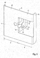
- FIG. 9 shows the back 12 of the flat part 1 together with the built-in mounting bracket 6 and the fixed flange 4.
- the flat part 1 engaging behind supporting edges 13 with the interposed positioned and in the disassembly opening 19 'engaged disassembly pocket 21.
Landscapes
- Engineering & Computer Science (AREA)
- General Engineering & Computer Science (AREA)
- Mechanical Engineering (AREA)
- Connection Of Plates (AREA)
Claims (15)
- Dispositif de fixation avec une partie plate (1), qui comprend une découpe (2) et avec un corps (3), qui comprend, sur sa circonférence, au moins à certains endroits, une bride (4), avec laquelle le corps (3) s'appuie, par l'intermédiaire d'un élément d'étanchéité (5) comprimable élastiquement au bord de la découpe (2), la bride (4) étant comprimée par une attache de fixation (6) en comprimant l'élément d'étanchéité (5) sont le bord, l'attache de fixation (6) comprenant une barrette (7), qui s'appuie contre la bride (48), et une patte d'enfichage (8) s'étendant globalement perpendiculairement à celle-ci, caractérisé en ce que la patte d'enfichage (8) traverse, avec son extrémité libre (9), une fente (10) au bord, et la patte d'enfichage (8) comprenant au moins un contre-support (11) qui s'appuie contre la partie arrière (12), opposée à la bride (4), du bord.
- Dispositif de fixation selon la revendication 1, dans lequel l'au moins un contre-support (11) comprend une arête d'appui (13) par l'intermédiaire de laquelle le contre-support (11) s'appuie contre la partie arrière (12), opposée à la bride (4) du bord.
- Dispositif de fixation selon la revendication 2, dans lequel l'arête d'appui (13) est disposée à une première distance de la barrette (7), qui est la somme d'une épaisseur de la bride (4), d'une épaisseur de la partie plate (1) au bord de la découpe (2) et d'une première épaisseur de l'élément d'étanchéité (5) comprimable élastiquement, lorsque l'élément d'étanchéité (5) se trouve dans un premier état de compression.
- Dispositif de fixation selon la revendication 2 ou 3, dans lequel l'attache de fixation (6) est une pièce en tôle formée dans laquelle la barrette (7) et la patte d'enfichage (8) sont des portions de tôle reliées entre elles par un rebord, le contre-support (11) étant une patte de tôle pouvant être précontrainte mécaniquement, qui est fixée par l'intermédiaire d'une première extrémité (15) dans une découpe (16) dans la patte d'enfichage (8) et l'extrémité opposée à la première extrémité (15) formant l'arête d'appui (13).
- Dispositif de fixation selon la revendication 4, dans lequel la patte de tôle dépasse, dans un état non sollicité, hors du plan formé par la patte d'enfichage (8) et se trouve, dans un état précontraint, dans le plan formé par la patte d'enfichage (8), l'arête d'appui (13) de la patte de tôle étant orientée en direction du rebord (14) lorsque la patte de tôle se trouve dans l'état précontraint.
- Dispositif de fixation selon l'une des revendications 3 à 5, dans lequel la patte d'enfichage (8) comprend au moins un contre-support supplémentaire (11) avec une arête d'appui supplémentaire (13), l'arête d'appui (13) étant disposée à une deuxième distance, différente de la première distance, de la barrette (7), qui est la somme de l'épaisseur de la bride (4), de l'épaisseur de la partie plate (1) au bord de la découpe (2) et d'une deuxième épaisseur de l'élément d'étanchéité comprimable élastiquement (5) lorsque l'élément d'étanchéité (5) se trouve dans un deuxième état de compression.
- Dispositif de fixation selon l'une des revendications précédentes, dans lequel l'élément d'étanchéité comprimable élastiquement (5) est un joint d'étanchéité en mousse de polyuréthane.
- Dispositif de fixation selon l'une des revendications précédentes, dans lequel la fente (10) est disposée à une distance de la bride (4) et la barrette (7) dépasse, avec une portion d'appui (17), pouvant être précontrainte élastiquement, de la bride (4) et est appuyée sur le bord de la découpe (2) avec une précontrainte mécanique.
- Dispositif de fixation selon la revendication 8, dans lequel la portion d'appui (17) comprend, à une distance (d) par rapport au rebord (14) reliant la patte d'enfichage (8) à la barrette (7), une entretoise (18) qui s'étend vers le bord et par l'intermédiaire de laquelle la portion d'appui (17) s'appuie sur le bord, de façon à ce que la patte d'enfichage (8) soit maintenue dans un état précontraint par le contre-support (11) dans la fente (10).
- Dispositif de fixation selon la revendication 9, dans lequel la barrette (7) comprend une portion d'appui supplémentaire (17') à une deuxième distance (e) du rebord (14), les portions d'appui (17, 17') s'étendant dans des directions opposées à partir du rebord (14) et la portion d'appui supplémentaire (17') s'appuyant, par l'intermédiaire d'une entretoise supplémentaire (18'), qui s'étend vers la bride (4), sur la bride (4).
- Dispositif de fixation selon la revendication 10, dans lequel l'entretoise supplémentaire (18') appuyée sur la bride (4) comprend, dans une direction perpendiculaire à la portion d'appui supplémentaire (17'), une dimension inférieure à la l'entretoise (18) dans une direction perpendiculaire à la portion d'appui (17), afin de permettre une compensation d'épaisseur pour la bride (4).
- Dispositif de fixation selon l'une des revendications 1 à 10, dans lequel le contre-support (11) comprend une patte de démontage (21) dépassant au-delà de l'arête d'appui (13) et s'étendant à partir de celle-ci, qui dépasse, dans une direction opposée à la direction d'insertion de la patte d'enfichage (8), à travers une ouverture de démontage (19') dans la partie plate (1), qui conduit vers la fente (10), de façon à ce que le contre-support (11) puisse être précontrainte par l'intermédiaire de la patte de démontage (21).
- Dispositif de fixation selon l'une des revendications précédentes, dans lequel, à la fente (10), correspond une ouverture de passage d'outil (19) par l'intermédiaire de laquelle le contre-support (11) est accessible à partir du côté avant (20) du bord.
- Dispositif de fixation selon la revendication 13, dans lequel l'ouverture de passage d'outil (19) conduit vers la fente (10).
- Dispositif de fixation selon l'une des revendications précédentes, dans lequel le corps (3) est un appareil de refroidissement mural et la partie plate (1) est élément de paroi d'une armoire de commande ou une porte d'armoire de commande.
Applications Claiming Priority (1)
| Application Number | Priority Date | Filing Date | Title |
|---|---|---|---|
| DE102015105544 | 2015-04-10 |
Publications (2)
| Publication Number | Publication Date |
|---|---|
| EP3078863A1 EP3078863A1 (fr) | 2016-10-12 |
| EP3078863B1 true EP3078863B1 (fr) | 2019-01-23 |
Family
ID=55661283
Family Applications (1)
| Application Number | Title | Priority Date | Filing Date |
|---|---|---|---|
| EP16163330.0A Active EP3078863B1 (fr) | 2015-04-10 | 2016-03-31 | Ensemble de fixation, en particulier pour la fixation d'un appareil de refroidissement sur une decoupe dans une porte d'armoire electrique ou une partie laterale d'armoire electrique |
Country Status (2)
| Country | Link |
|---|---|
| EP (1) | EP3078863B1 (fr) |
| DE (1) | DE102016105848A1 (fr) |
Cited By (1)
| Publication number | Priority date | Publication date | Assignee | Title |
|---|---|---|---|---|
| DE202019106094U1 (de) * | 2019-11-04 | 2021-02-05 | Ardex Anlagen Gmbh | Stützkonstruktion mit mehreren länglichen Profilelementen |
Family Cites Families (4)
| Publication number | Priority date | Publication date | Assignee | Title |
|---|---|---|---|---|
| DE8113742U1 (de) * | 1981-05-09 | 1981-08-06 | Süddeutsche Kühlerfabrik Julius Fr. Behr GmbH & Co KG, 7000 Stuttgart | Gehäuse für eine Kraftfahrzeug-Klima-, Heizungs- und/oder Belüftungsanlage |
| AT378042B (de) * | 1983-07-29 | 1985-06-10 | Krems Chemie Gmbh | Klemmprofil und klammer hiefuer |
| US6389658B1 (en) * | 1999-05-05 | 2002-05-21 | Thomas & Betts International, Inc. | Clip for mounting objects on a wall stud |
| US20110001026A1 (en) * | 2009-07-03 | 2011-01-06 | Egs Electrical Group Llc | Metal stud bracket |
-
2016
- 2016-03-31 EP EP16163330.0A patent/EP3078863B1/fr active Active
- 2016-03-31 DE DE102016105848.3A patent/DE102016105848A1/de not_active Ceased
Non-Patent Citations (1)
| Title |
|---|
| None * |
Cited By (1)
| Publication number | Priority date | Publication date | Assignee | Title |
|---|---|---|---|---|
| DE202019106094U1 (de) * | 2019-11-04 | 2021-02-05 | Ardex Anlagen Gmbh | Stützkonstruktion mit mehreren länglichen Profilelementen |
Also Published As
| Publication number | Publication date |
|---|---|
| DE102016105848A1 (de) | 2016-10-13 |
| EP3078863A1 (fr) | 2016-10-12 |
Similar Documents
| Publication | Publication Date | Title |
|---|---|---|
| EP2789931A1 (fr) | Dispositif de maintien pour la fixation d'un module de surface sur un support | |
| DE10357844B4 (de) | Befestigungssystem | |
| WO2012048686A1 (fr) | Écrou à cage | |
| EP2944737B1 (fr) | Dispositif de serrage destiné à relier des éléments profilés | |
| EP3529868B1 (fr) | Ensemble connecteur pour la connexion de deux châssis d'armoires électriques | |
| DE102010004686A1 (de) | Rastverbindungsmittel für eine Baugruppe | |
| EP3078863B1 (fr) | Ensemble de fixation, en particulier pour la fixation d'un appareil de refroidissement sur une decoupe dans une porte d'armoire electrique ou une partie laterale d'armoire electrique | |
| DE10236550A1 (de) | Haltevorrichtung für ein Leitungsstrang-Schuhelement | |
| DE29812707U1 (de) | Befestigungsvorrichtung für flächige Bauteile | |
| DE202021104122U1 (de) | Kopfanschlussteil zum Befestigen eines Hängestiels eines Kabeltragsystems an einer Decke | |
| DE102015006108B4 (de) | Klemmverbindungsvorrichtung | |
| EP2682681B1 (fr) | Dispositif de fixation pour fixer un corps de refroidissement ou de chauffage | |
| WO2013174674A1 (fr) | Système de fixation et tiroir | |
| DE2943191A1 (de) | Befestigungsanordnung fuer eine an einer blechplatte anzubringende mutter | |
| EP2775225B1 (fr) | Système comprenant un cadre de support, un élément de filtre pouvant être fixé à l'intérieur et au moins deux dispositifs de fixation | |
| DE19638316C1 (de) | Kraftfahrzeuglenksäulenbaueinheit | |
| DE102012106406A1 (de) | Fixierungsanordnung und Schubkasten | |
| EP4193434A1 (fr) | Dispositif de fixation, procédé, agencement et armoire de distribution | |
| DE3326070A1 (de) | Breitbandschelle | |
| EP3806695A1 (fr) | Tiroir et procédé de montage d'une paroi arrière sur un châssis latéral d'un tiroir | |
| EP4569237B1 (fr) | Pince à ressort et ensemble comprenant deux plaques reliées l'une à l'autre au moyen de la pince à ressort | |
| EP0389438B1 (fr) | Pare-neige | |
| EP1593786B1 (fr) | Dispositif de fixation pour éléments dans plaques de travail | |
| DE4404117A1 (de) | Halteelement aus Kunststoff, insbesondere für Rohrleitungen | |
| DE202023100438U1 (de) | Befestigungsklemme |
Legal Events
| Date | Code | Title | Description |
|---|---|---|---|
| PUAI | Public reference made under article 153(3) epc to a published international application that has entered the european phase |
Free format text: ORIGINAL CODE: 0009012 |
|
| AK | Designated contracting states |
Kind code of ref document: A1 Designated state(s): AL AT BE BG CH CY CZ DE DK EE ES FI FR GB GR HR HU IE IS IT LI LT LU LV MC MK MT NL NO PL PT RO RS SE SI SK SM TR |
|
| AX | Request for extension of the european patent |
Extension state: BA ME |
|
| STAA | Information on the status of an ep patent application or granted ep patent |
Free format text: STATUS: REQUEST FOR EXAMINATION WAS MADE |
|
| 17P | Request for examination filed |
Effective date: 20170407 |
|
| RBV | Designated contracting states (corrected) |
Designated state(s): AL AT BE BG CH CY CZ DE DK EE ES FI FR GB GR HR HU IE IS IT LI LT LU LV MC MK MT NL NO PL PT RO RS SE SI SK SM TR |
|
| GRAP | Despatch of communication of intention to grant a patent |
Free format text: ORIGINAL CODE: EPIDOSNIGR1 |
|
| STAA | Information on the status of an ep patent application or granted ep patent |
Free format text: STATUS: GRANT OF PATENT IS INTENDED |
|
| INTG | Intention to grant announced |
Effective date: 20181001 |
|
| GRAS | Grant fee paid |
Free format text: ORIGINAL CODE: EPIDOSNIGR3 |
|
| GRAA | (expected) grant |
Free format text: ORIGINAL CODE: 0009210 |
|
| STAA | Information on the status of an ep patent application or granted ep patent |
Free format text: STATUS: THE PATENT HAS BEEN GRANTED |
|
| AK | Designated contracting states |
Kind code of ref document: B1 Designated state(s): AL AT BE BG CH CY CZ DE DK EE ES FI FR GB GR HR HU IE IS IT LI LT LU LV MC MK MT NL NO PL PT RO RS SE SI SK SM TR |
|
| REG | Reference to a national code |
Ref country code: GB Ref legal event code: FG4D Free format text: NOT ENGLISH |
|
| REG | Reference to a national code |
Ref country code: CH Ref legal event code: EP |
|
| REG | Reference to a national code |
Ref country code: AT Ref legal event code: REF Ref document number: 1091686 Country of ref document: AT Kind code of ref document: T Effective date: 20190215 |
|
| REG | Reference to a national code |
Ref country code: IE Ref legal event code: FG4D Free format text: LANGUAGE OF EP DOCUMENT: GERMAN |
|
| REG | Reference to a national code |
Ref country code: DE Ref legal event code: R096 Ref document number: 502016003176 Country of ref document: DE |
|
| REG | Reference to a national code |
Ref country code: NL Ref legal event code: MP Effective date: 20190123 |
|
| PG25 | Lapsed in a contracting state [announced via postgrant information from national office to epo] |
Ref country code: NL Free format text: LAPSE BECAUSE OF FAILURE TO SUBMIT A TRANSLATION OF THE DESCRIPTION OR TO PAY THE FEE WITHIN THE PRESCRIBED TIME-LIMIT Effective date: 20190123 |
|
| PG25 | Lapsed in a contracting state [announced via postgrant information from national office to epo] |
Ref country code: FI Free format text: LAPSE BECAUSE OF FAILURE TO SUBMIT A TRANSLATION OF THE DESCRIPTION OR TO PAY THE FEE WITHIN THE PRESCRIBED TIME-LIMIT Effective date: 20190123 Ref country code: LT Free format text: LAPSE BECAUSE OF FAILURE TO SUBMIT A TRANSLATION OF THE DESCRIPTION OR TO PAY THE FEE WITHIN THE PRESCRIBED TIME-LIMIT Effective date: 20190123 Ref country code: ES Free format text: LAPSE BECAUSE OF FAILURE TO SUBMIT A TRANSLATION OF THE DESCRIPTION OR TO PAY THE FEE WITHIN THE PRESCRIBED TIME-LIMIT Effective date: 20190123 Ref country code: PL Free format text: LAPSE BECAUSE OF FAILURE TO SUBMIT A TRANSLATION OF THE DESCRIPTION OR TO PAY THE FEE WITHIN THE PRESCRIBED TIME-LIMIT Effective date: 20190123 Ref country code: NO Free format text: LAPSE BECAUSE OF FAILURE TO SUBMIT A TRANSLATION OF THE DESCRIPTION OR TO PAY THE FEE WITHIN THE PRESCRIBED TIME-LIMIT Effective date: 20190423 Ref country code: PT Free format text: LAPSE BECAUSE OF FAILURE TO SUBMIT A TRANSLATION OF THE DESCRIPTION OR TO PAY THE FEE WITHIN THE PRESCRIBED TIME-LIMIT Effective date: 20190523 Ref country code: SE Free format text: LAPSE BECAUSE OF FAILURE TO SUBMIT A TRANSLATION OF THE DESCRIPTION OR TO PAY THE FEE WITHIN THE PRESCRIBED TIME-LIMIT Effective date: 20190123 |
|
| PG25 | Lapsed in a contracting state [announced via postgrant information from national office to epo] |
Ref country code: LV Free format text: LAPSE BECAUSE OF FAILURE TO SUBMIT A TRANSLATION OF THE DESCRIPTION OR TO PAY THE FEE WITHIN THE PRESCRIBED TIME-LIMIT Effective date: 20190123 Ref country code: HR Free format text: LAPSE BECAUSE OF FAILURE TO SUBMIT A TRANSLATION OF THE DESCRIPTION OR TO PAY THE FEE WITHIN THE PRESCRIBED TIME-LIMIT Effective date: 20190123 Ref country code: RS Free format text: LAPSE BECAUSE OF FAILURE TO SUBMIT A TRANSLATION OF THE DESCRIPTION OR TO PAY THE FEE WITHIN THE PRESCRIBED TIME-LIMIT Effective date: 20190123 Ref country code: IS Free format text: LAPSE BECAUSE OF FAILURE TO SUBMIT A TRANSLATION OF THE DESCRIPTION OR TO PAY THE FEE WITHIN THE PRESCRIBED TIME-LIMIT Effective date: 20190523 Ref country code: BG Free format text: LAPSE BECAUSE OF FAILURE TO SUBMIT A TRANSLATION OF THE DESCRIPTION OR TO PAY THE FEE WITHIN THE PRESCRIBED TIME-LIMIT Effective date: 20190423 Ref country code: GR Free format text: LAPSE BECAUSE OF FAILURE TO SUBMIT A TRANSLATION OF THE DESCRIPTION OR TO PAY THE FEE WITHIN THE PRESCRIBED TIME-LIMIT Effective date: 20190424 |
|
| REG | Reference to a national code |
Ref country code: DE Ref legal event code: R097 Ref document number: 502016003176 Country of ref document: DE |
|
| PG25 | Lapsed in a contracting state [announced via postgrant information from national office to epo] |
Ref country code: DK Free format text: LAPSE BECAUSE OF FAILURE TO SUBMIT A TRANSLATION OF THE DESCRIPTION OR TO PAY THE FEE WITHIN THE PRESCRIBED TIME-LIMIT Effective date: 20190123 Ref country code: MC Free format text: LAPSE BECAUSE OF FAILURE TO SUBMIT A TRANSLATION OF THE DESCRIPTION OR TO PAY THE FEE WITHIN THE PRESCRIBED TIME-LIMIT Effective date: 20190123 Ref country code: CZ Free format text: LAPSE BECAUSE OF FAILURE TO SUBMIT A TRANSLATION OF THE DESCRIPTION OR TO PAY THE FEE WITHIN THE PRESCRIBED TIME-LIMIT Effective date: 20190123 Ref country code: SK Free format text: LAPSE BECAUSE OF FAILURE TO SUBMIT A TRANSLATION OF THE DESCRIPTION OR TO PAY THE FEE WITHIN THE PRESCRIBED TIME-LIMIT Effective date: 20190123 Ref country code: RO Free format text: LAPSE BECAUSE OF FAILURE TO SUBMIT A TRANSLATION OF THE DESCRIPTION OR TO PAY THE FEE WITHIN THE PRESCRIBED TIME-LIMIT Effective date: 20190123 Ref country code: AL Free format text: LAPSE BECAUSE OF FAILURE TO SUBMIT A TRANSLATION OF THE DESCRIPTION OR TO PAY THE FEE WITHIN THE PRESCRIBED TIME-LIMIT Effective date: 20190123 Ref country code: EE Free format text: LAPSE BECAUSE OF FAILURE TO SUBMIT A TRANSLATION OF THE DESCRIPTION OR TO PAY THE FEE WITHIN THE PRESCRIBED TIME-LIMIT Effective date: 20190123 |
|
| REG | Reference to a national code |
Ref country code: CH Ref legal event code: PL |
|
| PG25 | Lapsed in a contracting state [announced via postgrant information from national office to epo] |
Ref country code: SM Free format text: LAPSE BECAUSE OF FAILURE TO SUBMIT A TRANSLATION OF THE DESCRIPTION OR TO PAY THE FEE WITHIN THE PRESCRIBED TIME-LIMIT Effective date: 20190123 Ref country code: LU Free format text: LAPSE BECAUSE OF NON-PAYMENT OF DUE FEES Effective date: 20190331 |
|
| PLBE | No opposition filed within time limit |
Free format text: ORIGINAL CODE: 0009261 |
|
| STAA | Information on the status of an ep patent application or granted ep patent |
Free format text: STATUS: NO OPPOSITION FILED WITHIN TIME LIMIT |
|
| REG | Reference to a national code |
Ref country code: BE Ref legal event code: MM Effective date: 20190331 |
|
| 26N | No opposition filed |
Effective date: 20191024 |
|
| PG25 | Lapsed in a contracting state [announced via postgrant information from national office to epo] |
Ref country code: LI Free format text: LAPSE BECAUSE OF NON-PAYMENT OF DUE FEES Effective date: 20190331 Ref country code: CH Free format text: LAPSE BECAUSE OF NON-PAYMENT OF DUE FEES Effective date: 20190331 Ref country code: IE Free format text: LAPSE BECAUSE OF NON-PAYMENT OF DUE FEES Effective date: 20190331 |
|
| PG25 | Lapsed in a contracting state [announced via postgrant information from national office to epo] |
Ref country code: SI Free format text: LAPSE BECAUSE OF FAILURE TO SUBMIT A TRANSLATION OF THE DESCRIPTION OR TO PAY THE FEE WITHIN THE PRESCRIBED TIME-LIMIT Effective date: 20190123 Ref country code: BE Free format text: LAPSE BECAUSE OF NON-PAYMENT OF DUE FEES Effective date: 20190331 |
|
| PG25 | Lapsed in a contracting state [announced via postgrant information from national office to epo] |
Ref country code: TR Free format text: LAPSE BECAUSE OF FAILURE TO SUBMIT A TRANSLATION OF THE DESCRIPTION OR TO PAY THE FEE WITHIN THE PRESCRIBED TIME-LIMIT Effective date: 20190123 |
|
| PG25 | Lapsed in a contracting state [announced via postgrant information from national office to epo] |
Ref country code: MT Free format text: LAPSE BECAUSE OF FAILURE TO SUBMIT A TRANSLATION OF THE DESCRIPTION OR TO PAY THE FEE WITHIN THE PRESCRIBED TIME-LIMIT Effective date: 20190123 |
|
| PG25 | Lapsed in a contracting state [announced via postgrant information from national office to epo] |
Ref country code: CY Free format text: LAPSE BECAUSE OF FAILURE TO SUBMIT A TRANSLATION OF THE DESCRIPTION OR TO PAY THE FEE WITHIN THE PRESCRIBED TIME-LIMIT Effective date: 20190123 |
|
| PG25 | Lapsed in a contracting state [announced via postgrant information from national office to epo] |
Ref country code: HU Free format text: LAPSE BECAUSE OF FAILURE TO SUBMIT A TRANSLATION OF THE DESCRIPTION OR TO PAY THE FEE WITHIN THE PRESCRIBED TIME-LIMIT; INVALID AB INITIO Effective date: 20160331 |
|
| REG | Reference to a national code |
Ref country code: AT Ref legal event code: MM01 Ref document number: 1091686 Country of ref document: AT Kind code of ref document: T Effective date: 20210331 |
|
| PG25 | Lapsed in a contracting state [announced via postgrant information from national office to epo] |
Ref country code: MK Free format text: LAPSE BECAUSE OF FAILURE TO SUBMIT A TRANSLATION OF THE DESCRIPTION OR TO PAY THE FEE WITHIN THE PRESCRIBED TIME-LIMIT Effective date: 20190123 |
|
| PG25 | Lapsed in a contracting state [announced via postgrant information from national office to epo] |
Ref country code: AT Free format text: LAPSE BECAUSE OF NON-PAYMENT OF DUE FEES Effective date: 20210331 |
|
| P01 | Opt-out of the competence of the unified patent court (upc) registered |
Effective date: 20230525 |
|
| PGFP | Annual fee paid to national office [announced via postgrant information from national office to epo] |
Ref country code: IT Payment date: 20250331 Year of fee payment: 10 |
|
| PGFP | Annual fee paid to national office [announced via postgrant information from national office to epo] |
Ref country code: GB Payment date: 20260324 Year of fee payment: 11 |
|
| PGFP | Annual fee paid to national office [announced via postgrant information from national office to epo] |
Ref country code: DE Payment date: 20260320 Year of fee payment: 11 |
|
| PGFP | Annual fee paid to national office [announced via postgrant information from national office to epo] |
Ref country code: FR Payment date: 20260324 Year of fee payment: 11 |