EP3078890A1 - Vanne à deux étages - Google Patents
Vanne à deux étages Download PDFInfo
- Publication number
- EP3078890A1 EP3078890A1 EP16164559.3A EP16164559A EP3078890A1 EP 3078890 A1 EP3078890 A1 EP 3078890A1 EP 16164559 A EP16164559 A EP 16164559A EP 3078890 A1 EP3078890 A1 EP 3078890A1
- Authority
- EP
- European Patent Office
- Prior art keywords
- valve
- fluid
- pilot valve
- stage
- pilot
- Prior art date
- Legal status (The legal status is an assumption and is not a legal conclusion. Google has not performed a legal analysis and makes no representation as to the accuracy of the status listed.)
- Granted
Links
Images


Classifications
-
- F—MECHANICAL ENGINEERING; LIGHTING; HEATING; WEAPONS; BLASTING
- F16—ENGINEERING ELEMENTS AND UNITS; GENERAL MEASURES FOR PRODUCING AND MAINTAINING EFFECTIVE FUNCTIONING OF MACHINES OR INSTALLATIONS; THERMAL INSULATION IN GENERAL
- F16K—VALVES; TAPS; COCKS; ACTUATING-FLOATS; DEVICES FOR VENTING OR AERATING
- F16K31/00—Actuating devices; Operating means; Releasing devices
- F16K31/02—Actuating devices; Operating means; Releasing devices electric; magnetic
- F16K31/025—Actuating devices; Operating means; Releasing devices electric; magnetic actuated by thermo-electric means
-
- F—MECHANICAL ENGINEERING; LIGHTING; HEATING; WEAPONS; BLASTING
- F16—ENGINEERING ELEMENTS AND UNITS; GENERAL MEASURES FOR PRODUCING AND MAINTAINING EFFECTIVE FUNCTIONING OF MACHINES OR INSTALLATIONS; THERMAL INSULATION IN GENERAL
- F16K—VALVES; TAPS; COCKS; ACTUATING-FLOATS; DEVICES FOR VENTING OR AERATING
- F16K31/00—Actuating devices; Operating means; Releasing devices
- F16K31/12—Actuating devices; Operating means; Releasing devices actuated by fluid
- F16K31/36—Actuating devices; Operating means; Releasing devices actuated by fluid in which fluid from the circuit is constantly supplied to the fluid motor
- F16K31/40—Actuating devices; Operating means; Releasing devices actuated by fluid in which fluid from the circuit is constantly supplied to the fluid motor with electrically-actuated member in the discharge of the motor
- F16K31/402—Actuating devices; Operating means; Releasing devices actuated by fluid in which fluid from the circuit is constantly supplied to the fluid motor with electrically-actuated member in the discharge of the motor acting on a diaphragm
- F16K31/404—Actuating devices; Operating means; Releasing devices actuated by fluid in which fluid from the circuit is constantly supplied to the fluid motor with electrically-actuated member in the discharge of the motor acting on a diaphragm the discharge being effected through the diaphragm and being blockable by an electrically-actuated member making contact with the diaphragm
Definitions
- the present invention refers in general to a control device for a hydraulic circuit and, more specifically, to a two-stage valve configured to detect and manage the essential parameters of a fluid flowing in a hydraulic circuit.
- a hydraulic circuit comprises two essential components that carry out the conversion of mechanical energy into hydraulic energy and vice-versa. These two components consist of a pump and a motor. In a hydraulic circuit, in addition to these two components, it is required for there to be devices that carry out a control action on the fluid. Due to operating requirements of the circuits it is thus necessary to intervene on the essential hydraulic magnitudes of the fluid, in other words pressure and flow rate, as well as on the direction of the fluid flow.
- valves which can be grouped into three main categories:
- valves can only take up two states: actuated and not actuated. This means that the state taken up by the actuator of the valve, typically consisting of a solenoid, can cause the closure and the complete opening of the valve shutter, but it does not allow any intermediate position of such a shutter.
- a two-stage valve substantially consists of two directional valves joined in a single valve body.
- the control system of the two-stage valve typically consisting of a solenoid, acts on a small directional valve, or pilot valve, which uses the fluid of the hydraulic circuit to control the main valve.
- pilot valve which uses the fluid of the hydraulic circuit to control the main valve.
- This type of two-stage valve becomes necessary in large sized valves, which operate in high pressure hydraulic circuits, because the great forces required by the direct actuation of the shutter could not be generated only by the solenoid.
- the solenoid provides sufficient force to actuate only the pilot stage, of small size, which through suitable pilot lines hydraulically controls the shutter of the main valve.
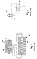
- FIG. 1 A typical scheme of a two-stage valve is shown in figures 1 and 2 .
- the pilot valve is indicated with reference numeral 100
- the main valve is indicated with reference numeral 102.
- the pilot valve 100 is provided with an actuator device 104, for example consisting of a solenoid.
- the shutter 106 of the pilot valve 100 moves axially to the left with reference to figure 1 .
- This allows the fluid, conveyed through suitable channels, to hydraulically actuate the shutter 108 of the main valve 102, axially moving it to the right with reference to figure 1 .
- a known two-stage valve therefore, is particularly bulky and heavy, since it consists of two distinct valves interconnected through suitable channels.
- a known two-stage valve in any case consumes a substantial amount of electrical energy in order to be able to operate correctly.
- a known two-stage valve in particular a two-stage valve with on/off function, is described in document EP 2 239 486 A1 .
- Another known two-stage valve is described in document US 2012/0151913 A1 .
- the purpose of the present invention is therefore to make a two-stage valve, both with on/off function, and with proportional function, which is able to solve the aforementioned drawbacks of the prior art in an extremely simple, cost-effective and particularly functional manner.
- a purpose of the present invention is to make a two-stage valve that allows a substantial reduction in size and weight with respect to a conventional two-stage valve.
- Another purpose of the present invention is to make a two-stage valve with valve normally closed functionality, which thus has the ability to autonomously interrupt the flow at the moment when there is no electrical power supply.
- a further purpose of the present invention is to make a two-stage valve that is able to reduce the electrical power and the consumption with respect to a conventional two-stage valve.
- Yet another purpose of the present invention is to make a two-stage valve that is able to detect and manage the essential parameters of the fluid flowing in the hydraulic circuit in which the valve itself is inserted.
- the two-stage valve according to the present invention is provided with a pilot stage that comprises an actuator device made of a shape-memory alloy (SMA), typically consisting of a wire of very small sections (between 20 and 500 micron in diameter).
- SMA shape-memory alloy
- the application, on a two-stage valve, of an actuator device made of a shape-memory alloy is particularly advantageous because, thanks to this technology, it is possible to obtain a pilot valve of very small dimensions and therefore easy to integrate in the main valve body without modifying the dimensions thereof.
- the two-stage valve according to the present invention is able to interrupt the fluid flow autonomously, even in the absence of an electrical power supply. This is due to the fact that inside the pilot stage a contrast element of the actuator piston acts that takes the pilot stage back into the closing condition at the moment when the electrical power supply of the shape memory element stops.
- the two-stage valve according to the present invention makes it possible to obtain a pilot stage perfectly integrated in the valve body and, therefore, with low volumes.
- the two-stage valve according to the present invention is also able to control high flow rates and pressures, absorbing a negligible electric power with respect to the hydraulic power.
- a proportional control based on a SMA actuator device makes it possible to reach high levels of precision in the modulation of the pilot flow, even with very limited ducts and flow rates. This makes it possible to manage the indirect proportional modulation of the flow on the main stage of the valve.
- the two-stage valve according to the present invention has a component made of a shape-memory alloy as actuator device for managing the fluid, through the pilot stage, it is intrinsic to use an electronic control board that manages the current needed to move the SMA wire.
- the control can also be of the proportional type, thus providing the possibility of modulating the flow of the pilot fluid to be managed in a linear manner.
- the electronic control board of the two-stage valve is configured to process, indirectly and thanks to the properties of the shape-memory alloy, some intrinsic parameters of the fluid, like for example the pressure, the flow rate and the temperature. Indeed, thanks to the fact that through the reading of the electrical resistance of the SMA wire it is possible to obtain the length of the wire itself and therefore the actual opening position of the valve, through the reading of the energy injected it is possible to understand the force with which the wire is acting and therefore indirectly the pressure of the fluid. Moreover, considering that the total amount of energy need to reach the transition of the shape-memory alloy is also a function of the temperature of the SMA actuator device, it will be simple to make these parameters available without needing the use of specific sensors on the two-stage valve.
- the same electronic control board of the two-stage valve can also integrate a wireless remote communication module (for example with Wi-Fi technology) configured to make the aforementioned "field" parameters of the fluid available.
- a wireless remote communication module for example with Wi-Fi technology
- Such a remote communication module can interface and therefore can communicate wirelessly with portable devices, such as smartphones, tablets or similar, or can interface with the internet and therefore communicate with remote terminals via web.
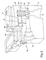
- the two-stage valve 10 comprises a first stage, constituted by a main valve body 12 provided with at least one fluid inlet duct 14 for inletting fluid into the main valve and with at least one fluid outlet duct 16 for outletting fluid out from the main valve. Between the fluid inlet duct 14 of the main valve and the fluid outlet duct 16 of the main valve at least one shutter element 18 of the main valve is interposed, configured to put selectively in fluid communication such a fluid inlet duct 14 of the main valve with such a fluid outlet duct 16 of the main valve.
- the two-stage valve 10 also comprises a second stage, constituted by a pilot valve body 20 provided with at least one fluid inlet duct 22 for inletting fluid into the pilot valve and with at least one fluid outlet duct 24 for outletting fluid out from the pilot valve.
- the fluid inlet duct 22 of the pilot valve is put in fluid communication with the fluid inlet duct 14 of the main valve, whereas the fluid outlet duct 24 of the pilot valve is put in fluid communication with the fluid outlet duct 16 of the main valve.
- At least one shutter element 26 of the pilot valve is interposed, configured to put selectively in fluid communication such a fluid inlet duct 22 of the pilot valve with such a fluid outlet duct 24 of the pilot valve.
- the opening of the shutter element 26 of the pilot valve generates a fluid flow passing through the fluid inlet duct 22 of the pilot valve and the fluid outlet duct 24 of the pilot valve, the pressure of such a fluid flow generating the opening of the shutter element 18 of the main valve.
- the shutter element 26 of the pilot valve consists of a piston movable with rectilinear motion under the action of an actuator device 28 comprising at least one wire 30 made of a shape-memory alloy.
- the wire 30 is able to apply a force, preferably a traction force, onto the shutter element 26 of the pilot valve by means of the temperature variation (heating) determined by Joule effect by the passage of an electric current through the wire 30 itself.
- the shutter element 26 of the pilot valve is in normally closed condition when the respective actuator device 28 is not activated.
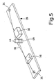
- the shutter element 26 of the pilot valve is kept in normally closed condition by a thruster element 44 ( figure 5 ) belonging to the actuator device 28 and actuated by an elastic element 46, like for example a contrast spring operating by compression.
- the traction force exerted by the wire 30 made of a shape-memory alloy on the shutter element 26 of the pilot valve where such a force is generated by the passage of electric current through the wire 30 itself, allows the elastic force generated by the elastic element 46 to be overcome, so as to take such a shutter element 26 of the pilot valve into partially or totally open condition.
- an elastic separation membrane 48 is also interposed ( figure 4 ), kept in compression by a squash flange 50.
- the traction force exerted by the wire 30 must compensate only the contrast force of the elastic element 46, since the pressure, and therefore the relative force exerted by the fluid, promotes the traction force itself of the wire 30. In this way, it is possible to use shape memory wires 30 with small sections, therefore with higher switching speeds, also keeping the mechanical stress of the wire 30 itself and therefore the useful life of the two-stage valve 10 under control, since it is independent of the pressure generated by the fluid.
- the actuator device 28 is thus provided with an electronic control and communication system comprising a control board 32 in turn provided with respective power supply connections.
- the control board 32 is also provided with operative connection means 34, for example consisting of one or more mechanical and electrical crimps, with the wire 30 made of a shape-memory alloy.
- the control board 32 is configured to indirectly obtain determined physical parameters of the fluid through the characteristics of the wire 30 made of a shape-memory alloy.
- the electronic control and communication system is further provided with a wireless remote communication module 36, interfaceable via web with remote terminals and/or with portable devices and configured to make available the physical parameters of the fluid on such remote terminals and/or portable devices.
- the control board 32 can be provided with means for detecting the relative position of the thruster element 44.
- These detecting means can consist of one or more sensors, like for example position sensors of the magnetic, capacitive, optical, Hall effect type, etc.
- these detecting means can consist of a device for reading the electrical resistance of the wire 30 made of a shape-memory alloy.
- the operating principle of the two-stage valve 10 provides the shutter element 18 of the main valve, which consists of a piston movable with rectilinear motion, to be in the normally closed position pushed both by the action of a contrast spring 38, and by the pressure of the fluid flowing in the two-stage valve 10 itself.
- the shutter element 18 of the main valve is internally hollow and inside it defines a balancing chamber 40 in which the fluid is under pressure when the fluid inlet duct 22 of the pilot valve is kept closed by the shutter element 26 of the pilot valve, as well as because the shutter element 18 of the main valve is equipped with a membrane 42 that externally separates the main valve body 12 and the pilot valve body 20.
- the at least partial opening of the shutter element 26 of the pilot valve is obtained, so that the fluid inlet duct 22 of the pilot valve is put in communication with the fluid outlet duct 24 of the pilot valve and, therefore, with the fluid outlet duct 16 of the main valve. Consequently, both the pressure inside the balancing chamber 40 of the shutter element 18 of the main valve, and the closing thrust of such a shutter element 18 of the main valve decrease. Therefore, the shutter element 18 of the main valve opens pushed by the pressure of the fluid contained in the fluid inlet duct 14 in the main valve, determining the passage of the fluid flow in the main valve body 12.
- the two-stage valve 10 is suitably sized, by modulating the stroke of the shutter element 26 of the pilot valve in a controlled manner, it is possible to obtain controlled variations of the pressure in the balancing chamber 40. Consequently, it is possible to equally proportionally modulate the stroke of the shutter element 18 of the main valve, obtaining different flow rates of the fluid flow in the main valve body 12.
- the control board 32 inserted inside the actuator device 28 is provided with a modulator configured to modulate in amplitude the electric current necessary to heat the wire 30 made of a shape-memory alloy, so as to obtain the controlled displacement of the shutter element 26 of the pilot valve.
- a modulator configured to modulate in amplitude the electric current necessary to heat the wire 30 made of a shape-memory alloy, so as to obtain the controlled displacement of the shutter element 26 of the pilot valve.
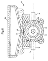
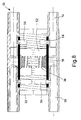
- FIG. 6 shows a second embodiment of the two-stage valve 10 according to the present invention.
- This two-stage valve 10 is actually a double valve, with a pair of fluid inlet ducts 22 of the pilot valve, completely independent from one another, and a corresponding pair of fluid outlet ducts 24 of the pilot valve, also completely independent from one another.
- Two distinct shutter elements 26 of the pilot valve are thus provided, able to be controlled independently and proportionally through the control board 32.
- the two-stage valve 10 has a high level of integration in order to keep the dimensions as compact as possible.
- the two-stage valve 10 is provided with a fluid flow distribution system arranged outside of a pilot chamber 52 that puts in fluid communication, through the interposition of a joining duct 56, the fluid inlet duct 14 of the main valve and the fluid inlet ducts 22 of the pilot valve.
- the fluid flow distribution system makes the two-stage valve 10 even more compact and allows the fluid inlet ducts 22 of the pilot valve and the fluid outlet ducts 24 of the pilot valve to be formed directly and at least partially on the main valve body 12.
- the main valve body 12 is made integral with the pilot valve body 20.
- the fluid flow distribution system comprises a set of outer ducts that form a distribution chamber 54, having a substantially circular shape, which surrounds the central pilot chamber 52.
- the distribution chamber 54 is arranged in fluid connection with the elastic separation membrane 48 on which the two shutter elements 26 of the pilot valve act. These two shutter elements 26 determine the calibrated passage of fluid in order to unbalance the pressure in the pilot chamber 52.
- the fluid enters into the two-stage valve 10 through the fluid inlet duct 14 of the main valve, passes through the joining duct 56 and flows into the pilot chamber 52.
- the fluid is thus managed by the pilot valve through the respective inlet 22 and outlet 24 ducts.
- the fluid outlet ducts 24 of the pilot valve send such fluid into the distribution chamber 54 and, from here, towards the fluid outlet duct 16 of the main valve.
- the substantially circular shape of the distribution chamber 54 makes it possible to arrange the fluid inlet duct 14 in the main valve and the fluid outlet duct 16 of the main valve in any radial position with respect to the distribution chamber 54 itself.
- the two-stage valve of the present invention also obtains the following advantages:
- the calibrated pilot hole which determines the unbalancing of the pressures and therefore the operation of the valve, is obtained directly in the valve body and not in the mobile element. This involves a higher level of reliability and precision in the management of the pressure variation, particularly in proportional terms.
- the two-stage valve of the present invention thus conceived can in any case undergo numerous modifications and variants, all of which are covered by the same inventive concept; moreover, all of the details can be replaced by technically equivalent elements.
- the materials used, as well as the shapes and sizes, can be whatever according to the technical requirements.
Landscapes
- Engineering & Computer Science (AREA)
- General Engineering & Computer Science (AREA)
- Mechanical Engineering (AREA)
- Fluid-Driven Valves (AREA)
Applications Claiming Priority (1)
| Application Number | Priority Date | Filing Date | Title |
|---|---|---|---|
| ITUB20150021 | 2015-04-09 |
Publications (2)
| Publication Number | Publication Date |
|---|---|
| EP3078890A1 true EP3078890A1 (fr) | 2016-10-12 |
| EP3078890B1 EP3078890B1 (fr) | 2018-03-21 |
Family
ID=53490124
Family Applications (1)
| Application Number | Title | Priority Date | Filing Date |
|---|---|---|---|
| EP16164559.3A Active EP3078890B1 (fr) | 2015-04-09 | 2016-04-08 | Vanne à deux étages |
Country Status (1)
| Country | Link |
|---|---|
| EP (1) | EP3078890B1 (fr) |
Cited By (1)
| Publication number | Priority date | Publication date | Assignee | Title |
|---|---|---|---|---|
| IT201900012552A1 (it) | 2019-07-22 | 2021-01-22 | Getters Spa | Valvola per fluidi a due zone a pressioni uguali con elemento di controllo in lega a memoria di forma |
Families Citing this family (2)
| Publication number | Priority date | Publication date | Assignee | Title |
|---|---|---|---|---|
| DE102023208359B4 (de) | 2023-08-31 | 2025-06-26 | Conti Temic Microelectronic Gmbh | Pneumatisches Ventil mit einem SMA-Aktuator |
| DE102024204954B4 (de) * | 2024-05-28 | 2026-04-30 | Aumovio Germany Gmbh | Pneumatisches Ventil mit einem SMA-Aktuator |
Citations (3)
| Publication number | Priority date | Publication date | Assignee | Title |
|---|---|---|---|---|
| EP2239486A1 (fr) | 2009-04-08 | 2010-10-13 | Kohler Mira Limited | Valves |
| US20120151913A1 (en) | 2010-12-15 | 2012-06-21 | Leonid Foshansky | Memory alloy-actuated apparatus and methods for making and using the same |
| WO2015015370A1 (fr) * | 2013-08-01 | 2015-02-05 | Fluid-O-Tech S.R.L. | Soupape de dosage pour machines de traitement de fluide, en particulier pour la production et la distribution de boissons. |
-
2016
- 2016-04-08 EP EP16164559.3A patent/EP3078890B1/fr active Active
Patent Citations (3)
| Publication number | Priority date | Publication date | Assignee | Title |
|---|---|---|---|---|
| EP2239486A1 (fr) | 2009-04-08 | 2010-10-13 | Kohler Mira Limited | Valves |
| US20120151913A1 (en) | 2010-12-15 | 2012-06-21 | Leonid Foshansky | Memory alloy-actuated apparatus and methods for making and using the same |
| WO2015015370A1 (fr) * | 2013-08-01 | 2015-02-05 | Fluid-O-Tech S.R.L. | Soupape de dosage pour machines de traitement de fluide, en particulier pour la production et la distribution de boissons. |
Cited By (2)
| Publication number | Priority date | Publication date | Assignee | Title |
|---|---|---|---|---|
| IT201900012552A1 (it) | 2019-07-22 | 2021-01-22 | Getters Spa | Valvola per fluidi a due zone a pressioni uguali con elemento di controllo in lega a memoria di forma |
| WO2021013836A1 (fr) | 2019-07-22 | 2021-01-28 | Saes Getters S.P.A. | Soupape fluidique à deux zones à pression équilibrée ayant un élément de commande en alliage à mémoire de forme |
Also Published As
| Publication number | Publication date |
|---|---|
| EP3078890B1 (fr) | 2018-03-21 |
Similar Documents
| Publication | Publication Date | Title |
|---|---|---|
| US8585776B2 (en) | Mesofluidic controlled robotic or prosthetic finger | |
| KR102189613B1 (ko) | 밸브 유닛 및 밸브 유닛을 포함하는 유체 작업 기계 | |
| CN101855458B (zh) | 先导控制的、用于控制涡轮机的作动缸的换向阀 | |
| US10767667B2 (en) | Electronically controlled valve, hydraulic pump, and hydraulic pump system | |
| WO2010025354A3 (fr) | Système de commande pour une machine ayant une procédure de réchauffage hydraulique | |
| US20120199768A1 (en) | Mesofluidic digital valve | |
| US20120199763A1 (en) | Mesofluidic shape memory alloy valve | |
| EP3078890B1 (fr) | Vanne à deux étages | |
| CN106133422B (zh) | 方向控制阀 | |
| JP2011163508A (ja) | 油圧制御装置 | |
| US11092173B2 (en) | Flow control for an actuator | |
| US8616237B2 (en) | Mesofluidic two stage digital valve | |
| JP5756229B2 (ja) | 油圧回路 | |
| US9880565B1 (en) | Two-stage valve | |
| CN101855457A (zh) | 具有加热回路的液压系统 | |
| CN104110412B (zh) | 流量调节阀结构组件 | |
| KR102530260B1 (ko) | 전자 비례 밸브 | |
| US8313082B2 (en) | Proportional position feedback hydraulic servo system | |
| JP7480273B2 (ja) | 形状記憶合金制御素子を具備する平衡圧力2ゾーン流体弁 | |
| CN106062382B (zh) | 阀组件 | |
| EP3080499A1 (fr) | Ensemble clapet à billes | |
| AU2016238916A1 (en) | Two-stage valve | |
| US20190389564A1 (en) | Hydraulic stage | |
| CN113446279B (zh) | 高压油路切换装置及液压系统 | |
| US9032861B2 (en) | Arrangement for providing a variable throttle cross-section for a fluid flow |
Legal Events
| Date | Code | Title | Description |
|---|---|---|---|
| PUAI | Public reference made under article 153(3) epc to a published international application that has entered the european phase |
Free format text: ORIGINAL CODE: 0009012 |
|
| AK | Designated contracting states |
Kind code of ref document: A1 Designated state(s): AL AT BE BG CH CY CZ DE DK EE ES FI FR GB GR HR HU IE IS IT LI LT LU LV MC MK MT NL NO PL PT RO RS SE SI SK SM TR |
|
| AX | Request for extension of the european patent |
Extension state: BA ME |
|
| STAA | Information on the status of an ep patent application or granted ep patent |
Free format text: STATUS: REQUEST FOR EXAMINATION WAS MADE |
|
| 17P | Request for examination filed |
Effective date: 20170411 |
|
| RBV | Designated contracting states (corrected) |
Designated state(s): AL AT BE BG CH CY CZ DE DK EE ES FI FR GB GR HR HU IE IS IT LI LT LU LV MC MK MT NL NO PL PT RO RS SE SI SK SM TR |
|
| GRAP | Despatch of communication of intention to grant a patent |
Free format text: ORIGINAL CODE: EPIDOSNIGR1 |
|
| STAA | Information on the status of an ep patent application or granted ep patent |
Free format text: STATUS: GRANT OF PATENT IS INTENDED |
|
| INTG | Intention to grant announced |
Effective date: 20171010 |
|
| GRAS | Grant fee paid |
Free format text: ORIGINAL CODE: EPIDOSNIGR3 |
|
| GRAA | (expected) grant |
Free format text: ORIGINAL CODE: 0009210 |
|
| STAA | Information on the status of an ep patent application or granted ep patent |
Free format text: STATUS: THE PATENT HAS BEEN GRANTED |
|
| AK | Designated contracting states |
Kind code of ref document: B1 Designated state(s): AL AT BE BG CH CY CZ DE DK EE ES FI FR GB GR HR HU IE IS IT LI LT LU LV MC MK MT NL NO PL PT RO RS SE SI SK SM TR |
|
| REG | Reference to a national code |
Ref country code: GB Ref legal event code: FG4D |
|
| REG | Reference to a national code |
Ref country code: CH Ref legal event code: EP |
|
| REG | Reference to a national code |
Ref country code: AT Ref legal event code: REF Ref document number: 981473 Country of ref document: AT Kind code of ref document: T Effective date: 20180415 |
|
| REG | Reference to a national code |
Ref country code: IE Ref legal event code: FG4D |
|
| REG | Reference to a national code |
Ref country code: DE Ref legal event code: R096 Ref document number: 602016002074 Country of ref document: DE |
|
| REG | Reference to a national code |
Ref country code: FR Ref legal event code: PLFP Year of fee payment: 3 |
|
| REG | Reference to a national code |
Ref country code: NL Ref legal event code: MP Effective date: 20180321 |
|
| PG25 | Lapsed in a contracting state [announced via postgrant information from national office to epo] |
Ref country code: HR Free format text: LAPSE BECAUSE OF FAILURE TO SUBMIT A TRANSLATION OF THE DESCRIPTION OR TO PAY THE FEE WITHIN THE PRESCRIBED TIME-LIMIT Effective date: 20180321 Ref country code: FI Free format text: LAPSE BECAUSE OF FAILURE TO SUBMIT A TRANSLATION OF THE DESCRIPTION OR TO PAY THE FEE WITHIN THE PRESCRIBED TIME-LIMIT Effective date: 20180321 Ref country code: LT Free format text: LAPSE BECAUSE OF FAILURE TO SUBMIT A TRANSLATION OF THE DESCRIPTION OR TO PAY THE FEE WITHIN THE PRESCRIBED TIME-LIMIT Effective date: 20180321 Ref country code: CY Free format text: LAPSE BECAUSE OF FAILURE TO SUBMIT A TRANSLATION OF THE DESCRIPTION OR TO PAY THE FEE WITHIN THE PRESCRIBED TIME-LIMIT Effective date: 20180321 Ref country code: NO Free format text: LAPSE BECAUSE OF FAILURE TO SUBMIT A TRANSLATION OF THE DESCRIPTION OR TO PAY THE FEE WITHIN THE PRESCRIBED TIME-LIMIT Effective date: 20180621 |
|
| REG | Reference to a national code |
Ref country code: LT Ref legal event code: MG4D |
|
| REG | Reference to a national code |
Ref country code: AT Ref legal event code: MK05 Ref document number: 981473 Country of ref document: AT Kind code of ref document: T Effective date: 20180321 |
|
| PG25 | Lapsed in a contracting state [announced via postgrant information from national office to epo] |
Ref country code: RS Free format text: LAPSE BECAUSE OF FAILURE TO SUBMIT A TRANSLATION OF THE DESCRIPTION OR TO PAY THE FEE WITHIN THE PRESCRIBED TIME-LIMIT Effective date: 20180321 Ref country code: BG Free format text: LAPSE BECAUSE OF FAILURE TO SUBMIT A TRANSLATION OF THE DESCRIPTION OR TO PAY THE FEE WITHIN THE PRESCRIBED TIME-LIMIT Effective date: 20180621 Ref country code: GR Free format text: LAPSE BECAUSE OF FAILURE TO SUBMIT A TRANSLATION OF THE DESCRIPTION OR TO PAY THE FEE WITHIN THE PRESCRIBED TIME-LIMIT Effective date: 20180622 Ref country code: SE Free format text: LAPSE BECAUSE OF FAILURE TO SUBMIT A TRANSLATION OF THE DESCRIPTION OR TO PAY THE FEE WITHIN THE PRESCRIBED TIME-LIMIT Effective date: 20180321 Ref country code: LV Free format text: LAPSE BECAUSE OF FAILURE TO SUBMIT A TRANSLATION OF THE DESCRIPTION OR TO PAY THE FEE WITHIN THE PRESCRIBED TIME-LIMIT Effective date: 20180321 |
|
| PG25 | Lapsed in a contracting state [announced via postgrant information from national office to epo] |
Ref country code: ES Free format text: LAPSE BECAUSE OF FAILURE TO SUBMIT A TRANSLATION OF THE DESCRIPTION OR TO PAY THE FEE WITHIN THE PRESCRIBED TIME-LIMIT Effective date: 20180321 Ref country code: NL Free format text: LAPSE BECAUSE OF FAILURE TO SUBMIT A TRANSLATION OF THE DESCRIPTION OR TO PAY THE FEE WITHIN THE PRESCRIBED TIME-LIMIT Effective date: 20180321 Ref country code: AL Free format text: LAPSE BECAUSE OF FAILURE TO SUBMIT A TRANSLATION OF THE DESCRIPTION OR TO PAY THE FEE WITHIN THE PRESCRIBED TIME-LIMIT Effective date: 20180321 Ref country code: PL Free format text: LAPSE BECAUSE OF FAILURE TO SUBMIT A TRANSLATION OF THE DESCRIPTION OR TO PAY THE FEE WITHIN THE PRESCRIBED TIME-LIMIT Effective date: 20180321 Ref country code: RO Free format text: LAPSE BECAUSE OF FAILURE TO SUBMIT A TRANSLATION OF THE DESCRIPTION OR TO PAY THE FEE WITHIN THE PRESCRIBED TIME-LIMIT Effective date: 20180321 Ref country code: EE Free format text: LAPSE BECAUSE OF FAILURE TO SUBMIT A TRANSLATION OF THE DESCRIPTION OR TO PAY THE FEE WITHIN THE PRESCRIBED TIME-LIMIT Effective date: 20180321 |
|
| PG25 | Lapsed in a contracting state [announced via postgrant information from national office to epo] |
Ref country code: SK Free format text: LAPSE BECAUSE OF FAILURE TO SUBMIT A TRANSLATION OF THE DESCRIPTION OR TO PAY THE FEE WITHIN THE PRESCRIBED TIME-LIMIT Effective date: 20180321 Ref country code: CZ Free format text: LAPSE BECAUSE OF FAILURE TO SUBMIT A TRANSLATION OF THE DESCRIPTION OR TO PAY THE FEE WITHIN THE PRESCRIBED TIME-LIMIT Effective date: 20180321 Ref country code: SM Free format text: LAPSE BECAUSE OF FAILURE TO SUBMIT A TRANSLATION OF THE DESCRIPTION OR TO PAY THE FEE WITHIN THE PRESCRIBED TIME-LIMIT Effective date: 20180321 Ref country code: AT Free format text: LAPSE BECAUSE OF FAILURE TO SUBMIT A TRANSLATION OF THE DESCRIPTION OR TO PAY THE FEE WITHIN THE PRESCRIBED TIME-LIMIT Effective date: 20180321 |
|
| REG | Reference to a national code |
Ref country code: BE Ref legal event code: MM Effective date: 20180430 |
|
| PG25 | Lapsed in a contracting state [announced via postgrant information from national office to epo] |
Ref country code: PT Free format text: LAPSE BECAUSE OF FAILURE TO SUBMIT A TRANSLATION OF THE DESCRIPTION OR TO PAY THE FEE WITHIN THE PRESCRIBED TIME-LIMIT Effective date: 20180723 |
|
| REG | Reference to a national code |
Ref country code: DE Ref legal event code: R097 Ref document number: 602016002074 Country of ref document: DE |
|
| REG | Reference to a national code |
Ref country code: IE Ref legal event code: MM4A |
|
| PLBE | No opposition filed within time limit |
Free format text: ORIGINAL CODE: 0009261 |
|
| STAA | Information on the status of an ep patent application or granted ep patent |
Free format text: STATUS: NO OPPOSITION FILED WITHIN TIME LIMIT |
|
| PG25 | Lapsed in a contracting state [announced via postgrant information from national office to epo] |
Ref country code: LU Free format text: LAPSE BECAUSE OF NON-PAYMENT OF DUE FEES Effective date: 20180408 Ref country code: MC Free format text: LAPSE BECAUSE OF FAILURE TO SUBMIT A TRANSLATION OF THE DESCRIPTION OR TO PAY THE FEE WITHIN THE PRESCRIBED TIME-LIMIT Effective date: 20180321 Ref country code: DK Free format text: LAPSE BECAUSE OF FAILURE TO SUBMIT A TRANSLATION OF THE DESCRIPTION OR TO PAY THE FEE WITHIN THE PRESCRIBED TIME-LIMIT Effective date: 20180321 |
|
| 26N | No opposition filed |
Effective date: 20190102 |
|
| PG25 | Lapsed in a contracting state [announced via postgrant information from national office to epo] |
Ref country code: BE Free format text: LAPSE BECAUSE OF NON-PAYMENT OF DUE FEES Effective date: 20180430 |
|
| PG25 | Lapsed in a contracting state [announced via postgrant information from national office to epo] |
Ref country code: IE Free format text: LAPSE BECAUSE OF NON-PAYMENT OF DUE FEES Effective date: 20180408 |
|
| PG25 | Lapsed in a contracting state [announced via postgrant information from national office to epo] |
Ref country code: SI Free format text: LAPSE BECAUSE OF FAILURE TO SUBMIT A TRANSLATION OF THE DESCRIPTION OR TO PAY THE FEE WITHIN THE PRESCRIBED TIME-LIMIT Effective date: 20180321 |
|
| PG25 | Lapsed in a contracting state [announced via postgrant information from national office to epo] |
Ref country code: MT Free format text: LAPSE BECAUSE OF NON-PAYMENT OF DUE FEES Effective date: 20180408 |
|
| PG25 | Lapsed in a contracting state [announced via postgrant information from national office to epo] |
Ref country code: TR Free format text: LAPSE BECAUSE OF FAILURE TO SUBMIT A TRANSLATION OF THE DESCRIPTION OR TO PAY THE FEE WITHIN THE PRESCRIBED TIME-LIMIT Effective date: 20180321 |
|
| PG25 | Lapsed in a contracting state [announced via postgrant information from national office to epo] |
Ref country code: HU Free format text: LAPSE BECAUSE OF FAILURE TO SUBMIT A TRANSLATION OF THE DESCRIPTION OR TO PAY THE FEE WITHIN THE PRESCRIBED TIME-LIMIT; INVALID AB INITIO Effective date: 20160408 Ref country code: MK Free format text: LAPSE BECAUSE OF NON-PAYMENT OF DUE FEES Effective date: 20180321 |
|
| PG25 | Lapsed in a contracting state [announced via postgrant information from national office to epo] |
Ref country code: IS Free format text: LAPSE BECAUSE OF FAILURE TO SUBMIT A TRANSLATION OF THE DESCRIPTION OR TO PAY THE FEE WITHIN THE PRESCRIBED TIME-LIMIT Effective date: 20180721 |
|
| PGFP | Annual fee paid to national office [announced via postgrant information from national office to epo] |
Ref country code: GB Payment date: 20240229 Year of fee payment: 9 |
|
| PGFP | Annual fee paid to national office [announced via postgrant information from national office to epo] |
Ref country code: DE Payment date: 20250402 Year of fee payment: 10 |
|
| PGFP | Annual fee paid to national office [announced via postgrant information from national office to epo] |
Ref country code: IT Payment date: 20250408 Year of fee payment: 10 |
|
| PGFP | Annual fee paid to national office [announced via postgrant information from national office to epo] |
Ref country code: FR Payment date: 20250401 Year of fee payment: 10 |
|
| PGFP | Annual fee paid to national office [announced via postgrant information from national office to epo] |
Ref country code: CH Payment date: 20250501 Year of fee payment: 10 |
|
| GBPC | Gb: european patent ceased through non-payment of renewal fee |
Effective date: 20250408 |
|
| PG25 | Lapsed in a contracting state [announced via postgrant information from national office to epo] |
Ref country code: GB Free format text: LAPSE BECAUSE OF NON-PAYMENT OF DUE FEES Effective date: 20250408 |