EP3078923B1 - Ensemble pylône et cadre de support réglable en hauter - Google Patents
Ensemble pylône et cadre de support réglable en hauter Download PDFInfo
- Publication number
- EP3078923B1 EP3078923B1 EP16164001.6A EP16164001A EP3078923B1 EP 3078923 B1 EP3078923 B1 EP 3078923B1 EP 16164001 A EP16164001 A EP 16164001A EP 3078923 B1 EP3078923 B1 EP 3078923B1
- Authority
- EP
- European Patent Office
- Prior art keywords
- frame
- pylon
- assembly
- frame members
- members
- Prior art date
- Legal status (The legal status is an assumption and is not a legal conclusion. Google has not performed a legal analysis and makes no representation as to the accuracy of the status listed.)
- Active
Links
Images




Classifications
-
- F—MECHANICAL ENGINEERING; LIGHTING; HEATING; WEAPONS; BLASTING
- F16—ENGINEERING ELEMENTS AND UNITS; GENERAL MEASURES FOR PRODUCING AND MAINTAINING EFFECTIVE FUNCTIONING OF MACHINES OR INSTALLATIONS; THERMAL INSULATION IN GENERAL
- F16M—FRAMES, CASINGS OR BEDS OF ENGINES, MACHINES OR APPARATUS, NOT SPECIFIC TO ENGINES, MACHINES OR APPARATUS PROVIDED FOR ELSEWHERE; STANDS; SUPPORTS
- F16M11/00—Stands or trestles as supports for apparatus or articles placed thereon ; Stands for scientific apparatus such as gravitational force meters
- F16M11/20—Undercarriages with or without wheels
- F16M11/24—Undercarriages with or without wheels changeable in height or length of legs, also for transport only, e.g. by means of tubes screwed into each other
-
- E—FIXED CONSTRUCTIONS
- E04—BUILDING
- E04H—BUILDINGS OR LIKE STRUCTURES FOR PARTICULAR PURPOSES; SWIMMING OR SPLASH BATHS OR POOLS; MASTS; FENCING; TENTS OR CANOPIES, IN GENERAL
- E04H12/00—Towers; Masts or poles; Chimney stacks; Water-towers; Methods of erecting such structures
-
- F—MECHANICAL ENGINEERING; LIGHTING; HEATING; WEAPONS; BLASTING
- F16—ENGINEERING ELEMENTS AND UNITS; GENERAL MEASURES FOR PRODUCING AND MAINTAINING EFFECTIVE FUNCTIONING OF MACHINES OR INSTALLATIONS; THERMAL INSULATION IN GENERAL
- F16B—DEVICES FOR FASTENING OR SECURING CONSTRUCTIONAL ELEMENTS OR MACHINE PARTS TOGETHER, e.g. NAILS, BOLTS, CIRCLIPS, CLAMPS, CLIPS OR WEDGES; JOINTS OR JOINTING
- F16B7/00—Connections of rods or tubes, e.g. of non-circular section, mutually, including resilient connections
- F16B7/18—Connections of rods or tubes, e.g. of non-circular section, mutually, including resilient connections using screw-thread elements
-
- E—FIXED CONSTRUCTIONS
- E04—BUILDING
- E04H—BUILDINGS OR LIKE STRUCTURES FOR PARTICULAR PURPOSES; SWIMMING OR SPLASH BATHS OR POOLS; MASTS; FENCING; TENTS OR CANOPIES, IN GENERAL
- E04H12/00—Towers; Masts or poles; Chimney stacks; Water-towers; Methods of erecting such structures
- E04H12/18—Towers; Masts or poles; Chimney stacks; Water-towers; Methods of erecting such structures movable or with movable sections, e.g. rotatable or telescopic
- E04H12/182—Towers; Masts or poles; Chimney stacks; Water-towers; Methods of erecting such structures movable or with movable sections, e.g. rotatable or telescopic telescopic
-
- E—FIXED CONSTRUCTIONS
- E04—BUILDING
- E04H—BUILDINGS OR LIKE STRUCTURES FOR PARTICULAR PURPOSES; SWIMMING OR SPLASH BATHS OR POOLS; MASTS; FENCING; TENTS OR CANOPIES, IN GENERAL
- E04H12/00—Towers; Masts or poles; Chimney stacks; Water-towers; Methods of erecting such structures
- E04H12/20—Side-supporting means therefor, e.g. using guy ropes or struts
-
- F—MECHANICAL ENGINEERING; LIGHTING; HEATING; WEAPONS; BLASTING
- F24—HEATING; RANGES; VENTILATING
- F24S—SOLAR HEAT COLLECTORS; SOLAR HEAT SYSTEMS
- F24S25/00—Arrangement of stationary mountings or supports for solar heat collector modules
-
- F—MECHANICAL ENGINEERING; LIGHTING; HEATING; WEAPONS; BLASTING
- F24—HEATING; RANGES; VENTILATING
- F24S—SOLAR HEAT COLLECTORS; SOLAR HEAT SYSTEMS
- F24S25/00—Arrangement of stationary mountings or supports for solar heat collector modules
- F24S25/10—Arrangement of stationary mountings or supports for solar heat collector modules extending in directions away from a supporting surface
- F24S25/13—Profile arrangements, e.g. trusses
-
- F—MECHANICAL ENGINEERING; LIGHTING; HEATING; WEAPONS; BLASTING
- F24—HEATING; RANGES; VENTILATING
- F24S—SOLAR HEAT COLLECTORS; SOLAR HEAT SYSTEMS
- F24S25/00—Arrangement of stationary mountings or supports for solar heat collector modules
- F24S25/10—Arrangement of stationary mountings or supports for solar heat collector modules extending in directions away from a supporting surface
- F24S25/16—Arrangement of interconnected standing structures; Standing structures having separate supporting portions for adjacent modules
-
- F—MECHANICAL ENGINEERING; LIGHTING; HEATING; WEAPONS; BLASTING
- F24—HEATING; RANGES; VENTILATING
- F24S—SOLAR HEAT COLLECTORS; SOLAR HEAT SYSTEMS
- F24S25/00—Arrangement of stationary mountings or supports for solar heat collector modules
- F24S25/30—Arrangement of stationary mountings or supports for solar heat collector modules using elongate rigid mounting elements extending substantially along the supporting surface, e.g. for covering buildings with solar heat collectors
-
- F—MECHANICAL ENGINEERING; LIGHTING; HEATING; WEAPONS; BLASTING
- F24—HEATING; RANGES; VENTILATING
- F24S—SOLAR HEAT COLLECTORS; SOLAR HEAT SYSTEMS
- F24S25/00—Arrangement of stationary mountings or supports for solar heat collector modules
- F24S25/60—Fixation means, e.g. fasteners, specially adapted for supporting solar heat collector modules
- F24S25/65—Fixation means, e.g. fasteners, specially adapted for supporting solar heat collector modules for coupling adjacent supporting elements, e.g. for connecting profiles together
-
- F—MECHANICAL ENGINEERING; LIGHTING; HEATING; WEAPONS; BLASTING
- F24—HEATING; RANGES; VENTILATING
- F24S—SOLAR HEAT COLLECTORS; SOLAR HEAT SYSTEMS
- F24S25/00—Arrangement of stationary mountings or supports for solar heat collector modules
- F24S25/60—Fixation means, e.g. fasteners, specially adapted for supporting solar heat collector modules
- F24S25/67—Fixation means, e.g. fasteners, specially adapted for supporting solar heat collector modules for coupling adjacent modules or their peripheral frames
-
- F—MECHANICAL ENGINEERING; LIGHTING; HEATING; WEAPONS; BLASTING
- F24—HEATING; RANGES; VENTILATING
- F24S—SOLAR HEAT COLLECTORS; SOLAR HEAT SYSTEMS
- F24S25/00—Arrangement of stationary mountings or supports for solar heat collector modules
- F24S25/70—Arrangement of stationary mountings or supports for solar heat collector modules with means for adjusting the final position or orientation of supporting elements in relation to each other or to a mounting surface; with means for compensating mounting tolerances
-
- H—ELECTRICITY
- H02—GENERATION; CONVERSION OR DISTRIBUTION OF ELECTRIC POWER
- H02S—GENERATION OF ELECTRIC POWER BY CONVERSION OF INFRARED RADIATION, VISIBLE LIGHT OR ULTRAVIOLET LIGHT, e.g. USING PHOTOVOLTAIC [PV] MODULES
- H02S20/00—Supporting structures for PV modules
- H02S20/30—Supporting structures being movable or adjustable, e.g. for angle adjustment
-
- F—MECHANICAL ENGINEERING; LIGHTING; HEATING; WEAPONS; BLASTING
- F16—ENGINEERING ELEMENTS AND UNITS; GENERAL MEASURES FOR PRODUCING AND MAINTAINING EFFECTIVE FUNCTIONING OF MACHINES OR INSTALLATIONS; THERMAL INSULATION IN GENERAL
- F16B—DEVICES FOR FASTENING OR SECURING CONSTRUCTIONAL ELEMENTS OR MACHINE PARTS TOGETHER, e.g. NAILS, BOLTS, CIRCLIPS, CLAMPS, CLIPS OR WEDGES; JOINTS OR JOINTING
- F16B7/00—Connections of rods or tubes, e.g. of non-circular section, mutually, including resilient connections
- F16B7/04—Clamping or clipping connections
- F16B7/044—Clamping or clipping connections for rods or tubes being in angled relationship
- F16B7/048—Clamping or clipping connections for rods or tubes being in angled relationship for rods or for tubes without using the innerside thereof
- F16B7/0493—Clamping or clipping connections for rods or tubes being in angled relationship for rods or for tubes without using the innerside thereof forming a crossed-over connection
-
- F—MECHANICAL ENGINEERING; LIGHTING; HEATING; WEAPONS; BLASTING
- F24—HEATING; RANGES; VENTILATING
- F24S—SOLAR HEAT COLLECTORS; SOLAR HEAT SYSTEMS
- F24S25/00—Arrangement of stationary mountings or supports for solar heat collector modules
- F24S2025/80—Special profiles
-
- F—MECHANICAL ENGINEERING; LIGHTING; HEATING; WEAPONS; BLASTING
- F24—HEATING; RANGES; VENTILATING
- F24S—SOLAR HEAT COLLECTORS; SOLAR HEAT SYSTEMS
- F24S25/00—Arrangement of stationary mountings or supports for solar heat collector modules
- F24S25/10—Arrangement of stationary mountings or supports for solar heat collector modules extending in directions away from a supporting surface
- F24S25/12—Arrangement of stationary mountings or supports for solar heat collector modules extending in directions away from a supporting surface using posts in combination with upper profiles
-
- Y—GENERAL TAGGING OF NEW TECHNOLOGICAL DEVELOPMENTS; GENERAL TAGGING OF CROSS-SECTIONAL TECHNOLOGIES SPANNING OVER SEVERAL SECTIONS OF THE IPC; TECHNICAL SUBJECTS COVERED BY FORMER USPC CROSS-REFERENCE ART COLLECTIONS [XRACs] AND DIGESTS
- Y02—TECHNOLOGIES OR APPLICATIONS FOR MITIGATION OR ADAPTATION AGAINST CLIMATE CHANGE
- Y02E—REDUCTION OF GREENHOUSE GAS [GHG] EMISSIONS, RELATED TO ENERGY GENERATION, TRANSMISSION OR DISTRIBUTION
- Y02E10/00—Energy generation through renewable energy sources
- Y02E10/40—Solar thermal energy, e.g. solar towers
- Y02E10/47—Mountings or tracking
-
- Y—GENERAL TAGGING OF NEW TECHNOLOGICAL DEVELOPMENTS; GENERAL TAGGING OF CROSS-SECTIONAL TECHNOLOGIES SPANNING OVER SEVERAL SECTIONS OF THE IPC; TECHNICAL SUBJECTS COVERED BY FORMER USPC CROSS-REFERENCE ART COLLECTIONS [XRACs] AND DIGESTS
- Y02—TECHNOLOGIES OR APPLICATIONS FOR MITIGATION OR ADAPTATION AGAINST CLIMATE CHANGE
- Y02E—REDUCTION OF GREENHOUSE GAS [GHG] EMISSIONS, RELATED TO ENERGY GENERATION, TRANSMISSION OR DISTRIBUTION
- Y02E10/00—Energy generation through renewable energy sources
- Y02E10/50—Photovoltaic [PV] energy
Definitions
- This invention relates to a frame supported height adjustable pylon that may, for example, be used to support items such as a heliostat, a photovoltaic panel, a water heating panel whether it be of the flat panel type or composed of multiple vacuum tubes, a wind turbine (aerofoil powered generator) or other wind activated machine, or any other item that requires stable support in a particular place especially, although not exclusively, so that the item can track, for example, an energy source.
- items such as a heliostat, a photovoltaic panel, a water heating panel whether it be of the flat panel type or composed of multiple vacuum tubes, a wind turbine (aerofoil powered generator) or other wind activated machine, or any other item that requires stable support in a particular place especially, although not exclusively, so that the item can track, for example, an energy source.
- the support structure in that instance provides a single stable pylon (A) for each heliostat (B) and the pylons are arranged in a triangular pattern with the pylons being secured together by girders (C), preferably in the form of trusses, secured to projecting plates (D) welded to the pylons and forming a framework therewith. It is considered that this arrangement will work effectively when installed on relatively even ground but may be somewhat problematical on at least some types of undulating ground. It also involves a significant amount of welding that contributes to the cost of the support structure and welds require additional corrosion protection.
- a height adjustable pylon and supporting frame assembly wherein the assembly includes at least one fastener assembly, wherein the supporting frame includes at least one pair of frame members meeting at a corner with the frame members being generally co-planar and the pylon being urged into the corner so as to extend at generally right angles to a plane including the two frame members of said at least one pair of frame members, wherein the at least one fastener assembly has two end portions each of which is anchored relative to its associated frame member so as to extend transversely relative to the associated frame member and wherein the fastener assembly includes an intermediate saddle portion engaging a surface of the pylon that is directed outwardly relative to the corner so that the pylon is urged by the fastener assembly into the corner when the fastener assembly is tightened to thereby engage the pylon and lock it axially relative to the frame members in a selected position, wherein the surface of the frame members engaged by a pylon is pre-formed to provide a contact surface conforming substantially to the outer surface
- each of the end portions of the fastener assembly to pass through or around the associated frame member; for a head or nut to engage an outside of the associated frame member to anchor it relative to the frame member; for the fastener assembly to be a single elongate fastener having an arcuate central saddle portion formed to closely follow the outer surface of the pylon and two straight end portions that constitute said end portions; for the angle at which the frame members meet each other at the corner to be a right angle or an acute angle, preferably an acute angle of about 60°; and for the surface of the frame members engaged by the pylon to be pre-formed to provide a contact surface conforming substantially to the outer surface of the pylon.
- the invention provides for the frame members to be tubular frame members conveniently made of a deformable metal or other suitable material that can be formed to provide said contact surfaces and flattened and perforated ends that are bolted together; for each of the frame members to be part of one of two trusses each of which is composed of an upper straight frame member and a lower straight frame member with the two upper and the two lower frame members serving as frame members defined above with each truss having a fastener assembly associated with it wherein inclined brace members extend between the upper and lower straight frame members of each truss; and for the brace members to be tubular or of any suitable cross-sectional shape such as angle iron, channel section, flat bar with flattened ends and a flattened central region that may be perforated to accommodate bolts, rivets or other fasteners passing through them with the central flattened region having an elongate longitudinal slot allowing for adjustment of the relative positions of the two straight frame members to accommodate undulations in a supporting surface.
- the brace members are limited in number to a single elongate brace member for each span of frame members between adjacent pylons.
- multiple pylons are each capable of being adjusted in vertical position relative to the frame to cause the lower ends of the multiple pylons to engage a supporting surface to support both the frame and the pylons supported thereby.
- the adjustment of the axial positions of the pylons is enabled by a fastener assembly that bridges a corner between two joined straight frame members with the pylon firmly clamped between the end regions of the frame members and the fastener.
- the flattened ends of the brace can be secured to the other of the upper and lower straight frame members by single screw threaded fasteners, rivets or other fasteners passing through aligned holes in them.
- the invention also provides a pylon and generally horizontal supporting frame assembly in which the frame assembly includes multiple frame members supporting multiple pylons extending at generally right angles to a plane of the frame, wherein each pylon is height adjustable relative to the plane of the frame assembly and has associated with it a releasable clamping assembly for clamping each pylon such that the pylon and supporting frame assembly can be supported on a supporting surface with multiple pylons having their lowermost ends engaging the supporting surface.
- the invention is applied to a frame assembly (1) that supports multiple height adjustable pylons (2) that, in this particular instance, may be used to support heliostats as indicated above.
- the supporting frame assembly in this instance has multiple frame members pairs of which form parts of trusses each composed of an upper straight frame member (3) and a parallel lower straight frame member (4) with the two frame members being held in parallel relationship by inclined brace members (5) extending between the upper and lower straight frame members.
- the free ends (6) of the frame members are flattened and perforated to receive connecting bolts (7) passing through overlapped flattened ends.
- the brace members are of tubular metal and have flattened ends (8) that are also perforated to accommodate bolts (9) passing through them and a flattened central region (11) has an elongate slot (12) that allows for longitudinal adjustment of the relative positions of the two straight frame members to accommodate any undulations in a support surface on which the pylons and supporting frame assembly are located.
- the brace elements intercept the upper straight frame member in order to strengthen it for people to stand on it whilst the lower frame member is less important from this perspective due to its generally close proximity to the ground which is typically not movable.
- the main supporting frame is of equilateral triangular shape in plan view with a side of the triangle being dimensioned to correspond with a standard commercially available length of metal tube, such as 6 metres, for example.
- a pylon (2) is supported by the frame at each corner of the main frame at a corner that makes an angle of 60° between the frame members.
- each of the frame members of the sub-frame assembly is made to one half of a standard commercially available length of metal tube, in this instance 3 metres.
- the tubular brace members (5) are each composed of one half of the length of a standard commercially available tube and span between a position close to each pylon (2) and each intermediate pylon (15), as shown especially in Figure 3 . There is thus a single elongate tubular brace having its flattened central region secured to a central region of each span of the upper straight frame members (3, 16), and its two flattened end regions that are perforated and secured towards the end regions of the corresponding span of the lower frame members (4, 17).
- each tubular brace is secured to the central region of the upper straight frame member (3,16) by means of a single screw threaded fastener (18) passing through the elongate slot (12) extending in the longitudinal direction so that it can accommodate alterations in the relative positions of the upper and lower straight frame members that may be occasioned by undulations in a supporting surface that cannot be practically accommodated by axial adjustment of the positions of the pylons.
- the frame members are, in each case, generally co-planar and the associated pylon is urged into the associated corner so as to extend at generally right angles to a plane including the two frame members.
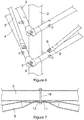
- a fastener assembly in the form of a single elongate fastener (21) having an arcuate intermediate saddle portion (22) engaging a surface of the pylon that is directed outwardly relative to the corner so that the pylon is urged by the fastener assembly into the corner region.
- the saddle portion is formed to closely follow the outer surface of the pylon and the fastener has two straight screw threaded end portions (23) each of which passes through the associated frame member with a nut (24) engaging an outside of the associated frame member.
- the straight end portions extend transversely, typically at almost right angles, relative to the associated frame member.
- the nuts (24) associated with each screw threaded end are such that when tightened, the nuts cause the saddle portion to engage the pylon and lock it axially relative to the frame members in a selected position.
- the surface of the frame members engaged by the pylon are pre-formed to provide a curved contact surface (25) conforming substantially to the outer surface of the pylon that is engaged by the frame member.
- the frame members and brace members are tubular and made of a deformable metal that can be pressed to flatten the ends or a central zone of the brace members and to provide said contact surfaces and flattened perforated ends of the frame members that are bolted together. It is therefore convenient to use galvanised iron or steel in the fabrication of the various components as the only fabrication procedure to be carried out is to cut the lengths at one position and a cut end can be relatively easily provided with adequate corrosion protection, unlike welded zones.
- the adjustment of the axial positions of the individual pylons and intermediate pylons is enabled by the associated fastener assembly that bridges a corner between two joined straight frame or sub-frame members with the pylon firmly clamped between the end regions of the frame members and the fastener.
- the arrangement described above therefore provides a pylon and generally horizontal supporting frame assembly in which the multiple frame members support multiple pylons extending at generally right angles to a plane of the frame assembly, wherein each pylon is height adjustable relative to the plane of the frame assembly and has associated with it a releasable clamping assembly for clamping each pylon such that the pylon and supporting frame assembly is supported on a supporting surface with multiple, and preferably all of the pylons and intermediate pylons having their lowermost ends engaging the supporting surface.
- the physical characteristics of the supporting surface are not particularly suitable in regions where some pylons are to engage the supporting surface and additional accessories such as a base plate (27) or radially extending leg (28) optionally having a sleeve (29) for receiving a laterally offset foot or a ground engaging screw (not shown).
- additional accessories such as a base plate (27) or radially extending leg (28) optionally having a sleeve (29) for receiving a laterally offset foot or a ground engaging screw (not shown).
- the latter are illustrated in Figure 10 .
- each pylon may be adjusted prior to clamping the pylon in a selected vertical position relative to the supporting frame assembly which is carried out by clamping the two vertically spaced fastener assemblies associated with the upper and lower straight frame members in position.
- upper and lower frame members operate as two sides of a parallelogram in contradistinction to the instance in which trusses comprise upper and lower frame members that are firmly and immovably attached to each other by multiple diagonal brace members that are typically welded to the frame members thereby necessitating considerable manual labour and material input and also considerable additional corrosion protection.
- the arrangement of the invention therefore allows for parallel pylons in uneven terrain, something that it is anticipated will be rather valuable for accuracy of items such as heliostats.
- the truss structure is much simpler as there is no welding and accompanying additional corrosion protection required.
- the basic geometry of the frame assembly in plan view can be changed widely and need not be based on a triangle as in the embodiment described above.
- the shape of the frame could be square, rectangular, or of any other polygonal shape such as hexagonal.
Landscapes
- Engineering & Computer Science (AREA)
- General Engineering & Computer Science (AREA)
- Mechanical Engineering (AREA)
- Sustainable Development (AREA)
- Thermal Sciences (AREA)
- Combustion & Propulsion (AREA)
- Physics & Mathematics (AREA)
- Life Sciences & Earth Sciences (AREA)
- Chemical & Material Sciences (AREA)
- Sustainable Energy (AREA)
- Architecture (AREA)
- Structural Engineering (AREA)
- Civil Engineering (AREA)
- Tents Or Canopies (AREA)
- Refuge Islands, Traffic Blockers, Or Guard Fence (AREA)
- Mutual Connection Of Rods And Tubes (AREA)
- Jib Cranes (AREA)
- Road Signs Or Road Markings (AREA)
- Clamps And Clips (AREA)
Claims (10)
- Mât ajustable en hauteur (2, 15) et ensemble d'ossature portante (1), dans lequel l'ensemble inclut au moins un ensemble de fixation, dans lequel l'ossature portante inclut au moins une paire d'éléments d'ossature (3, 4, 16, 17) se rencontrant au niveau d'un coin avec les éléments d'ossature étant globalement co-planaires et le mât étant poussé dans le coin de façon à s'étendre à des angles globalement droits par rapport à un plan incluant les deux éléments d'ossature de ladite au moins une paire d'éléments d'ossature (3, 4, 16, 17), dans lequel l'au moins un ensemble de fixation (21) possède deux parties d'extrémité (23) chacune desquelles est ancrée par rapport à son élément d'ossature associé de façon à s'étendre transversalement par rapport à l'élément d'ossature associé et dans lequel l'ensemble de fixation inclut une partie de sabot intermédiaire (22) en prise avec une surface du mât qui est dirigée vers l'extérieur par rapport au coin de façon à ce que le mât soit poussé par l'ensemble de fixation (21) dans le coin quand l'ensemble de fixation est serré pour de la sorte mettre en prise le mât et le verrouiller axialement par rapport aux éléments d'ossature dans une position sélectionnée, l'ensemble étant caractérisé en ce que la surface des éléments d'ossature mise en prise par un mât soit pré-formée pour fournir une surface de contact (25) se conformant sensiblement à la surface externe du mât et les deux éléments d'ossature de ladite au moins une paire d'éléments d'ossature sont des éléments d'ossature tubulaires constitués d'un métal déformable ou d'un autre matériau approprié qui est formé pour fournir lesdites surfaces de contact (25) et possèdent des extrémités aplaties chevauchées (6) perforées et boulonnées (7) ou rivetées mutuellement au niveau du coin où elles se rencontrent.
- Mât ajustable en hauteur et ensemble d'ossature portante selon la revendication 1, dans lequel chacune des parties d'extrémité de l'ensemble de fixation passent à travers ou autour de l'élément d'ossature associé.
- Mât ajustable en hauteur et ensemble d'ossature portante selon la revendication 1 ou 2, dans lequel une tête ou un écrou (24) met en prise une face extérieure de l'élément d'ossature associé pour l'ancrer par rapport à l'élément d'ossature.
- Mât ajustable en hauteur et ensemble d'ossature portante selon l'une quelconque des revendications précédentes, dans lequel l'ensemble de fixation est une fixation allongée unique (21) possédant une partie de sabot centrale arquée (22) formée pour suivre étroitement la surface externe d'un mât et deux parties d'extrémité droites (23) qui constituent lesdites parties d'extrémité.
- Mât ajustable en hauteur et ensemble d'ossature portante selon l'une quelconque des revendications précédentes, dans lequel l'angle selon lequel les éléments d'ossature se rencontrent mutuellement au niveau du coin est sélectionné parmi un angle droit et un angle aigu.
- Mât ajustable en hauteur et ensemble d'ossature portante selon la revendication 5, dans lequel les éléments d'ossature se rencontrent mutuellement au niveau du coin selon un angle aigu d'environ 60 °.
- Mât ajustable en hauteur et ensemble d'ossature portante selon l'une quelconque des revendications précédentes, dans lequel chacun des éléments d'ossature fait partie de l'une de deux fermes chacune desquelles est composée d'un élément d'ossature droit supérieur (3) et d'un élément d'ossature droit inférieur (4) avec les deux éléments d'ossature droits supérieurs et les deux inférieurs faisant office desdits éléments d'ossature avec chaque ferme ayant des éléments de contrefiches inclinés (5) s'étendant entre les éléments d'ossature droits supérieurs et inférieurs de chaque ferme.
- Mât ajustable en hauteur et ensemble d'ossature portante selon la revendication 7, dans lequel les éléments de contrefiches sont tubulaires ou en section en angle, section en canal, une barre plate avec des extrémités aplaties (8) et une zone centrale aplatie (11) qui sont perforées pour recevoir des boulons (9), rivets ou autres fixations passant à travers celles-ci.
- Mât ajustable en hauteur et ensemble d'ossature portante selon l'une quelconque des revendications 7 ou 8, dans lequel les éléments de contrefiches sont limités en nombre à un élément de contrefiche allongé unique pour chaque travée d'éléments d'ossature entre des mâts adjacents.
- Mât ajustable en hauteur (2, 15) et ensemble d'ossature portante (1) selon l'une quelconque des revendications précédentes, dans lequel l'ensemble (1) inclut de multiples paires de ladite au moins une paire d'éléments d'ossature (3, 4, 16, 17) supportant de multiples mâts (2, 15), dans lequel chaque mât (2, 15) est supporté par l'ossature au niveau de chaque coin défini par lesdites multiples paires d'éléments d'ossature (3, 4, 16, 17) au moyen de l'au moins un ensemble de fixation (21) associé audit élément d'ossature, de sorte que les mâts (2, 15) sont chacun en mesure d'être ajustés en position verticale par rapport à l'ossature pour amener des extrémités inférieures des multiples mâts (2, 15) à mettre en prise une surface de support pour supporter à la fois l'ossature et les mâts supportés par celle-ci.
Applications Claiming Priority (1)
| Application Number | Priority Date | Filing Date | Title |
|---|---|---|---|
| ZA201502201 | 2015-04-07 |
Publications (2)
| Publication Number | Publication Date |
|---|---|
| EP3078923A1 EP3078923A1 (fr) | 2016-10-12 |
| EP3078923B1 true EP3078923B1 (fr) | 2019-06-05 |
Family
ID=55750305
Family Applications (1)
| Application Number | Title | Priority Date | Filing Date |
|---|---|---|---|
| EP16164001.6A Active EP3078923B1 (fr) | 2015-04-07 | 2016-04-06 | Ensemble pylône et cadre de support réglable en hauter |
Country Status (11)
| Country | Link |
|---|---|
| US (1) | US9995427B2 (fr) |
| EP (1) | EP3078923B1 (fr) |
| CN (1) | CN106049957B (fr) |
| AP (1) | AP2016009131A0 (fr) |
| AU (1) | AU2016202007B2 (fr) |
| CL (1) | CL2016000793A1 (fr) |
| ES (1) | ES2744188T3 (fr) |
| IL (1) | IL244977B (fr) |
| MA (1) | MA39619A (fr) |
| MX (1) | MX370445B (fr) |
| TN (1) | TN2016000117A1 (fr) |
Families Citing this family (8)
| Publication number | Priority date | Publication date | Assignee | Title |
|---|---|---|---|---|
| AU2016202006B2 (en) * | 2015-04-07 | 2020-05-21 | Stellenbosch University | Supporting frame assembly |
| CN106766036B (zh) * | 2016-12-22 | 2022-07-12 | 珠海格力电器股份有限公司 | 一种空调机组 |
| GB2573976A (en) * | 2017-09-20 | 2019-11-27 | Edwin Benson Mark | Wind turbine installations |
| CN108532620B (zh) * | 2018-05-22 | 2024-01-30 | 中国电建集团中南勘测设计研究院有限公司 | 一种应用于群桩基础的浇桩框架及浇筑方法 |
| CN110007692B (zh) * | 2019-04-26 | 2022-06-17 | 深圳中科能投能源有限公司 | 一种双推杆旋转机构及定日镜系统 |
| WO2021062391A1 (fr) * | 2019-09-26 | 2021-04-01 | Arizona Board Of Regents On Behalf Of The University Of Arizona | Héliostat léger à focalisation active |
| CN115126222A (zh) * | 2022-06-22 | 2022-09-30 | 中国建筑第二工程局有限公司 | 一种基于三角稳定性的模板支撑架及其施工方法 |
| CN117650743B (zh) * | 2023-10-20 | 2024-09-20 | 希玛科技集团股份有限公司 | 一种光伏发电pack用模块化可控应急供电装置及其控制方法 |
Family Cites Families (59)
| Publication number | Priority date | Publication date | Assignee | Title |
|---|---|---|---|---|
| NL69767C (fr) * | ||||
| US835281A (en) * | 1906-05-31 | 1906-11-06 | Broderick Haskell | Telegraph-pole. |
| US1553800A (en) * | 1920-10-18 | 1925-09-15 | Brandt & Krell Engineering Com | Knockdown pipe derrick |
| US1813373A (en) * | 1929-01-22 | 1931-07-07 | Charles L Wooldridge Inc | Lattice beam |
| US1865059A (en) * | 1929-07-18 | 1932-06-28 | Budd Edward G Mfg Co | Girder construction |
| US2030262A (en) * | 1930-01-27 | 1936-02-11 | Maddock Thomas | Truss or bridge |
| GB525032A (en) * | 1938-02-25 | 1940-08-20 | Safway Steel Scaffolds Co Of A | Improvements in supports for scaffolding members |
| FR982148A (fr) * | 1949-01-13 | 1951-06-04 | Raccord à trois voies pour échafaudages, rayonnages, casiers ou constructions analogues, tubulaires ou en fers cornières, profilés, etc. | |
| US2655394A (en) * | 1949-01-26 | 1953-10-13 | Tubcor Internat | Connection for scaffoldings, shelves, racks, and like structures |
| US2566287A (en) * | 1950-09-16 | 1951-08-28 | Jr Lewis H Finneburgh | Television antenna system |
| US2736613A (en) * | 1952-02-09 | 1956-02-28 | Zigmund J Jagiel | Sectional frame structure |
| US2847237A (en) * | 1953-07-02 | 1958-08-12 | Ackerman Paul Isidor | Coupling for piping sections |
| US2848757A (en) * | 1956-08-15 | 1958-08-26 | Billy J Golden | Knock-down shelter |
| US2906551A (en) * | 1958-08-04 | 1959-09-29 | Tubular Structures Corp Of Ame | Clamping devices |
| US3199815A (en) * | 1961-11-21 | 1965-08-10 | Martinkovic Paul Steve | Universal muffler hanger |
| US3247629A (en) * | 1962-06-05 | 1966-04-26 | Behlen Mfg Company Inc | Catenary roof structure |
| US3318561A (en) * | 1965-05-12 | 1967-05-09 | Antenna Specialists Co | Antenna support bracket |
| US3386222A (en) * | 1966-05-23 | 1968-06-04 | Arthur L. Troutner | High-load truss joist link |
| US3409259A (en) * | 1967-06-19 | 1968-11-05 | Turco Mfg Company | Gym set headbar attachment channel |
| US3564783A (en) * | 1969-08-05 | 1971-02-23 | Fosco Fabricators Inc | Superhighway driver direction structure erectible in the field |
| US3570204A (en) * | 1969-09-24 | 1971-03-16 | Timber Structures Inc | Truss joists |
| US3925942A (en) * | 1973-11-12 | 1975-12-16 | Space Age Ind Inc | Modular structure formed of interconnected tubular members |
| US4094116A (en) * | 1977-06-06 | 1978-06-13 | Simpson Manufacturing Co., Inc. | Web tube with separated end walls |
| US4214841A (en) * | 1977-06-20 | 1980-07-29 | Hayashi Henry T | Clamp-connector for joining three tubular members at corners |
| US4229742A (en) * | 1979-06-18 | 1980-10-21 | Orlando Rotunda | Cubicle Quad antenna |
| US4624599A (en) * | 1984-06-14 | 1986-11-25 | Piasecki Aircraft Corp. | Multi-tubular truss joint and method of joining tube ends |
| US4957186A (en) * | 1989-12-11 | 1990-09-18 | T J International, Inc. | Span-adjustable open-web support bracket |
| US5787673A (en) * | 1992-09-14 | 1998-08-04 | Pirod, Inc. | Antenna support with multi-direction adjustability |
| US5274888A (en) * | 1993-04-05 | 1994-01-04 | Gto, Inc. | Adjustable U-bolt type pipe clamp |
| US5920291A (en) * | 1996-01-22 | 1999-07-06 | Baltimore Gas & Electric Company | Antenna mounting bracket and assembly |
| US5954305A (en) * | 1997-09-09 | 1999-09-21 | Summit Manufacturing, Inc. | Adaptable antenna mounting platform for fixed securement to an elongated mast pole |
| US6225962B1 (en) * | 1998-09-18 | 2001-05-01 | Gabriel Electronics Incorporated | Apparatus and method for an adjustable linkage |
| US6043795A (en) * | 1998-10-02 | 2000-03-28 | Radio Frequency Systems, Inc. | Support system for large antennas, including multi-beam antennas |
| US6561473B1 (en) * | 2001-03-30 | 2003-05-13 | Pirod, Inc. | Universal pipe mounting clamp and assembly |
| US6499266B1 (en) * | 2001-07-16 | 2002-12-31 | Lemar Industries Corp. | Truss construction |
| US6532953B1 (en) * | 2001-08-30 | 2003-03-18 | The Boeing Company | Geometric dome stowable tower reflector |
| PT102751A (pt) * | 2002-04-04 | 2003-10-31 | Antonio Marino Naeff Ferreira | Interface de suporte de antenas |
| US7779599B2 (en) * | 2004-03-31 | 2010-08-24 | Safway Services, Llc | Articulating work platform support system, work platform system, and methods of use thereof |
| US7113145B1 (en) * | 2005-05-23 | 2006-09-26 | Valmont Industries, Inc. | Antenna mounting bracket assembly |
| US7086207B2 (en) * | 2005-06-09 | 2006-08-08 | Andrew Corporation | Antenna sector frame |
| ES2280138B1 (es) * | 2006-02-21 | 2008-08-16 | Er Automatizacion, S.A. | Un sistema dinamico de seguimiento solar. |
| US7466286B2 (en) * | 2006-03-06 | 2008-12-16 | Chapman Brandon M | Folding frame for mounting an antenna |
| US20080053032A1 (en) * | 2006-08-31 | 2008-03-06 | Hockemeyer Timothy J | Support column system for emergency isolation and treatment shelter (EITS) |
| US20080184653A1 (en) * | 2006-10-13 | 2008-08-07 | Bauman Kevin P | Truss Tower Leg Reinforcing System |
| US7659865B2 (en) * | 2007-05-13 | 2010-02-09 | Steelhead Metal & Fab, Llc | Adjustable fast set antenna frame |
| CN101784844B (zh) * | 2007-06-08 | 2014-05-28 | 伊苏勒有限公司 | 用于太阳热能应用的太阳能收集系统 |
| US8397463B2 (en) * | 2009-02-03 | 2013-03-19 | Allred & Associates Inc. | 3-dimensional universal tube connector system |
| US8939143B2 (en) * | 2011-05-09 | 2015-01-27 | Michael Zuritis | Solar array column cap |
| CA2832379A1 (fr) * | 2011-05-24 | 2012-11-29 | Magna International Inc. | Ensemble cadre de support et procede permettant de former un ensemble cadre de support |
| US20130008431A1 (en) * | 2011-07-05 | 2013-01-10 | Google Inc. | Solar Energy Substrate Aerodynamic Flaps |
| JP6040242B2 (ja) * | 2011-08-15 | 2016-12-07 | モーガン ソーラー インコーポレーテッド | 自己安定型の太陽光追尾装置 |
| EP2825827B1 (fr) * | 2012-03-15 | 2017-05-17 | European Space Agency | Structure annulaire de support mécanique |
| CN202706637U (zh) * | 2012-06-28 | 2013-01-30 | 南京开悦科技有限公司 | 一种用于输电线路钢管塔上安装视频监控系统的抱箍支架 |
| US8959868B2 (en) * | 2012-09-17 | 2015-02-24 | Bluescope Buildings North America, Inc. | Truss system |
| PT2917658T (pt) * | 2012-11-09 | 2018-12-12 | Univ Stellenbosch | Sistema de concentração de energia solar que compreende estruturas de suporte para helióstatos múltiplos |
| US20140150845A1 (en) * | 2012-11-30 | 2014-06-05 | Morgan Solar Inc. | Solar tracking apparatus and field arrangements thereof |
| US20140223745A1 (en) * | 2013-02-08 | 2014-08-14 | Davis Eberhart | Bolted Structural Connection Systems |
| CN203603571U (zh) * | 2013-12-05 | 2014-05-21 | 国家电网公司 | 绝缘子支撑门架 |
| AU2016202006B2 (en) * | 2015-04-07 | 2020-05-21 | Stellenbosch University | Supporting frame assembly |
-
2016
- 2016-03-31 AU AU2016202007A patent/AU2016202007B2/en not_active Ceased
- 2016-04-04 TN TN2016000117A patent/TN2016000117A1/en unknown
- 2016-04-06 CL CL2016000793A patent/CL2016000793A1/es unknown
- 2016-04-06 MA MA039619A patent/MA39619A/fr unknown
- 2016-04-06 AP AP2016009131A patent/AP2016009131A0/en unknown
- 2016-04-06 ES ES16164001T patent/ES2744188T3/es active Active
- 2016-04-06 EP EP16164001.6A patent/EP3078923B1/fr active Active
- 2016-04-06 MX MX2016004427A patent/MX370445B/es active IP Right Grant
- 2016-04-07 CN CN201610213477.7A patent/CN106049957B/zh not_active Expired - Fee Related
- 2016-04-07 IL IL244977A patent/IL244977B/en active IP Right Grant
- 2016-04-07 US US15/093,022 patent/US9995427B2/en active Active
Non-Patent Citations (1)
| Title |
|---|
| None * |
Also Published As
| Publication number | Publication date |
|---|---|
| ES2744188T3 (es) | 2020-02-24 |
| TN2016000117A1 (en) | 2017-10-06 |
| MA39619A (fr) | 2016-10-12 |
| US20160298804A1 (en) | 2016-10-13 |
| AU2016202007A1 (en) | 2016-10-27 |
| US9995427B2 (en) | 2018-06-12 |
| IL244977B (en) | 2020-01-30 |
| CL2016000793A1 (es) | 2016-12-02 |
| IL244977A0 (en) | 2016-07-31 |
| CN106049957A (zh) | 2016-10-26 |
| AP2016009131A0 (en) | 2016-04-30 |
| MX370445B (es) | 2019-12-13 |
| CN106049957B (zh) | 2020-08-25 |
| MX2016004427A (es) | 2016-11-24 |
| EP3078923A1 (fr) | 2016-10-12 |
| AU2016202007B2 (en) | 2020-07-09 |
Similar Documents
| Publication | Publication Date | Title |
|---|---|---|
| EP3078923B1 (fr) | Ensemble pylône et cadre de support réglable en hauter | |
| EP3078922B1 (fr) | Ensemble cadre de support | |
| US20110272367A1 (en) | Device for supporting solar modules | |
| US20110163051A1 (en) | Support structure of photovoltaic device | |
| US10128791B2 (en) | Structures and methods for supporting solar panels | |
| US10367443B2 (en) | Systems and methods for supporting solar panels | |
| EP3098539A1 (fr) | Ensemble de support modulaire pour un système d'énergie solaire | |
| KR102647918B1 (ko) | 설치가 용이한 솔라발전시스템 | |
| KR102086572B1 (ko) | 태양광 패널 설치구조 | |
| JP2004124665A (ja) | ソーラーパネル無孔据付架台及びその設置方法 | |
| US6527256B2 (en) | Fence corner and stretch post assembly | |
| US8646230B2 (en) | Flat roof support structure | |
| KR20150004455U (ko) | 안전 난간대 | |
| CN107482998A (zh) | 可调式太阳能支架 | |
| JP2014088708A (ja) | 太陽電池モジュール用の載置架台及び太陽光発電装置 | |
| CN209748456U (zh) | 一种固定单立柱光伏支架 | |
| CN208981526U (zh) | 钢支撑连接固定装置 | |
| AU2024208812B2 (en) | Module for truss web and truss assembly | |
| JP2000154649A (ja) | 仮囲いの方法及びその装置 | |
| CN210439462U (zh) | 一种用于钢结构基础的紧固件 | |
| TR2023015256A2 (tr) | Hizli kolay ve alttan montajli, solar panel konstrüksi̇yon si̇stemi̇ | |
| JP2012112099A (ja) | 鉄骨構造物におけるスプライスプレート | |
| TW202335938A (zh) | 便攜式大型管件輸送機 | |
| JP2016084834A (ja) | 取付金具 | |
| CZ19145U1 (cs) | Pevná i polohovací nosná konstrukce fotovoltaických zařízení |
Legal Events
| Date | Code | Title | Description |
|---|---|---|---|
| PUAI | Public reference made under article 153(3) epc to a published international application that has entered the european phase |
Free format text: ORIGINAL CODE: 0009012 |
|
| 17P | Request for examination filed |
Effective date: 20160406 |
|
| AK | Designated contracting states |
Kind code of ref document: A1 Designated state(s): AL AT BE BG CH CY CZ DE DK EE ES FI FR GB GR HR HU IE IS IT LI LT LU LV MC MK MT NL NO PL PT RO RS SE SI SK SM TR |
|
| AX | Request for extension of the european patent |
Extension state: BA ME |
|
| STAA | Information on the status of an ep patent application or granted ep patent |
Free format text: STATUS: EXAMINATION IS IN PROGRESS |
|
| 17Q | First examination report despatched |
Effective date: 20180801 |
|
| REG | Reference to a national code |
Ref country code: DE Ref legal event code: R079 Ref document number: 602016014687 Country of ref document: DE Free format text: PREVIOUS MAIN CLASS: F24J0002520000 Ipc: F24S0025300000 |
|
| GRAP | Despatch of communication of intention to grant a patent |
Free format text: ORIGINAL CODE: EPIDOSNIGR1 |
|
| STAA | Information on the status of an ep patent application or granted ep patent |
Free format text: STATUS: GRANT OF PATENT IS INTENDED |
|
| RIC1 | Information provided on ipc code assigned before grant |
Ipc: F24S 25/30 20180101AFI20181213BHEP |
|
| INTG | Intention to grant announced |
Effective date: 20190109 |
|
| RIC1 | Information provided on ipc code assigned before grant |
Ipc: F24S 25/30 20180101AFI20181213BHEP |
|
| GRAS | Grant fee paid |
Free format text: ORIGINAL CODE: EPIDOSNIGR3 |
|
| GRAA | (expected) grant |
Free format text: ORIGINAL CODE: 0009210 |
|
| STAA | Information on the status of an ep patent application or granted ep patent |
Free format text: STATUS: THE PATENT HAS BEEN GRANTED |
|
| AK | Designated contracting states |
Kind code of ref document: B1 Designated state(s): AL AT BE BG CH CY CZ DE DK EE ES FI FR GB GR HR HU IE IS IT LI LT LU LV MC MK MT NL NO PL PT RO RS SE SI SK SM TR |
|
| REG | Reference to a national code |
Ref country code: GB Ref legal event code: FG4D |
|
| REG | Reference to a national code |
Ref country code: CH Ref legal event code: EP |
|
| REG | Reference to a national code |
Ref country code: AT Ref legal event code: REF Ref document number: 1140423 Country of ref document: AT Kind code of ref document: T Effective date: 20190615 |
|
| REG | Reference to a national code |
Ref country code: IE Ref legal event code: FG4D |
|
| REG | Reference to a national code |
Ref country code: DE Ref legal event code: R096 Ref document number: 602016014687 Country of ref document: DE |
|
| REG | Reference to a national code |
Ref country code: NL Ref legal event code: MP Effective date: 20190605 |
|
| REG | Reference to a national code |
Ref country code: LT Ref legal event code: MG4D |
|
| PG25 | Lapsed in a contracting state [announced via postgrant information from national office to epo] |
Ref country code: FI Free format text: LAPSE BECAUSE OF FAILURE TO SUBMIT A TRANSLATION OF THE DESCRIPTION OR TO PAY THE FEE WITHIN THE PRESCRIBED TIME-LIMIT Effective date: 20190605 Ref country code: NO Free format text: LAPSE BECAUSE OF FAILURE TO SUBMIT A TRANSLATION OF THE DESCRIPTION OR TO PAY THE FEE WITHIN THE PRESCRIBED TIME-LIMIT Effective date: 20190905 Ref country code: LT Free format text: LAPSE BECAUSE OF FAILURE TO SUBMIT A TRANSLATION OF THE DESCRIPTION OR TO PAY THE FEE WITHIN THE PRESCRIBED TIME-LIMIT Effective date: 20190605 Ref country code: HR Free format text: LAPSE BECAUSE OF FAILURE TO SUBMIT A TRANSLATION OF THE DESCRIPTION OR TO PAY THE FEE WITHIN THE PRESCRIBED TIME-LIMIT Effective date: 20190605 Ref country code: AL Free format text: LAPSE BECAUSE OF FAILURE TO SUBMIT A TRANSLATION OF THE DESCRIPTION OR TO PAY THE FEE WITHIN THE PRESCRIBED TIME-LIMIT Effective date: 20190605 Ref country code: SE Free format text: LAPSE BECAUSE OF FAILURE TO SUBMIT A TRANSLATION OF THE DESCRIPTION OR TO PAY THE FEE WITHIN THE PRESCRIBED TIME-LIMIT Effective date: 20190605 |
|
| PG25 | Lapsed in a contracting state [announced via postgrant information from national office to epo] |
Ref country code: LV Free format text: LAPSE BECAUSE OF FAILURE TO SUBMIT A TRANSLATION OF THE DESCRIPTION OR TO PAY THE FEE WITHIN THE PRESCRIBED TIME-LIMIT Effective date: 20190605 Ref country code: RS Free format text: LAPSE BECAUSE OF FAILURE TO SUBMIT A TRANSLATION OF THE DESCRIPTION OR TO PAY THE FEE WITHIN THE PRESCRIBED TIME-LIMIT Effective date: 20190605 Ref country code: BG Free format text: LAPSE BECAUSE OF FAILURE TO SUBMIT A TRANSLATION OF THE DESCRIPTION OR TO PAY THE FEE WITHIN THE PRESCRIBED TIME-LIMIT Effective date: 20190905 |
|
| REG | Reference to a national code |
Ref country code: AT Ref legal event code: MK05 Ref document number: 1140423 Country of ref document: AT Kind code of ref document: T Effective date: 20190605 |
|
| REG | Reference to a national code |
Ref country code: GR Ref legal event code: EP Ref document number: 20190402698 Country of ref document: GR Effective date: 20191128 |
|
| PG25 | Lapsed in a contracting state [announced via postgrant information from national office to epo] |
Ref country code: RO Free format text: LAPSE BECAUSE OF FAILURE TO SUBMIT A TRANSLATION OF THE DESCRIPTION OR TO PAY THE FEE WITHIN THE PRESCRIBED TIME-LIMIT Effective date: 20190605 Ref country code: CZ Free format text: LAPSE BECAUSE OF FAILURE TO SUBMIT A TRANSLATION OF THE DESCRIPTION OR TO PAY THE FEE WITHIN THE PRESCRIBED TIME-LIMIT Effective date: 20190605 Ref country code: PT Free format text: LAPSE BECAUSE OF FAILURE TO SUBMIT A TRANSLATION OF THE DESCRIPTION OR TO PAY THE FEE WITHIN THE PRESCRIBED TIME-LIMIT Effective date: 20191007 Ref country code: SK Free format text: LAPSE BECAUSE OF FAILURE TO SUBMIT A TRANSLATION OF THE DESCRIPTION OR TO PAY THE FEE WITHIN THE PRESCRIBED TIME-LIMIT Effective date: 20190605 Ref country code: NL Free format text: LAPSE BECAUSE OF FAILURE TO SUBMIT A TRANSLATION OF THE DESCRIPTION OR TO PAY THE FEE WITHIN THE PRESCRIBED TIME-LIMIT Effective date: 20190605 Ref country code: AT Free format text: LAPSE BECAUSE OF FAILURE TO SUBMIT A TRANSLATION OF THE DESCRIPTION OR TO PAY THE FEE WITHIN THE PRESCRIBED TIME-LIMIT Effective date: 20190605 Ref country code: EE Free format text: LAPSE BECAUSE OF FAILURE TO SUBMIT A TRANSLATION OF THE DESCRIPTION OR TO PAY THE FEE WITHIN THE PRESCRIBED TIME-LIMIT Effective date: 20190605 |
|
| REG | Reference to a national code |
Ref country code: ES Ref legal event code: FG2A Ref document number: 2744188 Country of ref document: ES Kind code of ref document: T3 Effective date: 20200224 |
|
| PG25 | Lapsed in a contracting state [announced via postgrant information from national office to epo] |
Ref country code: SM Free format text: LAPSE BECAUSE OF FAILURE TO SUBMIT A TRANSLATION OF THE DESCRIPTION OR TO PAY THE FEE WITHIN THE PRESCRIBED TIME-LIMIT Effective date: 20190605 Ref country code: IS Free format text: LAPSE BECAUSE OF FAILURE TO SUBMIT A TRANSLATION OF THE DESCRIPTION OR TO PAY THE FEE WITHIN THE PRESCRIBED TIME-LIMIT Effective date: 20191005 |
|
| REG | Reference to a national code |
Ref country code: DE Ref legal event code: R097 Ref document number: 602016014687 Country of ref document: DE |
|
| PG25 | Lapsed in a contracting state [announced via postgrant information from national office to epo] |
Ref country code: TR Free format text: LAPSE BECAUSE OF FAILURE TO SUBMIT A TRANSLATION OF THE DESCRIPTION OR TO PAY THE FEE WITHIN THE PRESCRIBED TIME-LIMIT Effective date: 20190605 |
|
| PLBE | No opposition filed within time limit |
Free format text: ORIGINAL CODE: 0009261 |
|
| STAA | Information on the status of an ep patent application or granted ep patent |
Free format text: STATUS: NO OPPOSITION FILED WITHIN TIME LIMIT |
|
| PG25 | Lapsed in a contracting state [announced via postgrant information from national office to epo] |
Ref country code: PL Free format text: LAPSE BECAUSE OF FAILURE TO SUBMIT A TRANSLATION OF THE DESCRIPTION OR TO PAY THE FEE WITHIN THE PRESCRIBED TIME-LIMIT Effective date: 20190605 Ref country code: DK Free format text: LAPSE BECAUSE OF FAILURE TO SUBMIT A TRANSLATION OF THE DESCRIPTION OR TO PAY THE FEE WITHIN THE PRESCRIBED TIME-LIMIT Effective date: 20190605 |
|
| 26N | No opposition filed |
Effective date: 20200306 |
|
| PG25 | Lapsed in a contracting state [announced via postgrant information from national office to epo] |
Ref country code: SI Free format text: LAPSE BECAUSE OF FAILURE TO SUBMIT A TRANSLATION OF THE DESCRIPTION OR TO PAY THE FEE WITHIN THE PRESCRIBED TIME-LIMIT Effective date: 20190605 |
|
| REG | Reference to a national code |
Ref country code: DE Ref legal event code: R119 Ref document number: 602016014687 Country of ref document: DE |
|
| PG25 | Lapsed in a contracting state [announced via postgrant information from national office to epo] |
Ref country code: MC Free format text: LAPSE BECAUSE OF FAILURE TO SUBMIT A TRANSLATION OF THE DESCRIPTION OR TO PAY THE FEE WITHIN THE PRESCRIBED TIME-LIMIT Effective date: 20190605 |
|
| REG | Reference to a national code |
Ref country code: CH Ref legal event code: PL |
|
| PG25 | Lapsed in a contracting state [announced via postgrant information from national office to epo] |
Ref country code: LU Free format text: LAPSE BECAUSE OF NON-PAYMENT OF DUE FEES Effective date: 20200406 Ref country code: DE Free format text: LAPSE BECAUSE OF NON-PAYMENT OF DUE FEES Effective date: 20201103 Ref country code: CH Free format text: LAPSE BECAUSE OF NON-PAYMENT OF DUE FEES Effective date: 20200430 Ref country code: FR Free format text: LAPSE BECAUSE OF NON-PAYMENT OF DUE FEES Effective date: 20200430 Ref country code: LI Free format text: LAPSE BECAUSE OF NON-PAYMENT OF DUE FEES Effective date: 20200430 |
|
| REG | Reference to a national code |
Ref country code: BE Ref legal event code: MM Effective date: 20200430 |
|
| PG25 | Lapsed in a contracting state [announced via postgrant information from national office to epo] |
Ref country code: BE Free format text: LAPSE BECAUSE OF NON-PAYMENT OF DUE FEES Effective date: 20200430 |
|
| GBPC | Gb: european patent ceased through non-payment of renewal fee |
Effective date: 20200406 |
|
| PG25 | Lapsed in a contracting state [announced via postgrant information from national office to epo] |
Ref country code: IE Free format text: LAPSE BECAUSE OF NON-PAYMENT OF DUE FEES Effective date: 20200406 Ref country code: GB Free format text: LAPSE BECAUSE OF NON-PAYMENT OF DUE FEES Effective date: 20200406 |
|
| VS25 | Lapsed in a validation state [announced via postgrant information from nat. office to epo] |
Ref country code: MA Free format text: LAPSE BECAUSE OF FAILURE TO SUBMIT A TRANSLATION OF THE DESCRIPTION OR TO PAY THE FEE WITHIN THE PRESCRIBED TIME-LIMIT Effective date: 20190605 |
|
| PGFP | Annual fee paid to national office [announced via postgrant information from national office to epo] |
Ref country code: GR Payment date: 20210420 Year of fee payment: 6 Ref country code: IT Payment date: 20210430 Year of fee payment: 6 |
|
| PGFP | Annual fee paid to national office [announced via postgrant information from national office to epo] |
Ref country code: ES Payment date: 20210625 Year of fee payment: 6 |
|
| PG25 | Lapsed in a contracting state [announced via postgrant information from national office to epo] |
Ref country code: MT Free format text: LAPSE BECAUSE OF FAILURE TO SUBMIT A TRANSLATION OF THE DESCRIPTION OR TO PAY THE FEE WITHIN THE PRESCRIBED TIME-LIMIT Effective date: 20190605 Ref country code: CY Free format text: LAPSE BECAUSE OF FAILURE TO SUBMIT A TRANSLATION OF THE DESCRIPTION OR TO PAY THE FEE WITHIN THE PRESCRIBED TIME-LIMIT Effective date: 20190605 |
|
| PG25 | Lapsed in a contracting state [announced via postgrant information from national office to epo] |
Ref country code: MK Free format text: LAPSE BECAUSE OF FAILURE TO SUBMIT A TRANSLATION OF THE DESCRIPTION OR TO PAY THE FEE WITHIN THE PRESCRIBED TIME-LIMIT Effective date: 20190605 |
|
| PG25 | Lapsed in a contracting state [announced via postgrant information from national office to epo] |
Ref country code: GR Free format text: LAPSE BECAUSE OF NON-PAYMENT OF DUE FEES Effective date: 20221107 |
|
| REG | Reference to a national code |
Ref country code: ES Ref legal event code: FD2A Effective date: 20230526 |
|
| PG25 | Lapsed in a contracting state [announced via postgrant information from national office to epo] |
Ref country code: IT Free format text: LAPSE BECAUSE OF NON-PAYMENT OF DUE FEES Effective date: 20220406 |
|
| PG25 | Lapsed in a contracting state [announced via postgrant information from national office to epo] |
Ref country code: ES Free format text: LAPSE BECAUSE OF NON-PAYMENT OF DUE FEES Effective date: 20220407 |