EP3079202A1 - Mikrowellenantenne, und verfahren zur generierung erster signale und zur detektierung zweiter signale - Google Patents
Mikrowellenantenne, und verfahren zur generierung erster signale und zur detektierung zweiter signale Download PDFInfo
- Publication number
- EP3079202A1 EP3079202A1 EP15290095.7A EP15290095A EP3079202A1 EP 3079202 A1 EP3079202 A1 EP 3079202A1 EP 15290095 A EP15290095 A EP 15290095A EP 3079202 A1 EP3079202 A1 EP 3079202A1
- Authority
- EP
- European Patent Office
- Prior art keywords
- microwave
- microwave signals
- signals
- frequency band
- detector
- Prior art date
- Legal status (The legal status is an assumption and is not a legal conclusion. Google has not performed a legal analysis and makes no representation as to the accuracy of the status listed.)
- Withdrawn
Links
- 238000000034 method Methods 0.000 title claims description 10
- 230000005540 biological transmission Effects 0.000 claims description 14
- 239000003989 dielectric material Substances 0.000 claims description 5
- 238000004891 communication Methods 0.000 description 13
- 230000005855 radiation Effects 0.000 description 6
- 238000009826 distribution Methods 0.000 description 5
- 238000002955 isolation Methods 0.000 description 5
- 230000033001 locomotion Effects 0.000 description 5
- 230000008901 benefit Effects 0.000 description 4
- 238000005516 engineering process Methods 0.000 description 4
- 230000004308 accommodation Effects 0.000 description 3
- 238000010586 diagram Methods 0.000 description 3
- 230000000694 effects Effects 0.000 description 3
- 239000000758 substrate Substances 0.000 description 3
- 239000004020 conductor Substances 0.000 description 2
- 238000013500 data storage Methods 0.000 description 2
- 230000009977 dual effect Effects 0.000 description 2
- 230000003287 optical effect Effects 0.000 description 2
- 239000004033 plastic Substances 0.000 description 2
- 229920003023 plastic Polymers 0.000 description 2
- 229920000915 polyvinyl chloride Polymers 0.000 description 2
- 239000004800 polyvinyl chloride Substances 0.000 description 2
- 102100026396 ADP/ATP translocase 2 Human genes 0.000 description 1
- RYGMFSIKBFXOCR-UHFFFAOYSA-N Copper Chemical compound [Cu] RYGMFSIKBFXOCR-UHFFFAOYSA-N 0.000 description 1
- 101000718417 Homo sapiens ADP/ATP translocase 2 Proteins 0.000 description 1
- 239000011358 absorbing material Substances 0.000 description 1
- 239000003795 chemical substances by application Substances 0.000 description 1
- 230000001276 controlling effect Effects 0.000 description 1
- 229910052802 copper Inorganic materials 0.000 description 1
- 239000010949 copper Substances 0.000 description 1
- 230000005574 cross-species transmission Effects 0.000 description 1
- 230000001419 dependent effect Effects 0.000 description 1
- 238000006073 displacement reaction Methods 0.000 description 1
- 230000002708 enhancing effect Effects 0.000 description 1
- 238000005530 etching Methods 0.000 description 1
- 239000003000 extruded plastic Substances 0.000 description 1
- 230000006870 function Effects 0.000 description 1
- 238000005286 illumination Methods 0.000 description 1
- 238000009434 installation Methods 0.000 description 1
- 238000004519 manufacturing process Methods 0.000 description 1
- 239000000463 material Substances 0.000 description 1
- 230000015654 memory Effects 0.000 description 1
- 239000002184 metal Substances 0.000 description 1
- 229910052751 metal Inorganic materials 0.000 description 1
- 238000007747 plating Methods 0.000 description 1
- 238000002310 reflectometry Methods 0.000 description 1
- 230000001105 regulatory effect Effects 0.000 description 1
- 230000000630 rising effect Effects 0.000 description 1
- 238000004088 simulation Methods 0.000 description 1
- 238000003860 storage Methods 0.000 description 1
Images




Classifications
-
- H—ELECTRICITY
- H01—ELECTRIC ELEMENTS
- H01Q—ANTENNAS, i.e. RADIO AERIALS
- H01Q19/00—Combinations of primary active antenna elements and units with secondary devices, e.g. with quasi-optical devices, for giving the antenna a desired directional characteristic
- H01Q19/06—Combinations of primary active antenna elements and units with secondary devices, e.g. with quasi-optical devices, for giving the antenna a desired directional characteristic using refracting or diffracting devices, e.g. lens
- H01Q19/062—Combinations of primary active antenna elements and units with secondary devices, e.g. with quasi-optical devices, for giving the antenna a desired directional characteristic using refracting or diffracting devices, e.g. lens for focusing
-
- H—ELECTRICITY
- H01—ELECTRIC ELEMENTS
- H01Q—ANTENNAS, i.e. RADIO AERIALS
- H01Q15/00—Devices for reflection, refraction, diffraction or polarisation of waves radiated from an antenna, e.g. quasi-optical devices
- H01Q15/24—Polarising devices; Polarisation filters
-
- H—ELECTRICITY
- H01—ELECTRIC ELEMENTS
- H01Q—ANTENNAS, i.e. RADIO AERIALS
- H01Q3/00—Arrangements for changing or varying the orientation or the shape of the directional pattern of the waves radiated from an antenna or antenna system
- H01Q3/26—Arrangements for changing or varying the orientation or the shape of the directional pattern of the waves radiated from an antenna or antenna system varying the relative phase or relative amplitude of energisation between two or more active radiating elements; varying the distribution of energy across a radiating aperture
- H01Q3/2658—Phased-array fed focussing structure
Definitions
- the present invention relates to telecommunications, in particular to a microwave antenna, and to a method of generating first microwave signals and a detecting second microwave signals by an antenna.
- Frequency-division duplexing does this by transmitting and receiving at different carrier frequencies.
- the 57-60 GHz sub-band may be used for transmitting and the 61-64 GHz sub-band for receiving. This leaves the 60-61 GHz band in between as a guard band.
- the respective transmit and receive functionalities are provided by two different frequency bands, such as 38 and 60 GHz bands.
- Some microwave antennas are known, for example frequency-division-duplex antennas involving two apertures, one for transmission and one for reception.
- An example of the present invention is a microwave antenna comprising:
- Some embodiments involve transmission and reception with mutually-orthogonal linear polarisations, a common transmit-receive antenna aperture, and separating the transmit and receive antenna beams by a simple polarisation-selective plate within the antenna, so that the plate directs the transmit beam from the respective source and the receive beam to the respective detector.
- the polarisation-selective plate provides for aperture sharing based on polarisation diversity.
- Some embodiments have frequency division duplex (FDD) functionality with a single aperture (but without a diplexer being required).
- FDD frequency division duplex
- an antenna is provided for frequency-division-duplexing millimetre-wave communication links.
- each of the abovementioned generator and detector can be configured as a cluster of feeds, whereby one element produces a beam in the boresight direction and the remaining feeds in the cluster produce a selected number of transmit/receive scanned beams.
- the signals from all feeds in the cluster may be combined using a beam-forming algorithm, for example to effectively counteract the swaying and flexing of the pole on which the antenna is mounted, and, at the same time, to take advantage of beam-forming's capability to increase the antenna gain.
- Some embodiments involve steering scanned beams produced by feeds that are displaced relative to each other in the focal plane of the lens, thereby further enhancing the utility of the antenna.
- the resulting beam steering may be purely electronic, involves no moving parts.
- This beam steering may be achieved by simple beam-forming in the analog domain.
- This beam steering may be autonomous in the sense of being without a feedback loop, and is useful to counteract the swaying and flexing of the antenna mounting pole and take advantage of beam-forming's capability to increase the antenna gain.
- the transmit and receive beams may be steered independently of each other.
- the antenna makes use of multi-beam design, active beam-forming and electronically controlled beam switching.
- Some embodiments include the polarisation-selective plate, the dielectric lens antenna, and beam-steering by feeds displaced in the focal plane of the lens.
- the generator comprises the cluster which comprises multiple microwave signal transmitting feed horns which are controllably- switchable for at least one of transmission beam-steering and transmission beam-forming.
- the detector comprises a cluster comprising multiple microwave signal receiving feed horns which are controllably-switchable for at least one of reception beam-steering and reception beam-forming.
- beam-forming coefficients applied at the generator in transmission beam-forming are determined from those applied at the detector in the reception beam-forming.
- the detector comprises the cluster which comprising multiple microwave signal receiving feed horns which are controllably-switchable for at least one of reception beam-steering and reception beam-forming.
- the first microwave signals are of a first frequency band
- the second microwave signals are of a second frequency band, the first frequency band and second frequency band being different.
- the generator provides the first microwave signals along the axis through the plate to the aperture, and the plate is positioned to allow the first microwave signals to pass along said axis.
- the detector is not on said axis, and the second microwave signals are diverted by the plate at an angle to said axis so as to reach the detector.
- the first frequency band is higher than the second frequency band.
- the detector receives the second microwave signals along the axis through the plate and the aperture, and the plate is positioned to allow the first microwave signals to pass along said axis.
- the generator is not on said axis, and the first microwave signals are diverted by the plate to said axis so as to reach the aperture.
- the first frequency band is lower than the second frequency band.
- the microwave antenna further comprises a lens of dielectric material in the aperture.
- Examples of the present invention also relates to corresponding methods.
- Another example of the present invention relates to a method of generating first microwave signals and detecting second microwave signals by an antenna, in which:
- the aperture can be a reflector or lens, or be built up in the form of an array from a multitude of radiating elements.
- a known frequency division duplex (FDD) communication system can, in principle, use a single antenna aperture, but has the disadvantage that a diplexer is required to separate the transmit and receive (sub-) bands. This disadvantage is even more pronounced when beam-steering is required, since many more diplexers are then needed.
- FDD frequency division duplex
- two apertures i.e. two antennas
- one on either end of the communication link namely one antenna for transmitting and the other for receiving.
- a total of four antennas are needed to provide the FDD functionality.
- This increased number of antennas increases the complexity of the communication system and presents problems of accommodation, volume and mass where unobtrusiveness and low structural loads are required, such as on streetlight posts.
- the inventors realised that it is desirable to have an antenna that would provide FDD capability using a single aperture, as opposed to two apertures, thereby reducing complexity, mass and volume.
- the inventors realised that it is possible to provide transmit and receive beams with mutually-orthogonal polarisations, passed via a shared transmit and receive antenna aperture and separated via a polarisation-selective device within the antenna so that the transmit and receive beams are sent to their respective sources/detectors inside the antenna. In this way, FDD functionality is achieved using a single antenna aperture.
- an antenna with a single antenna aperture can make use of a polarisation-sensitive plate for aperture sharing by polarisation diversity.
- a polarisation-selective plate (as used in gridded parabolic or shaped reflectors used in for example dual gridded reflector antennas) may be positioned in an antenna as a semi-transparent mirror (as used as a beam splitter in for example optical telescopes). The resulting antenna does not need a diplexer to separate the signals nor filters.
- the inventors realised that it is possible to counteract the effects of unintended motions of the antenna, such as caused by wind-induced swaying of the streetlight post on which an antenna is mounted, by using beam-forming to steer the transmit and receive beams.
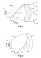
- the antenna ANT includes a single antenna aperture (not shown).
- the aperture is provided with a single dielectric lens 3.
- Two feed clusters 1 of microwave transmit feeds and receive feeds are provided, namely axial feed cluster 1a, which operates with vertical polarisation and side feed cluster 1b, which operates with horizontal polarisation.
- the axial feed cluster 1a is a cluster of transmit feeds and the side feed cluster 1b is a cluster of receive feeds.
- the feeds are feed horns.
- the side feed cluster is a cluster of transmit feeds and axial feed cluster is a cluster of receive feeds.
- transmission and reception is in the same frequency band.
- a polarisation-selective plate 2 positioned between the axial feed cluster 1a and the surface of dielectric lens 3 that is internal to the antenna ANT.
- the plate 2 acts to intercept electromagnetic waves radiated by the axial feed cluster 1a.
- the plate 2 is configured and positioned to be effectively transparent to vertically polarized waves, so as to allow the electromagnetic waves radiated by the axial feed cluster 1a to pass unimpeded; and reflective to horizontally polarised waves so as to direct the received waves from the lens 3 towards the side feed cluster 1b. It can thus be considered that the plate 2 folds the optics of the horizontally polarised electromagnetic waves to the side feed cluster 1b.
- the respective lens-centre and lens-rim rays are indicated. Specifically, from the axial feed cluster 1a the lens-centre ray is marked 11x and the lens-rim rays are marked as 11y and 11z. Similarly, to the side feed cluster 1b the lens-centre ray is marked 12x and the lens-rim rays are marked as 12y and 12z.
- the polarisation-selective plate 2 Since the polarisation-selective plate 2 is inclined by 45° with respect to the lens- centre ray 12x radiated by the side feed cluster 1b, the polarisation-selective plate 2 folds the optics of the electromagnetic rays emanating from the side feed cluster 1b by 90°.
- the polarisation-selective plate 2 is, by way of analogy, positioned like the semitransparent mirror acting as a beam splitter in optical telescopes but functions like the gridded parabolic or shaped reflector used in dual gridded reflector antennas
- Figure 3 shows the back view of a portion of the polarisation-selective plate 2.
- the plate 2 consists of a substantially regular parallel grid of thin electrically conducting strips 5 supported by a low-loss microwave substrate 4.
- the strips are mounted on the substrate 4 on the side of the plate that faces towards the lens 3. (In an alternative embodiment (not shown) the strips are instead mounted on the substrate on the side of the plate that faces the axial cluster.)
- the strips 5 are laid out horizontally, i.e. so as to be co-polarized with the electromagnetic waves.
- the width of the strips and their spacing are carefully selected.
- the strip width is selected to be not so large as to reduce the electromagnetic transparency of the polarisation-selective plate 2 for vertically polarized (cross-polarized) electromagnetic waves in a given frequency band; and also not so narrow that the strips 5 would pose an appreciable inductance to the surface currents induced in the strips by co-polarized electromagnetic waves.
- the strip spacing is selected from within a range of what would be acceptable. In contrast, on the one hand, too large a spacing would cause co-polarized electromagnetic waves to not be properly reflected. On the other hand, too small a spacing would lead to a reduced transparency for cross-polarized electromagnetic waves.
- the polarisation-selective plate 2 is manufactured by conventional manufacturing techniques, in this example using known printed-circuit board technology, whereby a grid of parallel traces is etched in a suitable microwave laminate, e.g., Rogers RT/duroid 5880.
- the axial feed cluster and side feed cluster operate at different frequency bands, in which case, it is generally preferred to assign the lower band to the side feed cluster.
- the axial feed cluster and the side feed cluster are required to operate in different frequency bands, for example the 60- and 38-GHz frequency bands
- the spacing of the strips in the polarisation-selective plate is larger than the other way around, thereby posing less obstruction for cross-polarized electromagnetic waves, i.e., the waves radiated by the axial feed cluster. Accordingly, unnecessary reduction is avoided of the electromagnetic transparency of the polarisation-selective plate for the electromagnetic waves radiated by the axial feed cluster.
- the polarisation-selective plate 2 is particularly well suited for the lens 3.
- the see-through nature of lenses eliminates aperture blockage, allowing for a compact accommodation of the polarisation-selective plate 2 and a direct connection of the feed clusters 1a, 1b to the transmitter/receiver (not shown), eliminating the need to use lossy transmission lines to connect to the transmitter/receiver.
- the volume of free space between the lens 3 and the feed clusters 1a, 1b that effectively serves as the signal distribution network for the lens also allows for an unproblematic accommodation of the polarisation-selective plate 2.
- the lens 3 has its two surfaces shaped by a designer so as to control both the amplitude and phase field distributions in the lens aperture (not shown). This is in contrast to a reflector, which offers only one surface to shape giving less control over the amplitude and phase field distribution in the lens aperture.
- a dielectric lens is one option, for example lens 3 is a dielectric lens in the example shown in Figures 1 and 2 .
- another option is a waveguide lens at millimetre-wave frequencies built up from open-ended waveguides of sub-wavelength cross-sections.
- the axial and side feed clusters 1a and 1b are located in the respective axial and side focal planes of the lens 3, whereby the side focal plane is that provided by the polarisation-selective plate 2.
- each of the feed clusters 1a, 1b consists of seven sources that are feed horns 6 of circular cross-section.
- the feed horns 6 are of the dual-mode type, utilizing the TE 11 and TM 11 field modes, for circular symmetry of the co-polarized beam and low cross-polarized radiation.
- the seven feed horns 6 in each focal plane are spaced so as to produce seven partially overlapping beams 7 when projected into the azimuth-elevation plane.
- the beam layout has a hexagonal boundary.
- the coverage contours shown in Figure 4 correspond to the antenna gain levels 3-4 dB below peak.
- the centre feed horn 8 in each feed cluster provides the boresight beam 9, while the scanned beams are produced by the virtue of relative displacement of the feed horns 6 from the centre feed horn 8 in the focal plane of the lens.
- each of the feed clusters is a feed cluster of transmission sources or receivers, where for example sources/receivers in a cluster together provide a transmission/reception beam in the boresight direction.
- the sources/receivers separately provide scanned beams that can be selected between. This is done by combining the signals from selected sources/receivers under the control of a beam-steering/beam-forming controller that uses a beam-steering/beam-forming algorithm. This is useful, for example not only to counteract the movement, such as swaying of the pole on which the antenna is mounted, but also to make use of beam-forming to provide beams of increased antenna gain, namely transmission gain or reception gain.
- an antenna can be provided for FDD millimetre-wave communication links that has sufficient beam-steering capability to counteract the variations in antenna orientation in practical installations.
- the use of the polarisation-sensitive plate may be seamlessly integrated with beam steering utilizing scanned beams produced by feed clusters and displaced in the focal plane of the lens.
- the resulting beam steering is purely electronic, i.e., involves no moving parts; the beam steering is achieved by simple beam-forming in the analog domain.
- This beam-forming is used to both autonomously (i.e., without a feedback loop) counteract the swaying and flexing of the pole on which the antenna is mounted, and, in addition, take advantage of beam-forming's capability to increase the antenna gain.
- the resulting antenna makes use of active beam-forming and electronically-controlled switching/steering among beams whilst being of small size.
- the transmit and receive beams may be steered independently of each other.
- the feed cluster 1a consists of seven sources 6.
- each of the feed horns 6 provides a corresponding beam 7. Beam-steering is then achieved by dynamically switching between the beams 7 in such a way that one beam at a time is operating.
- a more-advanced way to perform beam steering involves beam-forming.
- an analog beam-former (not shown) is employed to combine signals of all seven feeds to sequentially synthesize nineteen preset beams, whose 3-4 dB below-peak coverage contours are shown in Figure 5 .
- FIG. 6 illustrates a possible hardware implementation of beam-forming on receive, utilizing a monolithic microwave integrated circuit (MMIC).
- MMIC monolithic microwave integrated circuit
- a corresponding MMIC on transmit (not shown) employs gain-controlled power amplifiers instead of low-noise amplifiers.
- beam-forming which is the technology enabler for the beam-steering capability of the antenna, is possible by virtue of having feed clusters, as opposed to just having a single feed.
- each feed cluster acts to, on receive, combine the power received by the seven feed horns and , on transmit, distribute the transmitted power among seven feed horns.
- this distribution is accomplished by means of power dividers 16 (these are indicated in Figure 6 as the “forks" on the left-hand side showing the power-division ratios, e.g., 1:6) and attenuators 18.
- each beam feed cluster needs to also have the capability of controlling the phase of the 7 signals. This is accomplished by means of phase shifters 20.
- FIG. 6 there is a receiver feedback line 21 between a receiver 19 and a control unit 17.
- the power level of the signal received at the receiver 19 is fed to the control unit 17 which regularly switches among the nineteen sets of beam-forming phase and amplitude settings that correspond to the nineteen synthesised beams shown on Figure 5 , to select the set of settings of amplitude (on attenuators 18) and phase (on phase shifters 20) that yields the strongest received signal at that time
- the MMIC is located on the rear side of each feed cluster.
- the MMIC is miniaturized and manufactured in a single integrated assembly for use at millimetre-wave frequencies.
- the MMIC shown in Figure 6 interfaces to the backs of the feed clusters 1a' and 1b' that are shown in Figure 10 .
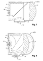
- FIG. 7 Another example antenna ANT2 is shown in Figures 7 to 10 .
- the antenna was designed for the 60-GHz band.
- the lens 3' has the diameter of 90 mm, a focal length of 134 mm, and is made of Rexolite (which has a relative dielectric constant of 2.54 and loss tangent of 0.0001 in the 60-GHz band).
- any low-loss dielectric material with a relative dielectric constant between approximately 2 and 4 may be used in place of Rexolite.
- the polarisation-selective plate 2' is made of the Rogers RT/duroid 5880 laminate.
- the metallic lines of the plate's conductor grid are spaced apart by 0.375 mm and measure 0.075 mm in width. Lines of these dimensions are realized by conventional etching techniques on a 0.25-oz. copper plating.
- Each of the feed clusters 1a', 1b' includes seven feed horns and is produced as an integrated plastic injection-moulded unit or assembly, either metalized or metal-loaded.
- the polarisation-selective plate 2' and the dielectric lens 3' there is an enclosure (or housing) 4' and an RF-absorbing liner 5' on the inside surface of the enclosure 4'.
- the RF-absorbing liner is not provided.
- the enclosure 4' serves two main purposes: Firstly, the enclosure 4' holds the functional components of the antenna in place and, secondly, the enclosure protects the inside volume of the antenna from wind, rain etc.
- the enclosure 4' is made of a dielectric material, namely an extruded plastic pipe, such as of PVC (polyvinyl chloride).
- PVC polyvinyl chloride
- Such plastic pipes by their nature of not having been designed for microwave applications, tend to be lossy at microwave and millimetre-wave frequencies, which benefits the proposed antenna, since an enclosure 4' made of a lossy dielectric material reduces the lens-aperture spillover radiation from the feed clusters 1a', 1b'.
- the optional RF-absorbing liner 5' is made of a conventional absorbing material suitable for absorbing millimetre-wave frequencies and may cover the inside surface of the enclosure 4' partly or fully.
- the enclosure is made of an electrically conductor material, in which case, an RF-absorbing liner 5' becomes necessary in most applications.
- the port-to-port isolation within each of the two feed clusters is better than 30 dB across the 60-GHz band.
- the port-to-port isolation between any one of the seven ports of the axial feed cluster and any one of the seven ports of the side feed cluster, in other words polarisation isolation is better than 45 dB across the 60-GHz band.
- the polarisation isolation performance may be further improved by employing additional polarisation-selective plates (not shown), such as in front of the axial and side feed clusters.
- Figure 11 shows a plot of typical elevation-plane co-polarized far-field gain radiation pattern cross-sections when RF power is applied to the centre feed of the axial feed cluster 1a' (solid line) and the centre feed of the side feed cluster 1b' (dashed line). Note the elevation plane is that of the cross-sectional view shown in Figure 7 .
- the main lobes of both pattern cross-sections are, for practical engineering purposes, effectively identical, which confirms that the polarisation-selective plate 2' works as intended, yielding balance between transparency for the vertically polarized signals radiated by the axial feed cluster 1a' and reflectivity for the horizontally polarized signals radiated by the side feed cluster 1b'.
- Figure 12 shows a plot of typical elevation-plane co-polarized far-field gain radiation pattern cross-sections when beam-forming is used to synthesize beams:
- the polarisation isolation performance may be further improved by employing additional polarisation-selective plates (not shown), such as in front of the axial and side feed clusters.
- the transmit and receive beams may be steered independently of each other.
- program storage devices e.g., digital data storage media, which are machine or computer readable and encode machine-executable or computer-executable programs of instructions, wherein said instructions perform some or all of the steps of said above-described methods.
- the program storage devices may be, e.g., digital memories, magnetic storage media such as a magnetic disks and magnetic tapes, hard drives, or optically readable digital data storage media.
- Some embodiments involve computers programmed to perform said steps of the above-described methods.
Landscapes
- Variable-Direction Aerials And Aerial Arrays (AREA)
Priority Applications (1)
| Application Number | Priority Date | Filing Date | Title |
|---|---|---|---|
| EP15290095.7A EP3079202A1 (de) | 2015-04-10 | 2015-04-10 | Mikrowellenantenne, und verfahren zur generierung erster signale und zur detektierung zweiter signale |
Applications Claiming Priority (1)
| Application Number | Priority Date | Filing Date | Title |
|---|---|---|---|
| EP15290095.7A EP3079202A1 (de) | 2015-04-10 | 2015-04-10 | Mikrowellenantenne, und verfahren zur generierung erster signale und zur detektierung zweiter signale |
Publications (1)
| Publication Number | Publication Date |
|---|---|
| EP3079202A1 true EP3079202A1 (de) | 2016-10-12 |
Family
ID=54207427
Family Applications (1)
| Application Number | Title | Priority Date | Filing Date |
|---|---|---|---|
| EP15290095.7A Withdrawn EP3079202A1 (de) | 2015-04-10 | 2015-04-10 | Mikrowellenantenne, und verfahren zur generierung erster signale und zur detektierung zweiter signale |
Country Status (1)
| Country | Link |
|---|---|
| EP (1) | EP3079202A1 (de) |
Cited By (2)
| Publication number | Priority date | Publication date | Assignee | Title |
|---|---|---|---|---|
| CN112164885A (zh) * | 2020-08-24 | 2021-01-01 | 西安空间无线电技术研究所 | 一种基于多馈源合成网络的幅相优化设计方法 |
| RU2782177C2 (ru) * | 2017-03-17 | 2022-10-21 | Изотропик Системс Лтд | Линзовая антенная система |
Citations (4)
| Publication number | Priority date | Publication date | Assignee | Title |
|---|---|---|---|---|
| GB767531A (en) * | 1954-06-09 | 1957-02-06 | Marconi Wireless Telegraph Co | Improvements in or relating to polarised radio mirrors |
| FR2538959A1 (fr) * | 1983-01-04 | 1984-07-06 | Thomson Csf | Lentille hyperfrequence bi-bande, son procede de fabrication et antenne radar bi-bande de poursuite |
| EP0683541A1 (de) * | 1994-05-17 | 1995-11-22 | SPACE ENGINEERING S.p.A. | Reflektor- oder Linsenantenne mit Strahlablenkung oder -formung |
| WO2009151819A1 (en) * | 2008-06-11 | 2009-12-17 | Lockheed Martin Corporation | Horn antenna and system for transmitting and/or receiving radio frequency signals in multiple frequency bands |
-
2015
- 2015-04-10 EP EP15290095.7A patent/EP3079202A1/de not_active Withdrawn
Patent Citations (4)
| Publication number | Priority date | Publication date | Assignee | Title |
|---|---|---|---|---|
| GB767531A (en) * | 1954-06-09 | 1957-02-06 | Marconi Wireless Telegraph Co | Improvements in or relating to polarised radio mirrors |
| FR2538959A1 (fr) * | 1983-01-04 | 1984-07-06 | Thomson Csf | Lentille hyperfrequence bi-bande, son procede de fabrication et antenne radar bi-bande de poursuite |
| EP0683541A1 (de) * | 1994-05-17 | 1995-11-22 | SPACE ENGINEERING S.p.A. | Reflektor- oder Linsenantenne mit Strahlablenkung oder -formung |
| WO2009151819A1 (en) * | 2008-06-11 | 2009-12-17 | Lockheed Martin Corporation | Horn antenna and system for transmitting and/or receiving radio frequency signals in multiple frequency bands |
Cited By (2)
| Publication number | Priority date | Publication date | Assignee | Title |
|---|---|---|---|---|
| RU2782177C2 (ru) * | 2017-03-17 | 2022-10-21 | Изотропик Системс Лтд | Линзовая антенная система |
| CN112164885A (zh) * | 2020-08-24 | 2021-01-01 | 西安空间无线电技术研究所 | 一种基于多馈源合成网络的幅相优化设计方法 |
Similar Documents
| Publication | Publication Date | Title |
|---|---|---|
| US12142844B2 (en) | Lens antenna system | |
| EP2724418B1 (de) | Strahlformung von hf-speiseenergie für reflektorbasierte antennen | |
| EP2297818B1 (de) | Antennenarray mit metamateriallinse | |
| JP7025859B2 (ja) | 誘電体レンズを用いたステアラブルアンテナアセンブリ | |
| JP6490422B2 (ja) | 蛇行導波路を利用して二重偏波信号を生成するためのアンテナアレイシステム | |
| US8743004B2 (en) | Integrated waveguide cavity antenna and reflector dish | |
| CN102110884B (zh) | 采用无源加载方式控制副瓣电平的有源相控阵天线 | |
| WO2008061107A2 (en) | Antenna | |
| CN101479887A (zh) | 集成波导管天线和阵列 | |
| KR20220131340A (ko) | 향상된 무선 통신 커버리지 영역을 위한 반사어레이 안테나 | |
| CN110444851A (zh) | 多波束偏置馈源反射面天线 | |
| US6690333B2 (en) | Cylindrical ray imaging steered beam array (CRISBA) antenna | |
| JP3813581B2 (ja) | アンテナ装置 | |
| Brandão et al. | FSS-based dual-band cassegrain parabolic antenna for RadarCom applications | |
| EP0100466B1 (de) | Antennensystem für zwei Frequenzbereiche vom Cassegraintyp | |
| CN110571530A (zh) | 一种集成反射阵的可重构抛物面天线 | |
| CA3160748C (en) | Multibeam antenna | |
| US7688268B1 (en) | Multi-band antenna system | |
| EP3079202A1 (de) | Mikrowellenantenne, und verfahren zur generierung erster signale und zur detektierung zweiter signale | |
| CN113346230A (zh) | 一种波束自由偏转的平面微带天线阵列 | |
| CN110649397A (zh) | 一种集成反射阵的可重构平面反射阵天线 | |
| JPH05275920A (ja) | 鏡面修正アンテナ | |
| O'Kane et al. | Circularly polarized curl antenna lens with manual tilt properties | |
| TWI587577B (zh) | Reflective array antenna structure | |
| CN210074129U (zh) | 多波束偏置馈源反射面天线 |
Legal Events
| Date | Code | Title | Description |
|---|---|---|---|
| PUAI | Public reference made under article 153(3) epc to a published international application that has entered the european phase |
Free format text: ORIGINAL CODE: 0009012 |
|
| AK | Designated contracting states |
Kind code of ref document: A1 Designated state(s): AL AT BE BG CH CY CZ DE DK EE ES FI FR GB GR HR HU IE IS IT LI LT LU LV MC MK MT NL NO PL PT RO RS SE SI SK SM TR |
|
| AX | Request for extension of the european patent |
Extension state: BA ME |
|
| 17P | Request for examination filed |
Effective date: 20170412 |
|
| RBV | Designated contracting states (corrected) |
Designated state(s): AL AT BE BG CH CY CZ DE DK EE ES FI FR GB GR HR HU IE IS IT LI LT LU LV MC MK MT NL NO PL PT RO RS SE SI SK SM TR |
|
| STAA | Information on the status of an ep patent application or granted ep patent |
Free format text: STATUS: THE APPLICATION IS DEEMED TO BE WITHDRAWN |
|
| 18D | Application deemed to be withdrawn |
Effective date: 20170413 |