EP3079477B1 - Kombination einer fördervorrichtung für schlachttiere und einer beseitigungsvorrichtung sowie verfahren zum betrieb solch einer kombination - Google Patents
Kombination einer fördervorrichtung für schlachttiere und einer beseitigungsvorrichtung sowie verfahren zum betrieb solch einer kombination Download PDFInfo
- Publication number
- EP3079477B1 EP3079477B1 EP14828324.5A EP14828324A EP3079477B1 EP 3079477 B1 EP3079477 B1 EP 3079477B1 EP 14828324 A EP14828324 A EP 14828324A EP 3079477 B1 EP3079477 B1 EP 3079477B1
- Authority
- EP
- European Patent Office
- Prior art keywords
- pusher element
- active position
- groove
- slaughter
- held part
- Prior art date
- Legal status (The legal status is an assumption and is not a legal conclusion. Google has not performed a legal analysis and makes no representation as to the accuracy of the status listed.)
- Active
Links
Images




Classifications
-
- A—HUMAN NECESSITIES
- A22—BUTCHERING; MEAT TREATMENT; PROCESSING POULTRY OR FISH
- A22C—PROCESSING MEAT, POULTRY, OR FISH
- A22C21/00—Processing poultry
- A22C21/0053—Transferring or conveying devices for poultry
-
- A—HUMAN NECESSITIES
- A22—BUTCHERING; MEAT TREATMENT; PROCESSING POULTRY OR FISH
- A22C—PROCESSING MEAT, POULTRY, OR FISH
- A22C21/00—Processing poultry
- A22C21/0007—Poultry shackles
-
- A—HUMAN NECESSITIES
- A22—BUTCHERING; MEAT TREATMENT; PROCESSING POULTRY OR FISH
- A22C—PROCESSING MEAT, POULTRY, OR FISH
- A22C21/00—Processing poultry
- A22C21/0046—Support devices
Definitions
- the present invention relates to a combination of a conveying device for conveying slaughter animals suspended from product carriers of the conveying device, during which conveyance the slaughter animals describe a path, and a removing device disposed along said path for removing selected slaughter animals from the product carriers,
- the conveying device comprising a guide extending along a transport path, product carriers for the slaughter animals, which are movable in a direction of movement along the guide, each product carrier comprising at least one groove inclined according to a direction of inclination for holding at least one held part of a slaughter animal therein, wherein the at least one groove has an open upper end and a lower end and is laterally oriented relative to the conveying device, at least at the location of the removing device, the removing device comprising a pusher element, moving means for moving the pusher element to and fro between a passive position, in which the pusher element is located outside the path of slaughter animals, and an active position, in which the pusher element is located in the path of at least one held part of a selected slaughter animal in
- slaughterhouses where slaughter animals suspended from product carriers of a conveying device are processed, there is a continuous pursuit of increasing the capacity.
- Modern slaughter lines for slaughter birds are capable of processing typically at least 12,000 birds per hour, for example, but even higher capacities are considered to be desirable with a view to reducing the cost involved in the processing of slaughter birds.
- Various possibilities, whether or not in combination with each other, are available for increasing the capacity of a slaughterhouse.
- a first possibility is to increase the speed of the conveying device by means of which the slaughter animals are conveyed through a slaughterhouse, during which conveyance the slaughter animals are processed.
- a second possibility is to reduce the pitch between successive product carriers.
- slaughterhouses it may for several reasons be necessary to selectively remove slaughter animals, such as birds, from a product carrier at the location of a processing position.
- selective indicates that only selected slaughter animals are to be removed from the product carrier at the location of the processing position, whilst for example the slaughter animals in an adjacent upstream product carrier and an adjacent downstream product carrier must not be removed from said product carrier at the location of said processing position.
- Such a selection may for example take place on the basis of the weight of the slaughter animal or on the basis of a visual assessment of a slaughter animal.
- a transfer situation may occur, in which a slaughter animal is transferred from one product carrier to another product carrier.
- specific slaughter animals may fall from a product carrier into a collecting bin or onto a further conveyor, such as a belt conveyor.
- the grooves it is also conceivable to dimension and/or configure the grooves to have a slight local constriction of the width of the grooves, so that the held parts, such as typically a bird's legs in the case of birds, are held in the lower end of a groove with a slight clamping fit and/or a more or less form-locked fit.
- European publication EP 1 922 935 A1 describes a combination according to the introduction, wherein the moving means comprise a stepping motor or a servomotor and wherein it is possible to impart a movement or speed pattern to the pusher element, which is claimed to make the combination more suitable for high-speed operation. Apart from the fact that this is a relatively costly solution, the magnitude of the positive effect that may be achieved is moreover limited.
- the object of the invention is to provide a solution or at least an improvement as regards such problems.
- the invention provides a combination as described in the introduction, wherein the removing device comprises a further pusher element as well as further moving means for moving the further pusher element to and fro between a further passive position, in which the further pusher element is located outside the path of slaughter animals, and a further active position, in which the further pusher element is located in the path of the at least one held part of the selected slaughter animal in said further active position, or at least during its movement from the further passive position to the further active position, for pushing the at least one held part of the selected slaughter animal from the lower end, in the direction of the upper end, to an intermediate position, wherein the pusher element is designed to push the at least one held part of a slaughter animal from the intermediate position, via the upper end of the at least one groove of a product carrier, out of said at least one groove in the active position or during its movement from the passive position to the active position.
- a further pusher element in combination with a pusher element that is known per se, creates the possibility that initially the at least one held part is pushed from the lower end of the at least one slot in the direction of, but not as far as, the upper end of the at least one slot, after which the pusher element will push the at least one held part from the position of the at least one held part in the at least one slot effected by the further pusher element past the upper end of the at least one slot, and thus out of the at least one slot.
- the advantage of using a further pusher element may be that the pusher element will need less force for pushing the at least one held part of a slaughter animal, such as a bird's legs, past the upper end of the at least one slot, so that there will be a decreased risk of damage to the slaughter animal.
- the advantage of using a further pusher element may also be that as soon as the further pusher element has pushed the at least one held part of the slaughter animal out of the lower end of the at least one slot, and a first part of the movement of the at least one held part that is needed for removing the slaughter animal from the product carrier has thus been carried out, and preferably as soon as the pusher element subsequently comes into contact with the at least one held part or at least with one held part in the case of two or more held parts, the further pusher element can be moved back to the further passive position.
- the risk of a slaughter animal in an adjacent upstream product carrier undesirably coming into contact with the further pusher element can thus be considerably reduced, in spite of the fact that the pusher element is still engaged in pushing the at least one held part of the slaughter animal out of the at least one slot, and in spite of the fact that a relatively high line speed and/or a small pitch between the product carriers is/are used.
- the pusher element need not move from the passive position to the active position until the further pusher element has been moved to the active position. This, too, reduces the risk of a slaughter animal in an adjacent downstream product carrier undesirably coming into contact with the pusher element.
- such a pivot axis may extend parallel to the direction of movement.
- pushing the legs of a slaughter animal of the slots of the product carrier in lateral direction relative to the conveying direction can take place in that the pusher element exerts an impact load on the at least one held part.
- the movement of the at least one held part in the direction of the open end of the at least one slot is thus obtained during movement of the pusher element from the passive position to the active position.
- the pivot axis extends at least substantially perpendicular to the direction of movement.
- the pusher element will in that case function as a guide element, which urges the at least one held part of the slaughter animal sideways in the direction of and past the open end of the at least one slot.
- pivot axis moreover extends perpendicular to, at least substantially so, the direction of inclination, it will be easy to effect a situation in which the pusher element moves closely past the bottom side of the at least one slot, for example at a distance of at most 5 cm, or even more preferably at most 2 cm, upon pivoting between the passive position and the active position. This is advantageous with a view to reducing moments that act on the at least one held part when the slaughter animal is pushed sideways by the pusher element.
- the additional advantage will be that the risk of a next slaughter animal undesirably colliding with the pusher element is further reduced and/or that the magnitude of the pivot angle between the passive position and the active position can be relatively small.
- the invention can in particular, but not exclusively, be used advantageously if the direction of inclination includes an angle that ranges between 40 degrees and 50 degrees with a horizontal line.
- the at least one groove will in that case extend at a relatively steep angle, as a result of which the product carriers in question can be suitable for being operated at a relatively high line speed, for example of 18,000 slaughter animals per hour.
- the further pusher element may be pivotable about a further pivot axis between the further passive position and the further active position, which may be advantageous also for reasons of constructional simplicity.
- the further pivot axis may also be advantageous for the further pivot axis if the further pivot axis extends at least substantially perpendicular to the conveying direction and furthermore preferably at least substantially perpendicular to the direction of inclination.
- the further pusher element in the further passive position thereof, is located at least partially upstream of the pusher element in the passive position thereof.
- the pusher element, at least in the active position thereof, and/or the further pusher element, in the further active position thereof is/are designed for laterally guiding the at least one held part of a selected slaughter animal in the direction of the open end of the at least one groove of a product carrier during transport of the slaughter animal in the direction of movement, to which end the pusher element and/or the further pusher element comprise a guide surface and/or a further guide surface, respectively, wherein, seen in top plan view, the guide surface and/or the further guide surface include(s) an acute angle with the conveying direction in the active position and/or the further active position, respectively, it is possible to obtain the advantage that the mechanical load exerted on the slaughter animal, more specifically on the at least one held part thereof, upon removal of the slaughter animal from the product carrier will be limited.
- the additional advantage is moreover the fact that contact between the pusher element or the further pusher element and a non-selected slaughter animal suspended from a next (upstream) product carrier need not directly result in
- An effective removal of a slaughter animal from a product carrier can be obtained in particular if the pusher element, in the active position thereof, and the further pusher element, in the further active position thereof, are designed for laterally guiding the at least one held part of a selected slaughter animal, wherein the angle which the guide surface includes with the conveying direction is larger than the angle which the further guide surface includes with the conveying direction.
- the speed at which a slaughter animal is pushed sideways by the further pusher element will initially be lower than at a later stage, when the slaughter animal is pushed sideways by the pusher element.
- Said larger angle has the advantage that the legs are pushed out of the slots more quickly, and thus within a relatively shorter conveying length, by the pusher element in comparison with the further pusher element, which need not be problematic if the configuration of the slots makes it possible that the legs are moved through the slots by the pusher element with less resistance than the resistance that the legs experience upon being moved through the slots by the further pusher element.
- the reason for this may be that the slots diverge in the direction of the upper ends and/or that only the lower ends of the legs are held in the slots with a slight clamping fit or in a more or less form-locked manner.
- the pusher element comprises a guide surface as well as a connecting surface that joins the guide surface on the upstream side of the guide surface, which connecting surface, seen in top plan view in the active position of the pusher element, includes an angle with the conveying direction which is larger than the angle which the guide surface includes with the conveying direction.
- the invention is quite suitable, but not exclusively so, for use in transferring slaughter animals from one product carrier to another product carrier, which will usually be of a different type.
- the slaughter line will comprise further product carriers which are movable along a further conveying path, which further product carriers are designed for taking over the slaughter animals whose at least one held part is being pushed out of the at least one groove by the pusher element via the upper end of the at least one groove of a product carrier.
- each product carrier comprises two grooves. In said two grooves, the legs, being the held parts of the slaughter words, can be received.
- the moving means and the further moving means may to that end comprise a control unit, such as a PLC control unit, for example, but a purely mechanical solution, for example using a cam disc, is also conceivable.
- a control unit such as a PLC control unit
- a purely mechanical solution for example using a cam disc, is also conceivable.
- the invention makes it possible for the further pusher element to have returned to the further passive position, thus providing space for a next slaughter animal, while the pusher element is still in the active position and is operative for completely pushing the at least one held part of a slaughter animal out of the at least one slot of a product carrier, making it possible to use relatively high line speeds or a relatively small pitch between adjacent product carriers.
- the invention further provides a method for operating a combination of a conveying device and a removing device according to the invention as described in the foregoing.
- the method comprises the steps of
- step D it is possible to carry out step D after step C, which can be an advantage is in particular if both the further pusher element and the pusher element function as guide means for pushing a bird's legs laterally out of the slots.
- the length of the time interval between steps A and C and/or the length of the time interval between steps B and D is at most 80%, more preferably at most 75%, of the length of the time interval between steps A and D.
- the more the above percentage decreases the greater the advantages of the invention as regards the possibilities of operating conveying devices at higher speeds and/or width smaller pitches between the product carriers will be.
- step B it is also quite possible, however, for step B to be carried out simultaneously with or even (shortly) before step C. This can be an advantageous possibility if the pusher element pushes the at least one held part out of the at least one slot with a bump upon moving from the passive position to the active position.
- An advantage use of the invention can be obtained if a slaughter animal is taken over from a product carrier by a further product carrier during step B or between steps B and D.
- the invention can be used in the processing of slaughter animals, but it is in any case quite suitable for use with slaughter birds.
- the invention further provides a removing device for use in a slaughter line according to the invention as described in the foregoing.
- a removing device comprises a pusher element, moving means for moving the pusher element to and fro between a passive position, in which the pusher element is located outside the path of slaughter animals, and an active position, in which the pusher element is located in the path of at least one held part of a selected slaughter animal in the active position, or at least during movement from the passive position to the active position, for pushing the at least one held part of the selected slaughter animal out of the at least one groove of a product carrier via the upper open end of said at least one groove, wherein the removing device comprises a further pusher element as well as further moving means for moving the further pusher element to and fro between a further passive position, in which the further pusher element is located outside the path of slaughter animals, and a further active position, wherein the further pusher element is located in the path of the at least one held part of the selected slaughter animal in said further active position, or at least during its
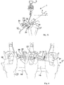
- Figure 1 shows a part of a slaughter line 1 which is provided with a guide rail 2 extending along a transport path.
- the slaughter line 1 further comprises product carriers 3 provided at regular intervals, which product carriers are interconnected via a conveyor chain 4.
- Each product carrier 3 is provided with a guide part 4 on the upper side and with a hook part 5 thereunder.
- the guide parts 4 are provided with running wheels 6, on which the product carriers 3 can roll in the direction of movement 24 along the guide rail 2 when the conveyor chain 4 is being driven.
- the pitch between adjacent product carriers 3 is 8 inches, or in other words, about 200 mm. Also other dimensions, such as 6 inches (152 mm), 8 inches) 203 mm), 10 inches (254 mm) or 12 inches (305 mm) are quite conceivable.
- the hook part 5 has an at least substantially hooked J-shape (see also figure 3 ) and has a widened slot part 7 at the bottom end, in which two identically shaped slots 8 (see also figures 2a-2d ) are provided.
- the slots 8 each have a length I.
- the slot part 7 has a direction of inclination 9 ( figure 3 ) that includes an angle ⁇ of 45° with a horizontal line 10 that extends perpendicular to the direction of movement 24.
- the slots 8 each have a laterally facing open upper end 11 and a closed lower end 12.
- the slots 8 taper off slightly from the upper end 11 to the lower end 12 and have a constant width over a certain part of the length of the slots 8 at the lower end 12. Said width is adapted to the dimensions of bird legs, so that said legs can be accommodated in the lower end 12 with a slight clamping fit, such that the tarsal joint will remain above the lower end 12 of the slots.
- the slaughter line 1 further comprises a removing device 15, which is rigidly suspended from the guide rail 2 via a support construction 16.
- the removing device 15 comprises a table body 17, which is rigidly connected, via an upright part 18, to the vertical part of the support construction 16, and which further comprises a tabletop 19.
- the tabletop 19 extends parallel to the direction of inclination 9 of the slot parts 7 that form part of hook parts 5 of passing product carriers 3.
- the removing device 15 comprises a first, upstream pusher arm 21 and a second, downstream pusher arm 22.
- the first pusher arm 21 is connected to the tabletop 19 such that it can pivot to and fro, between a passive position and an active position, about a pivot axis 23 that extends perpendicular to the tabletop 19.
- the first pusher arm 21 In the passive position of the first pusher arm 21, as shown in figures 2a and 2d , the first pusher arm 21 extends outside the path of birds 13 suspended from passing product carriers 3, more or less parallel to the conveying direction 24, on the downstream side of the pivot axis 23.
- the first pusher arm 21, or at least part thereof is located in the path of passing birds 13, more specifically in the path of the legs 14 thereof.
- the first pusher arm 21 In the active position, the first pusher arm 21 extends at an angle of about 23 degrees relative to the conveying direction 24, seen in a direction perpendicular to a plane parallel to the table 19, or in other words, parallel to the slot part 7. In the active position, the end of the first pusher arm 21 is located approximately halfway the length of the slots 8, seen in top plan view. Exactly at that location, the slots 8 widen in the direction of the upper open ends 11.
- the second pusher arm 22 is likewise connected to the tabletop 19 such that it can pivot to and fro between a passive position and an active position about a pivot axis 25, which likewise extends perpendicular to the tabletop 19.
- the passive position of the second pusher arm 22 as shown in figures 2a and 2d , the second pusher arm 22 extends outside the path of birds 13 suspended from passing product carriers 3, more or less parallel to the conveying direction 24, on the downstream side of the pivot axis 25.
- the second pusher arm 22, or at least part thereof is located in the path of passing birds 13, more specifically in the path of the legs 14 thereof.
- the second pusher arm 22 extends at an angle of about 33 degrees relative to the conveying direction 24, seen in a direction perpendicular to a plane parallel to the table 19, or in other words, parallel to the slot part 7.
- the end of the second pusher arm 22 is located near the upper ends 11 of the slots 8, seen in top plan view, upon passage of the associated product carriers 3.
- the pusher arms 21 and 22 are located under the tabletop 19 and are connected to an end of a connecting arm 33, 34 via respective shaft members 31, 32 which extend through the tabletop 19, being pivotally journalled therein.
- the central axes of the shaft members 31, 32 coincide with the respective pivot axes 23, 25.
- the connecting arms 33, 34 are connected to the ends of piston rods 35, 36 associated with pneumatic cylinders 37, 38 which are connected to the tabletop 19 such that they can pivot to and fro about pivot axes 39, 40.
- Suitable actuation of the cylinders 37, 38 which can be individually controlled by means of a control unit (not shown), causes the associated pusher elements 21, 22 to pivot between the associated active and passive positions.
- the first pusher arm 21 is to a limited extent located closer to the tabletop 19 than the second pusher arm 22, so that there may be some overlap between the two pusher arms 21 and 22, as is shown in figure 2a and in particular in figure 2d .
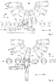
- the starting situation is the situation shown in figure 2a .
- the control system of the slaughter line 1 delivers a command to the control unit of the removing device 15 that an approaching bird 13' is to be removed from the associated product carrier 3.
- the first pusher arm 21 is made to pivot from the passive position to the active position thereof ( figure 2b ) by suitable actuation of the cylinder 37 as soon as the adjacent downstream bird 13 offers space for such pivoting of the first pusher arm 21.
- the result of the pivoting of the first pusher arm 21 is that the first pusher arm 21 comes to lie in the path of the legs 14 of the bird 13', and because of the previously described inclined orientation of the first pusher arm 21 relative to the conveying direction 24, the legs 14 of the bird 13' are pushed sideways one after the other from the closed lower ends 12 of the associated slots 8 in the direction of the upper ends 11. The legs remain suspended in the slots 8, however.
- the second pusher arm 22 will be pivoted from the passive position to the active position thereof as soon as the downstream bird 13 offers space for this, which is before the bird 13' has fully passed the first pusher arm 21.
- the second pusher arm 22 is so positioned relative to the first pusher arm 21 that in the respective active positions thereof the end of the first pusher arm 21 joins the second pusher arm 22, as shown in figure 2c .
- the second pusher arm 22 will also come to lie in the path of the legs 14 and take over the guiding function for the legs of the bird 13' from the first pusher arm and push the legs 14 further in the direction of the open ends 11 of the slots 8 until the legs 14 come clear of the slots 8.
- the legs 14 are more quickly guided in lateral direction by the second pusher arm 22 than by the first pusher arm 21. This reduces the cycle time.
- the inclination of the first pusher arm 21 in the active position is limited on account of mass inertia effects and the possible need to overcome also friction forces that act between the legs 14 and the tapered slots 8. If the legs 14 are guided in lateral direction too quickly by the first pusher arm 21, the risk of damage to the legs 14 will be greater.
- the vertical axis shows the lateral movement (i.e. in horizontal direction perpendicular to the direction of movement 24) of (the ends of) the first and the second pusher arm 21, 22 and also of the legs 14 of a bird 13'.
- y indicated on the vertical axis
- y - I x cos( ⁇ ) applies.
- the interval between the forward movement of the first pusher arm 21 and the return movement of the second pusher arm 22 could be 275 ms.
- the first pusher arm 21 will pivot back again from the active position to the passive position as shown in figure 2d .
- the pusher arms 21, 22 need not pivot back to their respective passive positions. Said pivoting back will only happen in a situation in which a bird 13 in an adjacent upstream product carrier 3 need not be removed from said product carrier 3.
- the removing device 15 can fall into a collecting bin, for example, under the influence of the force of gravity.
- the removing device 15 can use a so-called transfer device as shown in figure 5 .
- the product carrier 40 forms part of an transfer station 45 as described in detail in European publication EP 1 848 282 B1 .
- the product carrier 40 has two slots 41, which are spaced the same distance apart as the slots 8 of a product carrier 3.
- the product carrier 40 forms part of a carousel, to which product carrier a parallel, synchronised movement with the product carrier 3 is imparted at the location of the removing device 15, during which movement slots 41 of the product carrier 40 and slots 8 of the product carrier 3 are temporarily aligned.
- a bird is pushed from the product carrier 3 into the product carrier 40 in a manner already explained in the foregoing. It is conceivable in that regard for the hook parts 5 to be slightly tilted about a tilt axis that extends parallel to the conveying direction 24, so that the associated slot parts will have a flatter orientation, making it easier to remove birds 13 from the product carriers 3.
- Figure 6 relates to a second embodiment of the present invention.
- elements of the second embodiment correspond to elements of the first embodiment shown in figures 1-5 , corresponding reference numerals will be used.
- FIGS 6-8 show a slaughter line 101, or at least a part thereof that is relevant to the invention.
- the slaughter line 101 comprises a removing device 115.
- the removing device 115 comprises a pusher arm 121 which can be made to pivot to and fro between a passive position ( figure 6 , figure 7a in dotted line) and an active position ( figures 7a-7c ) about a pivot axis 123 by suitable actuation of the cylinder 137.
- the removing device 115 further comprises a pusher arm 122 which will be indicated hereinafter by the term "ejector arm” 122.
- the ejector arm 122 can be made to pivot to and fro between a passive position ( figures 6 , 7a, 7b ) and an active position ( figure 7c ) about a pivot axis 125 that extends parallel to the conveying direction 24 by suitable actuation of the cylinder 138.
- An alternative embodiment of a pusher arm as the pusher arm 122 is described in EP 819 382 B1 , in particular with reference to figure 18 thereof.
- the starting situation is the situation shown in figure 6 or figure 7a insofar as the pusher arm 121 is in the passive position illustrated in the dotted line. In said starting position, also the ejector arm 122 is in the passive position.
- the control system of the slaughter line 101 delivers the command to the control unit of the removing device 115 that a bird 113' must be removed from the associated product carrier 3.
- the pusher arm 121 will move from the passive position to the active position.
- the upstream leg 114 of the bird 113' will be pushed from the lower end 12 of the slot 8 in question to approximately halfway the length of said slot 8 by and during the movement of the pusher arm 121 to the passive position.
- the downstream leg 114 of the bird 113' will strike the pusher arm 121 and be pushed aside in the directly opposite the ejector arm 122 ( figure 7b ) as a result of the movement of the slaughter line, the ejector arm 122 will be briefly moved from the passive position to the active position and back to the passive position again.
- the ejector arm 122 pushes, more specifically bumps, the legs 114 of the bird 113' toward the open end 11 out of the slots 8 ( figures 7c ).
- the pusher arm 121 will then pivot back to the passive position.
- the vertical axis indicates the lateral movement (i.e. in horizontal direction perpendicular to the direction of movement 24) of the end of the pusher arm 121 and of the ejector arm 122 and also of the legs 14 of a bird 13'.
- the legs 14 move jointly with the ejector arm 122 during the stroke from the active position to the passive position.
- the return movement of the pusher arm 121 to the passive position takes place between the forward movement of the ejector arm 122 and the return movement of the ejector arm 122 in the diagram, said movement could also take place shortly before the forward movement of the ejector arm 122 or after, for example shortly after, the return movement of the ejector arm 122.
- the interval between the forward movement of the first pusher arm 121 and the return movement of the ejector arm 122 could be 200 ms.
- Figure 8 shows how the removing device 115 can also be used for transferring birds in a transfer station comparable to the one shown in figure 5 .
Landscapes
- Life Sciences & Earth Sciences (AREA)
- Engineering & Computer Science (AREA)
- Wood Science & Technology (AREA)
- Zoology (AREA)
- Food Science & Technology (AREA)
- Processing Of Meat And Fish (AREA)
- Framework For Endless Conveyors (AREA)
Claims (15)
- Kombination einer Fördervorrichtung für den Transport von Schlachttieren, die an Produktträgern (3) der Fördervorrichtung aufgehängt sind, wobei die Schlachttiere während des Transports einen Pfad beschreiben, und einer Abtrennvorrichtung (15), die entlang des Pfades angeordnet ist, um ausgewählte Schlachttiere von den Produktträgern abzutrennen, wobei die Fördervorrichtung eine entlang eines Transportpfades verlaufende Führung (2) aufweist, sowie Produktträger (3) für die Schlachttiere, die entlang der Führung in einer Bewegungsrichtung bewegbar sind, wobei jeder Produktträger mindestens eine Nut (8) aufweist, die einer Neigungsrichtung entsprechend geneigt ist, um mindestens einen gehaltenen Teil eines Schlachttiers darin zu halten, wobei die mindestens eine Nut ein offenes oberes Ende (11) und ein unteres Ende (12) hat und relativ zu der Fördervorrichtung, zumindest am Ort der Abtrennvorrichtung, seitlich ausgerichtet ist, wobei die Abtrennvorrichtung ein Abschiebeelement (21) aufweist, und Bewegungsmittel, um das Abschiebeelement zwischen einer inaktiven Stellung, in welcher das Abschiebeelement außerhalb des Pfades der Schlachttiere angeordnet ist, und einer aktiven Stellung, in welcher das Abschiebeelement im Pfad des mindestens einen gehaltenen Teils eines ausgewählten Schlachttiers in der aktiven Stellung angeordnet ist, hin und her oder zumindest während der Bewegung aus der inaktiven Stellung in die aktive Stellung zu bewegen, um den mindestens einen gehaltenen Teil des ausgewählten Schlachttiers aus der mindestens einen Nut eines Produktträgers über das obere offene Ende der mindestens einen Nut zu schieben, dadurch gekennzeichnet, dass die Abtrennvorrichtung ein weiteres Abschiebeelement (22) aufweist, sowie weitere Bewegungsmittel, um das weitere Abschiebeelement zwischen einer weiteren inaktiven Stellung, in welcher das weitere Abschiebeelement außerhalb des Pfades der Schlachttiere angeordnet ist, und einer weiteren aktiven Stellung, in welcher das weitere Abschiebeelement im Pfad des mindestens einen gehaltenen Teils des ausgewählten Schlachttiers angeordnet ist, hin und her oder zumindest während seiner Bewegung aus der weiteren inaktiven Stellung in die weitere aktive Stellung zu bewegen, um den mindestens einen gehaltenen Teil des ausgewählten Schlachttiers aus dem unteren Ende in Richtung des oberen Endes zu einer Zwischenposition zu schieben, wobei das Abschiebeelement so konstruiert ist, dass es den mindestens einen gehaltenen Teil eines Schlachttiers aus der Zwischenposition über das obere Ende der mindestens einen Nut eines Produktträgers aus der mindestens einen Nut in der aktiven Stellung oder während seiner Bewegung aus der inaktiven Stellung in die aktive Stellung schiebt.
- Kombination nach Anspruch 1, dadurch gekennzeichnet, dass das Abschiebeelement zwischen der inaktiven Stellung und der aktiven Stellung um eine Schwenkachse schwenkbar ist.
- Kombination nach Anspruch 2, dadurch gekennzeichnet, dass sich die Schwenkachse senkrecht zu der Bewegungsrichtung erstreckt.
- Kombination nach Anspruch 3, dadurch gekennzeichnet, dass die Schwenkachse auf einer stromaufwärts gelegenen Seite des Abschiebeelements vorgesehen ist.
- Kombination nach einem der vorhergehenden Ansprüche, dadurch gekennzeichnet, dass das weitere Abschiebeelement um eine weitere Schwenkachse zwischen der weiteren inaktiven Stellung und der weiteren aktiven Stellung schwenkbar ist.
- Kombination nach einem der vorhergehenden Ansprüche, dadurch gekennzeichnet, dass das weitere Abschiebeelement in seiner weiteren inaktiven Stellung zumindest teilweise stromaufwärts des Abschiebeelements in dessen inaktiver Stellung angeordnet ist.
- Kombination nach einem der vorhergehenden Ansprüche, dadurch gekennzeichnet, dass das Abschiebeelement zumindest in seiner aktiven Stellung und/oder das weitere Abschiebeelement in dessen weiterer aktiver Stellung so konstruiert ist/sind, dass der mindestens eine gehaltene Teil eines ausgewählten Schlachttiers in der Richtung des offenen Endes der mindestens einen Nut eines Produktträgers während des Transports des Schlachttiers in der Bewegungsrichtung seitlich geführt wird, zu welchem Zweck das Abschiebeelement und/oder das weitere Abschiebeelement jeweils eine Führungsfläche und/oder eine weitere Führungsfläche aufweisen, wobei in Draufsicht gesehen die Führungsfläche und/oder die weitere Führungsfläche einen spitzen Winkel zur Transportrichtung in der aktiven Stellung und/oder der weiteren aktiven Stellung einschließt bzw. einschließen.
- Kombination nach Anspruch 7, dadurch gekennzeichnet, dass das Abschiebeelement in seiner aktiven Stellung und das weitere Abschiebeelement in dessen weiterer aktiver Stellung so konstruiert sind, dass sie den mindestens einen gehaltenen Teil eines ausgewählten Schlachttiers seitlich führen, wobei der Winkel, welchen die Führungsfläche mit der Transportrichtung einschließt, größer ist als der Winkel, welchen die weitere Führungsfläche mit der Transportrichtung einschließt.
- Kombination nach einem der vorhergehenden Ansprüche, dadurch gekennzeichnet, dass die Kombination weitere Produktträger aufweist, die entlang einem weiteren Transportpfad bewegbar sind, welche weiteren Produktträger so konstruiert sind, dass sie die Schlachttiere übernehmen, deren mindestens einer gehaltene Teil aus der mindestens einen Nut durch das Abschiebeelement über das obere Ende der mindestens einen Nut eines Produktträgers herausgeschoben wurde.
- Kombination nach einem der vorhergehenden Ansprüche, dadurch gekennzeichnet, dass die Bewegungsmittel und die weiteren Bewegungsmittel so konstruiert sind, dass sie die folgenden Schritte ausführen, um den mindestens einen gehaltenen Teil eines Schlachttiers aus der mindestens einen Nut herauszuschieben:A Bewegen des weiteren Abschiebeelements aus der weiteren inaktiven Stellung in die weitere aktive Stellung, um den mindestens einen gehaltenen Teil eines Schlachttiers von dem unteren Ende der mindestens einen Nut in Richtung des oberen Endes der mindestens einen Nut in eine Zwischenposition während Schritt A oder infolge Schritt A zu schieben,B Bewegen des Abschiebeelements aus der inaktiven Stellung in die aktive Stellung nach Schritt A, um den mindestens einen gehaltenen Teil des Schlachttiers aus der Zwischenposition über das obere Ende der mindestens einen Nut eines Produktträgers aus der mindestens einen Nut während Schritt B oder infolge Schritt B zu schieben,C Bewegen des weiteren Abschiebeelements aus der weiteren aktiven Stellung zurück in die weitere inaktive Stellung nach Schritt B,D Bewegen des Abschiebeelements aus der aktiven Stellung zurück in die inaktive Stellung nach Schritt B.
- Verfahren für den Betrieb einer Kombination einer Fördervorrichtung und einer Abtrennvorrichtung (15) gemäß einem der vorhergehenden Ansprüche, umfassend die Schritte:A Bewegen des weiteren Abschiebeelements (22) aus der weiteren inaktiven Stellung in die weitere aktive Stellung, um den mindestens einen gehaltenen Teil eines Schlachttiers von dem unteren Ende der mindestens einen Nut in Richtung des oberen Endes der mindestens einen Nut in eine Zwischenposition während Schritt A oder infolge Schritt A zu schieben,B Bewegen des Abschiebeelements (21) aus der inaktiven Stellung in die aktive Stellung nach Schritt A, um den mindestens einen gehaltenen Teil des Schlachttiers aus der Zwischenposition über das obere Ende der mindestens einen Nut eines Produktträgers aus der mindestens einen Nut während Schritt B oder infolge Schritt B zu schieben,C Bewegen des weiteren Abschiebeelements aus der weiteren aktiven Stellung zurück in die weitere inaktive Stellung nach Schritt B,D Bewegen des Abschiebeelements aus der aktiven Stellung zurück in die inaktive Stellung nach Schritt B.
- Verfahren nach Anspruch 11, wobei Schritt D nach Schritt C ausgeführt wird.
- Verfahren nach Anspruch 11, wobei Schritt B gleichzeitig mit oder vor Schritt C ausgeführt wird.
- Verfahren nach einem der Ansprüche 11 bis 13, das während des Betriebs einer Kombination nach Anspruch 9 ausgeführt wird, dadurch gekennzeichnet, dass ein Schlachttier von einem Produktträger durch einen weiteren Produktträger während Schritt B oder zwischen den Schritten B und D übernommen wird.
- Abtrennvorrichtung zur Verwendung in einer Kombination nach einem der Ansprüche 1 bis 10, umfassend ein Abschiebeelement (21), Bewegungsmittel, um das Abschiebeelement zwischen einer inaktiven Stellung, in welcher das Abschiebeelement außerhalb des Pfades der Schlachttiere angeordnet ist, und einer aktiven Stellung, in welcher das Abschiebeelement im Pfad des mindestens einen gehaltenen Teils eines ausgewählten Schlachttiers in der aktiven Stellung angeordnet ist, hin und her oder zumindest während der Bewegung aus der inaktiven Stellung in die aktive Stellung zu bewegen, um den mindestens einen gehaltenen Teil des ausgewählten Schlachttiers aus der mindestens einen Nut eines Produktträgers über das obere offene Ende der mindestens einen Nut zu schieben, dadurch gekennzeichnet, dass die Abtrennvorrichtung ein weiteres Abschiebeelement (22) aufweist sowie weitere Bewegungsmittel, um das weitere Abschiebeelement zwischen einer weiteren inaktiven Stellung, in welcher das weitere Abschiebeelement außerhalb des Pfades der Schlachttiere angeordnet ist, und einer weiteren aktiven Stellung, in welcher das weitere Abschiebeelement im Pfad des mindestens einen gehaltenen Teils des ausgewählten Schlachttiers angeordnet ist, hin und her oder zumindest während seiner Bewegung aus der weiteren inaktiven Stellung in die weitere aktive Stellung zu bewegen, um den mindestens einen gehaltenen Teil des ausgewählten Schlachttiers aus dem unteren Ende in Richtung des oberen Endes zu einer Zwischenposition zu schieben, wobei das Abschiebeelement so konstruiert ist, dass es den mindestens einen gehaltenen Teil eines Schlachttiers von der Zwischenposition über das obere Ende der mindestens einen Nut eines Produktträgers aus der mindestens einen Nut in der aktiven Stellung oder während seiner Bewegung aus der inaktiven Stellung in die aktive Stellung schiebt.
Applications Claiming Priority (2)
| Application Number | Priority Date | Filing Date | Title |
|---|---|---|---|
| NL2011946A NL2011946C2 (nl) | 2013-12-12 | 2013-12-12 | Combinatie van een transportinrichting voor slachtdieren en een losinrichting alsmede werkwijze voor het bedrijven van een dergelijke combinatie. |
| PCT/NL2014/050851 WO2015088340A1 (en) | 2013-12-12 | 2014-12-11 | A combination of a conveying device for slaughter animals and removing device, as well as a method for operating such combination |
Publications (2)
| Publication Number | Publication Date |
|---|---|
| EP3079477A1 EP3079477A1 (de) | 2016-10-19 |
| EP3079477B1 true EP3079477B1 (de) | 2017-09-27 |
Family
ID=50190662
Family Applications (1)
| Application Number | Title | Priority Date | Filing Date |
|---|---|---|---|
| EP14828324.5A Active EP3079477B1 (de) | 2013-12-12 | 2014-12-11 | Kombination einer fördervorrichtung für schlachttiere und einer beseitigungsvorrichtung sowie verfahren zum betrieb solch einer kombination |
Country Status (9)
| Country | Link |
|---|---|
| US (1) | US9615592B2 (de) |
| EP (1) | EP3079477B1 (de) |
| JP (1) | JP6297697B2 (de) |
| KR (1) | KR102342927B1 (de) |
| CN (1) | CN206137038U (de) |
| BR (1) | BR112016013453B1 (de) |
| DK (1) | DK3079477T3 (de) |
| NL (1) | NL2011946C2 (de) |
| WO (1) | WO2015088340A1 (de) |
Families Citing this family (6)
| Publication number | Priority date | Publication date | Assignee | Title |
|---|---|---|---|---|
| CN112654250B (zh) * | 2018-09-03 | 2022-07-05 | Fpi食品加工创新有限两合公司 | 用于传送家禽的机组和方法 |
| JP7473387B2 (ja) * | 2020-05-12 | 2024-04-23 | 株式会社前川製作所 | ワーク移送装置 |
| JP7473388B2 (ja) * | 2020-05-12 | 2024-04-23 | 株式会社前川製作所 | ワーク移載装置 |
| WO2022174879A1 (en) * | 2021-02-22 | 2022-08-25 | John M. Christensen Holding Aps | A method and an apparatus for removing a broiler from an overhead sorting conveyor |
| KR102529307B1 (ko) | 2021-03-30 | 2023-05-08 | 엄성희 | 도축한 육류 이송용 체인장치 |
| CN117945064B (zh) * | 2024-03-27 | 2024-06-14 | 四川远方云天食品科技有限公司 | 一种火锅底料成品的输送设备 |
Family Cites Families (12)
| Publication number | Priority date | Publication date | Assignee | Title |
|---|---|---|---|---|
| NL8902847A (nl) * | 1989-11-17 | 1991-06-17 | Terpa Poultry Bv | Kippen overname. |
| US5453045A (en) * | 1993-01-21 | 1995-09-26 | Systemate Holland, B.V. | System for transferring birds from one conveyor system to another with intermediate accumulator |
| NL1000935C2 (nl) * | 1995-08-04 | 1997-02-06 | Stork Pmt | Inrichting en werkwijze voor het bewerken van een slachtdier. |
| EP0858740B1 (de) * | 1997-02-12 | 2001-11-07 | Nordischer Maschinenbau Rud. Baader Gmbh + Co Kg | Einrichtung zum Bearbeiten der Beine von Geflügel |
| NL1006286C2 (nl) * | 1997-06-11 | 1998-12-14 | Tieleman Food Equipment B V | Hangtransportsysteem voor geslachte kippen of ander pluimvee. |
| US6033299A (en) * | 1998-09-11 | 2000-03-07 | Tyson Foods, Inc. | Carcass transfer apparatus |
| NL1012703C2 (nl) | 1999-04-06 | 2000-10-09 | Stork Pmt | Werkwijze en inrichting voor het bewerken van een gevogeltepoot. |
| NL1014845C1 (nl) | 1999-06-11 | 2000-12-12 | Stork Pmt | Inrichting voor het verwerken van een slachtproduct. |
| GB0016516D0 (en) * | 2000-07-06 | 2000-08-23 | Owen Mumford Ltd | Improvements relating to needle protection devices |
| ES2391567T3 (es) * | 2006-11-14 | 2012-11-27 | Linco Food Systems A/S | Aparato para hacer caer aves de corral de ganchos |
| JP5351537B2 (ja) * | 2009-02-04 | 2013-11-27 | マルイ食品株式会社 | 家禽の処理加工方法 |
| DK2622963T3 (en) * | 2012-02-03 | 2018-04-30 | Nordischer Maschinenbau | Arrangement for lateral scratching on both sides of the skin of a slaughtered animal body in saddle position, support body saddling the animal body, in such an arrangement, processing machine which .... |
-
2013
- 2013-12-12 NL NL2011946A patent/NL2011946C2/nl not_active IP Right Cessation
-
2014
- 2014-12-11 JP JP2016538583A patent/JP6297697B2/ja active Active
- 2014-12-11 US US15/102,815 patent/US9615592B2/en active Active
- 2014-12-11 BR BR112016013453-2A patent/BR112016013453B1/pt active IP Right Grant
- 2014-12-11 EP EP14828324.5A patent/EP3079477B1/de active Active
- 2014-12-11 CN CN201490001323.6U patent/CN206137038U/zh not_active Expired - Lifetime
- 2014-12-11 KR KR1020167018674A patent/KR102342927B1/ko active Active
- 2014-12-11 DK DK14828324.5T patent/DK3079477T3/en active
- 2014-12-11 WO PCT/NL2014/050851 patent/WO2015088340A1/en not_active Ceased
Non-Patent Citations (1)
| Title |
|---|
| None * |
Also Published As
| Publication number | Publication date |
|---|---|
| EP3079477A1 (de) | 2016-10-19 |
| KR20160096703A (ko) | 2016-08-16 |
| DK3079477T3 (en) | 2017-12-04 |
| WO2015088340A8 (en) | 2015-07-23 |
| US9615592B2 (en) | 2017-04-11 |
| JP2016539649A (ja) | 2016-12-22 |
| WO2015088340A1 (en) | 2015-06-18 |
| JP6297697B2 (ja) | 2018-03-20 |
| BR112016013453B1 (pt) | 2021-02-09 |
| US20170020145A1 (en) | 2017-01-26 |
| CN206137038U (zh) | 2017-05-03 |
| KR102342927B1 (ko) | 2021-12-24 |
| NL2011946C2 (nl) | 2015-06-15 |
Similar Documents
| Publication | Publication Date | Title |
|---|---|---|
| US9615592B2 (en) | Combination of a conveying device for slaughter animals and removing device, as well as a method for operating such combination | |
| US8105138B2 (en) | Device and method for conditioning slaughtered poultry and production line for processing poultry carcasses | |
| US8695781B2 (en) | Machine for forming groups of products for the casing thereof | |
| US9795149B2 (en) | Positioning device for positioning poultry legs conveyed in single file in the conveying direction along a conveyor section and the method comprising said positioning for removing the thigh meat from poultry legs | |
| US3643293A (en) | Poultry transfer apparatus and method | |
| EP3247643B1 (de) | Übertragungsvorrichtung für eier | |
| US20140166435A1 (en) | Apparatus and Method of Egg Transfer Within an Egg Handling Machine | |
| US20120325622A1 (en) | Machine and method for forming groups of products to be cased | |
| JP7519370B2 (ja) | 家禽移送装置 | |
| JPS5864914A (ja) | 推積状物品を整合させる装置 | |
| US10099865B2 (en) | Method and device for conveying piece products | |
| JP7524217B2 (ja) | オーバーハングレール搬送システム | |
| JP2013527824A (ja) | 卵供給装置および方法、例えばトレイ充填装置および方法 | |
| EP1460007A1 (de) | Einrichtung zum Fördern von Stückgütern, insbesondere für eine automatische Verpackungsmachine, und Verfahren zu ihrer Verwendung | |
| US4212584A (en) | Material handling apparatus | |
| EP2377763B1 (de) | Vorrichtung und Verfahren zum Wenden von Eiern | |
| NL1027804C2 (en) | Plant pot sorting method, used in greenhouses, comprises arranging pots into row and holding pots with retaining mechanism while moving front pot away from row | |
| US7435167B2 (en) | Apparatus and method for transferring leg quarter from shackle | |
| WO2022174879A1 (en) | A method and an apparatus for removing a broiler from an overhead sorting conveyor | |
| NL8902847A (nl) | Kippen overname. | |
| NL9000112A (nl) | Transportinrichting voor slachtdieren. | |
| WO2007086740A1 (en) | Apparatus for filling trays or similar packaging units | |
| WO2013137724A1 (en) | Product handover arrangement |
Legal Events
| Date | Code | Title | Description |
|---|---|---|---|
| PUAI | Public reference made under article 153(3) epc to a published international application that has entered the european phase |
Free format text: ORIGINAL CODE: 0009012 |
|
| 17P | Request for examination filed |
Effective date: 20160616 |
|
| AK | Designated contracting states |
Kind code of ref document: A1 Designated state(s): AL AT BE BG CH CY CZ DE DK EE ES FI FR GB GR HR HU IE IS IT LI LT LU LV MC MK MT NL NO PL PT RO RS SE SI SK SM TR |
|
| AX | Request for extension of the european patent |
Extension state: BA ME |
|
| DAX | Request for extension of the european patent (deleted) | ||
| GRAP | Despatch of communication of intention to grant a patent |
Free format text: ORIGINAL CODE: EPIDOSNIGR1 |
|
| INTG | Intention to grant announced |
Effective date: 20170419 |
|
| GRAS | Grant fee paid |
Free format text: ORIGINAL CODE: EPIDOSNIGR3 |
|
| GRAA | (expected) grant |
Free format text: ORIGINAL CODE: 0009210 |
|
| AK | Designated contracting states |
Kind code of ref document: B1 Designated state(s): AL AT BE BG CH CY CZ DE DK EE ES FI FR GB GR HR HU IE IS IT LI LT LU LV MC MK MT NL NO PL PT RO RS SE SI SK SM TR |
|
| REG | Reference to a national code |
Ref country code: GB Ref legal event code: FG4D |
|
| REG | Reference to a national code |
Ref country code: CH Ref legal event code: EP |
|
| REG | Reference to a national code |
Ref country code: AT Ref legal event code: REF Ref document number: 931144 Country of ref document: AT Kind code of ref document: T Effective date: 20171015 |
|
| REG | Reference to a national code |
Ref country code: IE Ref legal event code: FG4D |
|
| REG | Reference to a national code |
Ref country code: NL Ref legal event code: FP |
|
| REG | Reference to a national code |
Ref country code: DE Ref legal event code: R096 Ref document number: 602014015216 Country of ref document: DE |
|
| REG | Reference to a national code |
Ref country code: DK Ref legal event code: T3 Effective date: 20171128 |
|
| REG | Reference to a national code |
Ref country code: FR Ref legal event code: PLFP Year of fee payment: 4 |
|
| PG25 | Lapsed in a contracting state [announced via postgrant information from national office to epo] |
Ref country code: FI Free format text: LAPSE BECAUSE OF FAILURE TO SUBMIT A TRANSLATION OF THE DESCRIPTION OR TO PAY THE FEE WITHIN THE PRESCRIBED TIME-LIMIT Effective date: 20170927 Ref country code: LT Free format text: LAPSE BECAUSE OF FAILURE TO SUBMIT A TRANSLATION OF THE DESCRIPTION OR TO PAY THE FEE WITHIN THE PRESCRIBED TIME-LIMIT Effective date: 20170927 Ref country code: NO Free format text: LAPSE BECAUSE OF FAILURE TO SUBMIT A TRANSLATION OF THE DESCRIPTION OR TO PAY THE FEE WITHIN THE PRESCRIBED TIME-LIMIT Effective date: 20171227 Ref country code: SE Free format text: LAPSE BECAUSE OF FAILURE TO SUBMIT A TRANSLATION OF THE DESCRIPTION OR TO PAY THE FEE WITHIN THE PRESCRIBED TIME-LIMIT Effective date: 20170927 Ref country code: HR Free format text: LAPSE BECAUSE OF FAILURE TO SUBMIT A TRANSLATION OF THE DESCRIPTION OR TO PAY THE FEE WITHIN THE PRESCRIBED TIME-LIMIT Effective date: 20170927 |
|
| REG | Reference to a national code |
Ref country code: LT Ref legal event code: MG4D |
|
| REG | Reference to a national code |
Ref country code: AT Ref legal event code: MK05 Ref document number: 931144 Country of ref document: AT Kind code of ref document: T Effective date: 20170927 |
|
| PG25 | Lapsed in a contracting state [announced via postgrant information from national office to epo] |
Ref country code: RS Free format text: LAPSE BECAUSE OF FAILURE TO SUBMIT A TRANSLATION OF THE DESCRIPTION OR TO PAY THE FEE WITHIN THE PRESCRIBED TIME-LIMIT Effective date: 20170927 Ref country code: BG Free format text: LAPSE BECAUSE OF FAILURE TO SUBMIT A TRANSLATION OF THE DESCRIPTION OR TO PAY THE FEE WITHIN THE PRESCRIBED TIME-LIMIT Effective date: 20171227 Ref country code: GR Free format text: LAPSE BECAUSE OF FAILURE TO SUBMIT A TRANSLATION OF THE DESCRIPTION OR TO PAY THE FEE WITHIN THE PRESCRIBED TIME-LIMIT Effective date: 20171228 Ref country code: LV Free format text: LAPSE BECAUSE OF FAILURE TO SUBMIT A TRANSLATION OF THE DESCRIPTION OR TO PAY THE FEE WITHIN THE PRESCRIBED TIME-LIMIT Effective date: 20170927 |
|
| PG25 | Lapsed in a contracting state [announced via postgrant information from national office to epo] |
Ref country code: CZ Free format text: LAPSE BECAUSE OF FAILURE TO SUBMIT A TRANSLATION OF THE DESCRIPTION OR TO PAY THE FEE WITHIN THE PRESCRIBED TIME-LIMIT Effective date: 20170927 Ref country code: ES Free format text: LAPSE BECAUSE OF FAILURE TO SUBMIT A TRANSLATION OF THE DESCRIPTION OR TO PAY THE FEE WITHIN THE PRESCRIBED TIME-LIMIT Effective date: 20170927 |
|
| PG25 | Lapsed in a contracting state [announced via postgrant information from national office to epo] |
Ref country code: SM Free format text: LAPSE BECAUSE OF FAILURE TO SUBMIT A TRANSLATION OF THE DESCRIPTION OR TO PAY THE FEE WITHIN THE PRESCRIBED TIME-LIMIT Effective date: 20170927 Ref country code: AT Free format text: LAPSE BECAUSE OF FAILURE TO SUBMIT A TRANSLATION OF THE DESCRIPTION OR TO PAY THE FEE WITHIN THE PRESCRIBED TIME-LIMIT Effective date: 20170927 Ref country code: IS Free format text: LAPSE BECAUSE OF FAILURE TO SUBMIT A TRANSLATION OF THE DESCRIPTION OR TO PAY THE FEE WITHIN THE PRESCRIBED TIME-LIMIT Effective date: 20180127 Ref country code: EE Free format text: LAPSE BECAUSE OF FAILURE TO SUBMIT A TRANSLATION OF THE DESCRIPTION OR TO PAY THE FEE WITHIN THE PRESCRIBED TIME-LIMIT Effective date: 20170927 Ref country code: SK Free format text: LAPSE BECAUSE OF FAILURE TO SUBMIT A TRANSLATION OF THE DESCRIPTION OR TO PAY THE FEE WITHIN THE PRESCRIBED TIME-LIMIT Effective date: 20170927 |
|
| REG | Reference to a national code |
Ref country code: DE Ref legal event code: R097 Ref document number: 602014015216 Country of ref document: DE |
|
| REG | Reference to a national code |
Ref country code: CH Ref legal event code: PL |
|
| PLBE | No opposition filed within time limit |
Free format text: ORIGINAL CODE: 0009261 |
|
| STAA | Information on the status of an ep patent application or granted ep patent |
Free format text: STATUS: NO OPPOSITION FILED WITHIN TIME LIMIT |
|
| PG25 | Lapsed in a contracting state [announced via postgrant information from national office to epo] |
Ref country code: PL Free format text: LAPSE BECAUSE OF FAILURE TO SUBMIT A TRANSLATION OF THE DESCRIPTION OR TO PAY THE FEE WITHIN THE PRESCRIBED TIME-LIMIT Effective date: 20170927 |
|
| 26N | No opposition filed |
Effective date: 20180628 |
|
| REG | Reference to a national code |
Ref country code: IE Ref legal event code: MM4A |
|
| PG25 | Lapsed in a contracting state [announced via postgrant information from national office to epo] |
Ref country code: MT Free format text: LAPSE BECAUSE OF NON-PAYMENT OF DUE FEES Effective date: 20171211 Ref country code: LU Free format text: LAPSE BECAUSE OF NON-PAYMENT OF DUE FEES Effective date: 20171211 |
|
| REG | Reference to a national code |
Ref country code: BE Ref legal event code: MM Effective date: 20171231 |
|
| PG25 | Lapsed in a contracting state [announced via postgrant information from national office to epo] |
Ref country code: IE Free format text: LAPSE BECAUSE OF NON-PAYMENT OF DUE FEES Effective date: 20171211 |
|
| PG25 | Lapsed in a contracting state [announced via postgrant information from national office to epo] |
Ref country code: BE Free format text: LAPSE BECAUSE OF NON-PAYMENT OF DUE FEES Effective date: 20171231 Ref country code: SI Free format text: LAPSE BECAUSE OF FAILURE TO SUBMIT A TRANSLATION OF THE DESCRIPTION OR TO PAY THE FEE WITHIN THE PRESCRIBED TIME-LIMIT Effective date: 20170927 Ref country code: CH Free format text: LAPSE BECAUSE OF NON-PAYMENT OF DUE FEES Effective date: 20171231 Ref country code: LI Free format text: LAPSE BECAUSE OF NON-PAYMENT OF DUE FEES Effective date: 20171231 |
|
| PG25 | Lapsed in a contracting state [announced via postgrant information from national office to epo] |
Ref country code: MC Free format text: LAPSE BECAUSE OF FAILURE TO SUBMIT A TRANSLATION OF THE DESCRIPTION OR TO PAY THE FEE WITHIN THE PRESCRIBED TIME-LIMIT Effective date: 20170927 Ref country code: HU Free format text: LAPSE BECAUSE OF FAILURE TO SUBMIT A TRANSLATION OF THE DESCRIPTION OR TO PAY THE FEE WITHIN THE PRESCRIBED TIME-LIMIT; INVALID AB INITIO Effective date: 20141211 |
|
| PG25 | Lapsed in a contracting state [announced via postgrant information from national office to epo] |
Ref country code: RO Free format text: LAPSE BECAUSE OF FAILURE TO SUBMIT A TRANSLATION OF THE DESCRIPTION OR TO PAY THE FEE WITHIN THE PRESCRIBED TIME-LIMIT Effective date: 20170927 |
|
| PG25 | Lapsed in a contracting state [announced via postgrant information from national office to epo] |
Ref country code: CY Free format text: LAPSE BECAUSE OF FAILURE TO SUBMIT A TRANSLATION OF THE DESCRIPTION OR TO PAY THE FEE WITHIN THE PRESCRIBED TIME-LIMIT Effective date: 20170927 |
|
| PG25 | Lapsed in a contracting state [announced via postgrant information from national office to epo] |
Ref country code: MK Free format text: LAPSE BECAUSE OF FAILURE TO SUBMIT A TRANSLATION OF THE DESCRIPTION OR TO PAY THE FEE WITHIN THE PRESCRIBED TIME-LIMIT Effective date: 20170927 |
|
| PG25 | Lapsed in a contracting state [announced via postgrant information from national office to epo] |
Ref country code: TR Free format text: LAPSE BECAUSE OF FAILURE TO SUBMIT A TRANSLATION OF THE DESCRIPTION OR TO PAY THE FEE WITHIN THE PRESCRIBED TIME-LIMIT Effective date: 20170927 |
|
| PG25 | Lapsed in a contracting state [announced via postgrant information from national office to epo] |
Ref country code: PT Free format text: LAPSE BECAUSE OF FAILURE TO SUBMIT A TRANSLATION OF THE DESCRIPTION OR TO PAY THE FEE WITHIN THE PRESCRIBED TIME-LIMIT Effective date: 20170927 |
|
| PG25 | Lapsed in a contracting state [announced via postgrant information from national office to epo] |
Ref country code: AL Free format text: LAPSE BECAUSE OF FAILURE TO SUBMIT A TRANSLATION OF THE DESCRIPTION OR TO PAY THE FEE WITHIN THE PRESCRIBED TIME-LIMIT Effective date: 20170927 |
|
| P01 | Opt-out of the competence of the unified patent court (upc) registered |
Effective date: 20230514 |
|
| PGFP | Annual fee paid to national office [announced via postgrant information from national office to epo] |
Ref country code: NL Payment date: 20251119 Year of fee payment: 12 |
|
| PGFP | Annual fee paid to national office [announced via postgrant information from national office to epo] |
Ref country code: DE Payment date: 20251126 Year of fee payment: 12 |
|
| PGFP | Annual fee paid to national office [announced via postgrant information from national office to epo] |
Ref country code: GB Payment date: 20251119 Year of fee payment: 12 |
|
| PGFP | Annual fee paid to national office [announced via postgrant information from national office to epo] |
Ref country code: IT Payment date: 20251119 Year of fee payment: 12 Ref country code: DK Payment date: 20251119 Year of fee payment: 12 |
|
| PGFP | Annual fee paid to national office [announced via postgrant information from national office to epo] |
Ref country code: FR Payment date: 20251119 Year of fee payment: 12 |