EP3079598B1 - Vorrichtung zur entnahme einer biologischen probe - Google Patents
Vorrichtung zur entnahme einer biologischen probe Download PDFInfo
- Publication number
- EP3079598B1 EP3079598B1 EP14870556.9A EP14870556A EP3079598B1 EP 3079598 B1 EP3079598 B1 EP 3079598B1 EP 14870556 A EP14870556 A EP 14870556A EP 3079598 B1 EP3079598 B1 EP 3079598B1
- Authority
- EP
- European Patent Office
- Prior art keywords
- end portion
- collecting
- axial end
- distal end
- collection
- Prior art date
- Legal status (The legal status is an assumption and is not a legal conclusion. Google has not performed a legal analysis and makes no representation as to the accuracy of the status listed.)
- Active
Links
Images




Classifications
-
- A—HUMAN NECESSITIES
- A61—MEDICAL OR VETERINARY SCIENCE; HYGIENE
- A61B—DIAGNOSIS; SURGERY; IDENTIFICATION
- A61B10/00—Instruments for taking body samples for diagnostic purposes; Other methods or instruments for diagnosis, e.g. for vaccination diagnosis, sex determination or ovulation-period determination; Throat striking implements
- A61B10/02—Instruments for taking cell samples or for biopsy
-
- A—HUMAN NECESSITIES
- A61—MEDICAL OR VETERINARY SCIENCE; HYGIENE
- A61B—DIAGNOSIS; SURGERY; IDENTIFICATION
- A61B10/00—Instruments for taking body samples for diagnostic purposes; Other methods or instruments for diagnosis, e.g. for vaccination diagnosis, sex determination or ovulation-period determination; Throat striking implements
- A61B10/02—Instruments for taking cell samples or for biopsy
- A61B2010/0216—Sampling brushes
-
- A—HUMAN NECESSITIES
- A61—MEDICAL OR VETERINARY SCIENCE; HYGIENE
- A61B—DIAGNOSIS; SURGERY; IDENTIFICATION
- A61B10/00—Instruments for taking body samples for diagnostic purposes; Other methods or instruments for diagnosis, e.g. for vaccination diagnosis, sex determination or ovulation-period determination; Throat striking implements
- A61B10/02—Instruments for taking cell samples or for biopsy
- A61B2010/0225—Instruments for taking cell samples or for biopsy for taking multiple samples
Definitions
- the present invention is directed to a device for collecting a biological sample, such as tissue, cells, protein, RNA and/or DNA from an esophagus of a patient.
- a biological sample such as tissue, cells, protein, RNA and/or DNA from an esophagus of a patient.
- a known tissue collection device includes an expandable device with longitudinally extending folds.
- the expandable device expands radially at a collection site within a body lumen, such as an esophagus. After the device is expanded, tissue is collected from the collection site.
- the expandable device is deflated after tissue is collected.
- the folds trap collected tissue when the device is deflated after collection of the tissue.
- the known tissue collection device may be inserted through an endoscope to the collection site or via standard catheter intubation techniques.
- US 2013/0267870 A1 discloses a device for collecting biological sample comprising a head with a proximal end, a distal end, a volume, and a cavity, where the proximal end of the head is attached to a cannula; a balloon adapted to expand from the cavity; and an abrasive material associated with a surface of the balloon, where the abrasive material on the balloon is adapted to contact the epithelial tissue to obtain the biopsy tissue sample.
- This reference also discloses a a hybrid exocervical/endocervical screening biopsy tool having a cannula with two arms to which an abrasive material is applied, wherein the arms can pivot around a pivot point and thereby be raised at an acute angle, perpendicular or an obtuse angle to the cannula to contact one or both the squamo-columnar junction and the endocervical columnar epithelium.
- WO 87/05523 A1 discloses A tubular device for introduction into a body orifice or duct, the tubular device comprising an elongate tubular element of flexible material to provide, following its introduction into the body orifice or duct, an inside surface and an outside surface, support means of tubular form connected to one end of the flexible tubular element, the flexible element extending into the tubular support means in inside-out condition whereby a major part of said outside surface is disposed radially inwardly of a major part of said inside surface, and means to expel the elongate tubular element longitudinally outwards of the support means in a progressive manner from said one end thereof and such as to present said outside surface to the body orifice or duct and with said inside surface disposed internally of said outside surface.
- US 3 664 328 A describes a cervical cancer test specimen gathering device including an insertion tube and a sampling balloon normally collapsed within one end of the tube.
- US 2008/0188769 A1 relates to a foldable brush self-sampling device for collecting of cell specimens from a body cavity, the device including a sheath and a brush bar, wherein the brush bar folds into the sheath, which is with smaller diameter.
- US 4 481 952 A discloses a swallowable capsule for obtaining samples of gastric and/or intestinal fluids.
- US 4 735 214 A discloses esophagus sample collecting device comprising a body of foam material having an exterior abrading surface, a flexible cord attached to said body and a capsule encapsulating the body of foam material and retaining it in a compressed small volume condition, said capsule being constructed of material able to be dissolved to enable the foam material to expand in-situ to a predetermined size for removing cellular material as the body of foam material is manually withdrawn from the esophagus.
- the present invention provides an esophagus sample collecting device according to claim 1 and a device for collecting a biological sample from an esophagus of a patient according to claim 15.
- the present invention relates to a device for collecting a biological sample from an esophagus of a patient, according to the appended claims.
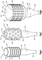
- a collection device 10 for the collecting a biological sample constructed in accordance with the present invention is illustrated in Figs. 1-5 .
- the collection device 10 may be used to collect tissue, cells, protein, RNA and/or DNA from an esophagus of a patient.
- the tissue, cells, protein, RNA and/or DNA collected from the esophagus may be used in any one of the methods disclosed in U.S. Patent Application Serial No. 14/109,041 , U.S. Patent Application Serial No. 13/670,155 , U.S. Patent Application Serial No. 13/263,020 , U.S. Patent No. 8,642,271 , U.S. Patent No. 8,481,707 , U.S. Patent No. 8,415,100 , U.S. Patent No. 8,221,977 , U.S. Patent No. 7,964,353 , and U.S. Patent No. 7,485,420 .
- the collection device 10 includes a generally hollow longitudinally extending collection portion 12.
- the collection portion 12 has a first or proximal axial end portion 14 and a second or distal axial end portion 16.
- the proximal axial end portion 14 and the distal axial end portion 16 may be made of a flexible polymer, such as silicone or polyurethane.
- the distal axial end portion 16 has a lower durometer than the proximal axial end portion 14.
- the distal axial end portion 16 may expand and contract.
- the first or proximal axial end portion 14 is relatively rigid. Therefore, the proximal end portion 14 has a fixed radial extent.
- the first axial end portion 14 and the second axial end portion 16 may be integrally formed as one-piece or may be formed as separate pieces that are connected together in any desire manner.
- the proximal end portion 14 is illustrated as having a cylindrical shape, the proximal end portion may have any desired shape.
- the proximal axial end portion 14 is connected to a support member 20, such as a catheter.
- the support member 20 may be a tubular member in fluid communication with the interior of the collection portion 12.
- the proximal axial end portion 14 conducts fluid, such as air, from the support member 20 to the distal axial end portion 16.
- a proximal end of the support 20 may be connected to a stopcock and syringe to control the injection of fluid to move the distal end portion 16 between the collapsed and expanded positions.
- the support 20 resists collapsing when a vacuum is applied to the support member and resists stretching during withdrawal of the collection device 10 from the collection site.
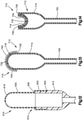
- the second or distal end portion 16 of the collection portion 12 has an expanded or inflated position ( Fig. 1 ) and a collapsed or deflated position ( Figs. 2-3 ).
- the expanded position shown in Fig. 1 may be one of many expanded positions for the distal end portion 16. It is contemplated that the distal end portion 16 may expand more than shown in Fig. 1 so that the distal end portion obtains a more spherical shape and looks similar to a hot air balloon, see Fig. 15 for example.
- the distal end portion 16 has a convex shape, shown in Fig. 1 , when in the expanded or inflated position.
- the distal end portion 16 may extend radially outward a greater distance than the proximal end portion 14 when in the expanded position.
- the distal end portion 16 extends into the first or proximal axial end portion 14 and has a concave shape, shown in Figs. 2 and 3 , when in the collapsed or deflated position.
- the distal end portion 16 may be inverted when in the collapsed position.
- the distal end portion 16 extends axially into the interior of the proximal end portion 14 when in the collapsed or deflated position. Therefore, the distal end portion 16 moves axially or longitudinally relative to the proximal end portion 14 when moving between the deflated and inflated positions.
- the distal end portion 16 may be biased into the collapsed or deflated position in any desired manner.
- the proximal end portion 14 has a relatively high durometer so that the proximal end portion does not collapse when a vacuum is applied to the proximal end portion through the support 20.
- the shape of the proximal end portion 14 does not change when the distal end portion 16 moves between the deflated and inflated positions.
- the proximal end portion 14 does not move radially when the distal end portion 16 moves between the deflated and inflated positions.
- the distal end portion 16 of the collection portion 12 may be connected to the proximal end portion 14 by a circumferentially extending hinge 30.
- the hinge 30 may be a fold.
- the hinge 30 may extend circumferentially around the collection portion 12.
- the hinge 30 defines a distal axial end surface of the collection portion 12 when the distal end portion 16 is in the deflated or collapsed position.
- the distal end portion 16 defines an axial end surface of the collection portion 12 when the distal end portion is in the inflated or expanded position.
- the distal end portion 16 has an outer surface 32 for collecting tissue when the distal portion is in the expanded position.
- the outer surface 32 faces radially outwardly when the distal end portion 16 is in the expanded position and may face radially inwardly when the distal end portion is in the collapsed or inverted position. It is contemplated that the outer surface 32 of the distal end portion 16 may have any desired construction for collecting tissue.
- the outer surface 32 of the distal end portion 16 may have a plurality of projections or bristles 40 for collecting tissue.
- the distal end portion 16 may have any desired number of projections or bristles 40.
- the projections or bristles 40 may have a V-shape ( Fig. 4 ).
- Each projection 40 has a first side 42 and a second side 44 extending from an intersection 48.
- the first and second sides 42, 44 extend in a generally proximal direction from the intersection 48 when the distal end portion 16 is in the expanded position ( Fig. 1 ).
- the first and second sides 42, 44 extend in a generally distal direction when the distal end portion 16 is in the collapsed or inverted position ( Figs. 2 and 3 ).
- the first and second sides 42, 44 define a cup 50 for receiving collected biological samples.
- the cup 50 faces in a proximal direction when the distal portion 16 is in the expanded position and faces in a distal direction when the distal portion is in the collapsed position.
- the first and second sides 42, 44 may extend at an angle of approximately 90° relative to each other. It is contemplated that the first and second sides 42 and 44 may extend at any desired angle relative to each other. The desired angle may be determined based on the type of biological sample to be collected. Alternatively, the projections 40 may be cup shaped or have a semi-circular shape.
- Each of the projections or bristles 40 has side walls 54 and 56 ( Fig. 5 ) that extend radially outward from the outer surface 32 when the distal portion 16 is in the expanded position.
- the side walls 54 and 56 extend from the outer surface 32 to a radially outer surface 58 of the projection 40.
- the side walls 54 and 56 taper toward each other as the side walls extend from the outer surface 32 toward the radially outer surface 58 of the projection 40. It is contemplated that the side walls 54 and 56 may not taper toward each other.
- the distal end portion 16 may include a plurality of projections or bristles 60 ( Fig. 1 ) extending from a distal portion of the distal end portion 16.
- the projections 60 have the same general V-shape as the projections 40 and are smaller than the projections 40.
- the projections 60 have first and second sides 62 and 64 that have a length smaller than the first and second sides 42, 44 of the projections 40.
- the projections or bristles 40, 60 are arranged in circumferentially extending rows ( Fig. 1 ). It is contemplated that each row has six projections 40 or 60. It is contemplated that each of the rows may have any desired number of projections 40 or 60. Each of the projections 40, 60 is circumferentially offset from the projections on an adjacent row. Ribs 66 extend circumferentially between adjacent projections 40, 60 in each row. The ribs 66 extend between ends of the sides walls 54, 56 opposite the intersections 48.
- the collection portion 12 is moved to a collection site within an esophagus, with the distal end portion 16 in the collapsed or deflated position.
- the collection portion 12 is adapted to be swallowed by a patient. It is also contemplated that the patient may be intubated with the collection portion 12 attached to a catheter.
- the distal end portion 16 may be held in the collapsed or deflated position by the hinge 30 and/or by applying a vacuum to the collection portion 12 through the support 20.
- the distal end portion 16 may also be held in the collapsed position by a cap or cover that falls off, pops off and/or dissolves when the collection portion 12 reaches the body lumen.
- the support member 20 or catheter may have depth markings to determine the collection site within the patient's anatomy.
- the distal end portion 16 is moved from the collapsed position to the expanded position when the collection portion 12 is at the collection site.
- a pressurized fluid such as air, may be applied to the distal end portion 16 to cause the distal end portion to move axially from the collapsed position to the expanded position.
- the collection portion 12 is moved in the body lumen to collect a biological sample, such as, tissue, cells, protein, RNA and/or DNA from the collection site when the distal portion is in the expanded position. It is contemplated that the collection portion 12 is only moved in a proximal direction so that the expanded distal end portion 16 engages the collection site to collect biological samples.
- the depth markings on the support member 20 or catheter may be used as a guide.
- the distal end portion 16 is moved from the expanded position to the collapsed or inverted position. The distal end portion 16 may be moved from the expanded position to the collapsed position by applying a vacuum to the collection portion 12.
- the distal end portion 16 does not engage the body lumen and prevents the collected biological samples from being contaminated by tissue from areas along the body lumen different from the collection site.
- the biological samples are collected via a wash and/or the collection portion 12 or the distal end portion 16 may be cut from the support member 20 and deposited in a biological sample vial.
- FIG. 6 A second exemplary embodiment of a collection device constructed in accordance with the present invention is illustrated in Fig. 6 .
- the collection device of Fig. 6 is generally similar to the collection device of Figs. 1-5 . Accordingly, similar numerals will be used to describe similar components.
- a collection device 110 ( Fig. 6 ) includes a generally hollow longitudinally extending collection portion 112.
- the collection portion 112 has a first or proximal axial end portion 114 and a second or distal axial end portion 116.
- the distal axial end portion 116 may expand and contract.
- the proximal end portion 114 is relatively rigid. Therefore, the proximal end portion 114 has a fixed radial extent.
- the first axial end portion 114 and the second axial end portion 116 may be integrally formed as one-piece or may be formed as separate pieces that are connected together in any desired manner.
- the proximal axial end portion 114 is connected to a support member 120, such as a catheter.
- the support member 120 may be a tubular member in fluid communication with the interior of the collection portion 112.
- the proximal end portion 114 conducts fluid, such as air, from the support member 120 to the distal axial end portion 116.
- the second or distal end portion 116 of the collection portion 112 has an expanded or inflated position ( Fig. 6 ) and a collapsed or deflated position similar to the position shown in Figs. 2 and 3 .
- the distal end portion 116 has a convex shape, shown in Fig. 6 , when in the expanded or inflated position.
- the expanded position shown in Fig. 6 may be one of many expanded positions for the distal end portion 116. It is contemplated that the distal end portion 116 may expand more than shown in Fig. 6 so that the distal end portion obtains a more spherical shape and looks similar to a hot air balloon, see Fig. 15 for example.
- the distal end portion 116 extends into the first or proximal end portion 114 and has a concave shape when in the collapsed or deflated position.
- the distal end portion 116 may be biased into the collapsed or deflated position in any desired manner. Therefore, the distal end portion 116 moves axially relative to the proximal end portion 114 when moving between the deflated and inflated positions.
- the shape of the proximal end portion 114 does not change when the distal end portion 116 moves between the deflated and inflated positions.
- the proximal end portion 114 does not move radially when the distal end portion 116 moves between the deflated and inflated positions.
- the distal end portion 116 of the collection portion 112 may be connected to the proximal end portion 114 by a circumferentially extending hinge 130.
- the hinge 130 may be a fold.
- the hinge 130 may extend circumferentially around the collection portion 112.
- the hinge 130 defines a distal axial end surface of the collection portion 112 when the distal end portion 116 is in the deflated or collapsed position.
- the distal end portion 116 defines an axial end surface of the collection portion 112 when the distal end portion is in the inflated or expanded position.
- the distal end portion 116 has an outer surface 132 for collecting biological samples.
- the outer surface 132 of the distal end portion 116 may have a plurality of projections or ribs 140 for collecting biological samples.
- the ribs 140 extend circumferentially around the distal end portion 116 and may extend generally parallel to each other. Although the outer surface 132 is shown as having seven projections or ribs 140, it is contemplated that the outer surface may have any desired number of ribs.
- the ribs 140 may extend radially from the outer surface 132 any distance. It is also contemplated that the ribs 140 may extend different distances from the outer surface 132.
- FIG. 7 A third exemplary embodiment of a collection device constructed in accordance with the present invention is illustrated in Fig. 7 .
- the collection device of Fig. 7 is generally similar to the collection devices of Figs. 1-6 . Accordingly, similar numerals will be used to describe similar components.
- a collection device 210 ( Fig. 7 ) includes a generally hollow longitudinally extending collection portion 212.
- the collection portion 212 has a first or proximal axial end portion 214 and a second or distal axial end portion 216.
- the distal axial end portion 216 may expand and contract.
- the proximal end portion 214 is relatively rigid. Therefore, the proximal end portion 214 has a fixed radial extent.
- the first axial end portion 214 and the second axial end portion 216 may be integrally formed as one-piece or may be formed as separate pieces that are connected together in any desired manner.
- the proximal end portion 214 has a fixed radial extent.
- the proximal axial end portion 214 is connected to a support member 220, such as a catheter.
- the support member 220 may be a tubular member in fluid communication with the interior of the collection portion 212.
- the proximal axial end portion 214 conducts fluid, such as air, from the support member 20 to the distal axial end portion 216.
- the distal end portion 216 of the collection portion 212 has an expanded or inflated position ( Fig. 7 ) and a collapsed or deflated position similar to the position shown in Figs. 2 and 3 .
- the expanded position shown in Fig. 7 may be one of many expanded positions for the distal end portion 216. It is contemplated that the distal end portion 216 may expand more than shown in Fig. 7 so that the distal end portion obtains a more spherical shape and looks similar to a hot air balloon, see Fig. 15 for example.
- the distal end portion 216 has a convex shape, shown in Fig. 7 , when in the expanded or inflated position.
- the distal end portion 216 extends into the proximal end portion 214 and has a concave shape when in the collapsed or deflated position. Therefore, the distal end portion 216 moves axially relative to the proximal end portion 214 when moving between the deflated and inflated positions.
- the distal end portion 216 may be biased into the collapsed or deflated position in any desired manner.
- the shape of the proximal end portion 214 does not change when the distal end portion 216 moves between the deflated and inflated positions.
- the proximal end portion 214 does not move radially when the distal end portion 216 moves between the deflated and inflated positions.
- the distal end portion 216 of the collection portion 212 may be connected to the proximal end portion 214 by a circumferentially extending hinge 230.
- the hinge 230 may be a fold.
- the hinge 230 may extend circumferentially around the collection portion 212.
- the hinge 230 defines a distal axial end surface of the collection portion 212 when the distal end portion 216 is in the deflated or collapsed position.
- the distal end portion 216 defines an axial end surface of the collection portion 212 when the distal end portion is in the inflated or expanded position.
- the distal end portion 216 has an outer surface 232 for collecting biological samples.
- the outer surface 232 of the distal end portion 216 may have a plurality of projections or bristles 240 for collecting biological samples.
- the projections 240 have a generally cylindrical shape.
- the outer surface 232 may have any desired number of projections 240.
- the projections 240 may extend radially from the outer surface 232 any distance. It is also contemplated that the projections 240 may extend different distances from the outer surface 232.
- the projections 240 may have any desired diameters and may have different diameters.
- FIG. 8 and 9 A fourth exemplary embodiment of a collection device constructed in accordance with the present invention is illustrated in Figs. 8 and 9 .
- the collection device of Figs. 8 and 9 is generally similar to the collection devices of Figs. 1-7 . Accordingly, similar numerals will be used to describe similar components.
- a collection device 310 ( Figs. 8-9 ) includes a generally hollow longitudinally extending tissue collection portion 312.
- the collection portion 312 has a first or proximal axial end portion 314 and a second or distal axial end portion 316.
- the distal axial end portion 316 may expand and contract.
- the proximal end portion 314 is relatively rigid. Therefore, the proximal end portion 314 has a fixed radial extent.
- the first axial end portion 314 and the second axial end portion 316 may be integrally formed as one-piece or may be formed as separate pieces that are connected together in any desired manner.
- the proximal end portion 314 has a fixed radial extent.
- the proximal axial end portion 314 is connected to a support member 320, such as a catheter.
- the support member 320 may be a tubular member in fluid communication with the interior of the collection portion 312.
- the proximal axial end portion 314 conducts fluid from the support member 320 to the distal axial end portion 316.
- the distal end portion 316 of the collection portion 312 has an expanded or inflated position ( Fig. 8 ) and a collapsed or deflated position similar to the position shown in Figs. 2 and 3 .
- the expanded position shown in Fig. 8 may be one of many expanded positions for the distal end portion 316. It is contemplated that the distal end portion 316 may expand more than shown in Fig. 8 so that the distal end portion obtains a more spherical shape and looks similar to a hot air balloon, see Fig. 15 for example.
- the distal end portion 316 has a convex shape, shown in Fig. 8 , when in the expanded or inflated position.
- the distal end portion 316 extends into the proximal end portion 314 and has a concave shape when in the collapsed or deflated position. Therefore, the distal end portion 316 moves axially relative to the proximal end portion 314 when moving between the deflated and inflated positions.
- the distal end portion 316 may be biased into the collapsed or deflated position in any desired manner.
- the shape of the proximal end portion 314 does not change when the distal end portion 316 moves between the deflated and inflated positions.
- the proximal end portion 314 does not move radially when the distal end portion 316 moves between the deflated and inflated positions.
- the distal end portion 316 of the collection portion 312 may be connected to the proximal end portion 314 by a circumferentially extending hinge 330.
- the hinge 330 may be a fold.
- the hinge 330 may extend circumferentially around the collection portion 312.
- the hinge 330 defines a distal axial end surface of the collection portion 312 when the distal end portion 316 is in the deflated or collapsed position.
- the distal end portion 316 defines an axial end surface of the collection portion 312 when the distal end portion is in the inflated or expanded position.
- the distal end portion 316 has an outer surface 332 for collecting biological samples.
- the outer surface 332 is generally cylindrical.
- the outer surface 332 has an axially extending surface 334 and an axial end surface 336.
- the axially extending surface 334 of the outer surface 332 may have a plurality of projections or bristles 340 for collecting tissue. It is contemplated that the axial end surface 336 may also include projections 340.
- Each of the projections 340 has a support portion 342 ( Fig. 9 ).
- the support portion 342 may have a bi-directional curve shape or S-shape extending radially outward from the outer surface 332.
- a bi-directional curve shaped or S-shaped portion 344 having a cross-section larger than the support portion 342 extends from the support portion, as shown in Fig. 9 .
- the outer surface 332 may have any desired number of projections 340.
- the projections 340 may extend radially from the outer surface 332 any distance. It is also contemplated that the projections 340 may extend different distances from the outer surface 332.
- FIG. 10 A fifth exemplary embodiment of a collection device constructed in accordance with the present invention is illustrated in Fig. 10 .
- the collection device of Fig. 10 is generally similar to the collection devices of Figs. 1-9 . Accordingly, similar numerals will be used to describe similar components.
- a collection device 410 ( Fig. 10 ) includes a generally hollow longitudinally extending collection portion 412.
- the collection portion 412 has a first or proximal axial end portion 414 and a second or distal axial end portion 416.
- the distal axial end portion 416 may expand and contract.
- the proximal end portion 414 is relatively rigid. Therefore, the proximal end portion 414 has a fixed radial extent.
- the first axial end portion 414 and the second axial end portion 416 may be integrally formed as one-piece or may be formed as separate pieces that are connected together in any desired manner.
- the proximal end portion 414 has a fixed radial extent.
- the proximal axial end portion 414 is connected to a support member 420, such as a catheter.
- the support member 420 may be a tubular member in fluid communication with the interior of the collection portion 412.
- the proximal end portion 414 conducts fluid, such as air, from the support member 420 to the distal axial end portion 416.
- the distal end portion 416 of the collection portion 412 has an expanded or inflated position ( Fig. 10 ) and a collapsed or deflated position similar to the position shown in Figs. 2 and 3 .
- the expanded position shown in Fig. 10 may be one of many expanded positions for the distal end portion 416. It is contemplated that the distal end portion 416 may expand more than shown in Fig. 10 so that the distal end portion obtains a more spherical shape and looks similar to a hot air balloon, see Fig. 15 for example.
- the distal end portion 16 has a convex shape, shown in Fig. 10 , when in the expanded or inflated position.
- the distal end portion 416 extends into the proximal end portion and has a concave shape when in the collapsed or deflated position. Therefore, the distal end portion 416 moves axially relative to the proximal end portion 414 when moving between the deflated and inflated positions.
- the distal end portion 416 may be biased into the collapsed or deflated position in any desired manner.
- the shape of the proximal end portion 414 does not change when the distal end portion 416 moves between the deflated and inflated positions.
- the proximal end portion 414 does not move radially when the distal end portion 416 moves between the deflated and inflated positions.
- the distal end portion 416 of the collection portion 412 may be connected to the proximal end portion 414 by a circumferentially extending hinge 430.
- the hinge 430 may be a fold.
- the hinge 430 may extend circumferentially around the collection portion 412.
- the hinge 430 defines a distal axial end surface of the collection portion 412 when the distal end portion 416 is in the deflated or collapsed position.
- the distal end portion 416 defines an axial end surface of the collection portion 412 when the distal end portion is in the inflated or expanded position.
- the distal end portion 416 has an outer surface 432 for collecting biological samples.
- the outer surface 432 of the distal end portion 416 may have a plurality of projections or bristles 440 for collecting biological samples.
- the projections or bristles 440 may have a V-shape and be generally similar to the V-shaped projections 40 described in connection with the embodiment illustrated in Figs. 1-5 .
- Each projection 440 has a first side 442 and a second side 444 extending in a generally proximal direction from an intersection 448 when the distal end portion 416 is in the expanded position. Therefore, the first and second sides 442, 444 define a proximally facing cup 450 for receiving collected tissue.
- the first and second sides 442, 444 extend at an angle to each other.
- the first and second sides 442, 444 may extend at an angle of approximately 90° relative to each other. It is contemplated that the first and second sides 442 and 444 may extend at any desired angle relative to each other. The desired angle may be determined based on the type of biological sample to be collected.
- the distal end portion 416 may include a plurality of projections or bristles 460 extending from a distal portion of the distal end portion 416.
- the projections 460 have the same general V-shape as the projections 440.
- the projections 460 are smaller than the projections 440 and are located distally to the projections 440 when the distal end portion 416 is in the expanded position.
- FIG. 11 A sixth exemplary embodiment of a collection device constructed in accordance with the present invention is illustrated in Fig. 11 .
- the collection device of Fig. 10 is generally similar to the collection devices of Figs. 1-10 . Accordingly, similar numerals will be used to describe similar components.
- a collection device 510 ( Fig. 11 ) includes a generally hollow longitudinally extending collection portion 512.
- the collection portion 512 has a first or proximal axial end portion 514 and a second or distal axial end portion 516.
- the distal axial end portion 516 may expand and contract.
- the proximal end portion 514 is relatively rigid. Therefore, the proximal end portion 514 has a fixed radial extent.
- the first axial end portion 514 and the second axial end portion 516 may be integrally formed as one-piece or may be formed as separate pieces that are connected together in any desired manner.
- the proximal end portion 514 has a fixed radial extent.
- the proximal axial end portion 514 is connected to a support member 520, such as a catheter.
- the support member 520 may be a tubular member in fluid communication with the interior of the collection portion 512.
- the proximal end portion 514 conducts fluid from the support member 520 to the distal axial end portion 516.
- the distal end portion 516 of the collection portion 512 has an expanded or inflated position ( Fig. 11 ) and a collapsed or deflated position similar to the position shown in Figs. 2 and 3 .
- the expanded position shown in Fig. 11 may be one of many expanded positions for the distal end portion 516. It is contemplated that the distal end portion 516 may expand more than shown in Fig. 11 so that the distal end portion obtains a more spherical shape and looks similar to a hot air balloon, see Fig. 15 for example.
- the distal end portion 16 has a convex shape, shown in Fig. 11 , when in the expanded or inflated position.
- the distal end portion 516 extends into the proximal end portion 514 and has a concave shape when in the collapsed or deflated position. Therefore, the distal end portion 516 moves axially relative to the proximal end portion 514 when moving between the deflated and inflated positions.
- the distal end portion 516 may be biased into the collapsed or deflated position in any desired manner.
- the shape of the proximal end portion 514 does not change when the distal end portion 516 moves between the deflated and inflated positions.
- the proximal end portion 514 does not move radially when the distal end portion 516 moves between the deflated and inflated positions.
- the distal end portion 516 of the collection portion 512 may be connected to the proximal end portion 514 by a circumferentially extending hinge 530.
- the hinge 530 may be a fold.
- the hinge 530 may extend circumferentially around the collection portion 512.
- the hinge 530 defines a distal axial end surface of the collection portion 512 when the distal end portion 516 is in the deflated or collapsed position.
- the distal end portion 516 defines an axial end surface of the collection portion 512 when the distal end portion is in the inflated or expanded position.
- the distal end portion 516 has an outer surface 532 for collecting biological samples.
- the outer surface 532 of the distal end portion 516 may have a plurality of projections or bristles 540 for collecting biological samples.
- the projections or bristles 540 may have an X-shape.
- the distal end portion 516 may include a plurality of projections or bristles 560 extending from a distal portion of the distal end portion 516.
- the projections 560 have the same general X-shape as the projections 540. However, the projections 560 are smaller than the projections 540.
- FIG. 12 A seventh exemplary embodiment of a collection device constructed in accordance with the present invention is illustrated in Fig. 12 .
- the collection device of Fig. 12 is generally similar to the collection devices of Figs. 1-11 . Accordingly, similar numerals will be used to describe similar components.
- a collection device 610 ( Fig. 12 ) includes a generally hollow longitudinally extending collection portion 612.
- the collection portion 612 has a first or proximal axial end portion 614 and a second or distal axial end portion 616.
- the distal axial end portion 616 may expand and contract.
- the proximal end portion 614 is relatively rigid. Therefore, the proximal end portion 614 has a fixed radial extent.
- the proximal axial end portion 614 is connected to a support member, such as a catheter.
- the support member may be a tubular member in fluid communication with the interior of the collection portion 612.
- the proximal end portion 614 conducts fluid from the support member to the distal end portion 616.
- the distal end portion 616 has a first axial end portion 622 connected to the proximal axial end portion 614.
- the first end portion 622 may be connected to the proximal end portion 614 in any desired manner, such as by using an adhesive.
- the first axial end portion 622 engages a shoulder 624 on the proximal axial end portion 614. Therefore, the collection portion 612 has a smooth outer surface.
- the distal end portion 616 of the collection portion 612 has an expanded or inflated position ( Fig. 12 ) and a collapsed or deflated position similar to the position shown in Figs. 2 and 3 .
- the expanded position shown in Fig. 12 may be one of many expanded positions for the distal end portion 616. It is contemplated that the distal end portion 616 may expand more than shown in Fig. 12 so that the distal end portion obtains a more spherical shape and looks similar to a hot air balloon, see Fig. 15 for example.
- the distal end portion 16 has a convex shape, shown in Fig. 12 , when in the expanded or inflated position.
- the distal end portion 616 extends into the proximal end portion 614 and has a concave shape when in the collapsed or deflated position. Therefore, the distal end portion 616 moves axially relative to the proximal end portion 614 when moving between the deflated and inflated positions.
- the distal end portion 616 may be biased into the collapsed or deflated position in any desired manner.
- the shape of the proximal end portion 614 does not change when the distal end portion 616 moves between the deflated and inflated positions.
- the proximal end portion 614 does not move radially when the distal end portion 616 moves between the deflated and inflated positions.
- the distal end portion 616 of the collection portion 612 may be connected to the proximal end portion 614 at a circumferentially extending hinge 630.
- the hinge 630 may extend circumferentially around the collection portion 612.
- the hinge 630 defines a distal axial end surface of the collection portion 612 when the distal end portion 616 is in the deflated or collapsed position.
- the distal end portion 616 defines an axial end surface of the collection portion 612 when the distal end portion is in the inflated or expanded position.
- the distal end portion 616 has an outer surface 632 for collecting biological samples. It is contemplated that the outer surface 632 of the distal end portion 616 may have any desired construction for collecting biological samples.
- the outer surface 632 of the distal end portion 616 may have a plurality of projections or bristles for collecting biological samples.
- the projections or bristles may have any desired shape, such as the shapes shown in Figs. 1-11 .
- FIG. 13-14 An eighth exemplary embodiment of a collection device constructed in accordance with the present invention is illustrated in Figs. 13-14 .
- the collection device of Figs. 13-14 is generally similar to the collection devices of Figs. 1-12 . Accordingly, similar numerals will be used to describe similar components.
- a collection device 710 ( Fig. 11 ) includes a generally hollow longitudinally extending collection portion 712.
- the collection portion 712 has a first or proximal axial end portion 714 and a second or distal axial end portion 716.
- the distal axial end portion 716 may expand and contract.
- the proximal end portion 714 is relatively rigid. Therefore, the proximal end portion 714 has a fixed radial extent.
- the first axial end portion 714 and the second axial end portion 716 may be integrally formed as one-piece or may be formed as separate pieces that are connected together in any desired manner.
- the proximal end portion 714 has a fixed radial extent.
- the proximal axial end portion 714 is connected to a support member 720.
- the support member 720 may be a tubular member in fluid communication with the interior of the collection portion 712.
- the proximal end portion 714 conducts fluid from the support member 720 to the distal end portion 716.
- the distal end portion 716 of the collection portion 712 has an expanded or inflated position ( Fig. 13 ) and a collapsed or deflated position ( Fig. 14 ).
- the expanded position shown in Fig. 13 may be one of many expanded positions for the distal end portion 716. It is contemplated that the distal end portion 716 may expand more than shown in Fig. 13 so that the distal end portion obtains a more spherical shape and looks similar to a hot air balloon, see Fig. 15 for example.
- the distal end portion 716 has a convex shape, shown in Fig. 13 , when in the expanded or inflated position.
- the distal end portion 716 extends into the proximal end portion 714 and has a concave shape when in the collapsed or deflated position, as shown in Fig. 14 .
- the distal end portion 716 only moves axially relative to the proximal end portion 714 when moving between the deflated and inflated positions.
- the distal end portion 716 may be biased into the collapsed or deflated position in any desired manner.
- the shape of the proximal end portion 714 does not change when the distal end portion 716 moves between the deflated and inflated positions.
- the proximal end portion 714 does not move radially when the distal end portion716 moves between the deflated and inflated positions.
- the distal end portion 716 of the collection portion 712 may be connected to the proximal end portion 714 by a circumferentially extending hinge 730.
- the hinge 730 may be a fold.
- the hinge 730 may extend circumferentially around the collection portion 712.
- the hinge 730 defines a distal axial end surface of the collection portion 712 when the distal end portion 716 is in the deflated or collapsed position.
- the distal end portion 716 defines an axial end surface of the collection portion 712 when the distal end portion is in the inflated or expanded position.
- the distal end portion 716 has an outer surface 732 for collecting biological samples. It is contemplated that the outer surface 732 of the distal end portion 716 may have any desired construction for collecting biological samples.
- the outer surface 732 of the distal end portion 716 may have a plurality of projections or bristles 740 for collecting biological samples.
- the outer surface 732 may have any desired number of projections 740.
- FIG. 15 A ninth exemplary embodiment of a collection device constructed in accordance with the present invention is illustrated in Fig. 15 .
- the collection device of Fig. 15 is generally similar to the collection device of Figs. 1-14 . Accordingly, similar numerals will be used to describe similar components.
- a collection device 810 ( Fig. 15 ) includes a generally hollow longitudinally extending collection portion 812.
- the collection portion 812 has a first or proximal axial end portion 814 and a second or distal axial end portion 816.
- the distal axial end portion 816 may expand and contract.
- the proximal end portion 814 is relatively rigid. Therefore, the proximal end portion 814 has a fixed radial extent.
- the first axial end portion 814 and the second axial end portion 816 may be integrally formed as one-piece or may be formed as separate pieces that are connected together in any desired manner.
- the proximal axial end portion 814 is connected to a support member 820, such as a catheter.
- the support member 820 may be a tubular member in fluid communication with the interior of the collection portion 812.
- the proximal end portion 814 conducts fluid, such as air, from the support member 820 to the distal axial end portion 816.
- the second or distal end portion 816 of the collection portion 812 has an expanded or inflated position ( Fig. 15 ) and a collapsed or deflated position similar to the position shown in Figs. 2 and 3 .
- the distal end portion 816 has a convex shape, shown in Fig. 15 , when in the expanded or inflated position.
- the expanded position shown in Fig. 15 may be one of many expanded positions for the distal end portion 816. It is contemplated that the distal end portion 816 may expand less than shown in Fig. 15 so that the distal end portion obtains a more oblong shape and looks similar to the distal end portion 16 shown in Fig. 1 .
- the distal end portion 816 extends into the first or proximal end portion 814 and has a concave shape when in the collapsed or deflated position.
- the distal end portion 816 may be biased into the collapsed or deflated position in any desired manner. Therefore, the distal end portion 816 moves axially relative to the proximal end portion 814 when moving between the deflated and inflated positions.
- the shape of the proximal end portion 814 does not change when the distal end portion 816 moves between the deflated and inflated positions.
- the proximal end portion 814 does not move radially when the distal end portion 816 moves between the deflated and inflated positions.
- the distal end portion 816 of the collection portion 812 may be connected to the proximal end portion 814 by a circumferentially extending hinge 830.
- the hinge 830 may be a fold.
- the hinge 830 may extend circumferentially around the collection portion 812.
- the hinge 830 defines a distal axial end surface of the collection portion 812 when the distal end portion 816 is in the deflated or collapsed position.
- the distal end portion 816 defines an axial end surface of the collection portion 812 when the distal end portion is in the inflated or expanded position.
- the distal end portion 816 has an outer surface 832 for collecting biological samples.
- the outer surface 832 of the distal end portion 816 may have a textured surface or include a plurality of projections or ribs for collecting biological samples..
- Each of the collection portions of the described collection devices is moved to a collection site within an esophagus, with the distal end portion in the collapsed or deflated position.
- the collection portion is adapted to be swallowed by a patient.
- the distal end portion may be held in the collapsed or deflated position by the hinge and/or by applying a vacuum to the collection portion through the support.
- the distal end portion may also be held in the collapsed position by a cap or cover that falls off, pops off and/or dissolves when the collection portion reaches the collection site.
- the distal end portion is moved from the collapsed position to the expanded position when the collection portion is at the collection site.
- the collection portion is moved in the body lumen to collect biological samples, such as, tissue, cells, protein, RNA and/or DNA from the collection site when the distal portion is in the expanded position.
- biological samples such as, tissue, cells, protein, RNA and/or DNA from the collection site when the distal portion is in the expanded position.
- the distal end portion is moved from the expanded position to the collapsed position. As the collection portion moves out of the body lumen, the distal end portion does not engage the body lumen and prevents the collected biological samples from being contaminated by tissue from areas along the body lumen different from the collection site.
- the collection devices described above may be formed as one-piece or formed as separate pieces that are connected together. Also, it is contemplated that the projections or bristles may have any desired shape. Accordingly, the tissue collection devices may have at least one V-shaped projection and/or at least one circumferentially extending rib and/or at least one cylindrical projection and/or at least one bi-directional curved shaped projection and/or at least one X-shaped projection. It is also contemplated that each of the collection devices may have circumferentially extending ribs extending between adjacent projections.
Landscapes
- Health & Medical Sciences (AREA)
- Life Sciences & Earth Sciences (AREA)
- Medical Informatics (AREA)
- Engineering & Computer Science (AREA)
- Biomedical Technology (AREA)
- Heart & Thoracic Surgery (AREA)
- Pathology (AREA)
- Molecular Biology (AREA)
- Surgery (AREA)
- Animal Behavior & Ethology (AREA)
- General Health & Medical Sciences (AREA)
- Public Health (AREA)
- Veterinary Medicine (AREA)
- Media Introduction/Drainage Providing Device (AREA)
- Sampling And Sample Adjustment (AREA)
Claims (15)
- Ösophagus-Probenentnahmevorrichtung (10) zur Entnahme einer biologischen Probe aus dem Ösophagus eines Patienten, wobei die Vorrichtung (10) einen Entnahmeabschnitt (12) umfasst, eingerichtet zum Anbringen an einem Trägerelement (20) und zum Schlucken von einem Patienten, wobei der Entnahmeabschnitt (12) einen ersten axialen Endabschnitt (14) und einen zweiten axialen Endabschnitt (16) zur Entnahme der biologischen Probe darauf aufweist, wobei der zweite axiale Endabschnitt (16) eine zusammengeklappte Position und eine entfaltete Position aufweist, wobei der zweite axiale Endabschnitt (16) so ausgelegt ist, dass er sich als Reaktion auf einen durch das Trägerelement (20) aufgebrachten Fluiddruck in einer axialen Richtung relativ zum ersten axialen Endabschnitt (14) von der zusammengeklappten Position zur entfalteten Position bewegt, um die biologische Probe zu entnehmen.
- Ösophagus-Probenentnahmevorrichtung (10) zur Entnahme einer biologischen Probe nach Anspruch 1, wobei sich der zweite axiale Endabschnitt (16) axial in den ersten axialen Endabschnitt (14) erstreckt und eine konkave Form aufweist, wenn sich der zweite axiale Endabschnitt (16) in der zusammengeklappten Position befindet.
- Ösophagus-Probenentnahmevorrichtung (10) zur Entnahme einer biologischen Probe nach Anspruch 1, wobei der zweite axiale Endabschnitt (16) eine äußere Oberfläche (32) aufweist, die radial nach außen gerichtet ist, wenn sich der zweite axiale Endabschnitt (16) im entfalteten Zustand befindet, wobei die äußere Oberfläche (32) radial nach innen weist, wenn sich der zweite axiale Endabschnitt (16) in der zusammengeklappten Position befindet.
- Ösophagus-Probenentnahmevorrichtung (10) zur Entnahme einer biologischen Probe nach Anspruch 1, wobei der zweite axiale Endabschnitt (16) eine Vielzahl von Gewebeentnahmevorsprüngen (40, 60) beinhaltet.
- Ösophagus-Probenentnahmevorrichtung (10) zur Entnahme einer biologischen Probe nach Anspruch 4, wobei mindestens einer der Gewebeentnahmevorsprünge (40, 60) eine V-Form aufweist.
- Ösophagus-Probenentnahmevorrichtung (10) zur Entnahme einer biologischen Probe nach Anspruch 5, wobei der mindestens eine der Gewebeentnahmevorsprünge (40, 60) eine erste (42) und eine zweite (44) Seite aufweist, die sich von einem Schnittpunkt (48) in einem Winkel zueinander erstrecken, wobei sich die erste und die zweite Seite (42, 44) von dem Schnittpunkt (48) in Richtung des ersten axialen Endabschnitts (14) erstrecken, wenn sich der zweite axiale Endabschnitt (16) in der entfalteten Position befindet.
- Ösophagus-Probenentnahmevorrichtung (10) zur Entnahme einer biologischen Probe nach Anspruch 4, wobei sich in Umfangsrichtung erstreckende Rippen (66) zwischen benachbarten Gewebeentnahmevorsprüngen (40, 60) erstrecken.
- Ösophagus-Probenentnahmevorrichtung (10) zur Entnahme einer biologischen Probe nach Anspruch 4, wobei sich die Seitenwände (54, 56) der Gewebeentnahmevorsprünge (40, 60) zueinander verjüngen, wenn sich die Seitenwände (54, 56) vom zweiten Endabschnitt (16) radial nach außen erstrecken.
- Ösophagus-Probenentnahmevorrichtung (10) zur Entnahme einer biologischen Probe nach Anspruch 4, wobei die Vielzahl von Gewebeentnahmevorsprüngen mindestens eine sich in Umfangsrichtung erstreckende Rippe (140) beinhaltet.
- Ösophagus-Probenentnahmevorrichtung (10) zur Entnahme einer biologischen Probe nach Anspruch 4, wobei die Vielzahl von Gewebeentnahmevorsprüngen mindestens einen sich radial erstreckenden zylindrischen Vorsprung (240) beinhaltet.
- Ösophagus-Probenentnahmevorrichtung (10) zur Entnahme einer biologischen Probe nach Anspruch 4, wobei die Vielzahl von Gewebeentnahmevorsprüngen mindestens einen bidirektional gekrümmten Vorsprung (340) beinhaltet, wobei der mindestens eine bidirektional gekrümmte Vorsprung (340) vorzugsweise einen Stützabschnitt (342), der sich von dem zweiten axialen Endabschnitt (316) radial nach außen erstreckt, und einen bidirektional gekrümmten Abschnitt (344) mit einem größeren Querschnitt als der Stützabschnitt (342) beinhaltet.
- Ösophagus-Probenentnahmevorrichtung (10) zur Entnahme einer biologischen Probe nach Anspruch 4, wobei die Vielzahl von Gewebeentnahmevorsprüngen mindestens einen X-förmigen Vorsprung (540) enthält.
- Ösophagus-Probenentnahmevorrichtung (10) zur Entnahme einer biologischen Probe nach Anspruch 1, wobei der erste und der zweite axiale Endabschnitt integral als ein Stück ausgebildet sind, oder wobei der erste und der zweite axiale Endabschnitt als gesonderte Stücke ausgebildet und miteinander verbunden sind.
- Ösophagus-Probenentnahmevorrichtung (10) zur Entnahme einer biologischen Probe nach Anspruch 1, wobei der erste und der zweite axiale Endabschnitt (14, 16) durch ein sich in Umfangsrichtung erstreckendes Gelenk (30) verbunden sind.
- Vorrichtung zur Entnahme einer biologischen Probe aus dem Ösophagus eines Patienten, umfassend:ein Trägerelement (20), das vorzugsweise ein Katheter ist; unddie Ösophagus-Probenentnahmevorrichtung (10) nach einem der Ansprüche 1 bis 14.
Priority Applications (2)
| Application Number | Priority Date | Filing Date | Title |
|---|---|---|---|
| EP19208108.1A EP3622894B1 (de) | 2013-12-12 | 2014-12-12 | Vorrichtung zur entnahme einer biologischen probe |
| EP24178269.7A EP4437972A3 (de) | 2013-12-12 | 2014-12-12 | Vorrichtung zur entnahme einer biologischen probe |
Applications Claiming Priority (2)
| Application Number | Priority Date | Filing Date | Title |
|---|---|---|---|
| US201361915029P | 2013-12-12 | 2013-12-12 | |
| PCT/US2014/070060 WO2015089422A1 (en) | 2013-12-12 | 2014-12-12 | Device for collecting a biological sample |
Related Child Applications (3)
| Application Number | Title | Priority Date | Filing Date |
|---|---|---|---|
| EP19208108.1A Division-Into EP3622894B1 (de) | 2013-12-12 | 2014-12-12 | Vorrichtung zur entnahme einer biologischen probe |
| EP19208108.1A Division EP3622894B1 (de) | 2013-12-12 | 2014-12-12 | Vorrichtung zur entnahme einer biologischen probe |
| EP24178269.7A Division EP4437972A3 (de) | 2013-12-12 | 2014-12-12 | Vorrichtung zur entnahme einer biologischen probe |
Publications (3)
| Publication Number | Publication Date |
|---|---|
| EP3079598A1 EP3079598A1 (de) | 2016-10-19 |
| EP3079598A4 EP3079598A4 (de) | 2017-11-15 |
| EP3079598B1 true EP3079598B1 (de) | 2022-03-16 |
Family
ID=53371874
Family Applications (3)
| Application Number | Title | Priority Date | Filing Date |
|---|---|---|---|
| EP14870556.9A Active EP3079598B1 (de) | 2013-12-12 | 2014-12-12 | Vorrichtung zur entnahme einer biologischen probe |
| EP24178269.7A Withdrawn EP4437972A3 (de) | 2013-12-12 | 2014-12-12 | Vorrichtung zur entnahme einer biologischen probe |
| EP19208108.1A Active EP3622894B1 (de) | 2013-12-12 | 2014-12-12 | Vorrichtung zur entnahme einer biologischen probe |
Family Applications After (2)
| Application Number | Title | Priority Date | Filing Date |
|---|---|---|---|
| EP24178269.7A Withdrawn EP4437972A3 (de) | 2013-12-12 | 2014-12-12 | Vorrichtung zur entnahme einer biologischen probe |
| EP19208108.1A Active EP3622894B1 (de) | 2013-12-12 | 2014-12-12 | Vorrichtung zur entnahme einer biologischen probe |
Country Status (5)
| Country | Link |
|---|---|
| US (8) | US10660621B2 (de) |
| EP (3) | EP3079598B1 (de) |
| AU (2) | AU2014361829B2 (de) |
| CA (2) | CA2933550C (de) |
| WO (1) | WO2015089422A1 (de) |
Families Citing this family (29)
| Publication number | Priority date | Publication date | Assignee | Title |
|---|---|---|---|---|
| WO2014121207A1 (en) | 2013-02-01 | 2014-08-07 | Nvision Medical Corporation | Methods and devices for fallopian tube diagnostics |
| US10639016B2 (en) | 2013-02-01 | 2020-05-05 | Boston Scientific Scimed, Inc. | Methods and devices for Fallopian tube diagnostics |
| EP3079598B1 (de) | 2013-12-12 | 2022-03-16 | Case Western Reserve University | Vorrichtung zur entnahme einer biologischen probe |
| GB201415653D0 (en) * | 2014-09-04 | 2014-10-22 | Univ Leeds | Orthopaedic medical device |
| HU230970B1 (hu) * | 2015-08-31 | 2019-06-28 | Dolhay Kft. | Váladék mintavevő eszköz |
| US20170112477A1 (en) * | 2015-10-21 | 2017-04-27 | Boston Scientific Scimed, Inc. | Tissue sample device and methods |
| AU2017224147B2 (en) * | 2016-02-25 | 2019-03-28 | Boston Scientific Scimed, Inc. | Methods and devices for fallopian tube diagnostics |
| US12258632B2 (en) | 2016-07-06 | 2025-03-25 | Case Western Reserve University | Methods and compositions for detecting esophageal neoplasias and/or metaplasias in the esophagus |
| EP3618724A4 (de) * | 2017-05-03 | 2021-05-05 | Case Western Reserve University | Vorrichtung zur entnahme einer biologischen probe |
| US20180344300A1 (en) * | 2017-05-31 | 2018-12-06 | 4Women Health, Inc. | Self-collection device and kit for collecting cervical and vaginal cells |
| CN108209980B (zh) * | 2018-01-25 | 2021-05-11 | 山东省日照市人民医院 | 一种消化内科诊断用取样装置 |
| AU2020283954B2 (en) | 2019-05-28 | 2026-04-30 | Case Western Reserve University | Compositions and methods for preserving DNA methylation |
| US11878116B2 (en) * | 2019-11-01 | 2024-01-23 | Iowa State University Research Foundation, Inc. | Tracheo-bronchial sampling device |
| WO2021242872A1 (en) | 2020-05-27 | 2021-12-02 | Case Western Reserve University | Compositions and methods for preserving dna methylation |
| WO2021237293A1 (en) * | 2020-05-27 | 2021-12-02 | 3DMEDiTech Pty Ltd | Swab |
| JP2023527549A (ja) | 2020-05-27 | 2023-06-29 | ケース ウエスタン リザーブ ユニバーシティ | 生物試料採取装置 |
| US12262879B2 (en) | 2020-06-16 | 2025-04-01 | Case Western Reserve University | Device for biological cell collection and method of use |
| CA3186131A1 (en) * | 2020-06-16 | 2021-12-23 | Case Western Reserve University | Device for biological cell collection and method of use |
| US20230363745A1 (en) * | 2020-09-16 | 2023-11-16 | Bionlifescience, Inc. | Sample collection stick |
| WO2022104433A1 (en) * | 2020-11-19 | 2022-05-27 | 3DMEDiTech Pty Ltd | Mucus collection device |
| EP4029456A1 (de) * | 2021-01-14 | 2022-07-20 | Albireo Biomedical sp. z o.o. | Stift zum sammeln und überführen von biologischem material |
| US20220287694A1 (en) * | 2021-03-09 | 2022-09-15 | Jovanni Neblett-Blackmon | Comfortable Patient Collected Home PAP |
| CN113017714B (zh) * | 2021-03-15 | 2021-11-16 | 深圳市康达安生物科技有限公司 | 一种宫颈刷及其宫颈刷的制造工艺 |
| US20230000475A1 (en) * | 2021-07-02 | 2023-01-05 | Case Western Reserve University | Biological sampling device and method of use |
| US20230000474A1 (en) * | 2021-07-02 | 2023-01-05 | Case Western Reserve University | Biological sampling device and method of use |
| WO2023010006A1 (en) | 2021-07-27 | 2023-02-02 | PAVmed Inc. | Catheter status indicator and methods of use |
| CN113995447A (zh) * | 2021-11-05 | 2022-02-01 | 上海科罡医疗技术有限公司 | 球囊状生物采样器 |
| US12089825B2 (en) | 2022-06-28 | 2024-09-17 | Brent Harris | Devices and methods with expandable brush for cervical and anal self-collecting specimens |
| WO2025241037A1 (es) * | 2024-05-20 | 2025-11-27 | Pontificia Universidad Católica De Chile | Dispositivo de automuestreo para la recolección de fluido cervico-vaginal |
Citations (3)
| Publication number | Priority date | Publication date | Assignee | Title |
|---|---|---|---|---|
| US4481952A (en) * | 1978-03-22 | 1984-11-13 | Jerzy Pawelec | Device for the study of the alimentary canal |
| WO1987005523A1 (en) * | 1986-03-13 | 1987-09-24 | Siemens, Herman, Werner | Tubular devices for introduction into body orifices |
| US4735214A (en) * | 1986-09-05 | 1988-04-05 | Berman Irwin R | Gastrointestinal diagnostic capsule and method of use |
Family Cites Families (90)
| Publication number | Priority date | Publication date | Assignee | Title |
|---|---|---|---|---|
| US1098222A (en) * | 1913-10-29 | 1914-05-26 | Edward F Heffner | Sanitary medicament-ejector for rectal, vaginal, and nasal use. |
| US2701559A (en) * | 1951-08-02 | 1955-02-08 | William A Cooper | Apparatus for exfoliating and collecting diagnostic material from inner walls of hollow viscera |
| US3400708A (en) * | 1965-11-24 | 1968-09-10 | Robert A. Scheidt | Cytologic endocrine evaluation device |
| US3664328A (en) * | 1971-04-28 | 1972-05-23 | Henry Dinwoodey Moyle Jr | Cancer test specimen gathering device |
| ZA761847B (en) | 1976-03-26 | 1977-10-26 | A Baskind | Detection of oesophageal cancer |
| DE2812709C2 (de) | 1978-03-23 | 1982-08-19 | Battelle-Institut E.V., 6000 Frankfurt | Vorrichtung zur Gewinnung von Zellmaterialien aus Körperhöhlen |
| JPS5964065A (ja) | 1982-10-04 | 1984-04-11 | テルモ株式会社 | バル−ンカテ−テル |
| JPS6052817A (ja) | 1983-09-02 | 1985-03-26 | Olympus Optical Co Ltd | 内視鏡の試料採取器具 |
| US4979951A (en) | 1984-05-30 | 1990-12-25 | Simpson John B | Atherectomy device and method |
| US4627444A (en) | 1985-06-20 | 1986-12-09 | Regents Of The University Of Minnesota | Device for sampling tissues and fluids from bodily cavities |
| WO1989006360A1 (fr) * | 1988-01-11 | 1989-07-13 | Elmex Ltd. | Eprouvette pour le traitement automatique de matieres fecales |
| US5318587A (en) | 1989-08-25 | 1994-06-07 | C. R. Bard, Inc. | Pleated balloon dilatation catheter and method of use |
| US5879499A (en) | 1996-06-17 | 1999-03-09 | Heartport, Inc. | Method of manufacture of a multi-lumen catheter |
| WO1994023787A1 (en) * | 1993-04-22 | 1994-10-27 | Rammler David H | Sampling balloon catheter |
| US5445164A (en) * | 1993-05-11 | 1995-08-29 | Gynetech, Inc. | Cervical tissue sampling device |
| US20060271061A1 (en) | 2001-07-25 | 2006-11-30 | Disc-O-Tech, Ltd. | Deformable tools and implants |
| US8068897B1 (en) * | 1999-03-01 | 2011-11-29 | Gazdzinski Robert F | Endoscopic smart probe and method |
| CA2363250A1 (en) * | 1999-03-09 | 2000-09-14 | Advance Sentry Corporation | Biopsy apparatus and method of obtaining biopsy sample |
| AU3749400A (en) | 1999-03-16 | 2000-10-04 | Chase Medical Inc. | Catheter having varying resiliency balloon |
| US6786889B1 (en) | 1999-03-31 | 2004-09-07 | Scimed Life Systems, Inc | Textured and/or marked balloon for stent delivery |
| DE60212821T2 (de) | 2001-04-16 | 2007-02-01 | Cytyc Corp., Marlborough | Medizinisches instrument mit atraumatischer spitze |
| US7004913B1 (en) * | 2001-05-04 | 2006-02-28 | Cdx Laboratories, Inc. | Retractable brush for use with endoscope for brush biopsy |
| US7108661B2 (en) | 2001-05-07 | 2006-09-19 | United States Endoscopy Group, Inc. | Method and collection device for Barrett's esophagus cells |
| GB2379389B (en) | 2001-09-06 | 2005-03-30 | Mediplus Ltd | Multi-lumen manometry catheters |
| US20040127932A1 (en) * | 2002-09-12 | 2004-07-01 | Shah Tilak M. | Dip-molded polymeric medical devices with reverse thickness gradient, and method of making same |
| EP1660683B1 (de) | 2003-08-14 | 2017-04-19 | Case Western Reserve University | Verfahren und zusammensetzungen zum nachweis von kolonkarzinomen |
| US8415100B2 (en) | 2003-08-14 | 2013-04-09 | Case Western Reserve University | Methods and compositions for detecting gastrointestinal and other cancers |
| JP3852033B2 (ja) | 2003-12-12 | 2006-11-29 | 独立行政法人科学技術振興機構 | 能動チューブおよび能動チューブシステム |
| US20050215959A1 (en) | 2004-03-24 | 2005-09-29 | Children's Memorial Hospital. | Delivery devices and methods of delivering liquids and nutrition to patients |
| US9339259B2 (en) | 2004-07-07 | 2016-05-17 | Colonix Limited | Colorectal cell sampling device |
| GB0415277D0 (en) * | 2004-07-07 | 2004-08-11 | Colonix Ltd | Apparatus and method for sampling mucosal surfaces |
| JP4982637B2 (ja) | 2004-12-15 | 2012-07-25 | クック メディカル テクノロジーズ エルエルシー | 可撓性手術針デバイス |
| US20060184191A1 (en) | 2005-02-11 | 2006-08-17 | Boston Scientific Scimed, Inc. | Cutting balloon catheter having increased flexibility regions |
| JP2008541851A (ja) | 2005-05-27 | 2008-11-27 | アメディカ コーポレイション | セラミックの脛骨部品を有する人工膝関節 |
| GB0521521D0 (en) | 2005-10-21 | 2005-11-30 | Medical Res Council | Diagnostic methods and kits |
| US8038595B2 (en) | 2006-01-25 | 2011-10-18 | Beth Israel Deaconess Medical Center | Devices and methods for tissue transplant and regeneration |
| JP4088692B2 (ja) | 2006-02-23 | 2008-05-21 | 国立大学法人山口大学 | スタイレット |
| CN2882539Y (zh) | 2006-02-27 | 2007-03-28 | 黄晶 | 体腔超声硬度成像仪 |
| JP5512271B2 (ja) | 2006-10-10 | 2014-06-04 | バイオセンス・ウエブスター・インコーポレーテツド | 食道マッピングカテーテル |
| US20080188769A1 (en) * | 2007-02-07 | 2008-08-07 | Li-Cheng Lu | Foldable Brush Self-sampling Device |
| US8840566B2 (en) * | 2007-04-02 | 2014-09-23 | University Of Washington | Catheter with imaging capability acts as guidewire for cannula tools |
| WO2008131033A1 (en) | 2007-04-16 | 2008-10-30 | Orasure Technologies, Inc. | Sample collector |
| US20090118641A1 (en) | 2007-11-02 | 2009-05-07 | Jacques Van Dam | Devices, Methods, and Kits for a Biopsy Device |
| AU2008340875A1 (en) | 2007-12-21 | 2009-07-02 | Coloplast A/S | Diameter-controlled balloon catheter |
| US20090299327A1 (en) | 2008-06-02 | 2009-12-03 | Lorna Vista Medical, Inc. | Inflatable medical devices |
| US20110071428A1 (en) | 2008-08-01 | 2011-03-24 | The Penn State Research Foundation | Biopsy device |
| EP3327139A1 (de) | 2009-04-06 | 2018-05-30 | The Johns Hopkins University | Digitale quantifizierung der dna-methylierung |
| US20100286593A1 (en) | 2009-05-11 | 2010-11-11 | Hotspur Technologies, Inc. | Balloon catheter with cutting features and methods for use |
| US8642271B2 (en) | 2009-08-27 | 2014-02-04 | Case Western Reserve University | Aberrant methylation of C6Orf150 DNA sequences in human colorectal cancer |
| WO2011116481A1 (en) * | 2010-03-25 | 2011-09-29 | Dna Genotek Inc. | Sample collection tool |
| GB201105622D0 (en) | 2011-04-01 | 2011-05-18 | Phangenesis Ltd | Multi functional catheter |
| CN202104944U (zh) | 2011-05-19 | 2012-01-11 | 麦克奥迪(厦门)医疗诊断系统有限公司 | 一次性食道脱落细胞取样器 |
| WO2012162610A1 (en) | 2011-05-26 | 2012-11-29 | Adn International, Llc | Expandable device for tissue collection from an aerodigestive body lumen |
| ES2791766T3 (es) | 2011-09-13 | 2020-11-05 | Pigott John P | Catéter intravascular que tiene una porción de incisión expansible |
| JP6117209B2 (ja) | 2011-09-14 | 2017-04-19 | ボストン サイエンティフィック サイムド,インコーポレイテッドBoston Scientific Scimed,Inc. | 複数のアブレーションモードを備えたアブレーション装置及び同アブレーション装置を含むシステム |
| US9861444B2 (en) | 2011-11-01 | 2018-01-09 | The Johns Hopkins University | Method and device for endoscopic abrasion |
| GB201120162D0 (en) | 2011-11-22 | 2012-01-04 | Medical Res Council | Methods for detection of benign conditions |
| WO2013116560A1 (en) | 2012-01-31 | 2013-08-08 | The Trustees Of Columbia University In The City Of New York | Tissue sampling devices, methods, and systems |
| US20150057517A1 (en) | 2012-03-27 | 2015-02-26 | University Of Utah Research Foundation | Sample capture device and systems and methods of using same |
| US20130267870A1 (en) * | 2012-04-06 | 2013-10-10 | Histologics Llc | Cell and tissue collection method and device |
| US9351779B2 (en) | 2013-01-25 | 2016-05-31 | Kyphon SÀRL | Expandable device and methods of use |
| WO2014121207A1 (en) | 2013-02-01 | 2014-08-07 | Nvision Medical Corporation | Methods and devices for fallopian tube diagnostics |
| US8668654B1 (en) | 2013-03-13 | 2014-03-11 | Sanovas, Inc. | Cytological brushing system |
| WO2014144467A1 (en) | 2013-03-15 | 2014-09-18 | Abbott Cardiovascular Systems Inc. | Reduced material tip for catheter and method of forming same |
| AT514209B1 (de) | 2013-04-16 | 2015-02-15 | Mitterer Stephan | Vorrichtung zur Probennahme |
| EP3079598B1 (de) | 2013-12-12 | 2022-03-16 | Case Western Reserve University | Vorrichtung zur entnahme einer biologischen probe |
| JP6314612B2 (ja) | 2014-04-03 | 2018-04-25 | ニプロ株式会社 | 胃内到達確認具 |
| WO2015157727A2 (en) | 2014-04-10 | 2015-10-15 | Avendo Imaging Systems | Tethered endoscope |
| GB201415653D0 (en) * | 2014-09-04 | 2014-10-22 | Univ Leeds | Orthopaedic medical device |
| US10751033B2 (en) | 2014-09-18 | 2020-08-25 | Covidien Lp | Use of expansion-force elements in a compressible cell collection device |
| WO2016176403A1 (en) | 2015-04-28 | 2016-11-03 | Nosler Michael | Stylet and needle combinations used to collect tissue samples during endoscopic procedures |
| GB2538088B (en) | 2015-05-06 | 2019-01-16 | Caldbeck Overseas Ltd | Clinical sampling device |
| EP3294160B1 (de) | 2015-05-14 | 2022-04-20 | Cook Medical Technologies, LLC | Endoskopischer nadelführungsstab mit längen mit erhöhter flexibilität |
| US20180146839A1 (en) | 2015-06-24 | 2018-05-31 | The Regents Of The University Of Colorado, A Body Corporate | Multi-use scope |
| JP6753655B2 (ja) | 2015-08-21 | 2020-09-09 | 学校法人関西医科大学 | 医療用装置 |
| CN105193459A (zh) | 2015-09-22 | 2015-12-30 | 成都蜀云达科技有限公司 | 一种消化内科活检取样器 |
| JP6582825B2 (ja) | 2015-09-30 | 2019-10-02 | ニプロ株式会社 | 血栓吸引カテーテルおよびスタイレット |
| US20170112477A1 (en) | 2015-10-21 | 2017-04-27 | Boston Scientific Scimed, Inc. | Tissue sample device and methods |
| AU2017224147B2 (en) | 2016-02-25 | 2019-03-28 | Boston Scientific Scimed, Inc. | Methods and devices for fallopian tube diagnostics |
| EP3618724A4 (de) | 2017-05-03 | 2021-05-05 | Case Western Reserve University | Vorrichtung zur entnahme einer biologischen probe |
| TWI688230B (zh) | 2017-09-12 | 2020-03-11 | 聯發科技股份有限公司 | 基於碼書之上行鏈路傳輸方法及使用者設備 |
| US11291382B2 (en) | 2018-06-01 | 2022-04-05 | Diversatek Healthcare, Inc. | System and method for detecting and measuring the condition of intraluminal esophageal mucosa |
| EP3597112A1 (de) | 2018-07-17 | 2020-01-22 | Erbe Elektromedizin GmbH | Biopsatbergeeinrichtung |
| US11723631B2 (en) | 2020-04-10 | 2023-08-15 | Orlando Health, Inc. | Brush for non-invasive biopsy |
| JP2023527549A (ja) | 2020-05-27 | 2023-06-29 | ケース ウエスタン リザーブ ユニバーシティ | 生物試料採取装置 |
| US12262879B2 (en) | 2020-06-16 | 2025-04-01 | Case Western Reserve University | Device for biological cell collection and method of use |
| US20230000475A1 (en) | 2021-07-02 | 2023-01-05 | Case Western Reserve University | Biological sampling device and method of use |
| US20230000474A1 (en) | 2021-07-02 | 2023-01-05 | Case Western Reserve University | Biological sampling device and method of use |
| JP2025052817A (ja) | 2023-09-25 | 2025-04-07 | 株式会社ジェイエスピー | 熱可塑性重合体発泡粒子、熱可塑性重合体発泡粒子成形体、及び熱可塑性重合体発泡粒子又は熱可塑性重合体発泡粒子成形体の識別方法 |
| JP7473733B1 (ja) | 2023-10-05 | 2024-04-23 | 貴 川上 | 折り畳み式浴槽 |
-
2014
- 2014-12-12 EP EP14870556.9A patent/EP3079598B1/de active Active
- 2014-12-12 EP EP24178269.7A patent/EP4437972A3/de not_active Withdrawn
- 2014-12-12 AU AU2014361829A patent/AU2014361829B2/en active Active
- 2014-12-12 US US15/103,638 patent/US10660621B2/en active Active
- 2014-12-12 CA CA2933550A patent/CA2933550C/en active Active
- 2014-12-12 CA CA3147619A patent/CA3147619A1/en active Pending
- 2014-12-12 WO PCT/US2014/070060 patent/WO2015089422A1/en not_active Ceased
- 2014-12-12 EP EP19208108.1A patent/EP3622894B1/de active Active
-
2019
- 2019-05-07 US US16/405,634 patent/US12558075B2/en active Active
- 2019-10-22 AU AU2019253820A patent/AU2019253820B2/en active Active
-
2021
- 2021-12-08 US US17/643,341 patent/US20220096064A1/en not_active Abandoned
- 2021-12-08 US US17/643,320 patent/US20220096061A1/en not_active Abandoned
- 2021-12-08 US US17/643,335 patent/US12376837B2/en active Active
- 2021-12-08 US US17/643,329 patent/US20220096062A1/en not_active Abandoned
- 2021-12-08 US US17/643,299 patent/US20220096060A1/en not_active Abandoned
-
2025
- 2025-07-08 US US19/263,019 patent/US20260069257A1/en active Pending
Patent Citations (3)
| Publication number | Priority date | Publication date | Assignee | Title |
|---|---|---|---|---|
| US4481952A (en) * | 1978-03-22 | 1984-11-13 | Jerzy Pawelec | Device for the study of the alimentary canal |
| WO1987005523A1 (en) * | 1986-03-13 | 1987-09-24 | Siemens, Herman, Werner | Tubular devices for introduction into body orifices |
| US4735214A (en) * | 1986-09-05 | 1988-04-05 | Berman Irwin R | Gastrointestinal diagnostic capsule and method of use |
Also Published As
| Publication number | Publication date |
|---|---|
| EP4437972A3 (de) | 2024-12-04 |
| CA3147619A1 (en) | 2015-06-18 |
| US20220096064A1 (en) | 2022-03-31 |
| AU2014361829A1 (en) | 2016-06-30 |
| US20220096061A1 (en) | 2022-03-31 |
| EP4437972A2 (de) | 2024-10-02 |
| WO2015089422A1 (en) | 2015-06-18 |
| EP3622894A1 (de) | 2020-03-18 |
| EP3622894B1 (de) | 2024-05-29 |
| CA2933550A1 (en) | 2015-06-18 |
| AU2014361829B2 (en) | 2019-07-25 |
| EP3079598A4 (de) | 2017-11-15 |
| US20220096063A1 (en) | 2022-03-31 |
| CA2933550C (en) | 2022-04-26 |
| US20220096062A1 (en) | 2022-03-31 |
| US20220096060A1 (en) | 2022-03-31 |
| AU2019253820A1 (en) | 2019-11-14 |
| EP3079598A1 (de) | 2016-10-19 |
| US20160317132A1 (en) | 2016-11-03 |
| AU2019253820B2 (en) | 2020-09-10 |
| US20190261962A1 (en) | 2019-08-29 |
| US10660621B2 (en) | 2020-05-26 |
| US12376837B2 (en) | 2025-08-05 |
| US20260069257A1 (en) | 2026-03-12 |
| US12558075B2 (en) | 2026-02-24 |
Similar Documents
| Publication | Publication Date | Title |
|---|---|---|
| AU2019253820B2 (en) | Device for collecting a biological sample | |
| US20200077992A1 (en) | Device for Collecting a Biological Sample | |
| US20250195050A1 (en) | Device for Biological Cell Collection and Method of Use | |
| WO2023278776A1 (en) | Biological sampling method | |
| US20210369256A1 (en) | Biological sampling device and method of use | |
| AU2020453916A1 (en) | Device for biological cell collection and method of use |
Legal Events
| Date | Code | Title | Description |
|---|---|---|---|
| PUAI | Public reference made under article 153(3) epc to a published international application that has entered the european phase |
Free format text: ORIGINAL CODE: 0009012 |
|
| 17P | Request for examination filed |
Effective date: 20160623 |
|
| AK | Designated contracting states |
Kind code of ref document: A1 Designated state(s): AL AT BE BG CH CY CZ DE DK EE ES FI FR GB GR HR HU IE IS IT LI LT LU LV MC MK MT NL NO PL PT RO RS SE SI SK SM TR |
|
| AX | Request for extension of the european patent |
Extension state: BA ME |
|
| DAX | Request for extension of the european patent (deleted) | ||
| RIC1 | Information provided on ipc code assigned before grant |
Ipc: A61B 10/02 20060101AFI20170704BHEP |
|
| A4 | Supplementary search report drawn up and despatched |
Effective date: 20171018 |
|
| RIC1 | Information provided on ipc code assigned before grant |
Ipc: A61B 10/02 20060101AFI20171012BHEP |
|
| STAA | Information on the status of an ep patent application or granted ep patent |
Free format text: STATUS: EXAMINATION IS IN PROGRESS |
|
| 17Q | First examination report despatched |
Effective date: 20200211 |
|
| GRAJ | Information related to disapproval of communication of intention to grant by the applicant or resumption of examination proceedings by the epo deleted |
Free format text: ORIGINAL CODE: EPIDOSDIGR1 |
|
| STAA | Information on the status of an ep patent application or granted ep patent |
Free format text: STATUS: GRANT OF PATENT IS INTENDED |
|
| GRAP | Despatch of communication of intention to grant a patent |
Free format text: ORIGINAL CODE: EPIDOSNIGR1 |
|
| INTG | Intention to grant announced |
Effective date: 20210928 |
|
| RAP3 | Party data changed (applicant data changed or rights of an application transferred) |
Owner name: CASE WESTERN RESERVE UNIVERSITY |
|
| GRAS | Grant fee paid |
Free format text: ORIGINAL CODE: EPIDOSNIGR3 |
|
| GRAA | (expected) grant |
Free format text: ORIGINAL CODE: 0009210 |
|
| STAA | Information on the status of an ep patent application or granted ep patent |
Free format text: STATUS: THE PATENT HAS BEEN GRANTED |
|
| AK | Designated contracting states |
Kind code of ref document: B1 Designated state(s): AL AT BE BG CH CY CZ DE DK EE ES FI FR GB GR HR HU IE IS IT LI LT LU LV MC MK MT NL NO PL PT RO RS SE SI SK SM TR |
|
| REG | Reference to a national code |
Ref country code: GB Ref legal event code: FG4D |
|
| REG | Reference to a national code |
Ref country code: CH Ref legal event code: EP |
|
| REG | Reference to a national code |
Ref country code: DE Ref legal event code: R096 Ref document number: 602014082886 Country of ref document: DE |
|
| REG | Reference to a national code |
Ref country code: IE Ref legal event code: FG4D |
|
| REG | Reference to a national code |
Ref country code: AT Ref legal event code: REF Ref document number: 1475338 Country of ref document: AT Kind code of ref document: T Effective date: 20220415 |
|
| REG | Reference to a national code |
Ref country code: NL Ref legal event code: FP |
|
| REG | Reference to a national code |
Ref country code: LT Ref legal event code: MG9D |
|
| PG25 | Lapsed in a contracting state [announced via postgrant information from national office to epo] |
Ref country code: SE Free format text: LAPSE BECAUSE OF FAILURE TO SUBMIT A TRANSLATION OF THE DESCRIPTION OR TO PAY THE FEE WITHIN THE PRESCRIBED TIME-LIMIT Effective date: 20220316 Ref country code: RS Free format text: LAPSE BECAUSE OF FAILURE TO SUBMIT A TRANSLATION OF THE DESCRIPTION OR TO PAY THE FEE WITHIN THE PRESCRIBED TIME-LIMIT Effective date: 20220316 Ref country code: NO Free format text: LAPSE BECAUSE OF FAILURE TO SUBMIT A TRANSLATION OF THE DESCRIPTION OR TO PAY THE FEE WITHIN THE PRESCRIBED TIME-LIMIT Effective date: 20220616 Ref country code: LT Free format text: LAPSE BECAUSE OF FAILURE TO SUBMIT A TRANSLATION OF THE DESCRIPTION OR TO PAY THE FEE WITHIN THE PRESCRIBED TIME-LIMIT Effective date: 20220316 Ref country code: HR Free format text: LAPSE BECAUSE OF FAILURE TO SUBMIT A TRANSLATION OF THE DESCRIPTION OR TO PAY THE FEE WITHIN THE PRESCRIBED TIME-LIMIT Effective date: 20220316 Ref country code: BG Free format text: LAPSE BECAUSE OF FAILURE TO SUBMIT A TRANSLATION OF THE DESCRIPTION OR TO PAY THE FEE WITHIN THE PRESCRIBED TIME-LIMIT Effective date: 20220616 |
|
| REG | Reference to a national code |
Ref country code: AT Ref legal event code: MK05 Ref document number: 1475338 Country of ref document: AT Kind code of ref document: T Effective date: 20220316 |
|
| PG25 | Lapsed in a contracting state [announced via postgrant information from national office to epo] |
Ref country code: LV Free format text: LAPSE BECAUSE OF FAILURE TO SUBMIT A TRANSLATION OF THE DESCRIPTION OR TO PAY THE FEE WITHIN THE PRESCRIBED TIME-LIMIT Effective date: 20220316 Ref country code: GR Free format text: LAPSE BECAUSE OF FAILURE TO SUBMIT A TRANSLATION OF THE DESCRIPTION OR TO PAY THE FEE WITHIN THE PRESCRIBED TIME-LIMIT Effective date: 20220617 Ref country code: FI Free format text: LAPSE BECAUSE OF FAILURE TO SUBMIT A TRANSLATION OF THE DESCRIPTION OR TO PAY THE FEE WITHIN THE PRESCRIBED TIME-LIMIT Effective date: 20220316 |
|
| PG25 | Lapsed in a contracting state [announced via postgrant information from national office to epo] |
Ref country code: SM Free format text: LAPSE BECAUSE OF FAILURE TO SUBMIT A TRANSLATION OF THE DESCRIPTION OR TO PAY THE FEE WITHIN THE PRESCRIBED TIME-LIMIT Effective date: 20220316 Ref country code: SK Free format text: LAPSE BECAUSE OF FAILURE TO SUBMIT A TRANSLATION OF THE DESCRIPTION OR TO PAY THE FEE WITHIN THE PRESCRIBED TIME-LIMIT Effective date: 20220316 Ref country code: RO Free format text: LAPSE BECAUSE OF FAILURE TO SUBMIT A TRANSLATION OF THE DESCRIPTION OR TO PAY THE FEE WITHIN THE PRESCRIBED TIME-LIMIT Effective date: 20220316 Ref country code: PT Free format text: LAPSE BECAUSE OF FAILURE TO SUBMIT A TRANSLATION OF THE DESCRIPTION OR TO PAY THE FEE WITHIN THE PRESCRIBED TIME-LIMIT Effective date: 20220718 Ref country code: ES Free format text: LAPSE BECAUSE OF FAILURE TO SUBMIT A TRANSLATION OF THE DESCRIPTION OR TO PAY THE FEE WITHIN THE PRESCRIBED TIME-LIMIT Effective date: 20220316 Ref country code: EE Free format text: LAPSE BECAUSE OF FAILURE TO SUBMIT A TRANSLATION OF THE DESCRIPTION OR TO PAY THE FEE WITHIN THE PRESCRIBED TIME-LIMIT Effective date: 20220316 Ref country code: CZ Free format text: LAPSE BECAUSE OF FAILURE TO SUBMIT A TRANSLATION OF THE DESCRIPTION OR TO PAY THE FEE WITHIN THE PRESCRIBED TIME-LIMIT Effective date: 20220316 Ref country code: AT Free format text: LAPSE BECAUSE OF FAILURE TO SUBMIT A TRANSLATION OF THE DESCRIPTION OR TO PAY THE FEE WITHIN THE PRESCRIBED TIME-LIMIT Effective date: 20220316 |
|
| PG25 | Lapsed in a contracting state [announced via postgrant information from national office to epo] |
Ref country code: PL Free format text: LAPSE BECAUSE OF FAILURE TO SUBMIT A TRANSLATION OF THE DESCRIPTION OR TO PAY THE FEE WITHIN THE PRESCRIBED TIME-LIMIT Effective date: 20220316 Ref country code: IS Free format text: LAPSE BECAUSE OF FAILURE TO SUBMIT A TRANSLATION OF THE DESCRIPTION OR TO PAY THE FEE WITHIN THE PRESCRIBED TIME-LIMIT Effective date: 20220716 Ref country code: AL Free format text: LAPSE BECAUSE OF FAILURE TO SUBMIT A TRANSLATION OF THE DESCRIPTION OR TO PAY THE FEE WITHIN THE PRESCRIBED TIME-LIMIT Effective date: 20220316 |
|
| REG | Reference to a national code |
Ref country code: DE Ref legal event code: R097 Ref document number: 602014082886 Country of ref document: DE |
|
| PLBE | No opposition filed within time limit |
Free format text: ORIGINAL CODE: 0009261 |
|
| STAA | Information on the status of an ep patent application or granted ep patent |
Free format text: STATUS: NO OPPOSITION FILED WITHIN TIME LIMIT |
|
| PG25 | Lapsed in a contracting state [announced via postgrant information from national office to epo] |
Ref country code: DK Free format text: LAPSE BECAUSE OF FAILURE TO SUBMIT A TRANSLATION OF THE DESCRIPTION OR TO PAY THE FEE WITHIN THE PRESCRIBED TIME-LIMIT Effective date: 20220316 |
|
| 26N | No opposition filed |
Effective date: 20221219 |
|
| PG25 | Lapsed in a contracting state [announced via postgrant information from national office to epo] |
Ref country code: SI Free format text: LAPSE BECAUSE OF FAILURE TO SUBMIT A TRANSLATION OF THE DESCRIPTION OR TO PAY THE FEE WITHIN THE PRESCRIBED TIME-LIMIT Effective date: 20220316 |
|
| P01 | Opt-out of the competence of the unified patent court (upc) registered |
Effective date: 20230508 |
|
| PG25 | Lapsed in a contracting state [announced via postgrant information from national office to epo] |
Ref country code: IT Free format text: LAPSE BECAUSE OF FAILURE TO SUBMIT A TRANSLATION OF THE DESCRIPTION OR TO PAY THE FEE WITHIN THE PRESCRIBED TIME-LIMIT Effective date: 20220316 |
|
| REG | Reference to a national code |
Ref country code: BE Ref legal event code: MM Effective date: 20221231 |
|
| PG25 | Lapsed in a contracting state [announced via postgrant information from national office to epo] |
Ref country code: LU Free format text: LAPSE BECAUSE OF NON-PAYMENT OF DUE FEES Effective date: 20221212 |
|
| PG25 | Lapsed in a contracting state [announced via postgrant information from national office to epo] |
Ref country code: BE Free format text: LAPSE BECAUSE OF NON-PAYMENT OF DUE FEES Effective date: 20221231 |
|
| PG25 | Lapsed in a contracting state [announced via postgrant information from national office to epo] |
Ref country code: HU Free format text: LAPSE BECAUSE OF FAILURE TO SUBMIT A TRANSLATION OF THE DESCRIPTION OR TO PAY THE FEE WITHIN THE PRESCRIBED TIME-LIMIT; INVALID AB INITIO Effective date: 20141212 |
|
| PG25 | Lapsed in a contracting state [announced via postgrant information from national office to epo] |
Ref country code: CY Free format text: LAPSE BECAUSE OF FAILURE TO SUBMIT A TRANSLATION OF THE DESCRIPTION OR TO PAY THE FEE WITHIN THE PRESCRIBED TIME-LIMIT Effective date: 20220316 |
|
| PG25 | Lapsed in a contracting state [announced via postgrant information from national office to epo] |
Ref country code: MK Free format text: LAPSE BECAUSE OF FAILURE TO SUBMIT A TRANSLATION OF THE DESCRIPTION OR TO PAY THE FEE WITHIN THE PRESCRIBED TIME-LIMIT Effective date: 20220316 |
|
| PG25 | Lapsed in a contracting state [announced via postgrant information from national office to epo] |
Ref country code: MC Free format text: LAPSE BECAUSE OF FAILURE TO SUBMIT A TRANSLATION OF THE DESCRIPTION OR TO PAY THE FEE WITHIN THE PRESCRIBED TIME-LIMIT Effective date: 20220316 |
|
| PGFP | Annual fee paid to national office [announced via postgrant information from national office to epo] |
Ref country code: NL Payment date: 20240522 Year of fee payment: 10 |
|
| PG25 | Lapsed in a contracting state [announced via postgrant information from national office to epo] |
Ref country code: MC Free format text: LAPSE BECAUSE OF FAILURE TO SUBMIT A TRANSLATION OF THE DESCRIPTION OR TO PAY THE FEE WITHIN THE PRESCRIBED TIME-LIMIT Effective date: 20220316 |
|
| PG25 | Lapsed in a contracting state [announced via postgrant information from national office to epo] |
Ref country code: MT Free format text: LAPSE BECAUSE OF FAILURE TO SUBMIT A TRANSLATION OF THE DESCRIPTION OR TO PAY THE FEE WITHIN THE PRESCRIBED TIME-LIMIT Effective date: 20220316 |
|
| REG | Reference to a national code |
Ref country code: NL Ref legal event code: MM Effective date: 20250101 |
|
| PG25 | Lapsed in a contracting state [announced via postgrant information from national office to epo] |
Ref country code: NL Free format text: LAPSE BECAUSE OF NON-PAYMENT OF DUE FEES Effective date: 20250101 |
|
| PG25 | Lapsed in a contracting state [announced via postgrant information from national office to epo] |
Ref country code: TR Free format text: LAPSE BECAUSE OF FAILURE TO SUBMIT A TRANSLATION OF THE DESCRIPTION OR TO PAY THE FEE WITHIN THE PRESCRIBED TIME-LIMIT Effective date: 20220316 |
|
| REG | Reference to a national code |
Ref country code: CH Ref legal event code: U11 Free format text: ST27 STATUS EVENT CODE: U-0-0-U10-U11 (AS PROVIDED BY THE NATIONAL OFFICE) Effective date: 20260101 |
|
| PGFP | Annual fee paid to national office [announced via postgrant information from national office to epo] |
Ref country code: DE Payment date: 20251127 Year of fee payment: 12 |
|
| PGFP | Annual fee paid to national office [announced via postgrant information from national office to epo] |
Ref country code: GB Payment date: 20251126 Year of fee payment: 12 |
|
| PGFP | Annual fee paid to national office [announced via postgrant information from national office to epo] |
Ref country code: FR Payment date: 20251125 Year of fee payment: 12 |
|
| PGFP | Annual fee paid to national office [announced via postgrant information from national office to epo] |
Ref country code: IE Payment date: 20251117 Year of fee payment: 12 |
|
| PGFP | Annual fee paid to national office [announced via postgrant information from national office to epo] |
Ref country code: CH Payment date: 20260101 Year of fee payment: 12 |