EP3079975B1 - Construction porteuse en treillis et son procédé de fabrication - Google Patents
Construction porteuse en treillis et son procédé de fabrication Download PDFInfo
- Publication number
- EP3079975B1 EP3079975B1 EP14806612.9A EP14806612A EP3079975B1 EP 3079975 B1 EP3079975 B1 EP 3079975B1 EP 14806612 A EP14806612 A EP 14806612A EP 3079975 B1 EP3079975 B1 EP 3079975B1
- Authority
- EP
- European Patent Office
- Prior art keywords
- bearing portion
- rod
- positioning element
- fibre
- support structure
- Prior art date
- Legal status (The legal status is an assumption and is not a legal conclusion. Google has not performed a legal analysis and makes no representation as to the accuracy of the status listed.)
- Active
Links
Images


Classifications
-
- B—PERFORMING OPERATIONS; TRANSPORTING
- B62—LAND VEHICLES FOR TRAVELLING OTHERWISE THAN ON RAILS
- B62D—MOTOR VEHICLES; TRAILERS
- B62D29/00—Superstructures, understructures, or sub-units thereof, characterised by the material thereof
- B62D29/04—Superstructures, understructures, or sub-units thereof, characterised by the material thereof predominantly of synthetic material
- B62D29/048—Connections therefor, e.g. joints
-
- B—PERFORMING OPERATIONS; TRANSPORTING
- B29—WORKING OF PLASTICS; WORKING OF SUBSTANCES IN A PLASTIC STATE IN GENERAL
- B29C—SHAPING OR JOINING OF PLASTICS; SHAPING OF MATERIAL IN A PLASTIC STATE, NOT OTHERWISE PROVIDED FOR; AFTER-TREATMENT OF THE SHAPED PRODUCTS, e.g. REPAIRING
- B29C70/00—Shaping composites, i.e. plastics material comprising reinforcements, fillers or preformed parts, e.g. inserts
- B29C70/68—Shaping composites, i.e. plastics material comprising reinforcements, fillers or preformed parts, e.g. inserts by incorporating or moulding on preformed parts, e.g. inserts or layers, e.g. foam blocks
- B29C70/74—Moulding material on a relatively small portion of the preformed part, e.g. outsert moulding
- B29C70/76—Moulding on edges or extremities of the preformed part
- B29C70/766—Moulding on edges or extremities of the preformed part on the end part of a tubular article
-
- B—PERFORMING OPERATIONS; TRANSPORTING
- B29—WORKING OF PLASTICS; WORKING OF SUBSTANCES IN A PLASTIC STATE IN GENERAL
- B29C—SHAPING OR JOINING OF PLASTICS; SHAPING OF MATERIAL IN A PLASTIC STATE, NOT OTHERWISE PROVIDED FOR; AFTER-TREATMENT OF THE SHAPED PRODUCTS, e.g. REPAIRING
- B29C70/00—Shaping composites, i.e. plastics material comprising reinforcements, fillers or preformed parts, e.g. inserts
- B29C70/68—Shaping composites, i.e. plastics material comprising reinforcements, fillers or preformed parts, e.g. inserts by incorporating or moulding on preformed parts, e.g. inserts or layers, e.g. foam blocks
- B29C70/86—Incorporated in coherent impregnated reinforcing layers, e.g. by winding
-
- B—PERFORMING OPERATIONS; TRANSPORTING
- B62—LAND VEHICLES FOR TRAVELLING OTHERWISE THAN ON RAILS
- B62D—MOTOR VEHICLES; TRAILERS
- B62D23/00—Combined superstructure and frame, i.e. monocoque constructions
- B62D23/005—Combined superstructure and frame, i.e. monocoque constructions with integrated chassis in the whole shell, e.g. meshwork, tubes, or the like
-
- B—PERFORMING OPERATIONS; TRANSPORTING
- B62—LAND VEHICLES FOR TRAVELLING OTHERWISE THAN ON RAILS
- B62D—MOTOR VEHICLES; TRAILERS
- B62D29/00—Superstructures, understructures, or sub-units thereof, characterised by the material thereof
- B62D29/04—Superstructures, understructures, or sub-units thereof, characterised by the material thereof predominantly of synthetic material
- B62D29/041—Understructures
-
- B—PERFORMING OPERATIONS; TRANSPORTING
- B62—LAND VEHICLES FOR TRAVELLING OTHERWISE THAN ON RAILS
- B62D—MOTOR VEHICLES; TRAILERS
- B62D65/00—Designing, manufacturing, e.g. assembling, facilitating disassembly, or structurally modifying motor vehicles or trailers, not otherwise provided for
- B62D65/02—Joining sub-units or components to, or positioning sub-units or components with respect to, body shell or other sub-units or components
Definitions
- the present invention relates to a truss construction, and in particular a support structure of an axle carrier of a motor vehicle, and a corresponding method for their production.
- the DE 44 23 642 C1 discloses a support structure according to the preamble of claim 1. Further prior art is characterized by WO 2012/079693 A1 educated.
- a truss construction support structure comprises a plurality of bars, the two ends of each bar resting against respective truss nodes at other bars or at respective ends of the other bars and secured to the other bars by means of a suitable connecting element.
- the attachment can be made in the case of using metal as a material for the rods, for example by welding.
- the rods can be fastened to each other by means of screwing, riveting or using a connecting element which has curved sections which at least partially surround the bars to be joined and which are fastened to the bars by means of an adhesive.
- an adhesive for bonding the rods to the bent portions of the connector, large areas of the connector must be provided as adhesive surfaces to achieve sufficient stability of the support structure, resulting in an increase in the weight of the support structure.
- fiber reinforced plastics can be used as material for the bars of an axle beam.
- carbon fibers as fiber component of the fiber reinforced plastic in conjunction with aluminum due to the very high electrical potential between these two materials to corrosion of the aluminum material come.
- bolting to connect the ends of the bars at the junctions requires elaborate mounts, thereby increasing the production time required to make the axle beam, and thus the manufacturing cost.
- a truss structure comprises a first and a second rod of an axle beam of a motor vehicle, a positioning element, and a first and a second fiber winding, wherein the positioning element defines an orientation of the first rod relative to an orientation of the second rod, and a first bearing portion of the Positioning member is pulled through the first fiber winding in the direction of a support portion of the first rod, and a second support portion of the positioning member is pulled by the second fiber winding in the direction of a support portion of the second rod to the first and the second rod in the fixed relative orientation to each other by means of frictional engagement to hold.
- the risk of corrosion of elements of the support structure can be excluded. Furthermore, the production time and thus the manufacturing cost of the support structure can be reduced because complex montages as in the use of rivets for fastening accounts. Furthermore, the weight can be reduced in comparison to previous known adhesive bonds, since due to the provision of the fiber windings no large-area adhesive surfaces on the rods are required. Due to the non-large-area adhesive surfaces on the rods that are not required, they can be produced inexpensively by means of a pultrusion or pultrusion process, for example.
- the first and the second support section of the positioning element may have a respective guide device through which the first and the second fiber windings are respectively guided.
- the guide devices are preferably designed such that the fiber windings run on geodesic lines.
- the first support portion of the positioning member to the support portion of the first rod, and the second support portion of the positioning member to the support portion of the second rod further secured by a material connection.
- the cohesive connection ensures that the relative orientation of the rods is fixed even before attaching the fiber windings, whereby the attachment of the fiber windings is facilitated. Furthermore, the stability of the support structure is further increased by the provision of the cohesive connections.
- the integral connections can be made by respective adhesives provided between the first support portion of the positioning member and the support portion of the first rod, and the second support portion of the positioning member and the support portion of the second rod.
- a distance between an end section of the positioning element which adjoins an exposed section of the first bar and decreases in the direction of another end section of the positioning element increases steadily or stepwise to a substantially constant value.
- a protruding adhesive bead may be formed to further attenuate the peak voltages.
- the positioning element is designed as a half-shell, whose surface facing the support portion of the first rod rests positively on the support portion of the first rod.
- the positioning member may be formed as a tab, wherein the first support portion and the second support portion of the positioning member are connected by a bent portion.
- the curvature of the bent portion defines an angle which the first and second rods enclose with each other.
- the fiber windings may comprise at least one fiber selected from a carbon fiber, a glass fiber, an aramid fiber and a natural fiber.
- the at least one fiber can be embedded in a matrix material selected from a thermoplastic matrix material and a duroplastic matrix material.
- first rod and / or the second rod may comprise a fiber-reinforced plastic or a metal
- the positioning element may be formed of a plastic, a fiber-reinforced plastic or a metal
- the first and the second rod and the positioning element are formed of a fiber-reinforced plastic, wherein each of the fiber windings is a fiber winding formed from a plastic fiber.
- a method of manufacturing a truss-type support structure comprises placing a first support portion of a positioning member on a support portion of a first rod of an axle beam of a motor vehicle, disposing a second support portion of the positioning member on a support portion of a second rod of an axle beam of a motor vehicle, connecting the first bearing portion the positioning member having the support portion of the first rod through a fiber winding which pulls the first support portion of the positioning member toward the support portion of the first rod, and connecting the second support portion of the positioning member with the support portion of the second rod by another fiber winding, the second support portion of the positioning element in Direction of the support portion of the second rod pulls to frictionally support the first and the second rod in a fixed relative orientation to each other.
- the first and the second support portion of the positioning element may have a respective guide means, wherein portions of the first and the second fiber winding are respectively inserted into the corresponding guide means.
- first support portion of the positioning member may be fixed to the support portion of the first rod, and the second support portion of the positioning member to the support portion of the second rod by means of a material connection.
- respective adhesives may be provided between the first support portion of the positioning member and the support portion of the first rod, and the second support portion of the positioning member and the support portion of the second rod.
- a distance between an end portion of the positioning member adjoining an exposed portion of the first rod in the direction of another end portion of the positioning member decreases steadily or stepwise to a substantially constant value.
- a protruding bead made of adhesive may be formed.
- the positioning element is formed as a half-shell, whose surface facing the support portion of the first rod is placed positively on the support portion of the first rod.
- the positioning element is formed as a tab, wherein the first support portion and the second support portion of the positioning element are connected by a bent or curved portion.
- the fiber windings may comprise at least one fiber selected from a carbon fiber, a glass fiber, an aramid fiber and a natural fiber.
- the at least one fiber can be embedded in a matrix material selected from a thermoplastic matrix material and a duroplastic matrix material.
- the first rod and / or the second rod may comprise a fiber reinforced plastic or a metal, or be formed entirely of a fiber reinforced plastic or a metal, while the positioning member may be formed of a plastic, a fiber reinforced plastic or a metal.
- Fig. 1 illustrates an embodiment of a support structure in truss construction using the example of a rear axle of a motor vehicle.
- the support structure 1 comprises a plurality of rods 2, which may be formed as tubes or profiles.
- the both ends of each bar lie in a respective node 3 (some nodes are defined by a respective rectangle in FIG Fig. 1 labeled) at one end of another bar 2, or at ends of a plurality of bars 2 or at a portion of another passing bar 2.
- each of the bars 2 is a part of a compartment, ie a three- or polygon of bars 2. Due to this arrangement of the bars 2 arise in the individual elements essentially only compressive and tensile forces, resulting in a high load capacity of the support structure.
- the rods 2 may for example comprise a metal, such as aluminum or a fiber-reinforced plastic, or be formed entirely from a metal or a fiber-reinforced plastic.
- a fiber-reinforced plastic or a fiber composite material both duroplastic and thermoplastic materials can be used as the matrix, wherein carbon fibers, glass fibers, aramid fibers, natural fibers, etc. can be used as fibers.
- the rods 2 comprising a fiber-reinforced plastic can be produced by means of a pultrusion method for producing fiber-reinforced plastic profiles.
- FIGS. 2A and 2B illustrate detail views from different angles of the in Fig. 1 shown Achsschis in which in a node 3, the ends of three bars 2 meet, in Fig. 2B in the Fig. 2A shown fiber windings 5 and joints are not shown.
- positioning elements 4-1, 4-2 designed as half shells are provided at the ends of the respective bars 2 to be connected, and lie on these at least in sections, ie on support sections of the bars 2, on.
- the respective ends of the bars 2 facing surfaces of the resting on the ends of the bars 2 sections of the positioning elements 4-1, 4-2 are adapted to the cross sections or circumferences of the corresponding sections of the bars 2 to the relative orientation of the individual bars 2 set in the attached state.
- the curvature of the surfaces of the resting on the ends of the bars 2 sections of the positioning elements 4-1, 4-2 substantially corresponds to the radius of curvature of the bars 2.
- bars 2 with a rectangular profile or a differently shaped cross-section be used, wherein the overlying portions of the positioning elements 4-1, 4-2 are adapted accordingly to form a positive connection.
- both positioning elements 4-1, 4-2 are integrally formed, but optionally, an integral and a multi-part positioning element 4-1, 4-2 can be used in combination to define the relative orientation of the bars 2 to each other.
- the positioning elements 4-1, 4-2 or to assemble the support structure can be connected to the ends or the support sections of the rods 2 by means of a material-locking connection, for example by means of an adhesive.
- a material-locking connection for example by means of an adhesive.
- Particularly suitable adhesives for bonding the positioning elements 4 to the bars are adhesives which have a modulus of elasticity with a value greater than 100 MPa in order to meet the requirements with respect to the rigidity of the rear axle carrier 1.
- the fiber windings 5 may be formed from one or more individual fibers, which are each wound once or several times around an end portion of a rod 2 and the resting thereon bearing portion of the positioning element 4-1, 4-2.
- the individual fiber windings 5 are each in particular arranged in such a way that they enclose a respective end section of a respective bar 2.
- the fiber windings 5 may comprise a carbon fiber, a glass fiber, an aramid fiber or a natural fiber and a combination of these. Furthermore, as a fiber winding 5 dry fibers or wet, that is impregnated with resin fibers with or without binder system can be used, which can be used as a resinous system thermosets or thermoplastics.
- the positioning elements 4 may comprise, for example, a fiber-reinforced plastic and / or a metal.
- a positioning element 4 made of a fiber-reinforced plastic this can for example by means of an injection molding process using short fibers, a wet pressing process, a transfer molding using semi-finished fiber products (preform) or using plate-like dough from thermosetting reaction resins and / or thermoplastic resins and fibers such as glass fibers, carbon fibers, aramid fibers, natural fibers or other fibers.
- the portions of the positioning elements 4, on which the fiber winding 5 rests are preferably smooth, i. executed without sharp edges.
- the portions on which the fiber winding 5 rests in the direction of the fiber winding 5 extending guide means, which are formed for example by grooves or depressions to guide the fiber winding 5.
- the guide means are arranged to guide the fiber windings 5 along the geodesic line, thereby preventing slippage of the fiber windings and thus increasing the stability of the support structure.
- the three bars 2 to be joined each include the same angle with the adjacent bar 2.
- the adjacent bars 2 may also include different angles.
- the three bars 2 to be joined can all lie in one plane, or one of the bars 2 can not lie in the plane spanned by the other two bars 2.
- only one of the half-shells 4-1, 4-2 can be used, which by means of the fiber coils 5 in a similar manner as in FIGS. 2A and 2B shown attached to the rods 2.
- the fiber winding 5 is preferably placed on or laid down on a larger section of the half shell 4-1, 4-2 extending along the longitudinal direction of the rod 2.
- Fig. 3 illustrates a schematic view of an assembly of the bars 2 and a half-shell 4-1 of a node 3 of the in Fig. 1 illustrated axle carrier 1, in which meet two rods 2 on a consistently arranged rod 2.
- the half-shell 4-1 is made according to the predetermined relative orientation of the rods 2 to each other. As indicated by the arrows in Fig. 3 1, the rods 2 may first be aligned relative to one another and thereafter the half-shell 4-1 may be placed on the ends or support portions of the rods 2 and fastened by means of unillustrated fiber windings.
- first of all the continuous rod 2 can be connected to the half-shell 4-1 by means of the windings 5 and optionally by means of the adhesive, and the ends of the two other rods 2 subsequently deposited in the sections of the half-shell 4-1 provided for this purpose and with be connected to this.
- Fig. 4 shows a schematic view of a node 3 in the form of a T-joint of the in Fig. 1 shown axle carrier 1.
- the positioning elements 4 formed as tabs, which may also be secured by means of a material connection, such as an adhesive to the rods 2.
- the tabs may be formed of the same material as the half-shells. In contrast to the half-shells, the tabs each cover only portions of the end portions of the first and second rods 2.
- a first support portion of the first tab 4-1 is pulled by means of a first fiber winding 5, which rests on the first support portion of the first tab toward a corresponding support portion of the first rod 2, and a second support portion of the first tab 4-1 is a second fiber winding 5, which rests on the second support portion of the first tab 4-1, pulled toward a corresponding support portion of the second rod 2.
- the first and second abutment portions of the first flap 4-1 are connected by a curved connection portion defining an angle which the first and second rods 2 enclose with each other.
- a first support portion of the second lug 4-2 is pulled toward a corresponding support portion of the second rod 2 by means of a third fiber winding 5 resting on the first support portion of the second lug 4-2, and a second support portion of the second lug 4-2 is pulled by means of the second fiber winding 5, which also rests on the second support portion of the second tab 4-2, in the direction of a corresponding support portion of the second rod 2.
- the first and second support portions of the second lug 4-2 are connected by a curved connecting portion whose curvature is selected in response to the curvature of the connecting portion of the first lug 4-1 to also define the angle of the first and second rods 2 with each other.
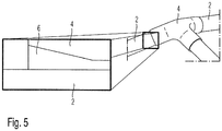
- Fig. 5 shows an arrangement of a positioning element 4, an adhesive 6 and a rod 2 in conjunction with a longitudinal section along a longitudinal direction of the rod 2 according to one embodiment.
- an end portion of the positioning member 4 formed as a half-shell adjoining an exposed portion of the rod 2 may be formed such that a distance between the surface of the positioning member 4 facing the rod 2 and the rod 2 toward the other end of the positioning member 4 decreases steadily to a substantially constant value.
- the distance between the rod 2 facing surface of the positioning element 4 and the rod 2 in the direction of the other end of the positioning element 4 by one or more gradations decrease to a substantially constant value.
- the adhesive 6 may comprise a protruding bead projecting beyond the end of the positioning element 4 for further removal of peak voltages.
- the application of the fiber windings is preferably carried out using a winding machine developed by the wbk Institut für philosophicalstechnik of the Düsseldorf Institute of Technology, which allows the filament windings to be laid down with stationary rods and stationary positioning element (s), ie the individual workpieces are not about one axis have to be turned.
- a winding machine developed by the wbk Institut für philosophicalstechnik of the Düsseldorf Institute of Technology, which allows the filament windings to be laid down with stationary rods and stationary positioning element (s), ie the individual workpieces are not about one axis have to be turned.
- the rods can be advantageously connected in an automated series process.
Landscapes
- Engineering & Computer Science (AREA)
- Chemical & Material Sciences (AREA)
- Mechanical Engineering (AREA)
- Combustion & Propulsion (AREA)
- Transportation (AREA)
- Architecture (AREA)
- Structural Engineering (AREA)
- Composite Materials (AREA)
- Manufacturing & Machinery (AREA)
- Moulding By Coating Moulds (AREA)
Claims (24)
- Construction porteuse (1) en treillis comprenant :une première barre et une seconde barre (2) d'un support d'essieu d'un véhicule,un élément de positionnement (4),caractérisée en ce qu'elle comprend en outre :un premier et un second enroulements de fibres (5), l'élément de positionnement (4) fixant l'orientation de la première barre par rapport à l'orientation de la seconde barre, etun premier segment d'appui de l'élément de positionnement (4) étant tiré par le premier enroulement de fibres en direction d'un segment d'appui de la première barre, et un second segment d'appui de l'élément de positionnement étant tiré par le second enroulement de fibres dans la direction d'un segment d'appui de la seconde barre de façon à maintenir par une liaison par friction, la première barre et la seconde barre dans l'orientation relative fixée l'une par rapport à l'autre.
- Construction porteuse conforme à la revendication 1,
dans laquelle le premier et le second segments d'appui de l'élément de positionnement (4) comportent un dispositif de guidage respectif par l'intermédiaire duquel le premier et le second enroulements de fibres (4) sont respectivement guidés. - Construction porteuse conforme à l'une des revendications précédentes,
dans laquelle le premier segment d'appui de l'élément de positionnement est en outre fixé par une liaison par la matière sur le segment d'appui de la première barre et le second segment d'appui de l'élément de positionnement est fixé en outre par une liaison par la matière sur le segment d'appui de la seconde barre. - Construction porteuse conforme à la revendication 3,
dans laquelle la liaison par la matière s'effectue au moyen d'une colle (6) respectivement prévue entre le premier segment d'appui de l'élément de positionnement et le segment d'appui de la première barre et le second segment d'appui de l'élément de positionnement et le segment d'appui de la seconde barre. - Construction porteuse conforme à la revendication 4,
dans laquelle la distance d'un segment d'extrémité de l'élément de positionnement (4) se connectant à un segment libre de la première barre (2) en direction d'un autre segment d'extrémité de l'élément de positionnement (4) diminue de manière continue ou par paliers jusqu'à une valeur essentiellement constante. - Construction porteuse conforme à la revendication 4 ou 5,
dans laquelle à la suite du segment d'extrémité de l'élément de positionnement (4) est formé un bourrelet en saillie constitué de colle. - Construction porteuse conforme à l'une des revendications précédentes,
dans laquelle l'élément de positionnement (4) comprend une demi-coque (4-1, 4-2) dont la surface tournée vers le segment d'appui de la première barre (2) s'applique par une liaison par la forme sur le segment d'appui de la seconde barre (2). - Construction porteuse conforme à l'une des revendications 1 à 6,
dans laquelle l'élément de positionnement (4) est réalisé sous la forme d'un collier de serrage, et le premier segment d'appui et le second segment d'appui de l'élément de positionnement (4) sont reliés par un segment cintré. - Construction porteuse conforme à l'une des revendications précédentes,
dans laquelle les enroulements de fibres (5) renferment au moins une fibre choisie dans le groupe constitué par une fibre de carbone, une fibre de verre, une fibre d'aramide et une fibre naturelle. - Construction porteuse conforme à la revendication 9,
dans laquelle la fibre est enrobée dans un matériau formant matrice choisi parmi un matériau formant matrice thermoplastique et un matériau formant matrice thermodurcissable. - Construction porteuse conforme à l'une des revendications précédente,
dans laquelle la première barre (2) et/ou la seconde barre (2) renferment) un matériau synthétique renforcé par des fibres ou un métal. - Construction porteuse conforme à l'une des revendications précédente,
dans laquelle l'élément de positionnement (4) est réalisé en un matériau synthétique, en un matériau synthétique renforcé par des fibres ou en un métal. - Procédé d'obtention d'une construction porteuse (1) en treillis comprenant des étapes consistant à :mettre en place un premier segment d'appui d'un élément de positionnement (4) sur un segment d'appui d'une première barre (2) d'un support d'essieu d'un véhicule automobile,mettre en place un second segment d'appui de l'élément de positionnement (4) sur un segment d'appui d'une seconde barre (2) d'un support d'essieu d'un véhicule automobile,relier le premier segment d'appui de l'élément de positionnement au segment d'appui de la première barre (2) par un enroulement de fibres (5) qui tire le premier segment d'appui de l'élément de positionnement (4) en direction du segment d'appui de la première barre (2), et relier le second segment d'appui de l'élément de positionnement au segment d'appui de la seconde barre (2) par un autre enroulement de fibres (5) qui tire le second segment d'appui de l'élément de positionnement (4) en direction du segment d'appui de la seconde barre (2) de façon à maintenir la première barre et la seconde barre (2) dans une orientation relative fixée l'une par rapport à l'autre par liaison par friction.
- Procédé conforme à la revendication 13, selon lequel le premier et le second segments d'appui de l'élément de positionnement (4) comportent un dispositif de guidage respectif, et des segments du premier et du second enroulements (4) sont respectivement insérés dans le dispositif de guidage correspondant.
- Procédé conforme à l'une des revendications 13 et 14, selon lequel le premier segment d'appui de l'élément de positionnement est en outre fixé par une liaison par la matière sur le segment d'appui de la première barre et le second segment d'appui de l'élément de positionnement est en outre fixé par une liaison par la matière sur le segment d'appui de la seconde barre.
- Procédé conforme à la revendication 15, selon lequel, pour obtenir les liaisons par la matière, des adhésifs (6) sont respectivement prévus entre le premier segment d'appui de l'élément de positionnement et le segment d'appui de la première barre et entre le second segment d'appui de l'élément de positionnement et le segment d'appui de la seconde barre.
- Procédé conforme à la revendication 16, selon lequel, la distance d'un segment d'extrémité de l'élément de positionnement (4) se connectant à un segment libre de la première barre (2) en direction d'un autre segment d'extrémité de l'élément de positionnement (4) diminue de manière continue ou par paliers jusqu'à une valeur essentiellement constante.
- Procédé conforme à la revendication 16 ou 17, selon lequel, à la suite du segment d'extrémité de l'élément de positionnement (4) est formé un bourrelet en saillie réalisé en colle.
- Procédé conforme à l'une des revendications 13 à 18, selon lequel l'élément de positionnement (4) est réalisé sous la forme d'une demi-coque (4-1, 4-2) dont la surface tournée vers le segment d'appui de la première barre (2) s'applique sur le segment d'appui de la première barre (2) par une liaison par la forme.
- Procédé conforme à l'une des revendications 13 à 18, selon lequel l'élément de positionnement (4) est réalisé sous la forme d'un collier de serrage et le premier segment d'appui et le second segment d'appui de l'élément de positionnement (4) sont reliés par un segment cintré.
- Procédé conforme à l'une des revendications 13 à 20, selon lequel les enroulements de fibres (5) renferment au moins une fibre choisie parmi une fibre de carbone, une fibre de verre, une fibre d'aramide et une fibre naturelle.
- Procédé conforme à la revendication 21, selon lequel la fibre est enrobée dans un matériau formant matrice choisi parmi un matériau formant matrice thermoplastique et un matériau formant matrice thermodurcissable.
- Procédé conforme à l'une des revendications 13 à 22, selon lequel la première barre (2) et/ou la première barre (2) renferme(nt) un matériau synthétique renforcé par des fibres ou un métal.
- Procédé conforme à l'une des revendications 13 à 23, selon lequel l'élément de positionnement (4) est réalisé en un matériau synthétique, en un matériau synthétique renforcé par des fibres, ou en un métal.
Applications Claiming Priority (2)
| Application Number | Priority Date | Filing Date | Title |
|---|---|---|---|
| DE102013225909.3A DE102013225909A1 (de) | 2013-12-13 | 2013-12-13 | Trägerkonstruktion in Fachwerkbauweise und Verfahren zu deren Herstellung |
| PCT/EP2014/076255 WO2015086378A1 (fr) | 2013-12-13 | 2014-12-02 | Construction porteuse en treillis et son procédé de fabrication |
Publications (2)
| Publication Number | Publication Date |
|---|---|
| EP3079975A1 EP3079975A1 (fr) | 2016-10-19 |
| EP3079975B1 true EP3079975B1 (fr) | 2018-02-28 |
Family
ID=52007012
Family Applications (1)
| Application Number | Title | Priority Date | Filing Date |
|---|---|---|---|
| EP14806612.9A Active EP3079975B1 (fr) | 2013-12-13 | 2014-12-02 | Construction porteuse en treillis et son procédé de fabrication |
Country Status (5)
| Country | Link |
|---|---|
| US (1) | US9845116B2 (fr) |
| EP (1) | EP3079975B1 (fr) |
| CN (1) | CN105612100B (fr) |
| DE (1) | DE102013225909A1 (fr) |
| WO (1) | WO2015086378A1 (fr) |
Families Citing this family (8)
| Publication number | Priority date | Publication date | Assignee | Title |
|---|---|---|---|---|
| DE102014104638A1 (de) * | 2014-04-02 | 2015-10-08 | Dr. Ing. H.C. F. Porsche Aktiengesellschaft | Verfahren zum Verbinden von Hohlprofilen |
| DE102015014358A1 (de) * | 2015-11-06 | 2017-05-11 | Audi Ag | Verfahren zur Herstellung einer Knotenstruktur mit wenigstens zwei Profilbauteilen, sowie Knotenstruktur und Karosserie |
| CN108263497A (zh) * | 2016-12-31 | 2018-07-10 | 郑州吉田专利运营有限公司 | 碳纤维织物复合材料整车骨架及其制备方法 |
| CN108263494A (zh) * | 2016-12-31 | 2018-07-10 | 郑州吉田专利运营有限公司 | 包卷的碳纤维缠绕结构件及其制备的立体框架和应用 |
| CN108263481A (zh) * | 2016-12-31 | 2018-07-10 | 郑州吉田专利运营有限公司 | 包卷的碳纤维编织结构件及其制备的立体框架和应用 |
| US11306751B2 (en) * | 2017-08-31 | 2022-04-19 | Divergent Technologies, Inc. | Apparatus and methods for connecting tubes in transport structures |
| CN111827471A (zh) * | 2020-08-07 | 2020-10-27 | 中国民航大学 | 一种适用于桁架间对中连接的装配式节点 |
| DE102024119778A1 (de) * | 2024-07-11 | 2026-01-15 | Bayerische Motoren Werke Aktiengesellschaft | Modulares Stecksystem zum Aufbau einer Tragstruktur, Verfahren zur Herstellung einer Tragstruktur sowie Handhabungsvorrichtung |
Family Cites Families (8)
| Publication number | Priority date | Publication date | Assignee | Title |
|---|---|---|---|---|
| DE1936903B2 (de) * | 1969-07-19 | 1972-04-06 | Rudolf, Artur, 5221 Hermesdorf | Verbindung von laenglichen bauteilen fuer geruest- und skelettkonstruktionen o dgl |
| DE4423642C1 (de) * | 1994-07-06 | 1995-10-12 | Daimler Benz Aerospace Ag | Tragrahmen, insbesondere für ein Kraftfahrzeug |
| DE19724535C1 (de) * | 1997-06-11 | 1998-07-09 | Deutsch Zentr Luft & Raumfahrt | Verbindungselement für Mehrkant-, insbesondere Dreikant-Fachwerkträger |
| DE102009019468A1 (de) * | 2009-05-04 | 2010-11-25 | Waldemar Rothe | Verbindungselement für Rohre, Verfahren zum Verbinden von Rohren und Verwendung des Verbindungselementes |
| EP2360082B1 (fr) * | 2010-02-22 | 2013-09-11 | Ria Kaiser | Support longitudinal pour un châssis et son procédé de fabrication |
| DE102010054935B4 (de) | 2010-12-17 | 2013-11-28 | Daimler Ag | Karosseriemodulbauteil |
| DE102011100334A1 (de) * | 2011-05-04 | 2012-11-08 | Sebastian Jansen | Verbindungsanordnung für Bambusrohre |
| EP2511084B1 (fr) * | 2011-04-14 | 2014-11-12 | Magna Steyr Fahrzeugtechnik AG & Co KG | Elément de noeud en matière plastique renforcée de fibres et procédé de fabrication et d'utilisation associé |
-
2013
- 2013-12-13 DE DE102013225909.3A patent/DE102013225909A1/de not_active Withdrawn
-
2014
- 2014-12-02 WO PCT/EP2014/076255 patent/WO2015086378A1/fr not_active Ceased
- 2014-12-02 CN CN201480055836.XA patent/CN105612100B/zh active Active
- 2014-12-02 EP EP14806612.9A patent/EP3079975B1/fr active Active
-
2016
- 2016-06-10 US US15/178,687 patent/US9845116B2/en active Active
Also Published As
| Publication number | Publication date |
|---|---|
| WO2015086378A1 (fr) | 2015-06-18 |
| US20160280285A1 (en) | 2016-09-29 |
| US9845116B2 (en) | 2017-12-19 |
| DE102013225909A1 (de) | 2015-06-18 |
| CN105612100A (zh) | 2016-05-25 |
| CN105612100B (zh) | 2017-11-21 |
| EP3079975A1 (fr) | 2016-10-19 |
Similar Documents
| Publication | Publication Date | Title |
|---|---|---|
| EP3079975B1 (fr) | Construction porteuse en treillis et son procédé de fabrication | |
| EP2242682B1 (fr) | Procédé pour relier deux sections de fuselage par la création d'un joint transversal ainsi que d'une liaison de joint transversal | |
| DE102006022279B4 (de) | Rotorblatt für eine Windenergieanlage | |
| DE102016221309A1 (de) | Halterungsstruktur für ein Kraftübertragungselement, Flugzeugreaktionsverbindung, Flugsteuerflächenantriebseinheit, Verfahren zur Befestigung eines Kraftübertragungselements und Verfahren zur Herstellung einer Flugzeugreaktionsverbindung | |
| DE102009047671A1 (de) | Verfahren zum Anbinden eines Faserverbundbauteils an ein Strukturbauteil eines Luft- und Raumfahrzeuges und eine entsprechende Anordnung | |
| EP3079927B1 (fr) | Ensemble composé d'un élément de châssis et d'un élément d'assemblage et procédé pour fixer une élément d'assemblage à un élément de châssis | |
| EP2398636A1 (fr) | Procédé de fabrication d'un corps en forme de coque et corps ainsi obtenu | |
| EP3094868B1 (fr) | Pièce en matière plastique | |
| DE102015219719A1 (de) | Faserverbundbauteil mit integriertem Anbindungssystem | |
| DE102016210123A1 (de) | Versteifungsbauteil für eine Struktur eines Luft- oder Raumfahrzeugs, Luft- oder Raumfahrzeug, sowie Verfahren | |
| DE102013208278A1 (de) | Faserverbundbauteil für ein Fahrzeug | |
| DE202012104559U1 (de) | Faserverbundhybridbauteil | |
| DE102014105973A1 (de) | System aus einer Schwellerverkleidung und einem Befestigungsclip | |
| EP3580052B1 (fr) | Élément de liaison pour relier un élément structural à une structure composite renforcée par fibres | |
| DE102016205916A1 (de) | Drehstabfeder | |
| DE102013225911A1 (de) | Anordnung aus einem ersten Element und einem zweiten Element eines Kraftfahrzeugs sowie Verfahren zum Verbinden eines ersten Elements und eines zweiten Elements eines Kraftfahrzeugs | |
| DE102014001128A1 (de) | Verfahren zum Verbinden eines ersten Bauteils mit einem aus einem faserverstärkten Kunststoff hergestellten zweiten Bauteil | |
| DE102017128496A1 (de) | Verfahren zum Herstellen eines Strukturabschnitts eines Fahrzeugs | |
| EP3781808A1 (fr) | Pale de rotor d'éolienne et éolienne | |
| DE102021003591A1 (de) | Verfahren und Vorrichtung zum Fügen von Profilbauteilen mittels eines Stützfachwerkes aus Faserverbundmaterial | |
| DE102016002759A1 (de) | Verfahren zur Hestellung eines faserverstärkten Bauteils durch Wickeln und Verfahren zum Herstellen eines Zusammenbaus aus solchen faserverstärkten Bauteilen | |
| DE102011100334A1 (de) | Verbindungsanordnung für Bambusrohre | |
| DE102014014474A1 (de) | Befestigungssystem | |
| DE102015105170A1 (de) | Versteifungsstruktur und Verfahren zur Versteifung des Hautfelds eines Flugzeugrumpfs | |
| DE102015112173B4 (de) | Verfahren zur Herstellung eines Anschlussteils für ein rohrförmiges Bauteil aus faserverstärktem Kunststoff |
Legal Events
| Date | Code | Title | Description |
|---|---|---|---|
| PUAI | Public reference made under article 153(3) epc to a published international application that has entered the european phase |
Free format text: ORIGINAL CODE: 0009012 |
|
| 17P | Request for examination filed |
Effective date: 20160504 |
|
| AK | Designated contracting states |
Kind code of ref document: A1 Designated state(s): AL AT BE BG CH CY CZ DE DK EE ES FI FR GB GR HR HU IE IS IT LI LT LU LV MC MK MT NL NO PL PT RO RS SE SI SK SM TR |
|
| AX | Request for extension of the european patent |
Extension state: BA ME |
|
| DAX | Request for extension of the european patent (deleted) | ||
| GRAP | Despatch of communication of intention to grant a patent |
Free format text: ORIGINAL CODE: EPIDOSNIGR1 |
|
| INTG | Intention to grant announced |
Effective date: 20171110 |
|
| GRAS | Grant fee paid |
Free format text: ORIGINAL CODE: EPIDOSNIGR3 |
|
| GRAA | (expected) grant |
Free format text: ORIGINAL CODE: 0009210 |
|
| AK | Designated contracting states |
Kind code of ref document: B1 Designated state(s): AL AT BE BG CH CY CZ DE DK EE ES FI FR GB GR HR HU IE IS IT LI LT LU LV MC MK MT NL NO PL PT RO RS SE SI SK SM TR |
|
| REG | Reference to a national code |
Ref country code: GB Ref legal event code: FG4D Free format text: NOT ENGLISH Ref country code: CH Ref legal event code: EP |
|
| REG | Reference to a national code |
Ref country code: AT Ref legal event code: REF Ref document number: 973787 Country of ref document: AT Kind code of ref document: T Effective date: 20180315 |
|
| REG | Reference to a national code |
Ref country code: IE Ref legal event code: FG4D Free format text: LANGUAGE OF EP DOCUMENT: GERMAN |
|
| REG | Reference to a national code |
Ref country code: DE Ref legal event code: R096 Ref document number: 502014007466 Country of ref document: DE |
|
| REG | Reference to a national code |
Ref country code: NL Ref legal event code: MP Effective date: 20180228 |
|
| REG | Reference to a national code |
Ref country code: LT Ref legal event code: MG4D |
|
| PG25 | Lapsed in a contracting state [announced via postgrant information from national office to epo] |
Ref country code: ES Free format text: LAPSE BECAUSE OF FAILURE TO SUBMIT A TRANSLATION OF THE DESCRIPTION OR TO PAY THE FEE WITHIN THE PRESCRIBED TIME-LIMIT Effective date: 20180228 Ref country code: NO Free format text: LAPSE BECAUSE OF FAILURE TO SUBMIT A TRANSLATION OF THE DESCRIPTION OR TO PAY THE FEE WITHIN THE PRESCRIBED TIME-LIMIT Effective date: 20180528 Ref country code: HR Free format text: LAPSE BECAUSE OF FAILURE TO SUBMIT A TRANSLATION OF THE DESCRIPTION OR TO PAY THE FEE WITHIN THE PRESCRIBED TIME-LIMIT Effective date: 20180228 Ref country code: LT Free format text: LAPSE BECAUSE OF FAILURE TO SUBMIT A TRANSLATION OF THE DESCRIPTION OR TO PAY THE FEE WITHIN THE PRESCRIBED TIME-LIMIT Effective date: 20180228 Ref country code: CY Free format text: LAPSE BECAUSE OF FAILURE TO SUBMIT A TRANSLATION OF THE DESCRIPTION OR TO PAY THE FEE WITHIN THE PRESCRIBED TIME-LIMIT Effective date: 20180228 Ref country code: NL Free format text: LAPSE BECAUSE OF FAILURE TO SUBMIT A TRANSLATION OF THE DESCRIPTION OR TO PAY THE FEE WITHIN THE PRESCRIBED TIME-LIMIT Effective date: 20180228 Ref country code: FI Free format text: LAPSE BECAUSE OF FAILURE TO SUBMIT A TRANSLATION OF THE DESCRIPTION OR TO PAY THE FEE WITHIN THE PRESCRIBED TIME-LIMIT Effective date: 20180228 |
|
| PG25 | Lapsed in a contracting state [announced via postgrant information from national office to epo] |
Ref country code: GR Free format text: LAPSE BECAUSE OF FAILURE TO SUBMIT A TRANSLATION OF THE DESCRIPTION OR TO PAY THE FEE WITHIN THE PRESCRIBED TIME-LIMIT Effective date: 20180529 Ref country code: LV Free format text: LAPSE BECAUSE OF FAILURE TO SUBMIT A TRANSLATION OF THE DESCRIPTION OR TO PAY THE FEE WITHIN THE PRESCRIBED TIME-LIMIT Effective date: 20180228 Ref country code: RS Free format text: LAPSE BECAUSE OF FAILURE TO SUBMIT A TRANSLATION OF THE DESCRIPTION OR TO PAY THE FEE WITHIN THE PRESCRIBED TIME-LIMIT Effective date: 20180228 Ref country code: SE Free format text: LAPSE BECAUSE OF FAILURE TO SUBMIT A TRANSLATION OF THE DESCRIPTION OR TO PAY THE FEE WITHIN THE PRESCRIBED TIME-LIMIT Effective date: 20180228 Ref country code: BG Free format text: LAPSE BECAUSE OF FAILURE TO SUBMIT A TRANSLATION OF THE DESCRIPTION OR TO PAY THE FEE WITHIN THE PRESCRIBED TIME-LIMIT Effective date: 20180528 |
|
| PG25 | Lapsed in a contracting state [announced via postgrant information from national office to epo] |
Ref country code: MT Free format text: LAPSE BECAUSE OF FAILURE TO SUBMIT A TRANSLATION OF THE DESCRIPTION OR TO PAY THE FEE WITHIN THE PRESCRIBED TIME-LIMIT Effective date: 20180228 |
|
| PG25 | Lapsed in a contracting state [announced via postgrant information from national office to epo] |
Ref country code: PL Free format text: LAPSE BECAUSE OF FAILURE TO SUBMIT A TRANSLATION OF THE DESCRIPTION OR TO PAY THE FEE WITHIN THE PRESCRIBED TIME-LIMIT Effective date: 20180228 Ref country code: EE Free format text: LAPSE BECAUSE OF FAILURE TO SUBMIT A TRANSLATION OF THE DESCRIPTION OR TO PAY THE FEE WITHIN THE PRESCRIBED TIME-LIMIT Effective date: 20180228 Ref country code: AL Free format text: LAPSE BECAUSE OF FAILURE TO SUBMIT A TRANSLATION OF THE DESCRIPTION OR TO PAY THE FEE WITHIN THE PRESCRIBED TIME-LIMIT Effective date: 20180228 Ref country code: RO Free format text: LAPSE BECAUSE OF FAILURE TO SUBMIT A TRANSLATION OF THE DESCRIPTION OR TO PAY THE FEE WITHIN THE PRESCRIBED TIME-LIMIT Effective date: 20180228 |
|
| REG | Reference to a national code |
Ref country code: DE Ref legal event code: R097 Ref document number: 502014007466 Country of ref document: DE |
|
| PG25 | Lapsed in a contracting state [announced via postgrant information from national office to epo] |
Ref country code: CZ Free format text: LAPSE BECAUSE OF FAILURE TO SUBMIT A TRANSLATION OF THE DESCRIPTION OR TO PAY THE FEE WITHIN THE PRESCRIBED TIME-LIMIT Effective date: 20180228 Ref country code: SK Free format text: LAPSE BECAUSE OF FAILURE TO SUBMIT A TRANSLATION OF THE DESCRIPTION OR TO PAY THE FEE WITHIN THE PRESCRIBED TIME-LIMIT Effective date: 20180228 Ref country code: SM Free format text: LAPSE BECAUSE OF FAILURE TO SUBMIT A TRANSLATION OF THE DESCRIPTION OR TO PAY THE FEE WITHIN THE PRESCRIBED TIME-LIMIT Effective date: 20180228 Ref country code: DK Free format text: LAPSE BECAUSE OF FAILURE TO SUBMIT A TRANSLATION OF THE DESCRIPTION OR TO PAY THE FEE WITHIN THE PRESCRIBED TIME-LIMIT Effective date: 20180228 |
|
| PLBE | No opposition filed within time limit |
Free format text: ORIGINAL CODE: 0009261 |
|
| STAA | Information on the status of an ep patent application or granted ep patent |
Free format text: STATUS: NO OPPOSITION FILED WITHIN TIME LIMIT |
|
| 26N | No opposition filed |
Effective date: 20181129 |
|
| PG25 | Lapsed in a contracting state [announced via postgrant information from national office to epo] |
Ref country code: SI Free format text: LAPSE BECAUSE OF FAILURE TO SUBMIT A TRANSLATION OF THE DESCRIPTION OR TO PAY THE FEE WITHIN THE PRESCRIBED TIME-LIMIT Effective date: 20180228 |
|
| REG | Reference to a national code |
Ref country code: CH Ref legal event code: PL |
|
| PG25 | Lapsed in a contracting state [announced via postgrant information from national office to epo] |
Ref country code: LU Free format text: LAPSE BECAUSE OF NON-PAYMENT OF DUE FEES Effective date: 20181202 Ref country code: MC Free format text: LAPSE BECAUSE OF FAILURE TO SUBMIT A TRANSLATION OF THE DESCRIPTION OR TO PAY THE FEE WITHIN THE PRESCRIBED TIME-LIMIT Effective date: 20180228 |
|
| REG | Reference to a national code |
Ref country code: IE Ref legal event code: MM4A |
|
| REG | Reference to a national code |
Ref country code: BE Ref legal event code: MM Effective date: 20181231 |
|
| PG25 | Lapsed in a contracting state [announced via postgrant information from national office to epo] |
Ref country code: IE Free format text: LAPSE BECAUSE OF NON-PAYMENT OF DUE FEES Effective date: 20181202 |
|
| PG25 | Lapsed in a contracting state [announced via postgrant information from national office to epo] |
Ref country code: BE Free format text: LAPSE BECAUSE OF NON-PAYMENT OF DUE FEES Effective date: 20181231 |
|
| PG25 | Lapsed in a contracting state [announced via postgrant information from national office to epo] |
Ref country code: LI Free format text: LAPSE BECAUSE OF NON-PAYMENT OF DUE FEES Effective date: 20181231 Ref country code: CH Free format text: LAPSE BECAUSE OF NON-PAYMENT OF DUE FEES Effective date: 20181231 |
|
| PG25 | Lapsed in a contracting state [announced via postgrant information from national office to epo] |
Ref country code: TR Free format text: LAPSE BECAUSE OF FAILURE TO SUBMIT A TRANSLATION OF THE DESCRIPTION OR TO PAY THE FEE WITHIN THE PRESCRIBED TIME-LIMIT Effective date: 20180228 |
|
| PG25 | Lapsed in a contracting state [announced via postgrant information from national office to epo] |
Ref country code: PT Free format text: LAPSE BECAUSE OF FAILURE TO SUBMIT A TRANSLATION OF THE DESCRIPTION OR TO PAY THE FEE WITHIN THE PRESCRIBED TIME-LIMIT Effective date: 20180228 |
|
| PG25 | Lapsed in a contracting state [announced via postgrant information from national office to epo] |
Ref country code: MK Free format text: LAPSE BECAUSE OF NON-PAYMENT OF DUE FEES Effective date: 20180228 Ref country code: HU Free format text: LAPSE BECAUSE OF FAILURE TO SUBMIT A TRANSLATION OF THE DESCRIPTION OR TO PAY THE FEE WITHIN THE PRESCRIBED TIME-LIMIT; INVALID AB INITIO Effective date: 20141202 |
|
| PG25 | Lapsed in a contracting state [announced via postgrant information from national office to epo] |
Ref country code: IS Free format text: LAPSE BECAUSE OF FAILURE TO SUBMIT A TRANSLATION OF THE DESCRIPTION OR TO PAY THE FEE WITHIN THE PRESCRIBED TIME-LIMIT Effective date: 20180628 |
|
| REG | Reference to a national code |
Ref country code: AT Ref legal event code: MM01 Ref document number: 973787 Country of ref document: AT Kind code of ref document: T Effective date: 20191202 |
|
| PG25 | Lapsed in a contracting state [announced via postgrant information from national office to epo] |
Ref country code: AT Free format text: LAPSE BECAUSE OF NON-PAYMENT OF DUE FEES Effective date: 20191202 |
|
| P01 | Opt-out of the competence of the unified patent court (upc) registered |
Effective date: 20230502 |
|
| PGFP | Annual fee paid to national office [announced via postgrant information from national office to epo] |
Ref country code: DE Payment date: 20251203 Year of fee payment: 12 |
|
| PGFP | Annual fee paid to national office [announced via postgrant information from national office to epo] |
Ref country code: GB Payment date: 20251218 Year of fee payment: 12 |
|
| PGFP | Annual fee paid to national office [announced via postgrant information from national office to epo] |
Ref country code: FR Payment date: 20251217 Year of fee payment: 12 |
|
| PGFP | Annual fee paid to national office [announced via postgrant information from national office to epo] |
Ref country code: IT Payment date: 20251231 Year of fee payment: 12 |