EP3080034B1 - Bremskraftüberwachung einer aufzugsbremse - Google Patents
Bremskraftüberwachung einer aufzugsbremse Download PDFInfo
- Publication number
- EP3080034B1 EP3080034B1 EP14809030.1A EP14809030A EP3080034B1 EP 3080034 B1 EP3080034 B1 EP 3080034B1 EP 14809030 A EP14809030 A EP 14809030A EP 3080034 B1 EP3080034 B1 EP 3080034B1
- Authority
- EP
- European Patent Office
- Prior art keywords
- brake
- force
- closed
- spring
- open
- Prior art date
- Legal status (The legal status is an assumption and is not a legal conclusion. Google has not performed a legal analysis and makes no representation as to the accuracy of the status listed.)
- Active
Links
Images




Classifications
-
- B—PERFORMING OPERATIONS; TRANSPORTING
- B66—HOISTING; LIFTING; HAULING
- B66B—ELEVATORS; ESCALATORS OR MOVING WALKWAYS
- B66B5/00—Applications of checking, fault-correcting, or safety devices in elevators
- B66B5/0006—Monitoring devices or performance analysers
- B66B5/0018—Devices monitoring the operating condition of the elevator system
- B66B5/0031—Devices monitoring the operating condition of the elevator system for safety reasons
-
- B—PERFORMING OPERATIONS; TRANSPORTING
- B66—HOISTING; LIFTING; HAULING
- B66B—ELEVATORS; ESCALATORS OR MOVING WALKWAYS
- B66B1/00—Control systems of elevators in general
- B66B1/34—Details, e.g. call counting devices, data transmission from car to control system, devices giving information to the control system
-
- B—PERFORMING OPERATIONS; TRANSPORTING
- B66—HOISTING; LIFTING; HAULING
- B66D—CAPSTANS; WINCHES; TACKLES, e.g. PULLEY BLOCKS; HOISTS
- B66D5/00—Braking or detent devices characterised by application to lifting or hoisting gear, e.g. for controlling the lowering of loads
- B66D5/02—Crane, lift hoist, or winch brakes operating on drums, barrels, or ropes
- B66D5/06—Crane, lift hoist, or winch brakes operating on drums, barrels, or ropes with radial effect
- B66D5/08—Crane, lift hoist, or winch brakes operating on drums, barrels, or ropes with radial effect embodying blocks or shoes
-
- B—PERFORMING OPERATIONS; TRANSPORTING
- B66—HOISTING; LIFTING; HAULING
- B66D—CAPSTANS; WINCHES; TACKLES, e.g. PULLEY BLOCKS; HOISTS
- B66D5/00—Braking or detent devices characterised by application to lifting or hoisting gear, e.g. for controlling the lowering of loads
- B66D5/02—Crane, lift hoist, or winch brakes operating on drums, barrels, or ropes
- B66D5/24—Operating devices
- B66D5/30—Operating devices electrical
Definitions
- the present disclosure relates to elevators and particularly to a method and apparatus for monitoring spring force within a brake system mounted in conjunction with an elevator motor.
- the apparatus can be provided preassembled together with the brake system and motor as a drive for newly planned installations, it is envisaged that the apparatus is particularly beneficial when supplied as a kit for modernising existing installations.
- a brake is normally provided to halt rotation of the motor in traction elevators.
- the brake includes a brake drum either mounted directly on an output shaft of the motor or, alternatively, indirectly connected thereto via a gear.
- At least one pivotal brake arm having a brake lining is biased by a compressed spring towards the drum so that when the brake closes the lining frictionally engages with a brake surface on the drum to halt the motor.
- An actuator typically electromagnetically, hydraulically or pneumatically driven, is provided to act on the brake arm to open the brake by further compressing the spring to overcome the spring bias and move the arm and lining away from the drum. Consequently, in the open brake position, the spring force acting on the brake arm is greater than in the closed brake position.
- one or more brake contacts monitor the position of the brake arm to determine whether the brake is open or closed so as to prevent the motor from starting when the brake is closed.
- a further system is outlined in WO-A1-2011/098850 which again uses load cells but not to determine whether the brake is open or closed as in JPH-A-0672672, but instead to measure the actual spring force when the brake is closed to detect whether the brake lining is worn out.
- the brake lining is a sacrificial component of the brake which gradually erodes and as the lining erodes, the spring force when the brake is closed decreases. Accordingly, if the actual spring force monitored by the load cells during braking (closed brake) is not within predefined force limits or boundaries a signal is output to the elevator controller which can be subsequently used to take the effected elevator out of operation and/or inform a remote monitoring centre that the brake needs service.
- the elevator drive whether installed within an elevator hoistway or in its own dedicated machine room located above, beside or below the hoistway, can be exposed to dramatic temperature variations throughout the course of a year.
- the brake drum is particularly susceptible to these variations.
- a conservative estimate is that a temperature increase of 50°C, which results in expansion of the drum, will reduce the air gap between the brake lining and the drum with the brake in its open position by around 30%.
- the brake although being detected as being open with the system outlined in JPH-A-0672672, might actually be closed. This gives rise to a condition known as dragging where the elevator travels with a closed brake.
- There are obvious disadvantages to dragging most notably excessive wear of the braking components particularly the brake linings substantial increase in mechanical and electrical stress imposed upon the motor and a drastic reduction in overall energy efficiency.
- WO-A1-2011/098850 only monitors the actual spring force with the brake in the closed position so as to detect when the lining has worn out. Accordingly, the system will eventually detect dragging but only after the lining has worn out which, as mentioned above, is a direct result of the continuous elevator dragging.
- EP 2 522 874 A discloses a method for monitoring an elevator drive brake comprising detecting a spring force when the brake is closed.
- EP 2 522 874 A also discloses a brake force monitor for an elevator drive brake comprising:a force sensor for each brake spring to be monitored, and an electronic monitor.
- the invention provides a method and apparatus for monitoring an elevator drive brake.
- the method comprises the steps of detecting a spring force when the brake is closed, detecting a spring force when the brake is open, determining the difference between the two detected spring forces, and comparing the difference between the two detected spring forces with at least one preset permissible force differential to determine whether the brake is defective.
- the apparatus comprises a force sensor for each brake spring to be monitored, and an electronic monitor that stores at least one preset permissible force differential and, during operation, compares the at least one preset permissible force differential with an actual force difference between an open spring force and a closed spring force as detected by the force sensor.
- the preset permissible force differential can be a minimum force differential such that the brake is determined to be defective if the difference between the two detected spring forces is less than or equal to the minimum force differential.
- the preset permissible force differential can be a maximum force differential such that the brake is determined to be defective if the difference between the two detected spring forces is greater than or equal to maximum force differential. This is an effective way of determining that the brake lining has worn excessively.
- an elevator safety chain is opened if the brake is defective.
- the safety chain may be opened immediately if the elevator is not travelling or, alternatively, only after the elevator has completed its current travel so as to allow any passengers travelling in the elevator to disembark.
- the detected spring force can be stored.
- the spring force is continuously detected while the brake is closed or open and the last value detected is stored as the detected spring force. This procedure further helps to mitigate the effects of sensor drift.
- the difference between the open and closed spring forces can be stored and subsequently accessed by or displayed to a maintenance technician to enable him to gauge the nature of the brake defect. If the difference is less than or equal to the minimum force differential, the technician can check for brake dragging, broken brake springs or problems associated with the actuator. If the difference is greater than or equal to the maximum force differential, this will indicate to the technician that the brake lining has worn excessively.
- Preferably commissioning is achieved by adjusting the brake, closing the brake, detecting and storing a closed spring force, opening the brake, recording and storing an open spring force, determining the difference between the open spring force and the closed spring force, and calculating and storing at least one preset permissible force differential from the determined difference between the open spring force and the closed spring force.
- the preset permissible force differential can be a minimum force differential which is calculated by multiplying the difference between the open spring force and the closed spring force by a factor of less than one, preferably less than 0.75.
- the preset permissible force differential can be a maximum force differential which is calculated by multiplying the difference between the open spring force and the closed spring force by a factor greater than one but preferably less than 1.1.
- the system may be self-checking so that it can automatically determine whether power is available and whether force sensors are functioning. If either of these two determinations are negative, the elevator safety circuit can be opened and the elevator taken out of operation. Furthermore determinations can be made as to whether a voltage sensor is functioning and whether elevator is in travel such that the elevator safety circuit is opened if both determinations are negative.
- the apparatus can be supplied as a kit for modernising existing elevator installations or for subassembly in the factory with the drive for a new installation.
- the apparatus may include a sensor to detect energisation of the brake actuator and thereby determine whether the brake is open or closed.
- the apparatus can be interconnected to an elevator safety chain to interrupt the safety chain if a brake defect is detected. It can be interconnected directly to the safety chain or, alternatively, indirectly connected via an elevator controller.
- the invention also provided an elevator installation including the brake force monitoring apparatus, a motor, and a brake with at least one spring biasing the brake into its closed position.
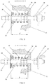
- FIGS. 1 and 2 are schematic plan views of the same elevator brake 1. Whereas FIG. 1 depicts the brake 1 in its closed position, FIG. 2 shows the brake 1 in its open position.
- the brake 1 includes a brake drum 6 either mounted directly on a shaft 4 either directly connected to a motor or, alternatively, indirectly connected thereto via a gear.
- Two brake arms 10 are provided at opposing sides of the drum 6 and are mounted at their lower ends on pivots 14 connected to a housing 2 of either the motor or the gear.
- Each arm 10 is fitted with a brake lining 12 and is biased by a pre-tensioned compression spring 16 towards the drum 6.
- the forces imposed on the brake arms 10 by the springs 16 are illustrated by the arrows F s1 and F s2 , respectively.
- An electromagnetic actuator 20 is provided between and interconnects the upper ends of the brake arms 10.
- the actuator 20 includes a housing 26 containing a series of solenoid coils 22 and a movable solenoid plunger 24 extending from the housing 26
- the electromagnetic actuator 20 is de-energised and therefore unable to resist the inward biasing forces F s1 and F s2 of the brake springs 16 on the arms 10. Accordingly, the brake linings 12 frictionally engage with a brake surface on the drum 6 to either halt rotation of the shaft 4 or retain the shaft 4 in a stationary position.
- FIG. 3 A cross section of the left brake spring 16, as indicated by the reference numeral A in FIG. 1 , is illustrated in FIG. 3 .
- a threaded rod 30 is secured at one end by a lock nut 34 to a bracket 32 mounted to the motor or gear housing 2 (as shown in FIGS. 1 and 2 ).
- the rod 30 extends from the bracket 32 through a hole provided in the brake arm 10.
- the pre-tensioned compression spring 16 is mounted over the threaded rod 30 between the brake arm 10 and spring endplate or retainer 18.
- An adjustment nut 36 and associated lock nut 34 are screwed onto the end of the rod 30 for engagement with the spring retainer 18. Accordingly, the position of the spring retainer 18 along the rod 30, and thereby the compression E of the spring 16, can be modified or fine-tuned by careful adjustment of the adjustment nut 36 and associated lock nut 34 along the threaded rod 30.
- the brake arm 10 When the brake 1 is opened by the electromagnetic actuator 20, the brake arm 10 is moved under the influence of the electromagnet opening force F e1 in the opening direction O to further compress the spring 16.
- the extent to which the arm 10 can move in the opening direction O is limited by a washer and associated stop nut 38 provided on the rod 30.
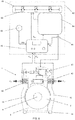
- FIG. 4 The main components of a brake force monitoring kit 40 according to the invention are shown in FIG. 4 .
- a force sensor 42 for each brake spring 16 to be monitored is provided with the kit 40.
- two such force sensors 42 are included to monitor the two opposing springs 16 of the brake 1 illustrated in FIGS. 1 to 3 .
- Each force sensor 42 is disc shaped, may incorporate the functionality of the spring retainer or endplate 18 and may incorporate a strain gauge or may comprise a load cell as previously discussed with reference to the prior art.
- a sensor 44 is provided to detect whether the electromagnetic actuator 20 is being supplied with electrical power from the elevator controller 64.
- the sensor 44 is a voltage sensor.
- each electromagnetic actuator 20 used for elevator brakes 1 has specific characteristics and in particular a unique electrical profile. For example, as the voltage supplied to the actuator 20 increases, there will be a specific minimum opening voltage U o at which the brake 1 opens fully. Conversely, as the voltage is withdrawn from the actuator 20, there will be a maximum closing voltage U c at which the brake 1 closes. By comparing the actual voltage signal U s with the preset maximum closing voltage U c , it is possible to determine whether the brake 1 is closed or open.
- the kit 40 includes an electronic monitor 46 comprising a housing or enclosure 56 protecting a processor 48 and electronic storage 50 mounted on an internal printed circuit board.
- the monitor 46 includes a manual push-button 52, an optional display 54, two LEDs L1 and L2, and multiple signal inputs and outputs (not shown).
- the first stage in installing the brake force monitoring kit 40 is to mount each of the force sensors 42 between the spring retainer 18 and the associated adjustment nut 36 as illustrated in FIG. 5 . It will be appreciated that instead of using separate force sensors 42, the force sensors can be integrated into new spring retainers 18.
- the electronic monitor 46 is mounted within an elevator control cabinet 60, since the control cabinet 60 normally provides an appropriate power supply 62 as well as access to the elevator safety circuit or chain 66.
- the voltage sensor 44 is positioned to detect whether the electromagnetic actuator 20 is being supplied with electrical power from the elevator controller 64.
- a signal U s from the voltage sensor 44, a power supply PS and signals indicative of the biasing forces F s1 and F s2 of the springs 16 are fed into the monitor 46.
- the monitor 46 can provide a signal S out to stop the elevator by opening a safety contact or relay 68 within the safety chain 66.
- the brake force monitoring kit 40 is being used to modernise an existing elevator brake 1 it is difficult, if not impossible, to easily access or modify the existing controller 64 to accept a signal from the monitor 46. For this reason the output signal S out from the monitor 46 is used to open a safety relay 68 within the safety chain 66 directly.
- the controller 64 in any case, will monitor the safety chain 66 and will take the elevator out of operation if the safety chain 66 is open.
- the monitor 46 can be incorporated within or associated with the new controller 64 and the output signal S out from the monitor 46 can be used by the controller 64 to switch the safety chain 66, as indicated by the dashed lines in FIG. 6 .
- the first step S1 in commissioning is to manually adjust or readjust the brake 1 by means of the adjustment nut 36 in accordance with the brake manufacturer's original instructions.
- the brake 1 is closed in step S2.
- the commissioning engineer presses the push-button 52 on the monitor 46 in step S3 and the monitor 46 then automatically records and stores the closed spring forces F s1 - closed and F s2 - closed obtained from the force sensors 42 for both of the brake springs 16, respectively, in step S4.
- step S5 the electromagnetic actuator 20 is activated or energised to open the brake 1 and in step S6, the final manual step of the commissioning process, the engineer once again presses the push-button 52 and the monitor 46 then automatically records the open spring forces F s1 - open and F s2 . open obtained from the force sensors 42 for both of the brake springs 16, respectively, in step S7. After this the manual commissioning process ends at step S8.
- the monitor calculates and stores in its internal electronic storage 50 values for the minimum permissible force differential ⁇ F 1min and ⁇ F 2min for each of the springs 16, respectively, by applying a multiplier or gain A to each of the actual force differences ⁇ F determined in step S9.
- the gain A is less than one and preferably less than 0.75.
- the monitor 46 will continually compare actual measured force differences ⁇ F 1 and AF 2 with these stored minimum permissible force differentials ⁇ F 1min and ⁇ F 2mm to determine whether there is a brake fault, for example, whether the brake 1 is dragging.
- the monitor 46 can be used to calculate and store values for the maximum permissible force differential ⁇ F 1max and ⁇ F 2max for each of the springs 16, respectively, by applying a multiplier or gain B to each of the actual force differences ⁇ F determined in step S9.
- the gain B is greater than one but preferably less than 1.1.
- the monitor 46 After the process of commissioning has been completed the monitor 46 performs a self-check procedure as illustrated in FIG. 8 .
- the first step S11 of the self-check procedure is a determination as to whether the monitor 46 is being supplied with electricity from the power supply 62. If it is not, the first of the LEDs L1 is unlit, the safety chain 66 shall remain open in step S12 and the process will continuously loop around to the decision in step S11 until the affirmative outcome is achieved. At which point the first LED L1 will be illuminated green and in step S13 the monitor 46 will close the safety chain 66.
- step S14 the monitor 46 will check in step S14 whether the voltage sensor 44 is functioning correctly. This may be achieved by ensuring that a signal U s is being received from the voltage sensor 44. If not, the safety chain 66 is opened in S 15 and the first LED L1 is illuminated orange (indicating a defect with the brake force monitoring kit 40). Otherwise, the process proceeds to step S16.
- step S16 the monitor 46 determines whether the force sensors 42 are functioning accurately. If the force sensors 42 are not functioning, as before, the first LED L1 is illuminated orange and a further determination is made as to whether the elevator is in travel, S17. The brake is open, and thereby the elevator is in travel, if the actual voltage signal U s from the voltage sensor 44 is greater than the preset maximum closing voltage U c .
- step S17 the monitor opens the safety chain 66 immediately in step S18. Otherwise, in step S19 the safety chain 66 is opened only after the elevator has completed its travel. Travel is completed when the brake 1 next closes which is detected when the actual voltage signal U s from the voltage sensor 44 is less than the preset maximum closing voltage U c .
- step S14 If the voltage sensor 44 and the force sensors 42 are functioning, as determined in step S14 and in step S16, the monitor 46 and all of its components are assessed to be functioning correctly, LED L1 will be illuminated green and the self-check procedure ends in step S20.
- FIG. 9 illustrates the overall monitoring process conducted by the brake force monitor 46 including the initial commissioning procedure, step S21, as previously described with reference to FIG. 7 and the subsequent self-check procedure, step S22, outlined in FIG. 8 .
- the monitor 46 compares the signal U s received from the voltage sensor 44 with a preset value U c .
- stage S23 if the actual voltage signal U s is less than the preset maximum closing voltage U c , the monitor 46 deems that the brake 1 is closed. It subsequently detects and stores the values representative of the current closed spring forces F s1-closed and F s2-closed obtained from the force sensors 42 for both of the brake springs 16, respectively, in step S24 and S25. The procedure continuously loops through steps S22, S23, S24 and S25 until the actual voltage signal U s as detected by the voltage sensor 44, is greater than the preset maximum closing voltage U c .
- step S26 values representative of the actual open spring forces F s1-open and F s2-open are obtained from the force sensors 42 for both of the brake springs 16, respectively.
- the monitor 46 concludes that the brake 1 is defective, the second LED L2 is illuminated red (indicating a brake defect), and, in step S28, a value representing the percentage that the actual force difference ⁇ F s is relative to minimum permissible force differential ⁇ F min is stored in storage 50. This value can be subsequently accessed by or displayed to a maintenance technician to enable him to gauge the nature of the brake defect.
- Step S29 the elevator completes its travel and once the monitor 46 judges that the brake 1 has been applied at the end of the travel, as in step S23 when U s ⁇ U c , the monitor 46 can provide a signal S out to take the elevator out of operation by opening a safety relay 68 within the safety chain 66.
- the method and apparatus 40 for monitoring the brake spring force F s can be applied to other brake actuators. Furthermore, the method and apparatus can be used not only to monitor multiple brake springs but also a single brake spring.
Landscapes
- Engineering & Computer Science (AREA)
- Mechanical Engineering (AREA)
- Automation & Control Theory (AREA)
- Computer Networks & Wireless Communication (AREA)
- Maintenance And Inspection Apparatuses For Elevators (AREA)
- Cage And Drive Apparatuses For Elevators (AREA)
Claims (15)
- Verfahren zur Überwachung einer Aufzugsantriebsbremse (1), umfassend die folgenden Schritte:Erfassen einer Federkraft (Fs-geschlossen) bei geschlossener Bremse (S24);Erfassen einer Federkraft (Fs-offen) bei geöffneter Bremse (S26);Bestimmen der Differenz zwischen den zwei erfassten Federkräften (ΔFs); undVergleichen der Differenz zwischen den zwei erfassten Federkräften (ΔFs) mit mindestens einem voreingestellten zulässigen Kraftunterschied (ΔFsmin; ΔFsmax), um zu bestimmen, ob die Bremse defekt ist (S27).
- Verfahren nach Anspruch 1, wobei der voreingestellte zulässige Kraftunterschied ein minimaler Kraftunterschied (AFsmin) ist und die Bremse als fehlerhaft bestimmt wird, wenn die Differenz zwischen den zwei erfassten Federkräften (ΔFs) kleiner oder gleich dem minimalen Kraftunterschied (ΔFsmin) ist.
- Verfahren nach Anspruch 1 oder 2, bei dem der voreingestellte zulässige Kraftunterschied ein maximaler Kraftunterschied (ΔFsmax) ist und die Bremse als fehlerhaft bestimmt wird, wenn die Differenz zwischen den zwei erfassten Federkräften (ΔFs) größer oder gleich dem maximalen Kraftunterschied (ΔFsmax) ist.
- Verfahren nach einem der vorhergehenden Ansprüche, ferner umfassend den Schritt des Öffnens einer Aufzugssicherheitskette (66), wenn die Bremse defekt ist.
- Verfahren nach Anspruch 4, wobei die Sicherheitskette (66) erst geöffnet wird, nachdem der Aufzug seine aktuelle Fahrt beendet hat.
- Verfahren nach einem der vorhergehenden Ansprüche, ferner umfassend den Schritt des Speicherns der erfassten Federkraft (Fs-geschlossen) jedes Mal, wenn die Bremse (S24) geschlossen ist.
- Verfahren nach einem der vorhergehenden Ansprüche, ferner umfassend den Schritt des Erfassens der Erregung eines Bremsaktuators (S23), um zu bestimmen, ob die Bremse offen oder geschlossen ist.
- Verfahren nach Anspruch 7, wobei die dem Bremsaktuator zugeführte Spannung erfasst wird, um zu bestimmen, ob die Bremse offen oder geschlossen ist.
- Verfahren nach einem der vorhergehenden Ansprüche, ferner umfassend den Schritt des Speicherns der Differenz zwischen den beiden erfassten Federkräften (ΔFs), wenn die Bremse defekt ist,
- Verfahren nach einem der vorhergehenden Ansprüche, ferner umfassend einen Inbetriebnahmeschritt (S21), aufweisend:Einstellen der Bremse (S1);Schließen der Bremse (S2);Erfassen und Speichern einer geschlossenen Federkraft (S4);Öffnen der Bremse (S5);Aufzeichnen einer offenen Federkraft (S7);Bestimmen der Differenz (ΔFs) zwischen der offenen Federkraft und der geschlossenen Federkraft (S9); undBerechnen und Speichern des mindestens einen voreingestellten zulässigen Kraftunterschieds (S10) aus der bestimmten Differenz (ΔFs) zwischen der offenen Federkraft und der geschlossenen Federkraft.
- Verfahren nach einem der vorhergehenden Ansprüche, ferner umfassend einen Selbsttestschritt (S22), der ein Bestimmen, ob Leistung verfügbar ist (S11), Bestimmen, ob ein Spannungssensor funktioniert (S14), und Öffnen einer Aufzugssicherheitsschaltung (66), wenn eine der zwei Bestimmungen negativ (S12; S15) ist, aufweist.
- Verfahren nach Anspruch 12, ferner aufweisend Bestimmen, ob die Kraftsensoren funktionieren (S16), Bestimmen, ob der Aufzug in Fahrt ist (S17), und Öffnen einer Aufzugssicherheitsschaltung (66), wenn beide der zwei Bestimmungen negativ sind (S18).
- Bremskraftüberwachung (40) für eine Aufzugsantriebsbremse (2), umfassend:einen Kraftsensor (42) für jede zu überwachende Bremsfeder (16); unddadurch gekennzeichnet, dass sie ferner umfassteine elektronische Überwachung (46), die mindestens einen voreingestellten zulässigen Kraftunterschied (ΔFsmin; ΔFsmax) speichert und während des Betriebs den mindestens einen voreingestellten zulässigen Kraftunterschied (ΔFsmin; ΔFsmax) mit einer tatsächlichen Kraftdifferenz (AFs) zwischen einer offenen Federkraft (Fs-offen) und einer geschlossenen Federkraft (Fs-geschlossen), wie vom Kraftsensor (42) erfasst, vergleicht.
- Bremskraftüberwachung (40) nach Anspruch 13, ferner aufweisend einen Sensor (44) zur Erfassung der Erregung eines Bremsaktuators (20).
- Aufzugsanlage, umfassend eine Bremskraftüberwachung (40) nach einem der Ansprüche 13 oder 14, einen Motor, und eine Bremse (1) mit mindestens einer Feder (16), die die Bremse (1) in ihre geschlossene Position vorspannt.
Priority Applications (1)
| Application Number | Priority Date | Filing Date | Title |
|---|---|---|---|
| EP14809030.1A EP3080034B1 (de) | 2013-12-09 | 2014-12-09 | Bremskraftüberwachung einer aufzugsbremse |
Applications Claiming Priority (3)
| Application Number | Priority Date | Filing Date | Title |
|---|---|---|---|
| EP13196223 | 2013-12-09 | ||
| PCT/EP2014/076985 WO2015086566A1 (en) | 2013-12-09 | 2014-12-09 | Brake force monitoring of an elevator brake |
| EP14809030.1A EP3080034B1 (de) | 2013-12-09 | 2014-12-09 | Bremskraftüberwachung einer aufzugsbremse |
Publications (2)
| Publication Number | Publication Date |
|---|---|
| EP3080034A1 EP3080034A1 (de) | 2016-10-19 |
| EP3080034B1 true EP3080034B1 (de) | 2017-09-13 |
Family
ID=49759077
Family Applications (1)
| Application Number | Title | Priority Date | Filing Date |
|---|---|---|---|
| EP14809030.1A Active EP3080034B1 (de) | 2013-12-09 | 2014-12-09 | Bremskraftüberwachung einer aufzugsbremse |
Country Status (5)
| Country | Link |
|---|---|
| US (1) | US20170001832A1 (de) |
| EP (1) | EP3080034B1 (de) |
| CN (1) | CN105793187B (de) |
| ES (1) | ES2651963T3 (de) |
| WO (1) | WO2015086566A1 (de) |
Families Citing this family (6)
| Publication number | Priority date | Publication date | Assignee | Title |
|---|---|---|---|---|
| US20210101782A1 (en) * | 2019-10-04 | 2021-04-08 | Otis Elevator Company | Electromagnetic brake temperature monitoring system and method |
| CN112744735B (zh) * | 2019-10-30 | 2024-02-06 | 奥的斯电梯公司 | 用于电梯系统的制动装置及其检测方法 |
| US20230129571A1 (en) | 2020-04-06 | 2023-04-27 | Inventio Ag | Method for checking a present functional state of a brake of an elevator installation and correspondingly configured elevator installation |
| CN111891960B (zh) * | 2020-08-05 | 2021-11-26 | 苏州东方富力电梯部件有限公司 | 一种电梯安全制动器 |
| EP3964469B1 (de) | 2020-09-04 | 2025-05-21 | Inventio Ag | Verfahren zur überwachung einer bremse einer aufzugsanlage, bremse eines antriebs einer aufzugsanlage sowie aufzugsanlage |
| CN115402895A (zh) * | 2021-05-28 | 2022-11-29 | 奥的斯电梯公司 | 抱闸监控电路系统、电梯系统以及抱闸监控方法 |
Family Cites Families (4)
| Publication number | Priority date | Publication date | Assignee | Title |
|---|---|---|---|---|
| FR2611192B1 (fr) * | 1987-02-19 | 1989-06-09 | Billiet Hubert | Dispositif de securite pour treuils de levage |
| JP4849428B2 (ja) * | 2001-07-30 | 2012-01-11 | 三菱電機株式会社 | エレベーターのブレーキ調整方法及びブレーキシステム |
| JP4574636B2 (ja) * | 2007-03-14 | 2010-11-04 | 株式会社日立製作所 | エレベーター装置 |
| EP2522874A1 (de) * | 2011-05-13 | 2012-11-14 | Inventio AG | Aufzugsantrieb mit Bremse |
-
2014
- 2014-12-09 US US15/039,915 patent/US20170001832A1/en not_active Abandoned
- 2014-12-09 EP EP14809030.1A patent/EP3080034B1/de active Active
- 2014-12-09 WO PCT/EP2014/076985 patent/WO2015086566A1/en not_active Ceased
- 2014-12-09 ES ES14809030.1T patent/ES2651963T3/es active Active
- 2014-12-09 CN CN201480066592.5A patent/CN105793187B/zh active Active
Non-Patent Citations (1)
| Title |
|---|
| None * |
Also Published As
| Publication number | Publication date |
|---|---|
| US20170001832A1 (en) | 2017-01-05 |
| EP3080034A1 (de) | 2016-10-19 |
| CN105793187A (zh) | 2016-07-20 |
| ES2651963T3 (es) | 2018-01-30 |
| WO2015086566A1 (en) | 2015-06-18 |
| CN105793187B (zh) | 2018-02-13 |
Similar Documents
| Publication | Publication Date | Title |
|---|---|---|
| EP3080034B1 (de) | Bremskraftüberwachung einer aufzugsbremse | |
| US7909145B2 (en) | Brake device for an elevator with monitoring capabilities | |
| AU2005244549B2 (en) | Lift installation with a breaking device, and method for braking and stopping a lift installation | |
| US9359178B2 (en) | Detector for electromagnetic brake | |
| US11059697B2 (en) | Brake force verification of an elevator brake | |
| CN108002164B (zh) | 一种电梯制动器动作状态检测装置及检测方法 | |
| WO2009024168A1 (en) | Apparatus and method for monitoring an electromagnetic brake | |
| SG189962A1 (en) | Method for operating elevators | |
| CN105531217B (zh) | 负载补偿滑轮装置 | |
| CN110116948B (zh) | 一种制动器故障监测装置及其监测方法 | |
| CN111824884B (zh) | 制动衬片监测系统 | |
| EP2999658A1 (de) | Verfahren und system zum testen des versagens einer maschinenanlagenbremse eines aufzugs | |
| EP3705440B1 (de) | Verfahren zum testen einer aufzugsmachinebremse | |
| US20230129571A1 (en) | Method for checking a present functional state of a brake of an elevator installation and correspondingly configured elevator installation | |
| CN208200047U (zh) | 一种电梯制动器动作状态检测装置 | |
| CN120756055A (zh) | 一种注塑机抱闸闭环检测回路 | |
| HK40030800A (en) | A method for controlling an elevator | |
| HK1122544A1 (en) | Elevator system | |
| WO2019119430A1 (zh) | 一种电梯制动器动作状态检测装置及检测方法 | |
| HK1127018B (en) | Method and lift drive with a braking device | |
| HK1174601B (en) | Detector for electromagnetic brake |
Legal Events
| Date | Code | Title | Description |
|---|---|---|---|
| PUAI | Public reference made under article 153(3) epc to a published international application that has entered the european phase |
Free format text: ORIGINAL CODE: 0009012 |
|
| 17P | Request for examination filed |
Effective date: 20160606 |
|
| AK | Designated contracting states |
Kind code of ref document: A1 Designated state(s): AL AT BE BG CH CY CZ DE DK EE ES FI FR GB GR HR HU IE IS IT LI LT LU LV MC MK MT NL NO PL PT RO RS SE SI SK SM TR |
|
| AX | Request for extension of the european patent |
Extension state: BA ME |
|
| DAX | Request for extension of the european patent (deleted) | ||
| GRAP | Despatch of communication of intention to grant a patent |
Free format text: ORIGINAL CODE: EPIDOSNIGR1 |
|
| RIC1 | Information provided on ipc code assigned before grant |
Ipc: B66D 5/30 20060101AFI20170322BHEP Ipc: B66D 5/08 20060101ALI20170322BHEP Ipc: B66B 5/00 20060101ALI20170322BHEP |
|
| INTG | Intention to grant announced |
Effective date: 20170407 |
|
| GRAS | Grant fee paid |
Free format text: ORIGINAL CODE: EPIDOSNIGR3 |
|
| GRAA | (expected) grant |
Free format text: ORIGINAL CODE: 0009210 |
|
| AK | Designated contracting states |
Kind code of ref document: B1 Designated state(s): AL AT BE BG CH CY CZ DE DK EE ES FI FR GB GR HR HU IE IS IT LI LT LU LV MC MK MT NL NO PL PT RO RS SE SI SK SM TR |
|
| REG | Reference to a national code |
Ref country code: GB Ref legal event code: FG4D |
|
| REG | Reference to a national code |
Ref country code: CH Ref legal event code: EP |
|
| REG | Reference to a national code |
Ref country code: IE Ref legal event code: FG4D |
|
| REG | Reference to a national code |
Ref country code: AT Ref legal event code: REF Ref document number: 927937 Country of ref document: AT Kind code of ref document: T Effective date: 20171015 |
|
| REG | Reference to a national code |
Ref country code: DE Ref legal event code: R096 Ref document number: 602014014676 Country of ref document: DE |
|
| REG | Reference to a national code |
Ref country code: FR Ref legal event code: PLFP Year of fee payment: 4 |
|
| REG | Reference to a national code |
Ref country code: NL Ref legal event code: MP Effective date: 20170913 |
|
| REG | Reference to a national code |
Ref country code: LT Ref legal event code: MG4D |
|
| REG | Reference to a national code |
Ref country code: ES Ref legal event code: FG2A Ref document number: 2651963 Country of ref document: ES Kind code of ref document: T3 Effective date: 20180130 |
|
| PG25 | Lapsed in a contracting state [announced via postgrant information from national office to epo] |
Ref country code: FI Free format text: LAPSE BECAUSE OF FAILURE TO SUBMIT A TRANSLATION OF THE DESCRIPTION OR TO PAY THE FEE WITHIN THE PRESCRIBED TIME-LIMIT Effective date: 20170913 Ref country code: NO Free format text: LAPSE BECAUSE OF FAILURE TO SUBMIT A TRANSLATION OF THE DESCRIPTION OR TO PAY THE FEE WITHIN THE PRESCRIBED TIME-LIMIT Effective date: 20171213 Ref country code: SE Free format text: LAPSE BECAUSE OF FAILURE TO SUBMIT A TRANSLATION OF THE DESCRIPTION OR TO PAY THE FEE WITHIN THE PRESCRIBED TIME-LIMIT Effective date: 20170913 Ref country code: LT Free format text: LAPSE BECAUSE OF FAILURE TO SUBMIT A TRANSLATION OF THE DESCRIPTION OR TO PAY THE FEE WITHIN THE PRESCRIBED TIME-LIMIT Effective date: 20170913 Ref country code: HR Free format text: LAPSE BECAUSE OF FAILURE TO SUBMIT A TRANSLATION OF THE DESCRIPTION OR TO PAY THE FEE WITHIN THE PRESCRIBED TIME-LIMIT Effective date: 20170913 |
|
| REG | Reference to a national code |
Ref country code: AT Ref legal event code: MK05 Ref document number: 927937 Country of ref document: AT Kind code of ref document: T Effective date: 20170913 |
|
| PG25 | Lapsed in a contracting state [announced via postgrant information from national office to epo] |
Ref country code: RS Free format text: LAPSE BECAUSE OF FAILURE TO SUBMIT A TRANSLATION OF THE DESCRIPTION OR TO PAY THE FEE WITHIN THE PRESCRIBED TIME-LIMIT Effective date: 20170913 Ref country code: BG Free format text: LAPSE BECAUSE OF FAILURE TO SUBMIT A TRANSLATION OF THE DESCRIPTION OR TO PAY THE FEE WITHIN THE PRESCRIBED TIME-LIMIT Effective date: 20171213 Ref country code: LV Free format text: LAPSE BECAUSE OF FAILURE TO SUBMIT A TRANSLATION OF THE DESCRIPTION OR TO PAY THE FEE WITHIN THE PRESCRIBED TIME-LIMIT Effective date: 20170913 Ref country code: GR Free format text: LAPSE BECAUSE OF FAILURE TO SUBMIT A TRANSLATION OF THE DESCRIPTION OR TO PAY THE FEE WITHIN THE PRESCRIBED TIME-LIMIT Effective date: 20171214 |
|
| PG25 | Lapsed in a contracting state [announced via postgrant information from national office to epo] |
Ref country code: NL Free format text: LAPSE BECAUSE OF FAILURE TO SUBMIT A TRANSLATION OF THE DESCRIPTION OR TO PAY THE FEE WITHIN THE PRESCRIBED TIME-LIMIT Effective date: 20170913 |
|
| PG25 | Lapsed in a contracting state [announced via postgrant information from national office to epo] |
Ref country code: PL Free format text: LAPSE BECAUSE OF FAILURE TO SUBMIT A TRANSLATION OF THE DESCRIPTION OR TO PAY THE FEE WITHIN THE PRESCRIBED TIME-LIMIT Effective date: 20170913 Ref country code: CZ Free format text: LAPSE BECAUSE OF FAILURE TO SUBMIT A TRANSLATION OF THE DESCRIPTION OR TO PAY THE FEE WITHIN THE PRESCRIBED TIME-LIMIT Effective date: 20170913 |
|
| PG25 | Lapsed in a contracting state [announced via postgrant information from national office to epo] |
Ref country code: EE Free format text: LAPSE BECAUSE OF FAILURE TO SUBMIT A TRANSLATION OF THE DESCRIPTION OR TO PAY THE FEE WITHIN THE PRESCRIBED TIME-LIMIT Effective date: 20170913 Ref country code: SM Free format text: LAPSE BECAUSE OF FAILURE TO SUBMIT A TRANSLATION OF THE DESCRIPTION OR TO PAY THE FEE WITHIN THE PRESCRIBED TIME-LIMIT Effective date: 20170913 Ref country code: SK Free format text: LAPSE BECAUSE OF FAILURE TO SUBMIT A TRANSLATION OF THE DESCRIPTION OR TO PAY THE FEE WITHIN THE PRESCRIBED TIME-LIMIT Effective date: 20170913 Ref country code: AT Free format text: LAPSE BECAUSE OF FAILURE TO SUBMIT A TRANSLATION OF THE DESCRIPTION OR TO PAY THE FEE WITHIN THE PRESCRIBED TIME-LIMIT Effective date: 20170913 Ref country code: IS Free format text: LAPSE BECAUSE OF FAILURE TO SUBMIT A TRANSLATION OF THE DESCRIPTION OR TO PAY THE FEE WITHIN THE PRESCRIBED TIME-LIMIT Effective date: 20180113 Ref country code: IT Free format text: LAPSE BECAUSE OF FAILURE TO SUBMIT A TRANSLATION OF THE DESCRIPTION OR TO PAY THE FEE WITHIN THE PRESCRIBED TIME-LIMIT Effective date: 20170913 |
|
| REG | Reference to a national code |
Ref country code: DE Ref legal event code: R097 Ref document number: 602014014676 Country of ref document: DE |
|
| PLBE | No opposition filed within time limit |
Free format text: ORIGINAL CODE: 0009261 |
|
| STAA | Information on the status of an ep patent application or granted ep patent |
Free format text: STATUS: NO OPPOSITION FILED WITHIN TIME LIMIT |
|
| PG25 | Lapsed in a contracting state [announced via postgrant information from national office to epo] |
Ref country code: DK Free format text: LAPSE BECAUSE OF FAILURE TO SUBMIT A TRANSLATION OF THE DESCRIPTION OR TO PAY THE FEE WITHIN THE PRESCRIBED TIME-LIMIT Effective date: 20170913 |
|
| REG | Reference to a national code |
Ref country code: CH Ref legal event code: PL |
|
| 26N | No opposition filed |
Effective date: 20180614 |
|
| REG | Reference to a national code |
Ref country code: IE Ref legal event code: MM4A |
|
| PG25 | Lapsed in a contracting state [announced via postgrant information from national office to epo] |
Ref country code: MT Free format text: LAPSE BECAUSE OF NON-PAYMENT OF DUE FEES Effective date: 20171209 Ref country code: LU Free format text: LAPSE BECAUSE OF NON-PAYMENT OF DUE FEES Effective date: 20171209 |
|
| REG | Reference to a national code |
Ref country code: BE Ref legal event code: MM Effective date: 20171231 |
|
| PG25 | Lapsed in a contracting state [announced via postgrant information from national office to epo] |
Ref country code: IE Free format text: LAPSE BECAUSE OF NON-PAYMENT OF DUE FEES Effective date: 20171209 |
|
| PG25 | Lapsed in a contracting state [announced via postgrant information from national office to epo] |
Ref country code: CH Free format text: LAPSE BECAUSE OF NON-PAYMENT OF DUE FEES Effective date: 20171231 Ref country code: SI Free format text: LAPSE BECAUSE OF FAILURE TO SUBMIT A TRANSLATION OF THE DESCRIPTION OR TO PAY THE FEE WITHIN THE PRESCRIBED TIME-LIMIT Effective date: 20170913 Ref country code: BE Free format text: LAPSE BECAUSE OF NON-PAYMENT OF DUE FEES Effective date: 20171231 Ref country code: LI Free format text: LAPSE BECAUSE OF NON-PAYMENT OF DUE FEES Effective date: 20171231 |
|
| PG25 | Lapsed in a contracting state [announced via postgrant information from national office to epo] |
Ref country code: HU Free format text: LAPSE BECAUSE OF FAILURE TO SUBMIT A TRANSLATION OF THE DESCRIPTION OR TO PAY THE FEE WITHIN THE PRESCRIBED TIME-LIMIT; INVALID AB INITIO Effective date: 20141209 Ref country code: MC Free format text: LAPSE BECAUSE OF FAILURE TO SUBMIT A TRANSLATION OF THE DESCRIPTION OR TO PAY THE FEE WITHIN THE PRESCRIBED TIME-LIMIT Effective date: 20170913 |
|
| GBPC | Gb: european patent ceased through non-payment of renewal fee |
Effective date: 20181209 |
|
| PG25 | Lapsed in a contracting state [announced via postgrant information from national office to epo] |
Ref country code: RO Free format text: LAPSE BECAUSE OF FAILURE TO SUBMIT A TRANSLATION OF THE DESCRIPTION OR TO PAY THE FEE WITHIN THE PRESCRIBED TIME-LIMIT Effective date: 20170913 |
|
| PG25 | Lapsed in a contracting state [announced via postgrant information from national office to epo] |
Ref country code: CY Free format text: LAPSE BECAUSE OF FAILURE TO SUBMIT A TRANSLATION OF THE DESCRIPTION OR TO PAY THE FEE WITHIN THE PRESCRIBED TIME-LIMIT Effective date: 20170913 |
|
| PG25 | Lapsed in a contracting state [announced via postgrant information from national office to epo] |
Ref country code: MK Free format text: LAPSE BECAUSE OF FAILURE TO SUBMIT A TRANSLATION OF THE DESCRIPTION OR TO PAY THE FEE WITHIN THE PRESCRIBED TIME-LIMIT Effective date: 20170913 |
|
| PG25 | Lapsed in a contracting state [announced via postgrant information from national office to epo] |
Ref country code: GB Free format text: LAPSE BECAUSE OF NON-PAYMENT OF DUE FEES Effective date: 20181209 |
|
| PG25 | Lapsed in a contracting state [announced via postgrant information from national office to epo] |
Ref country code: TR Free format text: LAPSE BECAUSE OF FAILURE TO SUBMIT A TRANSLATION OF THE DESCRIPTION OR TO PAY THE FEE WITHIN THE PRESCRIBED TIME-LIMIT Effective date: 20170913 |
|
| PG25 | Lapsed in a contracting state [announced via postgrant information from national office to epo] |
Ref country code: PT Free format text: LAPSE BECAUSE OF FAILURE TO SUBMIT A TRANSLATION OF THE DESCRIPTION OR TO PAY THE FEE WITHIN THE PRESCRIBED TIME-LIMIT Effective date: 20170913 |
|
| PG25 | Lapsed in a contracting state [announced via postgrant information from national office to epo] |
Ref country code: AL Free format text: LAPSE BECAUSE OF FAILURE TO SUBMIT A TRANSLATION OF THE DESCRIPTION OR TO PAY THE FEE WITHIN THE PRESCRIBED TIME-LIMIT Effective date: 20170913 |
|
| PGFP | Annual fee paid to national office [announced via postgrant information from national office to epo] |
Ref country code: FR Payment date: 20211227 Year of fee payment: 8 |
|
| PGFP | Annual fee paid to national office [announced via postgrant information from national office to epo] |
Ref country code: ES Payment date: 20220110 Year of fee payment: 8 |
|
| PG25 | Lapsed in a contracting state [announced via postgrant information from national office to epo] |
Ref country code: FR Free format text: LAPSE BECAUSE OF NON-PAYMENT OF DUE FEES Effective date: 20221231 |
|
| REG | Reference to a national code |
Ref country code: ES Ref legal event code: FD2A Effective date: 20240131 |
|
| PG25 | Lapsed in a contracting state [announced via postgrant information from national office to epo] |
Ref country code: ES Free format text: LAPSE BECAUSE OF NON-PAYMENT OF DUE FEES Effective date: 20221210 |
|
| PG25 | Lapsed in a contracting state [announced via postgrant information from national office to epo] |
Ref country code: ES Free format text: LAPSE BECAUSE OF NON-PAYMENT OF DUE FEES Effective date: 20221210 |
|
| PGFP | Annual fee paid to national office [announced via postgrant information from national office to epo] |
Ref country code: DE Payment date: 20251229 Year of fee payment: 12 |