EP3080418B1 - Joint d'étanchéité de bord de plate-forme de soufflante - Google Patents
Joint d'étanchéité de bord de plate-forme de soufflante Download PDFInfo
- Publication number
- EP3080418B1 EP3080418B1 EP14869623.0A EP14869623A EP3080418B1 EP 3080418 B1 EP3080418 B1 EP 3080418B1 EP 14869623 A EP14869623 A EP 14869623A EP 3080418 B1 EP3080418 B1 EP 3080418B1
- Authority
- EP
- European Patent Office
- Prior art keywords
- bonding segment
- bumper rib
- sealing flap
- adjacent
- fan
- Prior art date
- Legal status (The legal status is an assumption and is not a legal conclusion. Google has not performed a legal analysis and makes no representation as to the accuracy of the status listed.)
- Active
Links
Images


Classifications
-
- F—MECHANICAL ENGINEERING; LIGHTING; HEATING; WEAPONS; BLASTING
- F04—POSITIVE - DISPLACEMENT MACHINES FOR LIQUIDS; PUMPS FOR LIQUIDS OR ELASTIC FLUIDS
- F04D—NON-POSITIVE-DISPLACEMENT PUMPS
- F04D29/00—Details, component parts, or accessories
- F04D29/08—Sealings
- F04D29/083—Sealings especially adapted for elastic fluid pumps
-
- F—MECHANICAL ENGINEERING; LIGHTING; HEATING; WEAPONS; BLASTING
- F01—MACHINES OR ENGINES IN GENERAL; ENGINE PLANTS IN GENERAL; STEAM ENGINES
- F01D—NON-POSITIVE DISPLACEMENT MACHINES OR ENGINES, e.g. STEAM TURBINES
- F01D11/00—Preventing or minimising internal leakage of working-fluid, e.g. between stages
- F01D11/001—Preventing or minimising internal leakage of working-fluid, e.g. between stages for sealing space between stator blade and rotor
-
- F—MECHANICAL ENGINEERING; LIGHTING; HEATING; WEAPONS; BLASTING
- F01—MACHINES OR ENGINES IN GENERAL; ENGINE PLANTS IN GENERAL; STEAM ENGINES
- F01D—NON-POSITIVE DISPLACEMENT MACHINES OR ENGINES, e.g. STEAM TURBINES
- F01D11/00—Preventing or minimising internal leakage of working-fluid, e.g. between stages
- F01D11/005—Sealing means between non relatively rotating elements
- F01D11/006—Sealing the gap between rotor blades or blades and rotor
- F01D11/008—Sealing the gap between rotor blades or blades and rotor by spacer elements between the blades, e.g. independent interblade platforms
-
- F—MECHANICAL ENGINEERING; LIGHTING; HEATING; WEAPONS; BLASTING
- F04—POSITIVE - DISPLACEMENT MACHINES FOR LIQUIDS; PUMPS FOR LIQUIDS OR ELASTIC FLUIDS
- F04D—NON-POSITIVE-DISPLACEMENT PUMPS
- F04D19/00—Axial-flow pumps
- F04D19/002—Axial flow fans
-
- F—MECHANICAL ENGINEERING; LIGHTING; HEATING; WEAPONS; BLASTING
- F04—POSITIVE - DISPLACEMENT MACHINES FOR LIQUIDS; PUMPS FOR LIQUIDS OR ELASTIC FLUIDS
- F04D—NON-POSITIVE-DISPLACEMENT PUMPS
- F04D29/00—Details, component parts, or accessories
- F04D29/26—Rotors specially for elastic fluids
- F04D29/32—Rotors specially for elastic fluids for axial flow pumps
- F04D29/321—Rotors specially for elastic fluids for axial flow pumps for axial flow compressors
- F04D29/322—Blade mountings
-
- F—MECHANICAL ENGINEERING; LIGHTING; HEATING; WEAPONS; BLASTING
- F04—POSITIVE - DISPLACEMENT MACHINES FOR LIQUIDS; PUMPS FOR LIQUIDS OR ELASTIC FLUIDS
- F04D—NON-POSITIVE-DISPLACEMENT PUMPS
- F04D29/00—Details, component parts, or accessories
- F04D29/26—Rotors specially for elastic fluids
- F04D29/32—Rotors specially for elastic fluids for axial flow pumps
- F04D29/325—Rotors specially for elastic fluids for axial flow pumps for axial flow fans
- F04D29/329—Details of the hub
-
- F—MECHANICAL ENGINEERING; LIGHTING; HEATING; WEAPONS; BLASTING
- F04—POSITIVE - DISPLACEMENT MACHINES FOR LIQUIDS; PUMPS FOR LIQUIDS OR ELASTIC FLUIDS
- F04D—NON-POSITIVE-DISPLACEMENT PUMPS
- F04D29/00—Details, component parts, or accessories
- F04D29/26—Rotors specially for elastic fluids
- F04D29/32—Rotors specially for elastic fluids for axial flow pumps
- F04D29/34—Blade mountings
-
- F—MECHANICAL ENGINEERING; LIGHTING; HEATING; WEAPONS; BLASTING
- F04—POSITIVE - DISPLACEMENT MACHINES FOR LIQUIDS; PUMPS FOR LIQUIDS OR ELASTIC FLUIDS
- F04D—NON-POSITIVE-DISPLACEMENT PUMPS
- F04D29/00—Details, component parts, or accessories
- F04D29/26—Rotors specially for elastic fluids
- F04D29/32—Rotors specially for elastic fluids for axial flow pumps
- F04D29/38—Blades
-
- F—MECHANICAL ENGINEERING; LIGHTING; HEATING; WEAPONS; BLASTING
- F05—INDEXING SCHEMES RELATING TO ENGINES OR PUMPS IN VARIOUS SUBCLASSES OF CLASSES F01-F04
- F05D—INDEXING SCHEME FOR ASPECTS RELATING TO NON-POSITIVE-DISPLACEMENT MACHINES OR ENGINES, GAS-TURBINES OR JET-PROPULSION PLANTS
- F05D2220/00—Application
- F05D2220/30—Application in turbines
- F05D2220/32—Application in turbines in gas turbines
-
- F—MECHANICAL ENGINEERING; LIGHTING; HEATING; WEAPONS; BLASTING
- F05—INDEXING SCHEMES RELATING TO ENGINES OR PUMPS IN VARIOUS SUBCLASSES OF CLASSES F01-F04
- F05D—INDEXING SCHEME FOR ASPECTS RELATING TO NON-POSITIVE-DISPLACEMENT MACHINES OR ENGINES, GAS-TURBINES OR JET-PROPULSION PLANTS
- F05D2220/00—Application
- F05D2220/30—Application in turbines
- F05D2220/36—Application in turbines specially adapted for the fan of turbofan engines
-
- F—MECHANICAL ENGINEERING; LIGHTING; HEATING; WEAPONS; BLASTING
- F05—INDEXING SCHEMES RELATING TO ENGINES OR PUMPS IN VARIOUS SUBCLASSES OF CLASSES F01-F04
- F05D—INDEXING SCHEME FOR ASPECTS RELATING TO NON-POSITIVE-DISPLACEMENT MACHINES OR ENGINES, GAS-TURBINES OR JET-PROPULSION PLANTS
- F05D2230/00—Manufacture
- F05D2230/20—Manufacture essentially without removing material
- F05D2230/23—Manufacture essentially without removing material by permanently joining parts together
-
- F—MECHANICAL ENGINEERING; LIGHTING; HEATING; WEAPONS; BLASTING
- F05—INDEXING SCHEMES RELATING TO ENGINES OR PUMPS IN VARIOUS SUBCLASSES OF CLASSES F01-F04
- F05D—INDEXING SCHEME FOR ASPECTS RELATING TO NON-POSITIVE-DISPLACEMENT MACHINES OR ENGINES, GAS-TURBINES OR JET-PROPULSION PLANTS
- F05D2240/00—Components
- F05D2240/80—Platforms for stationary or moving blades
-
- F—MECHANICAL ENGINEERING; LIGHTING; HEATING; WEAPONS; BLASTING
- F05—INDEXING SCHEMES RELATING TO ENGINES OR PUMPS IN VARIOUS SUBCLASSES OF CLASSES F01-F04
- F05D—INDEXING SCHEME FOR ASPECTS RELATING TO NON-POSITIVE-DISPLACEMENT MACHINES OR ENGINES, GAS-TURBINES OR JET-PROPULSION PLANTS
- F05D2250/00—Geometry
- F05D2250/10—Two-dimensional
- F05D2250/12—Two-dimensional rectangular
- F05D2250/121—Two-dimensional rectangular square
-
- F—MECHANICAL ENGINEERING; LIGHTING; HEATING; WEAPONS; BLASTING
- F05—INDEXING SCHEMES RELATING TO ENGINES OR PUMPS IN VARIOUS SUBCLASSES OF CLASSES F01-F04
- F05D—INDEXING SCHEME FOR ASPECTS RELATING TO NON-POSITIVE-DISPLACEMENT MACHINES OR ENGINES, GAS-TURBINES OR JET-PROPULSION PLANTS
- F05D2260/00—Function
- F05D2260/98—Lubrication
-
- F—MECHANICAL ENGINEERING; LIGHTING; HEATING; WEAPONS; BLASTING
- F05—INDEXING SCHEMES RELATING TO ENGINES OR PUMPS IN VARIOUS SUBCLASSES OF CLASSES F01-F04
- F05D—INDEXING SCHEME FOR ASPECTS RELATING TO NON-POSITIVE-DISPLACEMENT MACHINES OR ENGINES, GAS-TURBINES OR JET-PROPULSION PLANTS
- F05D2300/00—Materials; Properties thereof
- F05D2300/40—Organic materials
- F05D2300/43—Synthetic polymers, e.g. plastics; Rubber
Definitions
- the subject matter of the present disclosure relates generally to gas turbine engines and, more particularly, relates to edge seals for fan platforms used in gas turbine engines.
- the fan rotor includes blades with integral platforms located near the root of the blade.
- non-integral platforms radially extend from the fan rotor between adjacent blades instead.
- non-integral platforms include triangular platforms and T-shaped platforms. Because these platforms are non-integral with the blades, spaces are typically established between the platforms and the blades. However, aerodynamic efficiency is lost due to these spaces between the platforms and the blades. In order to improve the aerodynamic efficiency and secondary air flow, these spaces must be sealed.
- edge seals are provided on the non-integral platforms to prevent air leakage through these spaces. It is generally difficult, however, to provide edge seals on platforms attached to the fan rotor via an attachment pin because these platforms rotate slightly about the pin during engine operation. As such, traditional edge seals may shift during operation and potentially flap underneath the platform allowing air to leak through the spaces. Further, the traditional edge seals, designed primarily to seal the spaces between the platforms and the blades to prevent air flowing through, are not well adapted to protect the blade from contact with the platform during operation. Contact between the platform and the blade creates contact wear and decreases the life of the blade and the platform requiring more frequent and expensive maintenance and overhaul. While generally effective in preventing air leakage through the spaces, traditional edge seals are not designed to effectively protect against contact between the platform and blade. These traditional edge seals also yield the potential to become displaced during operation creating the possibility of some air to flow through the spaces.
- edge seals of non-integral platforms to protect an adjacent fan blade from contact with the platform, to eliminate the potential to become displaced during operation and to include a locating feature.
- EP1067274 A1 discloses an edge seal that is bonded to a fan platform and which comprises inflatable rubber bellows and a rigid carbon composite reinforcement arm.
- EP1046785 A2 discloses a fan platform having frangible wings. An outer lateral edge of each wing is provided with a resilient seal member.
- EP2267277 A2 , EP2511480 A2 , and EP1 865 154 A1 disclose annulus fillers for bridging the gap between adjacent blades attached to a rotor disc, the annulus fillers having sealing members extending along their edges.
- the present invention provides an edge seal according to claim 1.
- an edge seal for preventing airflow through a space between a fan platform and an adjacent airfoil in a gas turbine engine.
- the edge seal may include a bonding segment being bondable to the fan platform.
- a sealing flap may converge with the bonding segment so that the sealing flap is operatively contactable with the adjacent airfoil.
- a bumper rib may protrude from the bonding segment so that the bumper rib is bondable to the fan platform.
- the seal edge may be covered in fabric.
- the fabric may cover a portion of the bonding segment that is bondable to the fan platform, a portion of the bumper rib that is bondable to the fan platform, a portion of the bumper rib which faces the adjacent airfoil, and the sealing flap.
- the fabric may be a polyester weave.
- the bumper rib may include a rounded end.
- the bumper rib may include a squared end.
- the present invention provides a gas turbine engine according to claim 6.
- a gas turbine engine may include a plurality of airfoils radially attached circumferentially around a fan rotor.
- a plurality of fan platforms may be attached to the fan rotor with each of the fan platforms disposed between each of the plurality of airfoils.
- Each of the fan platforms may include a first and second side edge and an inner surface.
- Each edge seal of a first plurality of edge seals may include a first bonding segment, a first sealing flap and a first bumper rib.
- the first bonding segment may be bonded to the inner surface.
- the first bumper rib may be bonded to the first side edge so that the first sealing flap may be in operatively sealing contact with the airfoil adjacent thereto.
- Each edge seal of a second plurality of edge seals may include a second bonding segment, a second sealing flap and a second bumper rib.
- the second bonding segment may be bonded to the inner surface.
- the second bumper rib may be bonded to the second side edge so that the second sealing flap may be in operatively sealing contact with the airfoil adjacent thereto.
- each of the first and second plurality of edge seals may be covered in a fabric.
- the fabric may cover a portion of the first bonding segment that is bonded to the inner surface, a portion of the first bumper rib that is bonded to the first side edge, a portion of the first bumper rib which faces the airfoil adjacent thereto, the first sealing flap, a portion of the second bonding segment that is bonded to the inner surface, a portion of the second bumper rib that is bonded to the second side edge, a portion of the second bumper rib which faces the airfoil adjacent thereto, and the second sealing flap.
- the first bonding segment converges with the first sealing flap at a first crook so that the first sealing flap is bendable with respect to the first bonding segment and the second bonding segment converges with the second sealing flap at a second crook so that the second sealing flap is bendable with respect to the second bonding segment.
- the first bumper rib may protrude from the first bonding segment adjacent to an area where the first sealing flap converges with the first bonding segment and the second bumper rib may protrude from the second bonding segment adjacent to an area where the second sealing flap converges with the second bonding segment.
- the first bumper rib may include a rounded end and the second bumper rib may include a rounded end.
- the first bumper rib may include a squared end and the second bumper rib may include a squared end.
- the present invention provides a methdo of constructing an edge seal according to claim 10.
- a method of constructing an edge seal for preventing airflow through a space between a fan platform and an adjacent airfoil in a gas turbine engine entails forming a bonding segment that is bondable to the fan platform.
- Another step may include forming a sealing flap that converges with the bonding segment so that the sealing flap is operatively contactable with the airfoil adjacent thereto.
- Yet another step may include forming a bumper rib that protrudes from the bonding segment so that the bumper rib is bondable to the fan platform.
- the method may include covering the edge seal in a fabric.
- the method may include covering with a fabric a portion of the bonding segment that is bondable to the fan platform, a portion of the bumper rib that is bondable to the fan platform, a portion of the bumper rib which faces the airfoil adjacent thereto, and the sealing flap.
- the method may include covering the edge seal with a polyester weave.
- the method may include forming the bumper rib to include a rounded end.
- the method may include forming the bumper rib to include a squared end.
- downstream and upstream are used with reference to the general direction of gas flow through the engine and the terms “axial”, “radial” and “circumferential”, and their derivatives, are generally used with respect to the longitudinal central axis of the engine.
- a gas turbine engine constructed in accordance with the present disclosure is generally referred to by reference numeral 10.
- the gas turbine engine 10 includes a compressor 12, a combustor 14 and a turbine 16.
- the serial combination of the compressor 12, the combustor 14 and the turbine 16 is commonly referred to as a core engine 18.
- the engine 10 lies along a longitudinal central axis 20.
- the pressurized air then enters the combustor 14.
- the turbine 16 extracts energy from the hot combustion gases to drive the compressor 12 and a fan 24, which includes airfoils 26.
- the airfoils 26 rotate so as to take in more ambient air. This process accelerates the ambient air 28 to provide the majority of the useful thrust produced by the engine 10.
- the fan 24 has a much greater diameter than the core engine 18. Because of this, the ambient air flow 28 through the fan 24 can be 5-10 times higher, or more, than the combustion air flow 30 through the core engine 18.
- the ratio of flow through the fan 24 relative to flow through the core engine 18 is known as the bypass ratio.
- Each airfoil 26 includes a root 32, a tip 34 and a midspan portion 36 extending between the root 32 and the tip 34.
- the fan 24 also includes a fan rotor 38.
- the airfoils 26 radially outwardly extend circumferentially around the fan rotor 38.
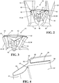
- Fan platforms 40 extend from the fan rotor 38 with each fan platform 40 in between adjacent airfoils 26.
- the fan platform 40 includes a body portion 42 and a flowpath surface portion 44.
- the body portion 42 may include a plurality of clevises 46 for attachment to the fan rotor 38.
- the flowpath surface portion 44 extends between a first and second side edge 48, 50.
- Each fan platform 40 may include an edge seal 52 along the first side edge 48 and an edge seal 52 along the second side edge 50.
- the edge seals 52 may be formed from, but not limited to, silicone.
- each edge seal 52 may be formed of a sealing flap 54, a bumper rib 56 and a bonding segment 58.
- the sealing flap 54 converges with the bonding segment 58 at a crook 59 so that the sealing flap 54 is bendable with respect to the bonding segment 58.
- the bumper rib 56 protrudes from the bonding segment 58 adjacent to the area where the sealing flap 54 converges with the bonding segment 58.
- the bonding segment 58 may be bonded to the inner surface 60 of the flowpath surface portion 44 and the bumper rib 56 may be bonded along the first side edge 48, so that the sealing flap 54 is in operative sealing contact with an adjacent airfoil 26.
- the edge seal 52 associated with the second side edge 50 may be similarly arranged such that its bonding segment 58 is bonded to the inner surface 60 and its bumper rib 56 is bonded along the second side edge 50, so that its sealing flap 54 is in operative contact with an adjacent airfoil 26.
- the bumper rib 56 acting as a locating feature for the edge seal 52, may include an end 62, which may be substantially rounded or squared.
- Portions of edge seal 52 may be covered with a fabric 64, as exemplified by the dotted lines in FIG. 4 .
- the fabric 64 may cover the portion of the bonding segment 58 that is bonded to the inner surface 60, the portion of the bumper rib 56 that is bonded to the side edges 48, 50, the portion of the bumper rib 56 which faces the airfoil 26, and the sealing flap 54.
- the fabric 64 may be, but is not limited to, a polyester weave or an aramid. The fabric 64 aids in protecting the edge seals 52 from wear and facilitates in bonding to the fan platform 40.
- the centrifugal force urges the sealing flap 54 into sealing contact with an adjacent airfoil 26 so as to prevent airflow through the spaces between the fan platforms 26 and the airfoils 26.
- the bumper rib 56 facilitates in preventing the sealing flap 54 from shifting towards the inner surface 60 so that the sealing flap 54 maintains sealing contact with the airfoil 26.
- the bumper rib 56 protects the side edges 48, 50 from direct contact with an adjacent airfoil 26. Accordingly, the bumper rib 56 prevents wear damage of the airfoils 26 and the fan platforms 40 and increases the life of these parts.
- FIG. 5 illustrates a flowchart 500 of a method of constructing an edge seal for preventing airflow through a space between a fan platform and an adjacent airfoil in a gas turbine engine.
- Box 510 shows the step of forming a bonding segment that is bondable to the fan platform.
- Another step, as shown in box 512, is forming a sealing flap that converges with the bonding segment so that the sealing flap is operatively contactable with the airfoil adjacent thereto.
- Box 514 illustrates the step of forming a bumper rib that protrudes from the bonding segment so that the bumper rib is bondable to the fan platform.
- the edge seal may be covered in fabric.
- the fabric may be a polyester weave.
- a portion of the bonding segment that is bondable to the fan platform, a portion of the bumper rib that is bondable to the fan platform, a portion of the bumper rib which faces the airfoil adjacent thereto, and the sealing flap all may be covered in fabric.
- the bumper rib may include an end, which may be rounded or squared.
- the present disclosure sets forth an edge seal for preventing airflow through a space between a fan platform and an adjacent airfoil in a gas turbine engine.
- the teachings of this disclosure can be employed to manufacture an edge seal having a bumper rib that acts as a locating feature for the edge seal.
- the bumper rib protects the fan platform from direct contact with an airfoil adjacent thereto. As such, the bumper rib prevents wear damage of the airfoils and the fan platforms and increases the life of these parts.
Landscapes
- Engineering & Computer Science (AREA)
- Mechanical Engineering (AREA)
- General Engineering & Computer Science (AREA)
- Structures Of Non-Positive Displacement Pumps (AREA)
Claims (13)
- Joint d'étanchéité de bord (52) pour empêcher l'écoulement d'air à travers un espace entre une plate-forme de soufflante (40) et un profil aérodynamique adjacent (26) dans un moteur à turbine à gaz (10), le joint d'étanchéité de bord (52) comprenant :un segment de liaison (58) pouvant être lié à une surface interne (60) de la plate-forme de soufflante (40) ;un volet d'étanchéité (54) convergeant avec le segment de liaison (58), le volet d'étanchéité (54) étant en contact opérationnel avec le profil aérodynamique adjacent (26), dans lequel le volet d'étanchéité (54) converge avec le segment de liaison (58) au niveau d'un creux (59) de sorte que le volet d'étanchéité (54) peut être plié par rapport au segment de liaison (28) ; etune nervure de tampon (56) faisant saillie depuis le segment de liaison (58) adjacente à l'endroit où le volet d'étanchéité (54) converge avec le segment de liaison (58), la nervure de tampon (56) pouvant être liée à un bord latéral (48) de la plate-forme de soufflante (40) ;dans lequel le creux (59) se trouve du côté opposé de la nervure de tampon (56) par rapport à une partie du segment de liaison (58) qui est configurée pour être liée à une surface interne (60) de la plate-forme de soufflante (40).
- Joint d'étanchéité de bord (52) selon la revendication 1, dans lequel le joint d'étanchéité de bord est recouvert d'un tissu (64).
- Joint d'étanchéité de bord (52) selon la revendication 2, dans lequel le tissu (64) recouvre une partie du segment de liaison (58) qui peut être liée à la plate-forme de soufflante (40), une partie de la nervure de tampon (56) qui peut être liée à la plate-forme de soufflante (40), une partie de la nervure de tampon (56) qui fait face au profil aérodynamique adjacent (28) et le volet d'étanchéité (54).
- Joint d'étanchéité de bord (52) selon la revendication 2 ou 3, dans lequel le tissu (64) est un tissage en polyester.
- Joint d'étanchéité de bord (52) selon la revendication 1, 2, 3 ou 4, dans lequel la nervure de tampon (56) comporte une extrémité arrondie (62), ou en variante, dans lequel la nervure de tampon (56) comporte une extrémité carrée (62).
- Moteur à turbine à gaz (10), comprenant :un rotor de soufflante (38) ;une pluralité de profils aérodynamiques (26) fixés radialement circonférentiellement autour du rotor de soufflante (38) ;une pluralité de plates-formes de soufflante (40) fixées au rotor de soufflante (38), chacune des plates-formes de soufflante (40) étant disposée entre chacun de la pluralité de profils aérodynamiques (26), chacune des plates-formes de soufflante (40) comportant un premier et un second bord latéral (48, 50) et une surface interne (60) ;une première pluralité de joints d'étanchéité de bord (52), chacun de la première pluralité de joints d'étanchéité de bord (52) comportant un premier segment de liaison (58), un premier volet d'étanchéité (54) et une première nervure de tampon (56), dans lequel le premier volet d'étanchéité (54) converge avec le premier segment de liaison (58) au niveau d'un premier creux (59) de sorte que le premier volet d'étanchéité (54) peut être plié par rapport au premier segment de liaison (28) et dans lequel la première nervure de tampon (56) fait saillie depuis le premier segment de liaison (58) adjacent à l'endroit où le premier volet d'étanchéité (54) converge avec le premier segment de liaison (58), le premier segment de liaison (58) étant lié à la surface interne (60), la première nervure de tampon (56) étant liée au premier bord latéral (48), le premier creux (59) étant du côté opposé de la première nervure de tampon (56) par rapport à la partie du premier segment de liaison (58) qui est liée à la surface interne (60), le premier volet d'étanchéité (54) étant en contact étanche opérationnel avec le profil aérodynamique (26) adjacent à celui-ci ; etune seconde pluralité de joints d'étanchéité de bord (52), chacun de la seconde pluralité de joints d'étanchéité de bord (52) comportant un second segment de liaison (58), un second volet d'étanchéité (54) et une seconde nervure de tampon (56), dans lequel le second volet d'étanchéité (54) converge avec le second segment de liaison (58) au niveau d'un second creux (59) de sorte que le second volet d'étanchéité (54) peut être plié par rapport au second segment de liaison (28) et dans lequel la seconde nervure de tampon (56) fait saillie depuis le second segment de liaison (58) adjacent à l'endroit où le second volet d'étanchéité (54) converge avec le second segment de liaison (58), le second segment de liaison (58) étant lié à la surface interne (60), la seconde nervure de tampon (56) étant liée au second bord latéral (48), le second creux (59) étant du côté opposé de la seconde nervure de tampon (56) par rapport à la partie du second segment de liaison (58) qui est liée à la surface interne (60), le second volet d'étanchéité (54) étant en contact étanche opérationnel avec le profil aérodynamique (26) adjacent à celui-ci.
- Moteur à turbine à gaz (10) selon la revendication 6, dans lequel chacun de la première et de la seconde pluralité de joints d'étanchéité de bord (52) est recouvert d'un tissu (64), et éventuellement dans lequel le tissu (64) est un tissage en polyester.
- Moteur à turbine à gaz (10) selon la revendication 7, dans lequel le tissu (64) recouvre une partie du premier segment de liaison (58) qui est liée à la surface interne (60), une partie de la première nervure de tampon (56) qui est liée au premier bord latéral (48), une partie de la première nervure de tampon (56) qui fait face au profil aérodynamique (26) adjacent à celle-ci, le premier volet d'étanchéité (54), une partie du second segment de liaison (58) qui est liée à la surface interne (60), une partie de la seconde nervure de tampon (56) qui est liée au second bord latéral (50), une partie de la seconde nervure de tampon (56) qui fait face au profil aérodynamique (26) adjacent à celle-ci, et le second volet d'étanchéité (54).
- Moteur à turbine à gaz (10) selon l'une quelconque des revendications 6 à 8, dans lequel la première nervure de tampon (56) comporte une extrémité arrondie (62) et la seconde nervure de tampon comporte une extrémité arrondie, ou en variante dans lequel la première nervure de tampon (56) comporte une extrémité carrée (62) et la seconde nervure de tampon comporte une extrémité carrée.
- Procédé de construction d'un joint d'étanchéité de bord (52) pour empêcher l'écoulement d'air à travers un espace entre une plate-forme de soufflante (40) et un profil aérodynamique adjacent (26) dans un moteur à turbine à gaz (10), comprenant :la formation d'un segment de liaison (58) qui peut être lié à une surface interne (60) de la plate-forme de soufflante (40) ;la formation d'un volet d'étanchéité (54) qui converge avec le segment de liaison (58) de sorte que le volet d'étanchéité (54) est en contact opérationnel avec le profil aérodynamique (26) adjacent à celui-ci, dans lequel le volet d'étanchéité (54) converge avec le segment de liaison (58) au niveau d'un creux (59) de sorte que le volet d'étanchéité (54) peut être plié par rapport au segment de liaison (28) ; etla formation d'une nervure de tampon (56) qui fait saillie depuis le segment de liaison (58) de sorte que la nervure de tampon (56) peut être liée à un bord latéral (48) de la plate-forme de soufflante (40), dans lequel la nervure de tampon est adjacente à l'endroit où le volet d'étanchéité (54) converge avec le segment de liaison (58) ;dans lequel le creux (59) se trouve du côté opposé de la nervure de tampon (56) par rapport à une partie du segment de liaison (58) qui est configurée pour être liée à une surface interne (60) de la plate-forme de soufflante (40).
- Procédé selon la revendication 10, comprenant en outre la couverture du joint d'étanchéité de bord (52) dans un tissu (64), et éventuellement dans lequel le tissu (64) est un tissage en polyester.
- Procédé selon la revendication 10 ou 11, comportant en outre la couverture avec un tissu (64) d'une partie du segment de liaison (58) qui peut être liée à la plate-forme de soufflante (40), d'une partie de la nervure de tampon (56) qui peut être liée à la plate-forme de soufflante (40), d'une partie de la nervure de tampon (56) qui fait face au profil aérodynamique (26) adjacent à celle-ci, et du volet d'étanchéité (54).
- Procédé selon la revendication 10, 11 ou 12, comportant en outre la formation de la nervure de tampon (56) pour comporter une extrémité arrondie (62), ou en variante, la formation de la nervure de tampon (56) pour comporter une extrémité carrée (62).
Applications Claiming Priority (2)
| Application Number | Priority Date | Filing Date | Title |
|---|---|---|---|
| US201361915883P | 2013-12-13 | 2013-12-13 | |
| PCT/US2014/051189 WO2015088593A1 (fr) | 2013-12-13 | 2014-08-15 | Joint d'étanchéité de bord de plate-forme de soufflante |
Publications (3)
| Publication Number | Publication Date |
|---|---|
| EP3080418A1 EP3080418A1 (fr) | 2016-10-19 |
| EP3080418A4 EP3080418A4 (fr) | 2017-08-09 |
| EP3080418B1 true EP3080418B1 (fr) | 2020-06-24 |
Family
ID=53371663
Family Applications (1)
| Application Number | Title | Priority Date | Filing Date |
|---|---|---|---|
| EP14869623.0A Active EP3080418B1 (fr) | 2013-12-13 | 2014-08-15 | Joint d'étanchéité de bord de plate-forme de soufflante |
Country Status (3)
| Country | Link |
|---|---|
| US (1) | US20160305439A1 (fr) |
| EP (1) | EP3080418B1 (fr) |
| WO (1) | WO2015088593A1 (fr) |
Families Citing this family (3)
| Publication number | Priority date | Publication date | Assignee | Title |
|---|---|---|---|---|
| US11028714B2 (en) | 2018-07-16 | 2021-06-08 | Raytheon Technologies Corporation | Fan platform wedge seal |
| FR3091563B1 (fr) * | 2019-01-04 | 2023-01-20 | Safran Aircraft Engines | Joint d’étanchéité amélioré de plateforme inter-aubes |
| US11268397B2 (en) | 2020-02-07 | 2022-03-08 | Raytheon Technologies Corporation | Fan blade platform seal and method for forming same |
Family Cites Families (16)
| Publication number | Priority date | Publication date | Assignee | Title |
|---|---|---|---|---|
| US4183720A (en) * | 1978-01-03 | 1980-01-15 | The United States Of America As Represented By The Secretary Of The Air Force | Composite fan blade platform double wedge centrifugal seal |
| GB9602129D0 (en) * | 1996-02-02 | 1996-04-03 | Rolls Royce Plc | Rotors for gas turbine engines |
| US6217283B1 (en) * | 1999-04-20 | 2001-04-17 | General Electric Company | Composite fan platform |
| GB9915637D0 (en) | 1999-07-06 | 1999-09-01 | Rolls Royce Plc | A rotor seal |
| GB0611031D0 (en) * | 2006-06-06 | 2006-07-12 | Rolls Royce Plc | An aerofoil stage and a seal for use therein |
| US7708520B2 (en) * | 2006-11-29 | 2010-05-04 | United Technologies Corporation | Gas turbine engine with concave pocket with knife edge seal |
| US7966808B2 (en) * | 2007-04-30 | 2011-06-28 | General Electric Company | Baffle seal for gas turbine engine thrust reverser |
| US8016297B2 (en) * | 2008-03-27 | 2011-09-13 | United Technologies Corporation | Gas turbine engine seals and engines incorporating such seals |
| GB2462810B (en) * | 2008-08-18 | 2010-07-21 | Rolls Royce Plc | Sealing means |
| GB0910752D0 (en) * | 2009-06-23 | 2009-08-05 | Rolls Royce Plc | An annulus filler for a gas turbine engine |
| GB201106278D0 (en) * | 2011-04-14 | 2011-05-25 | Rolls Royce Plc | Annulus filler system |
| US9945484B2 (en) * | 2011-05-20 | 2018-04-17 | Siemens Energy, Inc. | Turbine seals |
| FR2987086B1 (fr) * | 2012-02-22 | 2014-03-21 | Snecma | Joint lineaire de plateforme inter-aubes |
| US9297268B2 (en) * | 2012-09-06 | 2016-03-29 | United Technologies Corporation | Fan blade platform flap seal |
| US9650902B2 (en) * | 2013-01-11 | 2017-05-16 | United Technologies Corporation | Integral fan blade wear pad and platform seal |
| US9845699B2 (en) * | 2013-03-15 | 2017-12-19 | Gkn Aerospace Services Structures Corp. | Fan spacer having unitary over molded feature |
-
2014
- 2014-08-15 EP EP14869623.0A patent/EP3080418B1/fr active Active
- 2014-08-15 WO PCT/US2014/051189 patent/WO2015088593A1/fr not_active Ceased
- 2014-08-15 US US15/102,062 patent/US20160305439A1/en not_active Abandoned
Non-Patent Citations (1)
| Title |
|---|
| None * |
Also Published As
| Publication number | Publication date |
|---|---|
| EP3080418A1 (fr) | 2016-10-19 |
| US20160305439A1 (en) | 2016-10-20 |
| WO2015088593A1 (fr) | 2015-06-18 |
| EP3080418A4 (fr) | 2017-08-09 |
Similar Documents
| Publication | Publication Date | Title |
|---|---|---|
| US8118548B2 (en) | Shroud for a turbomachine | |
| JP4095060B2 (ja) | ガスタービンエンジン用静翼アセンブリ | |
| EP3090140B1 (fr) | Joint à air extérieur de pale avec jointement d'air secondaire | |
| US20180230839A1 (en) | Turbine engine shroud assembly | |
| US20140064937A1 (en) | Fan blade brush tip | |
| US10018048B2 (en) | T-shaped platform leading edge anti-rotation tabs | |
| EP3617458B1 (fr) | Joint annulaire pour un moteur à turbine à gaz | |
| EP3080418B1 (fr) | Joint d'étanchéité de bord de plate-forme de soufflante | |
| CN106194276B (zh) | 压缩机系统和翼型件组件 | |
| US10161266B2 (en) | Nozzle and nozzle assembly for gas turbine engine | |
| EP3287605B1 (fr) | Joint de bordure pour moteur à turbine à gaz | |
| US20180087395A1 (en) | Gas turbine engine | |
| US20160130964A1 (en) | Gas turbine engine flow control device | |
| US20180080335A1 (en) | Gas turbine engine sealing arrangement | |
| US10309224B2 (en) | Split ring spring dampers for gas turbine rotor assemblies | |
| US20160230580A1 (en) | Recirculation seal for use in a gas turbine engine | |
| US11536144B2 (en) | Rotor blade damping structures | |
| US20200063590A1 (en) | Sealing member for gas turbine engine |
Legal Events
| Date | Code | Title | Description |
|---|---|---|---|
| PUAI | Public reference made under article 153(3) epc to a published international application that has entered the european phase |
Free format text: ORIGINAL CODE: 0009012 |
|
| 17P | Request for examination filed |
Effective date: 20160713 |
|
| AK | Designated contracting states |
Kind code of ref document: A1 Designated state(s): AL AT BE BG CH CY CZ DE DK EE ES FI FR GB GR HR HU IE IS IT LI LT LU LV MC MK MT NL NO PL PT RO RS SE SI SK SM TR |
|
| AX | Request for extension of the european patent |
Extension state: BA ME |
|
| RAP1 | Party data changed (applicant data changed or rights of an application transferred) |
Owner name: UNITED TECHNOLOGIES CORPORATION |
|
| DAX | Request for extension of the european patent (deleted) | ||
| A4 | Supplementary search report drawn up and despatched |
Effective date: 20170712 |
|
| RIC1 | Information provided on ipc code assigned before grant |
Ipc: F02C 7/28 20060101AFI20170706BHEP Ipc: F04D 29/08 20060101ALI20170706BHEP Ipc: F04D 29/32 20060101ALI20170706BHEP Ipc: F04D 29/38 20060101ALI20170706BHEP Ipc: F04D 29/34 20060101ALI20170706BHEP Ipc: F04D 19/00 20060101ALI20170706BHEP Ipc: F01D 11/00 20060101ALI20170706BHEP Ipc: F02K 3/06 20060101ALI20170706BHEP |
|
| STAA | Information on the status of an ep patent application or granted ep patent |
Free format text: STATUS: EXAMINATION IS IN PROGRESS |
|
| 17Q | First examination report despatched |
Effective date: 20180723 |
|
| GRAP | Despatch of communication of intention to grant a patent |
Free format text: ORIGINAL CODE: EPIDOSNIGR1 |
|
| STAA | Information on the status of an ep patent application or granted ep patent |
Free format text: STATUS: GRANT OF PATENT IS INTENDED |
|
| INTG | Intention to grant announced |
Effective date: 20200108 |
|
| GRAS | Grant fee paid |
Free format text: ORIGINAL CODE: EPIDOSNIGR3 |
|
| GRAA | (expected) grant |
Free format text: ORIGINAL CODE: 0009210 |
|
| STAA | Information on the status of an ep patent application or granted ep patent |
Free format text: STATUS: THE PATENT HAS BEEN GRANTED |
|
| AK | Designated contracting states |
Kind code of ref document: B1 Designated state(s): AL AT BE BG CH CY CZ DE DK EE ES FI FR GB GR HR HU IE IS IT LI LT LU LV MC MK MT NL NO PL PT RO RS SE SI SK SM TR |
|
| REG | Reference to a national code |
Ref country code: GB Ref legal event code: FG4D |
|
| REG | Reference to a national code |
Ref country code: CH Ref legal event code: EP |
|
| REG | Reference to a national code |
Ref country code: AT Ref legal event code: REF Ref document number: 1284109 Country of ref document: AT Kind code of ref document: T Effective date: 20200715 |
|
| REG | Reference to a national code |
Ref country code: DE Ref legal event code: R096 Ref document number: 602014067103 Country of ref document: DE |
|
| REG | Reference to a national code |
Ref country code: IE Ref legal event code: FG4D |
|
| PG25 | Lapsed in a contracting state [announced via postgrant information from national office to epo] |
Ref country code: LT Free format text: LAPSE BECAUSE OF FAILURE TO SUBMIT A TRANSLATION OF THE DESCRIPTION OR TO PAY THE FEE WITHIN THE PRESCRIBED TIME-LIMIT Effective date: 20200624 Ref country code: SE Free format text: LAPSE BECAUSE OF FAILURE TO SUBMIT A TRANSLATION OF THE DESCRIPTION OR TO PAY THE FEE WITHIN THE PRESCRIBED TIME-LIMIT Effective date: 20200624 Ref country code: FI Free format text: LAPSE BECAUSE OF FAILURE TO SUBMIT A TRANSLATION OF THE DESCRIPTION OR TO PAY THE FEE WITHIN THE PRESCRIBED TIME-LIMIT Effective date: 20200624 Ref country code: GR Free format text: LAPSE BECAUSE OF FAILURE TO SUBMIT A TRANSLATION OF THE DESCRIPTION OR TO PAY THE FEE WITHIN THE PRESCRIBED TIME-LIMIT Effective date: 20200925 Ref country code: NO Free format text: LAPSE BECAUSE OF FAILURE TO SUBMIT A TRANSLATION OF THE DESCRIPTION OR TO PAY THE FEE WITHIN THE PRESCRIBED TIME-LIMIT Effective date: 20200924 |
|
| REG | Reference to a national code |
Ref country code: LT Ref legal event code: MG4D |
|
| PG25 | Lapsed in a contracting state [announced via postgrant information from national office to epo] |
Ref country code: LV Free format text: LAPSE BECAUSE OF FAILURE TO SUBMIT A TRANSLATION OF THE DESCRIPTION OR TO PAY THE FEE WITHIN THE PRESCRIBED TIME-LIMIT Effective date: 20200624 Ref country code: RS Free format text: LAPSE BECAUSE OF FAILURE TO SUBMIT A TRANSLATION OF THE DESCRIPTION OR TO PAY THE FEE WITHIN THE PRESCRIBED TIME-LIMIT Effective date: 20200624 Ref country code: BG Free format text: LAPSE BECAUSE OF FAILURE TO SUBMIT A TRANSLATION OF THE DESCRIPTION OR TO PAY THE FEE WITHIN THE PRESCRIBED TIME-LIMIT Effective date: 20200924 Ref country code: HR Free format text: LAPSE BECAUSE OF FAILURE TO SUBMIT A TRANSLATION OF THE DESCRIPTION OR TO PAY THE FEE WITHIN THE PRESCRIBED TIME-LIMIT Effective date: 20200624 |
|
| REG | Reference to a national code |
Ref country code: NL Ref legal event code: MP Effective date: 20200624 |
|
| REG | Reference to a national code |
Ref country code: AT Ref legal event code: MK05 Ref document number: 1284109 Country of ref document: AT Kind code of ref document: T Effective date: 20200624 |
|
| PG25 | Lapsed in a contracting state [announced via postgrant information from national office to epo] |
Ref country code: NL Free format text: LAPSE BECAUSE OF FAILURE TO SUBMIT A TRANSLATION OF THE DESCRIPTION OR TO PAY THE FEE WITHIN THE PRESCRIBED TIME-LIMIT Effective date: 20200624 Ref country code: AL Free format text: LAPSE BECAUSE OF FAILURE TO SUBMIT A TRANSLATION OF THE DESCRIPTION OR TO PAY THE FEE WITHIN THE PRESCRIBED TIME-LIMIT Effective date: 20200624 |
|
| PG25 | Lapsed in a contracting state [announced via postgrant information from national office to epo] |
Ref country code: CZ Free format text: LAPSE BECAUSE OF FAILURE TO SUBMIT A TRANSLATION OF THE DESCRIPTION OR TO PAY THE FEE WITHIN THE PRESCRIBED TIME-LIMIT Effective date: 20200624 Ref country code: RO Free format text: LAPSE BECAUSE OF FAILURE TO SUBMIT A TRANSLATION OF THE DESCRIPTION OR TO PAY THE FEE WITHIN THE PRESCRIBED TIME-LIMIT Effective date: 20200624 Ref country code: SM Free format text: LAPSE BECAUSE OF FAILURE TO SUBMIT A TRANSLATION OF THE DESCRIPTION OR TO PAY THE FEE WITHIN THE PRESCRIBED TIME-LIMIT Effective date: 20200624 Ref country code: IT Free format text: LAPSE BECAUSE OF FAILURE TO SUBMIT A TRANSLATION OF THE DESCRIPTION OR TO PAY THE FEE WITHIN THE PRESCRIBED TIME-LIMIT Effective date: 20200624 Ref country code: AT Free format text: LAPSE BECAUSE OF FAILURE TO SUBMIT A TRANSLATION OF THE DESCRIPTION OR TO PAY THE FEE WITHIN THE PRESCRIBED TIME-LIMIT Effective date: 20200624 Ref country code: EE Free format text: LAPSE BECAUSE OF FAILURE TO SUBMIT A TRANSLATION OF THE DESCRIPTION OR TO PAY THE FEE WITHIN THE PRESCRIBED TIME-LIMIT Effective date: 20200624 Ref country code: ES Free format text: LAPSE BECAUSE OF FAILURE TO SUBMIT A TRANSLATION OF THE DESCRIPTION OR TO PAY THE FEE WITHIN THE PRESCRIBED TIME-LIMIT Effective date: 20200624 Ref country code: PT Free format text: LAPSE BECAUSE OF FAILURE TO SUBMIT A TRANSLATION OF THE DESCRIPTION OR TO PAY THE FEE WITHIN THE PRESCRIBED TIME-LIMIT Effective date: 20201026 |
|
| PG25 | Lapsed in a contracting state [announced via postgrant information from national office to epo] |
Ref country code: SK Free format text: LAPSE BECAUSE OF FAILURE TO SUBMIT A TRANSLATION OF THE DESCRIPTION OR TO PAY THE FEE WITHIN THE PRESCRIBED TIME-LIMIT Effective date: 20200624 Ref country code: PL Free format text: LAPSE BECAUSE OF FAILURE TO SUBMIT A TRANSLATION OF THE DESCRIPTION OR TO PAY THE FEE WITHIN THE PRESCRIBED TIME-LIMIT Effective date: 20200624 Ref country code: IS Free format text: LAPSE BECAUSE OF FAILURE TO SUBMIT A TRANSLATION OF THE DESCRIPTION OR TO PAY THE FEE WITHIN THE PRESCRIBED TIME-LIMIT Effective date: 20201024 |
|
| RAP2 | Party data changed (patent owner data changed or rights of a patent transferred) |
Owner name: RAYTHEON TECHNOLOGIES CORPORATION |
|
| REG | Reference to a national code |
Ref country code: DE Ref legal event code: R097 Ref document number: 602014067103 Country of ref document: DE |
|
| PG25 | Lapsed in a contracting state [announced via postgrant information from national office to epo] |
Ref country code: MC Free format text: LAPSE BECAUSE OF FAILURE TO SUBMIT A TRANSLATION OF THE DESCRIPTION OR TO PAY THE FEE WITHIN THE PRESCRIBED TIME-LIMIT Effective date: 20200624 |
|
| REG | Reference to a national code |
Ref country code: CH Ref legal event code: PL |
|
| PG25 | Lapsed in a contracting state [announced via postgrant information from national office to epo] |
Ref country code: CH Free format text: LAPSE BECAUSE OF NON-PAYMENT OF DUE FEES Effective date: 20200831 Ref country code: DK Free format text: LAPSE BECAUSE OF FAILURE TO SUBMIT A TRANSLATION OF THE DESCRIPTION OR TO PAY THE FEE WITHIN THE PRESCRIBED TIME-LIMIT Effective date: 20200624 Ref country code: LU Free format text: LAPSE BECAUSE OF NON-PAYMENT OF DUE FEES Effective date: 20200815 Ref country code: LI Free format text: LAPSE BECAUSE OF NON-PAYMENT OF DUE FEES Effective date: 20200831 |
|
| PLBE | No opposition filed within time limit |
Free format text: ORIGINAL CODE: 0009261 |
|
| STAA | Information on the status of an ep patent application or granted ep patent |
Free format text: STATUS: NO OPPOSITION FILED WITHIN TIME LIMIT |
|
| REG | Reference to a national code |
Ref country code: BE Ref legal event code: MM Effective date: 20200831 |
|
| 26N | No opposition filed |
Effective date: 20210325 |
|
| PG25 | Lapsed in a contracting state [announced via postgrant information from national office to epo] |
Ref country code: SI Free format text: LAPSE BECAUSE OF FAILURE TO SUBMIT A TRANSLATION OF THE DESCRIPTION OR TO PAY THE FEE WITHIN THE PRESCRIBED TIME-LIMIT Effective date: 20200624 Ref country code: IE Free format text: LAPSE BECAUSE OF NON-PAYMENT OF DUE FEES Effective date: 20200815 Ref country code: BE Free format text: LAPSE BECAUSE OF NON-PAYMENT OF DUE FEES Effective date: 20200831 |
|
| PG25 | Lapsed in a contracting state [announced via postgrant information from national office to epo] |
Ref country code: TR Free format text: LAPSE BECAUSE OF FAILURE TO SUBMIT A TRANSLATION OF THE DESCRIPTION OR TO PAY THE FEE WITHIN THE PRESCRIBED TIME-LIMIT Effective date: 20200624 Ref country code: MT Free format text: LAPSE BECAUSE OF FAILURE TO SUBMIT A TRANSLATION OF THE DESCRIPTION OR TO PAY THE FEE WITHIN THE PRESCRIBED TIME-LIMIT Effective date: 20200624 Ref country code: CY Free format text: LAPSE BECAUSE OF FAILURE TO SUBMIT A TRANSLATION OF THE DESCRIPTION OR TO PAY THE FEE WITHIN THE PRESCRIBED TIME-LIMIT Effective date: 20200624 |
|
| PG25 | Lapsed in a contracting state [announced via postgrant information from national office to epo] |
Ref country code: MK Free format text: LAPSE BECAUSE OF FAILURE TO SUBMIT A TRANSLATION OF THE DESCRIPTION OR TO PAY THE FEE WITHIN THE PRESCRIBED TIME-LIMIT Effective date: 20200624 |
|
| P01 | Opt-out of the competence of the unified patent court (upc) registered |
Effective date: 20230520 |
|
| REG | Reference to a national code |
Ref country code: DE Ref legal event code: R081 Ref document number: 602014067103 Country of ref document: DE Owner name: RTX CORPORATION (N.D.GES.D. STAATES DELAWARE),, US Free format text: FORMER OWNER: UNITED TECHNOLOGIES CORPORATION, FARMINGTON, CONN., US |
|
| PGFP | Annual fee paid to national office [announced via postgrant information from national office to epo] |
Ref country code: DE Payment date: 20250724 Year of fee payment: 12 |
|
| PGFP | Annual fee paid to national office [announced via postgrant information from national office to epo] |
Ref country code: GB Payment date: 20250724 Year of fee payment: 12 |
|
| PGFP | Annual fee paid to national office [announced via postgrant information from national office to epo] |
Ref country code: FR Payment date: 20250723 Year of fee payment: 12 |