EP3080444B1 - Système et procédé pour réduire des charges d'oscillation de turbine éolienne - Google Patents
Système et procédé pour réduire des charges d'oscillation de turbine éolienne Download PDFInfo
- Publication number
- EP3080444B1 EP3080444B1 EP13898996.7A EP13898996A EP3080444B1 EP 3080444 B1 EP3080444 B1 EP 3080444B1 EP 13898996 A EP13898996 A EP 13898996A EP 3080444 B1 EP3080444 B1 EP 3080444B1
- Authority
- EP
- European Patent Office
- Prior art keywords
- wind
- wind turbine
- variance
- oscillation
- operating
- Prior art date
- Legal status (The legal status is an assumption and is not a legal conclusion. Google has not performed a legal analysis and makes no representation as to the accuracy of the status listed.)
- Active
Links
Images


Classifications
-
- F—MECHANICAL ENGINEERING; LIGHTING; HEATING; WEAPONS; BLASTING
- F03—MACHINES OR ENGINES FOR LIQUIDS; WIND, SPRING, OR WEIGHT MOTORS; PRODUCING MECHANICAL POWER OR A REACTIVE PROPULSIVE THRUST, NOT OTHERWISE PROVIDED FOR
- F03D—WIND MOTORS
- F03D7/00—Controlling wind motors
- F03D7/02—Controlling wind motors the wind motors having rotation axis substantially parallel to the air flow entering the rotor
- F03D7/0296—Controlling wind motors the wind motors having rotation axis substantially parallel to the air flow entering the rotor to prevent, counteract or reduce noise emissions
-
- F—MECHANICAL ENGINEERING; LIGHTING; HEATING; WEAPONS; BLASTING
- F03—MACHINES OR ENGINES FOR LIQUIDS; WIND, SPRING, OR WEIGHT MOTORS; PRODUCING MECHANICAL POWER OR A REACTIVE PROPULSIVE THRUST, NOT OTHERWISE PROVIDED FOR
- F03D—WIND MOTORS
- F03D15/00—Transmission of mechanical power
- F03D15/10—Transmission of mechanical power using gearing not limited to rotary motion, e.g. with oscillating or reciprocating members
-
- F—MECHANICAL ENGINEERING; LIGHTING; HEATING; WEAPONS; BLASTING
- F03—MACHINES OR ENGINES FOR LIQUIDS; WIND, SPRING, OR WEIGHT MOTORS; PRODUCING MECHANICAL POWER OR A REACTIVE PROPULSIVE THRUST, NOT OTHERWISE PROVIDED FOR
- F03D—WIND MOTORS
- F03D17/00—Monitoring or testing of wind motors, e.g. diagnostics
-
- F—MECHANICAL ENGINEERING; LIGHTING; HEATING; WEAPONS; BLASTING
- F03—MACHINES OR ENGINES FOR LIQUIDS; WIND, SPRING, OR WEIGHT MOTORS; PRODUCING MECHANICAL POWER OR A REACTIVE PROPULSIVE THRUST, NOT OTHERWISE PROVIDED FOR
- F03D—WIND MOTORS
- F03D7/00—Controlling wind motors
- F03D7/02—Controlling wind motors the wind motors having rotation axis substantially parallel to the air flow entering the rotor
- F03D7/022—Adjusting aerodynamic properties of the blades
- F03D7/0224—Adjusting blade pitch
-
- F—MECHANICAL ENGINEERING; LIGHTING; HEATING; WEAPONS; BLASTING
- F03—MACHINES OR ENGINES FOR LIQUIDS; WIND, SPRING, OR WEIGHT MOTORS; PRODUCING MECHANICAL POWER OR A REACTIVE PROPULSIVE THRUST, NOT OTHERWISE PROVIDED FOR
- F03D—WIND MOTORS
- F03D7/00—Controlling wind motors
- F03D7/02—Controlling wind motors the wind motors having rotation axis substantially parallel to the air flow entering the rotor
- F03D7/0244—Controlling wind motors the wind motors having rotation axis substantially parallel to the air flow entering the rotor for braking
-
- F—MECHANICAL ENGINEERING; LIGHTING; HEATING; WEAPONS; BLASTING
- F03—MACHINES OR ENGINES FOR LIQUIDS; WIND, SPRING, OR WEIGHT MOTORS; PRODUCING MECHANICAL POWER OR A REACTIVE PROPULSIVE THRUST, NOT OTHERWISE PROVIDED FOR
- F03D—WIND MOTORS
- F03D7/00—Controlling wind motors
- F03D7/02—Controlling wind motors the wind motors having rotation axis substantially parallel to the air flow entering the rotor
- F03D7/04—Automatic control; Regulation
- F03D7/042—Automatic control; Regulation by means of an electrical or electronic controller
-
- F—MECHANICAL ENGINEERING; LIGHTING; HEATING; WEAPONS; BLASTING
- F03—MACHINES OR ENGINES FOR LIQUIDS; WIND, SPRING, OR WEIGHT MOTORS; PRODUCING MECHANICAL POWER OR A REACTIVE PROPULSIVE THRUST, NOT OTHERWISE PROVIDED FOR
- F03D—WIND MOTORS
- F03D9/00—Adaptations of wind motors for special use; Combinations of wind motors with apparatus driven thereby; Wind motors specially adapted for installation in particular locations
- F03D9/20—Wind motors characterised by the driven apparatus
- F03D9/25—Wind motors characterised by the driven apparatus the apparatus being an electrical generator
-
- G—PHYSICS
- G05—CONTROLLING; REGULATING
- G05B—CONTROL OR REGULATING SYSTEMS IN GENERAL; FUNCTIONAL ELEMENTS OF SUCH SYSTEMS; MONITORING OR TESTING ARRANGEMENTS FOR SUCH SYSTEMS OR ELEMENTS
- G05B19/00—Program-control systems
- G05B19/02—Program-control systems electric
- G05B19/04—Program control other than numerical control, i.e. in sequence controllers or logic controllers
- G05B19/042—Program control other than numerical control, i.e. in sequence controllers or logic controllers using digital processors
-
- F—MECHANICAL ENGINEERING; LIGHTING; HEATING; WEAPONS; BLASTING
- F05—INDEXING SCHEMES RELATING TO ENGINES OR PUMPS IN VARIOUS SUBCLASSES OF CLASSES F01-F04
- F05B—INDEXING SCHEME RELATING TO WIND, SPRING, WEIGHT, INERTIA OR LIKE MOTORS, TO MACHINES OR ENGINES FOR LIQUIDS COVERED BY SUBCLASSES F03B, F03D AND F03G
- F05B2270/00—Control
- F05B2270/30—Control parameters, e.g. input parameters
- F05B2270/334—Vibration measurements
-
- G—PHYSICS
- G05—CONTROLLING; REGULATING
- G05B—CONTROL OR REGULATING SYSTEMS IN GENERAL; FUNCTIONAL ELEMENTS OF SUCH SYSTEMS; MONITORING OR TESTING ARRANGEMENTS FOR SUCH SYSTEMS OR ELEMENTS
- G05B2219/00—Program-control systems
- G05B2219/20—Pc systems
- G05B2219/26—Pc applications
- G05B2219/2619—Wind turbines
-
- Y—GENERAL TAGGING OF NEW TECHNOLOGICAL DEVELOPMENTS; GENERAL TAGGING OF CROSS-SECTIONAL TECHNOLOGIES SPANNING OVER SEVERAL SECTIONS OF THE IPC; TECHNICAL SUBJECTS COVERED BY FORMER USPC CROSS-REFERENCE ART COLLECTIONS [XRACs] AND DIGESTS
- Y02—TECHNOLOGIES OR APPLICATIONS FOR MITIGATION OR ADAPTATION AGAINST CLIMATE CHANGE
- Y02E—REDUCTION OF GREENHOUSE GAS [GHG] EMISSIONS, RELATED TO ENERGY GENERATION, TRANSMISSION OR DISTRIBUTION
- Y02E10/00—Energy generation through renewable energy sources
- Y02E10/70—Wind energy
- Y02E10/72—Wind turbines with rotation axis in wind direction
Definitions
- the present subject matter relates generally to wind turbines and, more particularly, to a system and method for reducing oscillation loads in a wind turbine induced by high turbulence and/or combined with other environmental conditions.
- Wind power is considered one of the cleanest, most environmentally friendly energy sources presently available and wind turbines have gained increased attention in this regard.
- a modern wind turbine typically includes a tower, a generator, a gearbox, a nacelle, and one or more rotor blades.
- the rotor blades are the primary elements for converting wind energy into electrical energy.
- the blades typically have the cross-sectional profile of an airfoil such that, during operation, air flows over the blade producing a pressure difference between its sides. Consequently, a lift force, which is directed from the pressure side towards the suction side, acts on the blade. The lift force generates torque on the main rotor shaft, which is geared to a generator for producing electricity.
- oscillations occur in various wind turbine components as the generator speed is increased to rated speed.
- the oscillations of the individual components have a tendency to excite the wind turbine when the frequency of the oscillations equals one of the resonance frequencies of the wind turbine, which is the frequency at which the response amplitude is a relative maximum.
- the term "resonance" is meant to encompass the tendency of a wind turbine component to oscillate with greater amplitude at some frequencies than at others and/or a vibration of large amplitude produced by a relatively small vibration near the same frequency of vibration as the natural frequency of the resonating system or band of frequencies.
- the resonance may be due to the coupling effect of the tower with the pitch drive mechanism and/or the coupling effect of the tower with the speed regulator. At such frequencies, even small periodic excitation actions can produce large amplitude oscillations, because the component is capable of storing vibrational energy.
- various control technologies have been implemented to control the generator speed of the wind turbine during start-up to avoid components from oscillating at one of their resonance frequencies.
- various control technologies determine a speed exclusion zone for the generator and prevent the generator speed from operating in this zone for longer than a predetermined time period to avoid exciting the system.
- the speed exclusion zone of a wind turbine typically refers to a region within the variable-speed region of the wind turbine where the generator is not allowed to operate for sustained periods.
- Such control strategies are typically only concerned with start-up conditions of the wind turbine and do not consider oscillations caused by high turbulence intensity and/or other environmental conditions combined with wind turbine operational status that occur during subsequent operation.
- the generator speed correspondingly varies and can excite resonance frequencies of various wind turbine components, thereby causing oscillation and/or resonance loads that can damage the wind turbine.
- the rotor blades tend to experience edgewise oscillations or vibrations and/or resonance behavior at high turbulence that increases the blade-edge loads above design loads.
- Rotor blade edge-wise oscillations occur in the chord-wise direction of the rotor blade between the leading edge and the trailing edge and can damage the blade due to little damping directed to such oscillations.
- Further control strategies reduce and/or prevent various wind turbine component loading by shutting down the wind turbine above a certain (cut out) wind speed in an effort to minimize loads. Though this strategy prevents damaging loads that might occur due to the higher turbulence in the wind, a disadvantage is the lack of energy capture in the region above the cut out wind speed. Also, a brief increase in wind speed might trigger a turbine shutdown, while the recovery to normal power production may take some time. On the same token, the occurrence of high turbulence at rated wind speeds will also increase the likelihood of triggering a turbine shutdown. Still further control technologies reduce and/or prevent various wind turbine component loading by measuring a wind speed via a sensor and implementing a control a control action when wind speeds indicate turbulent conditions. Such strategies, however, do not consider resonance and/or oscillation loads as described herein. Further control strategies are disclosed in US 2010/158687 A1 .
- the step of determining the at least one wind parameter may include estimating the wind parameter utilizing any combination of the following: one or more operating conditions of the wind turbine, a plurality of equations, one or more aerodynamic performance maps, one or more look-up tables (LUTs), one or more adaptive parameters of the wind turbine and/or derivations from any form of rotor/generator speed that is calculated or derived with respect to the pitch angles and/or the generator flux.
- the adaptive parameters of the wind turbine may be any changing parameter of the wind turbine, including, but not limited to previous operating experience, historical data, adaptive inputs, coefficients, gains, losses, constants, or similar.
- the step of determining the at least one wind parameter includes filtering a plurality of wind parameters to more accurately determine the wind parameter.
- the operating conditions may be any of the following: a pitch angle/speed, rotor/generator speed, a power output, a torque/generator flux measurement output, or similar.
- the system may further include one or more sensors configured to measure one or more wind parameters and/or the operating conditions.
- the processor may further include one or more low-pass filters configured to filter any of the following: a plurality of measured and/or estimated wind parameters and/or one or more operating set points.
- the processor may further include one or more S-functions, wherein the operating set point is an input for the S-function such that the S-function is configured to stabilize a transition to the operating set point.
- the present subject matter is directed to a system and method for reducing oscillation loads of a wind turbine due to high turbulence and/or combined with other environmental conditions.
- the environmental conditions can be any environmental condition that causes an oscillation on one or more wind turbine components, including, wind peaks, wind shear, changes in wind direction, air density, and/or similar.
- the present disclosure allows the wind turbine to continue to operate at higher cut-out wind speeds under high turbulence intensity levels.
- the present subject matter is configured to detect or infer an oscillation occurring at a wind turbine component, e.g. a rotor blade, by determining a wind speed and corresponding generator speed and determining a variance in either the wind speed and/or the generator speed.
- oscillations are meant to encompass any back-and-forth, up-and-down, and/or side-to-side movements of a wind turbine component including, but not limited to, any movements due to tower shadow, tower dam, wind shear, and/or turbulence intensity.
- the oscillations may also encompass any form of direct and/or indirect measurement by one or more sensors (e.g. accelerometers and/or gauges) that can be mounted in the wind turbine.
- the system is capable of modifying the frequency such that the modified frequency is no longer within the frequency band so as to prevent oscillation loads from damaging the wind turbine component.
- the present disclosure utilizes a combination of estimated and/or real wind speed and generator speed/wind speed variance to de-rate or up-rate the wind turbine (e.g. by adjusting the generator speed, torque speed, or both) to avoid edge-wise blade resonance and reduce blade edge loads.
- the de-rate/up-rate may consider the electrical capability of the wind turbine such that a modified operating set point, e.g. a torque demand and/or a generator speed demand, is actually achievable.
- the present disclosure may utilize a series of low pass filters and S-functions to make transitioning to a selected operating set point smooth and stable.
- the present disclosure reduces and/or prevents oscillation loads induced by high turbulence intensity from damaging the wind turbine, while also increasing the cut-out wind speed to help customers secure a higher Annual Energy Production (AEP).
- AEP Annual Energy Production
- the present disclosure may be implemented using existing components of the wind turbine. As such, a user is not required to purchase, install, and maintain new equipment.
- the system may be integrated with a broader control system, such as, but not limiting of, a wind turbine control system, a plant control system, a remote monitoring system, or combinations thereof.
- FIG. 1 illustrates a perspective view of one embodiment of a wind turbine 10 that may implement the control technology according to the present disclosure.
- the wind turbine 10 generally includes a tower 12 extending from a support surface 14, a nacelle 16 mounted on the tower 12, and a rotor 18 coupled to the nacelle 16.
- the rotor 18 includes a rotatable hub 20 and at least one rotor blade 22 coupled to and extending outwardly from the hub 20.
- the rotor 18 includes three rotor blades 22.
- the rotor 18 may include more or less than three rotor blades 22.
- Each rotor blade 22 may be spaced about the hub 20 to facilitate rotating the rotor 18 to enable kinetic energy to be transferred from the wind into usable mechanical energy, and subsequently, electrical energy.
- the hub 20 may be rotatably coupled to an electric generator 24 ( FIG. 2 ) positioned within the nacelle 16 to permit electrical energy to be produced.
- the wind turbine 10 may also include a wind turbine controller 26 centralized within the nacelle 16.
- the controller 26 may be located within any other component of the wind turbine 10 or at a location outside the wind turbine.
- the controller 26 may be communicatively coupled to any number of the components of the wind turbine 10 in order to operate such components and/or to implement the steps of the present disclosure as described herein.
- the controller 26 may include a computer or other suitable processing unit.
- the controller 26 may include suitable computer-readable instructions that, when implemented, configure the controller 26 to perform various different functions, such as receiving, transmitting and/or executing wind turbine control signals.
- controller 26 may generally be configured to control the various operating modes (e.g., start-up or shut-down sequences), de-rate or up-rate the wind turbine, control various components of the wind turbine 10, and/or implement the various steps of the method described herein as will be discussed in more detail below.
- various operating modes e.g., start-up or shut-down sequences
- de-rate or up-rate the wind turbine control various components of the wind turbine 10
- the generator 24 may be coupled to the rotor 18 for producing electrical power from the rotational energy generated by the rotor 18.
- the rotor 18 may include a rotor shaft 34 coupled to the hub 20 for rotation therewith.
- the rotor shaft 34 may, in turn, be rotatably coupled to a generator shaft 36 of the generator 24 through a gearbox 38.
- the rotor shaft 34 may provide a low speed, high torque input to the gearbox 38 in response to rotation of the rotor blades 22 and the hub 20.
- the gearbox 38 may then be configured to convert the low speed, high torque input to a high speed, low torque output to drive the generator shaft 36 and, thus, the generator 24.
- the wind turbine 10 may also include a converter (not shown) configured to connect the generator 24 to the grid and to ensure a constant energy supply. More specifically, the converter is configured to convert a predetermined torque demand into rotational power to drive the generator 24.
- Each rotor blade 22 may also include a pitch adjustment mechanism 32 configured to rotate each rotor blade 22 about its pitch axis 28.
- each pitch adjustment mechanism 32 may include a pitch drive motor 40 (e.g., any suitable electric, hydraulic, or pneumatic motor), a pitch drive gearbox 42, and a pitch drive pinion 44.
- the pitch drive motor 40 may be coupled to the pitch drive gearbox 42 so that the pitch drive motor 40 imparts mechanical force to the pitch drive gearbox 42.
- the pitch drive gearbox 42 may be coupled to the pitch drive pinion 44 for rotation therewith.
- the pitch drive pinion 44 may, in turn, be in rotational engagement with a pitch bearing 46 coupled between the hub 20 and a corresponding rotor blade 22 such that rotation of the pitch drive pinion 44 causes rotation of the pitch bearing 46.
- rotation of the pitch drive motor 40 drives the pitch drive gearbox 42 and the pitch drive pinion 44, thereby rotating the pitch bearing 46 and the rotor blade 22 about the pitch axis 28.
- the wind turbine 10 may include one or more yaw drive mechanisms 66 communicatively coupled to the controller 26, with each yaw drive mechanism(s) 66 being configured to change the angle of the nacelle 16 relative to the wind (e.g., by engaging a yaw bearing 68 of the wind turbine 10).
- the wind turbine 10 may also include one or more sensors 48, 50, 52 configured to measure or monitor various wind parameters and/or one or more operating conditions of the wind turbine 10.
- the sensors may include blade sensors 48 for measuring a pitch angle of one of the rotor blades 22; generator sensors 50 for monitoring the generator 24 (e.g. torque, rotational speed, acceleration and/or the power output); and/or various wind sensors 52 for measuring various wind parameters, such as wind speed, wind peaks, wind turbulence, wind shear, changes in wind direction, air density, or similar. It should also be understood that any number or type of sensors may be employed and at any location.
- the sensors may be Micro Inertial Measurement Units (MIMUs), strain gauges, accelerometers, pressure sensors, angle of attack sensors, vibration sensors, Light Detecting and Ranging (LIDAR) sensors, camera systems, fiber optic systems, anemometers, wind vanes, Sonic Detection and Ranging (SODAR) sensors, infra lasers, radiometers, pitot tubes, rawinsondes, other optical sensors, and/or any other suitable sensors.
- MIMUs Micro Inertial Measurement Units
- LIDAR Light Detecting and Ranging
- SODAR Sonic Detection and Ranging
- the various sensors may be configured to provide a direct measurement of the parameters being monitored or an indirect measurement of such parameters.
- the sensors may, for example, be used to generate signals relating to the parameter being monitored, which can then be utilized by the controller 26 to determine the actual parameter.
- the controller 26 may include one or more processor(s) 58, a wind parameter estimator 56, and associated memory device(s) 60 configured to perform a variety of computer-implemented functions (e.g., performing the methods, steps, calculations and the like and storing relevant data as disclosed herein).
- the one or more processor(s) 58 may operate independently from the controller 56.
- the controller 26 may include a communications module 62 to facilitate communications between the controller 26 and the various components of the wind turbine 10.
- the communications module 62 may include a sensor interface 64 (e.g., one or more analog-to-digital converters) to permit signals transmitted from the sensors 48, 50, 52 to be converted into signals that can be understood and processed by the processors 58.
- the sensors 48, 50, 52 may be communicatively coupled to the communications module 62 using any suitable means.
- the sensors 48, 50, 52 are coupled to the sensor interface 64 via a wired connection.
- the sensors 48, 50, 52 may be coupled to the sensor interface 64 via a wireless connection, such as by using any suitable wireless communications protocol known in the art.
- the term "processor” refers not only to integrated circuits referred to in the art as being included in a computer, but also refers to a controller, a microcontroller, a microcomputer, a programmable logic controller (PLC), an application specific integrated circuit, and other programmable circuits.
- the memory device(s) 60 may generally comprise memory element(s) including, but not limited to, computer readable medium (e.g., random access memory (RAM)), computer readable non-volatile medium (e.g., a flash memory), a floppy disk, a compact disc-read only memory (CD-ROM), a magneto-optical disk (MOD), a digital versatile disc (DVD) and/or other suitable memory elements.
- RAM random access memory
- CD-ROM compact disc-read only memory
- MOD magneto-optical disk
- DVD digital versatile disc
- Such memory device(s) 60 may generally be configured to store suitable computer-readable instructions that, when implemented by the processor(s) 58, configure the controller 26 to perform various functions including, but not limited to, determining one or more wind parameters of the wind turbine 10, determining and selecting an appropriate operational set point for various wind turbine components, transmitting suitable control signals to implement control actions to prevent loads from damaging the wind turbine, and/or various other suitable computer-implemented functions.
- the wind parameter estimator 56 may be considered software that utilizes a plurality of operating conditions to calculate, in real-time, the current wind parameter.
- the wind parameter estimator 56 may comprise firmware that includes the software, which may be executed by the processor 58. Further, the wind parameter estimator 56 may be in communication the various sensors and devices of the wind turbine 10.
- the processor 58 may receive one or more signals from the sensors 48, 50, 52 that are representative of one or more wind parameters or one or more operating conditions of the wind turbine 10.
- the wind parameters may be reflective of a wind gust, a wind speed, a wind direction, a wind acceleration, a wind turbulence, a wind shear, a wind veer, a wake, or similar.
- the wind parameter estimator 56 may estimate the wind parameter(s) as a function of various operating data.
- the operating data may include any one or combination of the following: a pitch angle, a generator speed, a power output, a torque demand and/or speed, a tip speed ratio, a rotor speed, or similar.
- the wind parameter estimator 56 is configured to implement a control algorithm having a series of equations to determine the estimated wind parameter. As such, the equations are solved using the operating data and/or conditions, one or more aerodynamic performance maps, one or more look-up tables (LUTs), or any combination thereof.
- LUTs look-up tables
- the processor 58 determines at least one real or estimated wind parameter at the wind turbine 10.
- one or more filters labeled 70 are utilized to improve the stability of the measured and/or estimated wind parameters due to high variations in the measured and/or estimated values.
- the filter 70 may be a low-pass filter.
- the filter 70 may be a band-pass filter.
- the filter 70 may be any other suitable filter known in the art. The low-pass filter filters the high frequency signals from the plurality of wind parameters, thereby providing more reliable data.
- the low-pass filter as described herein may be a filter that passes low-frequency signals but attenuates (i.e. reduces the amplitude of) signals with frequencies lower than a cutoff frequency.
- the low-pass filter may be used in conjunction with a high-pass filter.
- any number of low-pass filters or high-pass filters may be used in accordance with the present disclosure.
- the high-pass filter may pass high-frequency signals but attenuate signals with frequencies lower than a cutoff frequency. The high-frequency signals may be then subtracted from the raw signal such that only the low-frequency signals remain.
- the processor 58 may input the filtered or unfiltered wind parameters into an S-function 70 to provide a more accurate parameter estimation.
- the S-function 70 is a mathematical equation having an S-shape.
- the S-function 70 may also be any other suitable mathematical function, e.g. a Sigmoid function.
- the processor 58 may include any other suitable algorithm or function.
- the processor 58 is also configured to determine a variance 72 of the monitored operating condition and of the wind parameters, wherein the variance is indicative of an oscillation occurring in one or more wind turbine components.
- the sensors 48, 50, 52 are configured to monitor the operating condition, e.g. a fluctuating generator speed, and store the monitored operating condition in one or more memory device(s) 60. If the variance 72 of the operation condition indicates that the oscillation is within a certain frequency band, e.g. a range of frequencies including one or more resonance frequencies of one of the wind components, then the processor 58 is configured to de-tune or modify the frequency of the oscillation such that it is outside of the frequency band.
- the frequency band can be a predetermined frequency band.
- the predetermined frequency band may include a range of frequencies determined by Design of Experiment (DOE). Further, the predetermined frequency band may be a computed frequency band having manual or automated perturbation test results. Alternatively, the frequency band can be dynamically computed by performing automated perturbation tests and analyzing the test results based on the data collected.
- DOE Design of Experiment
- the variance 72 generally refers to the up-and-down adjustments to the generator speed due to up-and-down wind speeds experienced by the wind turbine 10.
- the variance 72 may be the up-and-down measurements or estimates of the high wind speed.
- the varying "high" wind speeds typically refer to wind speeds above 15 meters/second (m/s) and are indicative of a high turbulence intensity.
- Typical "high" turbulence intensity levels range from about 5% to about 20% for the wind turbine. It should be understood; however, that "high" wind speeds and “high” turbulence intensity as described herein are illustrative terms and are not meant to limit the present disclosure in any manner.
- the resonance frequency causes edge-wise loads in the rotor blade 22.
- edge-wise loads are loads in the chord-wise direction between the leading edge and the trailing edge and extend in the rotor plane. Flap-wise loads are perpendicular to edge-wise loads and extend out of the rotor plane. Edge-wise loads are typically higher than flap-wise loads because there is more material in the edge-wise direction. It should also be understood that a resonance frequency or vibrational energy may be found in any other wind turbine component and is not limited to the rotor blades 22.
- the processor 58 calculates a standard deviation of the monitored operation condition as part of determining the variance 72.
- the sensors 48, 50, 52 may monitor or measure the operating condition and send corresponding signals to the processor 58, which is capable of storing the monitored operating condition over a predetermined time period in one or more memory device(s) 60.
- the processor 58 is configured to calculate the standard deviation of the monitored operating condition.
- the standard deviation as described herein indicates the variation or dispersion that exists from an average (mean) or expected value.
- the processor 58 may include one or more adaptive filters to smooth and stabilize the standard deviation calculation of the monitored operating condition to improve system stability.
- the one or more adaptive filters can be any type of filter capable of accommodating to the changing conditions of the system, such as time constants, gain, and/or similar.
- the one or more filters may be low-pass filters, high-pass filters, band-pass filters, or any other suitable filters known in the art.
- the variance 72 may be determined from the calculated standard deviation of the monitored operating condition, or from a combination of the operating condition sensor data and from the calculated standard deviation of the monitored operating condition.
- the processor 58 is also configured to determine a modified operating set point based on the variance 72 of the monitored operating condition and the real or estimated wind parameters.
- the processor 58 is configured to select between the modified operating set point and a current operating set point when the variance 72 indicates that the oscillation occurring in the wind turbine component is with a certain frequency band that can potentially damage the component, such as a range including the resonance frequency of the component.
- the current or non-modified operating set point is meant to encompass any suitable set point set by the controller 26 for operating the wind turbine 10 in normal wind and operational conditions (i.e. the variance 72 is not indicative of an oscillation having a frequency within the frequency band).
- the controller 26 can change the operating set point to modify the frequency of the oscillation to a modified frequency that is outside of the frequency band so as to reduce oscillation loads on the wind turbine 10 induced by high turbulence intensity. If such oscillation loads are not detected, the controller 26 may continue operation in its current state.
- the processor 58 may be configured to input the operating set point into a filter, an S-function, or both, which are configured to smooth and stabilize the transition to the modified operating set point.
- the operating set point may also take into consideration an electrical capability of the wind turbine 10.
- the term "electrical capability" of the wind turbine 10 is meant to encompass the amount of electricity that the wind turbine 10 is capable of producing. As such, the present system and method limits the operating set point such that it is electrically achievable.
- the electrical capability of the wind turbine 10 may be a function of, at least, the torque availability as determined by the converter of the wind turbine 10. In other words, the available torque that drives the generator 24 and produces electricity is limited by the currents and voltages supplied by the converter. As such, the torque availability cannot be increased arbitrarily because it is limited by the converter. Accordingly, the present disclosure is capable of determining the torque availability or torque limit and prohibiting the wind turbine 10 from operating above such limit.
- the controller 26 may operate the wind turbine 10 by implementing any suitable control action.
- the control action as described herein may encompass any suitable command or constraint by the controller 26.
- the control action may include temporarily de-rating or up-rating the wind turbine 10 to modify the frequency of oscillations of one or more wind turbine components, thereby preventing oscillation loads from damaging the components.
- de-rating and up-rating of the wind turbine 10 is a function of wind speed. As such, the adjustments made to de-rate or up-rate the wind turbine 10 during high wind speeds have a greater effect at decreasing loads than at lower wind speeds.
- Up-rating the wind turbine such as by up-rating torque, generator speed, or both, may temporarily increase power output of the wind turbine 10 wherein wind speeds indicate benign or non-turbulent conditions.
- de-rating the wind turbine may include de-rating generator speed, torque, or a combination of both.
- the wind turbine 10 may be de-rated by pitching one or more of the rotor blades 22 about its pitch axis 28. More specifically, the controller 26 may generally control each pitch adjustment mechanism 32 in order to alter the pitch angle of each rotor blade 22 between 0 degrees (i.e., a power position of the rotor blade 22) and 90 degrees (i.e., a feathered position of the rotor blade 22).
- the controller 26 may command a new pitch set point (e.g. from 0 degrees to 5 degrees), whereas in another embodiment, the controller 26 may specify a new pitch constraint (e.g. a constraint to ensure that subsequent pitch commands are at least 5 degrees).
- a new pitch set point e.g. from 0 degrees to 5 degrees
- a new pitch constraint e.g. a constraint to ensure that subsequent pitch commands are at least 5 degrees.
- the wind turbine 10 may be temporarily de-rated or uprated by modifying the torque demand on the generator 24.
- the torque demand may be modified using any suitable method, process, structure and/or means known in the art.
- the torque demand on the generator 24 may be controlled using the controller 26 by transmitting a suitable control signal/command to the converter in order to modulate the magnetic flux produced within the generator 24.
- the wind turbine 10 may also be temporarily de-rated by yawing the nacelle 22 to change the angle of the nacelle 16 relative to the direction of the wind.
- the controller 26 may be configured to actuate one or more mechanical brake(s) in order to reduce the rotational speed of the rotor blades 22, thereby reducing component loading.
- the controller 26 may modify a load bank and/or a buck boost mechanism.
- the controller 26 may actuate one or more airflow modifying elements, such as one or more blade flaps, vortex generators, add-ons, and/or similar, the controller 26 may be configured to perform any appropriate control action known in the art. Further, the controller 26 may implement a combination of two or more control actions.
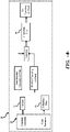
- the method 100 includes a first step 102 of determining at least one wind parameter at the wind turbine, e.g. a wind speed.
- a next step 104 includes monitoring an operating condition of the wind turbine, e.g. a fluctuating generator speed.
- the method 100 includes a step 106 of determining, by a processor, a variance of the monitored operating condition and of a plurality of the wind parameters, wherein the variance is indicative of an oscillation occurring in one or more wind turbine components.
- the method 100 includes determining, by a processor, an operating set point based on the variance (step 108).
- the method 100 also includes operating the wind turbine based on the operating set point when the variance indicates that the oscillation has a frequency within a certain frequency band so as to modify the frequency, wherein the modified frequency is outside of the frequency band and reduces oscillation loads occurring at the one or more wind turbine components induced by high turbulence intensity. (step 110).
Landscapes
- Engineering & Computer Science (AREA)
- Combustion & Propulsion (AREA)
- Chemical & Material Sciences (AREA)
- General Engineering & Computer Science (AREA)
- Mechanical Engineering (AREA)
- Life Sciences & Earth Sciences (AREA)
- Sustainable Development (AREA)
- Sustainable Energy (AREA)
- Physics & Mathematics (AREA)
- General Physics & Mathematics (AREA)
- Fluid Mechanics (AREA)
- Automation & Control Theory (AREA)
- Power Engineering (AREA)
- Wind Motors (AREA)
- Connection Of Motors, Electrical Generators, Mechanical Devices, And The Like (AREA)
Claims (13)
- Procédé (100) pour réduire les charges d'oscillation d'une turbine éolienne (10) induites par des turbulences élevées ou combinées avec d'autres conditions environnementales, le procédé comprenant :la détermination (102) d'au moins un paramètre de vent au niveau de la turbine éolienne (10) ; dans lequel la détermination (102) de l'au moins un paramètre de vent comprend le filtrage d'une pluralité de paramètres de vent ;la surveillance (104) d'une condition de fonctionnement de la turbine éolienne (10) ;la détermination (106), par un processeur (58), d'une variance (72) de la condition de fonctionnement surveillée en fonction au moins en partie de l'écarttype de la condition de fonctionnement, et de la pluralité des paramètres de vent, dans lequel la variance (72) est indicative d'une oscillation se produisant au niveau d'un ou plusieurs composants de turbine éolienne ;la détermination (108), par le processeur (58), d'un point de consigne de fonctionnement en fonction de la variance (72) ; etla mise en fonctionnement (110) de la turbine éolienne (10) en fonction du point de consigne de fonctionnement lorsque la variance (72) indique que l'oscillation comprend une fréquence dans une certaine bande de fréquences afin de modifier la fréquence, dans lequel la fréquence modifiée est en dehors de la bande de fréquences et réduit les charges d'oscillation se produisant au niveau de l'un ou plusieurs composants de turbine éolienne.
- Procédé (100) selon la revendication 1, dans lequel la bande de fréquences comprend l'une d'une bande de fréquences prédéterminée ou d'une bande de fréquences calculée.
- Procédé (100) selon une quelconque revendication précédente, dans lequel la bande de fréquences comprend une ou plusieurs fréquences de résonance de l'un ou plusieurs composants de turbine éolienne.
- Procédé (100) selon une quelconque revendication précédente, dans lequel les un ou plusieurs composants de turbine éolienne comprennent une pale de rotor (22) de la turbine éolienne (10), et dans lequel la variance (72) est indicative d'une oscillation de bord de pale ou d'une oscillation de volet de pale.
- Procédé (100) selon une quelconque revendication précédente, dans lequel l'au moins un paramètre de vent reflète l'un quelconque ou une combinaison de ce qui suit : une rafale de vent, une vitesse de vent, une direction de vent, une accélération de vent, une turbulence de vent, un cisaillement de vent, un tournoiement de vent, ou un sillage.
- Procédé (100) selon une quelconque revendication précédente, dans lequel l'étape de détermination de l'au moins un paramètre de vent au niveau de la turbine éolienne (10) comprend en outre au moins l'un de ce qui suit : l'utilisation d'un ou plusieurs capteurs (48, 50, 52) pour mesurer le paramètre de vent ou estimer le paramètre de vent, dans lequel l'estimation du paramètre de vent comprend l'un ou une combinaison de ce qui suit : une ou plusieurs conditions de fonctionnement de la turbine éolienne (10), une pluralité d'équations, une ou plusieurs cartes de performance aérodynamique, une ou plusieurs tables de consultation, ou un ou plusieurs paramètres adaptatifs de la turbine éolienne (10).
- Procédé (100) selon la revendication 1, dans lequel l'étape de filtrage de la pluralité de paramètres de vent comprend en outre l'utilisation de l'un ou d'une combinaison d'un filtre passe-bas, d'un filtre passe-haut, ou d'un filtre passebande.
- Procédé (100) selon une quelconque revendication précédente, dans lequel la condition de fonctionnement surveillée comprend l'un quelconque ou une combinaison de ce qui suit : un angle d'inclinaison, un générateur (24), une vitesse, une sortie de puissance, ou une sortie de couple.
- Procédé (100) selon une quelconque revendication précédente, comprenant en outre l'utilisation d'un filtre (70) pour stabiliser l'écart-type de la condition de fonctionnement surveillée.
- Procédé (100) selon une quelconque revendication précédente, dans lequel la détermination du point de consigne de fonctionnement (108) en fonction de la variance (72) comprend en outre la prise en compte de la capacité électrique de la turbine éolienne (10), dans lequel la capacité électrique de la turbine éolienne (10) est une fonction d'au moins une disponibilité de couple de la turbine éolienne (10).
- Procédé (100) selon une quelconque revendication précédente, comprenant en outre l'entrée du point de consigne de fonctionnement dans l'un d'un filtre ou d'une fonction S (70) pour stabiliser une transition vers le point de consigne de fonctionnement.
- Procédé (100) selon une quelconque revendication précédente, dans lequel l'étape (110) de mise en fonctionnement de la turbine éolienne (10) en fonction du point de consigne de fonctionnement comprend en outre au moins l'un parmi l'allègement ou l'augmentation du régime de la turbine éolienne (10), dans lequel l'allègement ou l'augmentation du régime de la turbine éolienne (10) comprend en outre la modification de l'un ou d'une combinaison d'une vitesse de générateur (24), une demande de couple, un angle d'inclinaison d'une pale de rotor (22), une sortie de puissance, une orientation d'une nacelle (16) de la turbine éolienne (10), un banc de charge, un mécanisme abaisseur-élévateur, ou l'actionnement d'un ou plusieurs éléments modificateurs du flux d'air.
- Système pour réduire les charges d'oscillation d'une turbine éolienne (10) induites par des turbulences élevées ou combinées avec d'autres conditions environnementales, le système comprenant :
un processeur (58) configuré pour :déterminer (102) au moins un paramètre de vent au niveau de la turbine éolienne (10), dans lequel la détermination (102) de l'au moins un paramètre de vent comprend le filtrage d'une pluralité de paramètres de vent ;surveiller (104) une condition de fonctionnement de la turbine éolienne (10) ;déterminer (106) une variance (72) de la condition de fonctionnement surveillée en fonction au moins en partie de l'écart-type de la condition de fonctionnement, et de la pluralité des paramètres de vent, dans lequel la variance (72) est indicative d'une oscillation se produisant au niveau d'un ou plusieurs composants de turbine éolienne ;déterminer (108) un point de consigne de fonctionnement en fonction de la variance (72) ; etun contrôleur (26) couplé de manière communicative au processeur (58), dans lequel le contrôleur (26) est configuré pour faire fonctionner la turbine éolienne (10) en fonction du point de consigne de fonctionnement lorsque la variance (72) indique que l'oscillation comprend une fréquence dans une certaine bande de fréquences afin de modifier la fréquence, dans lequel la fréquence modifiée est en dehors de la bande de fréquences et réduit les charges d'oscillation se produisant au niveau de l'un ou plusieurs composants de turbine éolienne.
Applications Claiming Priority (1)
| Application Number | Priority Date | Filing Date | Title |
|---|---|---|---|
| PCT/CN2013/088885 WO2015085465A1 (fr) | 2013-12-09 | 2013-12-09 | Système et procédé pour réduire des charges d'oscillation de turbine éolienne |
Publications (3)
| Publication Number | Publication Date |
|---|---|
| EP3080444A1 EP3080444A1 (fr) | 2016-10-19 |
| EP3080444A4 EP3080444A4 (fr) | 2017-08-09 |
| EP3080444B1 true EP3080444B1 (fr) | 2022-03-30 |
Family
ID=53370437
Family Applications (1)
| Application Number | Title | Priority Date | Filing Date |
|---|---|---|---|
| EP13898996.7A Active EP3080444B1 (fr) | 2013-12-09 | 2013-12-09 | Système et procédé pour réduire des charges d'oscillation de turbine éolienne |
Country Status (6)
| Country | Link |
|---|---|
| US (1) | US10107261B2 (fr) |
| EP (1) | EP3080444B1 (fr) |
| CA (1) | CA2931690C (fr) |
| DK (1) | DK3080444T3 (fr) |
| ES (1) | ES2920684T3 (fr) |
| WO (1) | WO2015085465A1 (fr) |
Families Citing this family (35)
| Publication number | Priority date | Publication date | Assignee | Title |
|---|---|---|---|---|
| EP3212927B1 (fr) | 2014-10-31 | 2021-02-24 | General Electric Company | Système et procédé pour commander le fonctionnement d'une éolienne |
| DK179069B1 (en) * | 2015-09-04 | 2017-10-02 | Envision Energy Denmark Aps | A wind turbine and a method of operating a wind turbine with a rotational speed exclusion zone |
| JP6559559B2 (ja) * | 2015-12-11 | 2019-08-14 | 株式会社日立製作所 | 風力発電システムおよび風力発電システムの運転方法 |
| EP3391497B1 (fr) * | 2015-12-17 | 2021-11-17 | Vestas Wind Systems A/S | Modulation de sortie de centrale éolienne à l'aide de différentes composantes de modulation de fréquence pour amortir des oscillations de réseau électrique |
| DE102015122039A1 (de) * | 2015-12-17 | 2017-06-22 | Wobben Properties Gmbh | Verfahren zum Steuern einer Windenergieanlage |
| CN105811407B (zh) * | 2016-04-18 | 2018-07-06 | 清华大学 | 一种基于分布式牛顿法的微电网一次调频控制方法 |
| US10451036B2 (en) | 2017-05-05 | 2019-10-22 | General Electric Company | Adjustment factor for aerodynamic performance map |
| US10570883B2 (en) * | 2017-12-22 | 2020-02-25 | General Electric Company | System and method for protecting wind turbines during wind gusts |
| CN109958574B (zh) * | 2017-12-22 | 2020-05-05 | 北京金风科创风电设备有限公司 | 用于风力发电机组的降载控制方法和装置 |
| DE102017131389B4 (de) * | 2017-12-28 | 2022-05-05 | fos4X GmbH | Verfahren zum Kalibrieren von Nominalfrequenzen |
| EP3505754A1 (fr) * | 2018-01-02 | 2019-07-03 | Siemens Gamesa Renewable Energy A/S | Détection d'un mouvement oscillant d'une éolienne |
| DE102018100727A1 (de) * | 2018-01-15 | 2019-07-18 | Wobben Properties Gmbh | Verfahren zum Steuern einer Windenergieanlage und Windenergieanlage |
| EP3749850B1 (fr) * | 2018-02-09 | 2022-11-30 | Vestas Wind Systems A/S | Procédé et système de commande d'une éolienne pour gérer les vibrations de pale dans le sens de la traînée |
| ES2947412T3 (es) * | 2018-05-31 | 2023-08-08 | Ge Renewable Tech Wind Bv | Métodos y sistemas para el funcionamiento una turbina eólica |
| US10823146B2 (en) * | 2018-06-14 | 2020-11-03 | General Electric Company | System and method for controlling a wind turbine to minimize rotor blade damage |
| DE102018124084A1 (de) * | 2018-09-28 | 2020-04-02 | Wobben Properties Gmbh | Verfahren zum Betreiben einer Windenergieanlage, Windenergieanlage und Windpark |
| US11635062B2 (en) | 2018-11-07 | 2023-04-25 | General Electric Renovables Espana, S.L. | Wind turbine and method to determine modal characteristics of the wind turbine in a continuous manner |
| EP3667076A1 (fr) | 2018-12-13 | 2020-06-17 | Siemens Gamesa Renewable Energy A/S | Estimation de la vitesse du vent |
| ES2937864T3 (es) * | 2019-04-03 | 2023-03-31 | Nordex Energy Se & Co Kg | Procedimiento para el funcionamiento de una instalación de energía eólica con al menos una pala de rotor de ángulo de paso de pala ajustable |
| EP3739203A1 (fr) * | 2019-05-16 | 2020-11-18 | Siemens Gamesa Renewable Energy A/S | Procédé et système pour détecter une rafale de vent affectant une éolienne |
| US20210047995A1 (en) * | 2019-08-15 | 2021-02-18 | Marinvent Corporation | Airfoil Performance Monitor |
| EP3795824A1 (fr) | 2019-09-18 | 2021-03-24 | General Electric Company | Système et procédé pour atténuer les vibrations de formation de vortex ou induites par décrochage sur une pale de rotor d'une éolienne pendant un arrêt |
| GB2590388B (en) * | 2019-12-13 | 2022-02-16 | Equinor Energy As | Blade pitch controller for a wind turbine |
| DE102020105053A1 (de) * | 2020-02-26 | 2021-08-26 | fos4X GmbH | Verfahren zur Zustandsüberwachung eines Antriebsstrangs oder Turms einer Windenergieanlage und Windenergieanlage |
| CN111412115A (zh) * | 2020-04-07 | 2020-07-14 | 国家电投集团广西电力有限公司 | 一种新型风电塔筒状态在线监测方法及系统 |
| CN113847197B (zh) | 2020-06-28 | 2023-02-28 | 北京金风科创风电设备有限公司 | 风力发电机组及其避转速控制方法、装置 |
| GB202010416D0 (en) | 2020-07-07 | 2020-08-19 | General Electric Renovables Espana Sl | Rotor blade assembly for mitigating stall induced vibrations |
| US11549493B2 (en) * | 2020-07-24 | 2023-01-10 | General Electric Company | System and method for frequency filtering of a renewable energy power system |
| NL2028217B1 (en) * | 2021-05-14 | 2022-11-30 | Univ Delft Tech | Enhanced wake mixing for floating wind turbines |
| JP7706946B2 (ja) * | 2021-06-15 | 2025-07-14 | 株式会社日立パワーソリューションズ | 再生可能エネルギー発電システムおよび再生可能エネルギー発電システムの制御方法 |
| US11639710B2 (en) * | 2021-06-25 | 2023-05-02 | WindESCo, Inc. | Systems and methods of coordinated yaw control of multiple wind turbines |
| EP4160006B1 (fr) * | 2021-10-01 | 2025-11-05 | Wobben Properties GmbH | Procédé de fonctionnement d'une éolienne |
| DK4160005T3 (da) * | 2021-10-01 | 2026-02-09 | Wobben Properties Gmbh | Fremgangsmåde til drift af en vindenergianlæg |
| CN116136206B (zh) * | 2023-03-23 | 2025-02-18 | 中国华能集团清洁能源技术研究院有限公司 | 风电机组的特征振荡频率预警方法及系统 |
| EP4621373A1 (fr) * | 2024-03-18 | 2025-09-24 | RTDT Laboratories AG | Procédé mis en uvre par ordinateur, produit de programme informatique, noeud de capteur, dispositif de capteur et système de surveillance de profil(s) aérodynamique(s) |
Family Cites Families (36)
| Publication number | Priority date | Publication date | Assignee | Title |
|---|---|---|---|---|
| DE19532409B4 (de) | 1995-09-01 | 2005-05-12 | Wobben, Aloys, Dipl.-Ing. | Verfahren zum Betreiben einer Windenergieanlage und eine zugehörige Windenergieanlage |
| DK58998A (da) | 1998-04-30 | 1999-10-31 | Lm Glasfiber As | Vindmølle |
| GB2398841A (en) | 2003-02-28 | 2004-09-01 | Qinetiq Ltd | Wind turbine control having a Lidar wind speed measurement apparatus |
| US7175389B2 (en) | 2004-06-30 | 2007-02-13 | General Electric Company | Methods and apparatus for reducing peak wind turbine loads |
| DE102004054608B4 (de) | 2004-09-21 | 2006-06-29 | Repower Systems Ag | Verfahren zur Regelung einer Windenergieanlage und Windenergieanlage mit einem Rotor |
| US7309930B2 (en) * | 2004-09-30 | 2007-12-18 | General Electric Company | Vibration damping system and method for variable speed wind turbines |
| US7822560B2 (en) | 2004-12-23 | 2010-10-26 | General Electric Company | Methods and apparatuses for wind turbine fatigue load measurement and assessment |
| DE102005029000B4 (de) | 2005-06-21 | 2007-04-12 | Repower Systems Ag | Verfahren und System zur Regelung der Drehzahl eines Rotors einer Windenergieanlage |
| US7476985B2 (en) | 2005-07-22 | 2009-01-13 | Gamesa Innovation & Technology, S.L. | Method of operating a wind turbine |
| US7342323B2 (en) | 2005-09-30 | 2008-03-11 | General Electric Company | System and method for upwind speed based control of a wind turbine |
| US20070114799A1 (en) * | 2005-11-18 | 2007-05-24 | Andre Riesberg | Systems and methods for damping a displacement of a wind turbine tower |
| US7613548B2 (en) | 2006-01-26 | 2009-11-03 | General Electric Company | Systems and methods for controlling a ramp rate of a wind farm |
| JP4814644B2 (ja) * | 2006-02-01 | 2011-11-16 | 富士重工業株式会社 | 風力発電装置 |
| US7505833B2 (en) | 2006-03-29 | 2009-03-17 | General Electric Company | System, method, and article of manufacture for controlling operation of an electrical power generation system |
| US7346462B2 (en) | 2006-03-29 | 2008-03-18 | General Electric Company | System, method, and article of manufacture for determining parameter values associated with an electrical grid |
| EP2035699B1 (fr) * | 2006-06-30 | 2018-08-08 | Vestas Wind Systems A/S | Tour d'éolienne et procédé pour modifier la fréquence propre d'une tour d'éolienne |
| US8021110B2 (en) * | 2007-01-05 | 2011-09-20 | General Electric Company | Tonal emission control for wind turbines |
| DK1988284T5 (da) | 2007-05-03 | 2019-09-30 | Siemens Gamesa Renewable Energy As | Fremgangsmåde til at drive en vindmølle og vindmølle |
| US7573149B2 (en) | 2007-12-06 | 2009-08-11 | General Electric Company | System and method for controlling a wind power plant |
| US7861583B2 (en) | 2008-01-17 | 2011-01-04 | General Electric Company | Wind turbine anemometry compensation |
| US7999406B2 (en) | 2008-02-29 | 2011-08-16 | General Electric Company | Wind turbine plant high wind derating control |
| US7942629B2 (en) | 2008-04-22 | 2011-05-17 | General Electric Company | Systems and methods involving wind turbine towers for power applications |
| CN101684774B (zh) | 2008-09-28 | 2012-12-26 | 通用电气公司 | 一种风力发电系统及风力发电机的测风方法 |
| US8128361B2 (en) | 2008-12-19 | 2012-03-06 | Frontier Wind, Llc | Control modes for extendable rotor blades |
| US8050887B2 (en) | 2008-12-22 | 2011-11-01 | General Electric Company | Method and system for determining a potential for icing on a wind turbine blade |
| US8025476B2 (en) * | 2009-09-30 | 2011-09-27 | General Electric Company | System and methods for controlling a wind turbine |
| US7772713B2 (en) | 2009-09-30 | 2010-08-10 | General Electric Company | Method and system for controlling a wind turbine |
| US8360723B2 (en) * | 2009-09-30 | 2013-01-29 | General Electric Company | Method for reducing vibrations in wind turbines and wind turbine implementing said method |
| GB2476507A (en) | 2009-12-23 | 2011-06-29 | Vestas Wind Sys As | Method And Apparatus For Protecting Wind Turbines From Gust Damage |
| US8123478B2 (en) * | 2010-05-26 | 2012-02-28 | General Electric Company | Systems and methods for monitoring a condition of a rotor blade for a wind turbine |
| US20110140425A1 (en) * | 2010-08-25 | 2011-06-16 | Martin Staedler | Method and System For Controlling Wind Turbine Rotational Speed |
| DE102010053523B4 (de) * | 2010-12-04 | 2015-09-10 | Nordex Energy Gmbh | Verfahren zur Überwachung einer statischen und/oder dynamischen Stabilität einer Windenergieanlage |
| US8169098B2 (en) * | 2010-12-22 | 2012-05-01 | General Electric Company | Wind turbine and operating same |
| EP2655876B1 (fr) | 2010-12-23 | 2016-08-17 | Vestas Wind Systems A/S | Supervision de l'instabilité du dispositif de commande dans une éolienne |
| JP5680526B2 (ja) * | 2011-12-28 | 2015-03-04 | 三菱重工業株式会社 | 風力発電用風車の衝撃荷重監視システム及び衝撃荷重監視方法 |
| EP2620639B1 (fr) * | 2012-01-30 | 2016-01-27 | ALSTOM Renewable Technologies | Procédé pour amortir les oscillations dans une éolienne |
-
2013
- 2013-12-09 WO PCT/CN2013/088885 patent/WO2015085465A1/fr not_active Ceased
- 2013-12-09 US US15/101,001 patent/US10107261B2/en active Active
- 2013-12-09 ES ES13898996T patent/ES2920684T3/es active Active
- 2013-12-09 EP EP13898996.7A patent/EP3080444B1/fr active Active
- 2013-12-09 DK DK13898996.7T patent/DK3080444T3/da active
- 2013-12-09 CA CA2931690A patent/CA2931690C/fr active Active
Also Published As
| Publication number | Publication date |
|---|---|
| ES2920684T3 (es) | 2022-08-08 |
| EP3080444A1 (fr) | 2016-10-19 |
| US20160305403A1 (en) | 2016-10-20 |
| DK3080444T3 (da) | 2022-06-13 |
| WO2015085465A1 (fr) | 2015-06-18 |
| EP3080444A4 (fr) | 2017-08-09 |
| CA2931690C (fr) | 2020-08-04 |
| CA2931690A1 (fr) | 2015-06-18 |
| US10107261B2 (en) | 2018-10-23 |
Similar Documents
| Publication | Publication Date | Title |
|---|---|---|
| EP3080444B1 (fr) | Système et procédé pour réduire des charges d'oscillation de turbine éolienne | |
| EP2860394B1 (fr) | Système et procédé permettant d'éviter une charge excessive sur une turbine éolienne | |
| EP3056726B1 (fr) | Système et procédé pour faire fonctionner une éolienne sur la base de la marge de pale de rotor | |
| EP2840258B1 (fr) | Système et procédé pour éviter un surchargement excessif d'une éolienne | |
| CN109312716B (zh) | 用于控制风力涡轮机以管理缘向叶片振动的方法和系统 | |
| EP3218600B1 (fr) | Système et procédé d'estimation de charges de pale de rotor d'une éolienne | |
| US9551321B2 (en) | System and method for controlling a wind turbine | |
| EP2910777B1 (fr) | Vitesse dynamique de vent minimum de démarrage pour éoliennes | |
| EP3892851B1 (fr) | Système et procédé de commande sous charge extrême améliorée pour pales de rotor d'éolienne | |
| US9926912B2 (en) | System and method for estimating wind coherence and controlling wind turbine based on same | |
| EP2981710B1 (fr) | Procédé de régulation de poussée axiale pour une éolienne | |
| EP3631200B1 (fr) | Système et procédé d'optimisation de la puissance de sortie d'une éolienne pendant une contrainte opérationnelle | |
| EP3643914B1 (fr) | Système et procédé pour protéger des éoliennes contre les charges extrêmes et de fatigue | |
| CN111512043A (zh) | 用于控制风力涡轮机以管理边缘叶片振动的方法和系统 | |
| KR20230129930A (ko) | 풍력 터빈에서의 진동 | |
| EP3961845B1 (fr) | Système et procédé de gestion de scintillement de sortie généré par un parc éolien |
Legal Events
| Date | Code | Title | Description |
|---|---|---|---|
| PUAI | Public reference made under article 153(3) epc to a published international application that has entered the european phase |
Free format text: ORIGINAL CODE: 0009012 |
|
| 17P | Request for examination filed |
Effective date: 20160711 |
|
| AK | Designated contracting states |
Kind code of ref document: A1 Designated state(s): AL AT BE BG CH CY CZ DE DK EE ES FI FR GB GR HR HU IE IS IT LI LT LU LV MC MK MT NL NO PL PT RO RS SE SI SK SM TR |
|
| AX | Request for extension of the european patent |
Extension state: BA ME |
|
| DAX | Request for extension of the european patent (deleted) | ||
| A4 | Supplementary search report drawn up and despatched |
Effective date: 20170706 |
|
| RIC1 | Information provided on ipc code assigned before grant |
Ipc: F03D 7/04 20060101ALI20170630BHEP Ipc: F03D 7/02 20060101AFI20170630BHEP |
|
| STAA | Information on the status of an ep patent application or granted ep patent |
Free format text: STATUS: EXAMINATION IS IN PROGRESS |
|
| 17Q | First examination report despatched |
Effective date: 20190711 |
|
| GRAP | Despatch of communication of intention to grant a patent |
Free format text: ORIGINAL CODE: EPIDOSNIGR1 |
|
| STAA | Information on the status of an ep patent application or granted ep patent |
Free format text: STATUS: GRANT OF PATENT IS INTENDED |
|
| RIC1 | Information provided on ipc code assigned before grant |
Ipc: F03D 7/02 20060101AFI20210602BHEP Ipc: F03D 7/04 20060101ALI20210602BHEP Ipc: F03D 17/00 20160101ALI20210602BHEP |
|
| INTG | Intention to grant announced |
Effective date: 20210622 |
|
| GRAJ | Information related to disapproval of communication of intention to grant by the applicant or resumption of examination proceedings by the epo deleted |
Free format text: ORIGINAL CODE: EPIDOSDIGR1 |
|
| STAA | Information on the status of an ep patent application or granted ep patent |
Free format text: STATUS: EXAMINATION IS IN PROGRESS |
|
| GRAP | Despatch of communication of intention to grant a patent |
Free format text: ORIGINAL CODE: EPIDOSNIGR1 |
|
| STAA | Information on the status of an ep patent application or granted ep patent |
Free format text: STATUS: GRANT OF PATENT IS INTENDED |
|
| INTC | Intention to grant announced (deleted) | ||
| INTG | Intention to grant announced |
Effective date: 20211116 |
|
| GRAS | Grant fee paid |
Free format text: ORIGINAL CODE: EPIDOSNIGR3 |
|
| GRAA | (expected) grant |
Free format text: ORIGINAL CODE: 0009210 |
|
| STAA | Information on the status of an ep patent application or granted ep patent |
Free format text: STATUS: THE PATENT HAS BEEN GRANTED |
|
| AK | Designated contracting states |
Kind code of ref document: B1 Designated state(s): AL AT BE BG CH CY CZ DE DK EE ES FI FR GB GR HR HU IE IS IT LI LT LU LV MC MK MT NL NO PL PT RO RS SE SI SK SM TR |
|
| REG | Reference to a national code |
Ref country code: GB Ref legal event code: FG4D |
|
| REG | Reference to a national code |
Ref country code: CH Ref legal event code: EP |
|
| REG | Reference to a national code |
Ref country code: AT Ref legal event code: REF Ref document number: 1479414 Country of ref document: AT Kind code of ref document: T Effective date: 20220415 |
|
| REG | Reference to a national code |
Ref country code: DE Ref legal event code: R096 Ref document number: 602013081282 Country of ref document: DE |
|
| REG | Reference to a national code |
Ref country code: IE Ref legal event code: FG4D |
|
| REG | Reference to a national code |
Ref country code: DK Ref legal event code: T3 Effective date: 20220608 |
|
| REG | Reference to a national code |
Ref country code: LT Ref legal event code: MG9D |
|
| PG25 | Lapsed in a contracting state [announced via postgrant information from national office to epo] |
Ref country code: SE Free format text: LAPSE BECAUSE OF FAILURE TO SUBMIT A TRANSLATION OF THE DESCRIPTION OR TO PAY THE FEE WITHIN THE PRESCRIBED TIME-LIMIT Effective date: 20220330 Ref country code: RS Free format text: LAPSE BECAUSE OF FAILURE TO SUBMIT A TRANSLATION OF THE DESCRIPTION OR TO PAY THE FEE WITHIN THE PRESCRIBED TIME-LIMIT Effective date: 20220330 Ref country code: NO Free format text: LAPSE BECAUSE OF FAILURE TO SUBMIT A TRANSLATION OF THE DESCRIPTION OR TO PAY THE FEE WITHIN THE PRESCRIBED TIME-LIMIT Effective date: 20220630 Ref country code: LT Free format text: LAPSE BECAUSE OF FAILURE TO SUBMIT A TRANSLATION OF THE DESCRIPTION OR TO PAY THE FEE WITHIN THE PRESCRIBED TIME-LIMIT Effective date: 20220330 Ref country code: HR Free format text: LAPSE BECAUSE OF FAILURE TO SUBMIT A TRANSLATION OF THE DESCRIPTION OR TO PAY THE FEE WITHIN THE PRESCRIBED TIME-LIMIT Effective date: 20220330 Ref country code: BG Free format text: LAPSE BECAUSE OF FAILURE TO SUBMIT A TRANSLATION OF THE DESCRIPTION OR TO PAY THE FEE WITHIN THE PRESCRIBED TIME-LIMIT Effective date: 20220630 |
|
| REG | Reference to a national code |
Ref country code: NL Ref legal event code: MP Effective date: 20220330 |
|
| REG | Reference to a national code |
Ref country code: ES Ref legal event code: FG2A Ref document number: 2920684 Country of ref document: ES Kind code of ref document: T3 Effective date: 20220808 |
|
| REG | Reference to a national code |
Ref country code: AT Ref legal event code: MK05 Ref document number: 1479414 Country of ref document: AT Kind code of ref document: T Effective date: 20220330 |
|
| PG25 | Lapsed in a contracting state [announced via postgrant information from national office to epo] |
Ref country code: LV Free format text: LAPSE BECAUSE OF FAILURE TO SUBMIT A TRANSLATION OF THE DESCRIPTION OR TO PAY THE FEE WITHIN THE PRESCRIBED TIME-LIMIT Effective date: 20220330 Ref country code: GR Free format text: LAPSE BECAUSE OF FAILURE TO SUBMIT A TRANSLATION OF THE DESCRIPTION OR TO PAY THE FEE WITHIN THE PRESCRIBED TIME-LIMIT Effective date: 20220701 Ref country code: FI Free format text: LAPSE BECAUSE OF FAILURE TO SUBMIT A TRANSLATION OF THE DESCRIPTION OR TO PAY THE FEE WITHIN THE PRESCRIBED TIME-LIMIT Effective date: 20220330 |
|
| PG25 | Lapsed in a contracting state [announced via postgrant information from national office to epo] |
Ref country code: NL Free format text: LAPSE BECAUSE OF FAILURE TO SUBMIT A TRANSLATION OF THE DESCRIPTION OR TO PAY THE FEE WITHIN THE PRESCRIBED TIME-LIMIT Effective date: 20220330 |
|
| PG25 | Lapsed in a contracting state [announced via postgrant information from national office to epo] |
Ref country code: SM Free format text: LAPSE BECAUSE OF FAILURE TO SUBMIT A TRANSLATION OF THE DESCRIPTION OR TO PAY THE FEE WITHIN THE PRESCRIBED TIME-LIMIT Effective date: 20220330 Ref country code: SK Free format text: LAPSE BECAUSE OF FAILURE TO SUBMIT A TRANSLATION OF THE DESCRIPTION OR TO PAY THE FEE WITHIN THE PRESCRIBED TIME-LIMIT Effective date: 20220330 Ref country code: RO Free format text: LAPSE BECAUSE OF FAILURE TO SUBMIT A TRANSLATION OF THE DESCRIPTION OR TO PAY THE FEE WITHIN THE PRESCRIBED TIME-LIMIT Effective date: 20220330 Ref country code: PT Free format text: LAPSE BECAUSE OF FAILURE TO SUBMIT A TRANSLATION OF THE DESCRIPTION OR TO PAY THE FEE WITHIN THE PRESCRIBED TIME-LIMIT Effective date: 20220801 Ref country code: EE Free format text: LAPSE BECAUSE OF FAILURE TO SUBMIT A TRANSLATION OF THE DESCRIPTION OR TO PAY THE FEE WITHIN THE PRESCRIBED TIME-LIMIT Effective date: 20220330 Ref country code: CZ Free format text: LAPSE BECAUSE OF FAILURE TO SUBMIT A TRANSLATION OF THE DESCRIPTION OR TO PAY THE FEE WITHIN THE PRESCRIBED TIME-LIMIT Effective date: 20220330 Ref country code: AT Free format text: LAPSE BECAUSE OF FAILURE TO SUBMIT A TRANSLATION OF THE DESCRIPTION OR TO PAY THE FEE WITHIN THE PRESCRIBED TIME-LIMIT Effective date: 20220330 |
|
| PG25 | Lapsed in a contracting state [announced via postgrant information from national office to epo] |
Ref country code: PL Free format text: LAPSE BECAUSE OF FAILURE TO SUBMIT A TRANSLATION OF THE DESCRIPTION OR TO PAY THE FEE WITHIN THE PRESCRIBED TIME-LIMIT Effective date: 20220330 Ref country code: IS Free format text: LAPSE BECAUSE OF FAILURE TO SUBMIT A TRANSLATION OF THE DESCRIPTION OR TO PAY THE FEE WITHIN THE PRESCRIBED TIME-LIMIT Effective date: 20220730 Ref country code: AL Free format text: LAPSE BECAUSE OF FAILURE TO SUBMIT A TRANSLATION OF THE DESCRIPTION OR TO PAY THE FEE WITHIN THE PRESCRIBED TIME-LIMIT Effective date: 20220330 |
|
| REG | Reference to a national code |
Ref country code: DE Ref legal event code: R097 Ref document number: 602013081282 Country of ref document: DE |
|
| PLBE | No opposition filed within time limit |
Free format text: ORIGINAL CODE: 0009261 |
|
| STAA | Information on the status of an ep patent application or granted ep patent |
Free format text: STATUS: NO OPPOSITION FILED WITHIN TIME LIMIT |
|
| 26N | No opposition filed |
Effective date: 20230103 |
|
| PG25 | Lapsed in a contracting state [announced via postgrant information from national office to epo] |
Ref country code: SI Free format text: LAPSE BECAUSE OF FAILURE TO SUBMIT A TRANSLATION OF THE DESCRIPTION OR TO PAY THE FEE WITHIN THE PRESCRIBED TIME-LIMIT Effective date: 20220330 |
|
| P01 | Opt-out of the competence of the unified patent court (upc) registered |
Effective date: 20230530 |
|
| PG25 | Lapsed in a contracting state [announced via postgrant information from national office to epo] |
Ref country code: IT Free format text: LAPSE BECAUSE OF FAILURE TO SUBMIT A TRANSLATION OF THE DESCRIPTION OR TO PAY THE FEE WITHIN THE PRESCRIBED TIME-LIMIT Effective date: 20220330 |
|
| REG | Reference to a national code |
Ref country code: CH Ref legal event code: PL |
|
| GBPC | Gb: european patent ceased through non-payment of renewal fee |
Effective date: 20221209 |
|
| REG | Reference to a national code |
Ref country code: BE Ref legal event code: MM Effective date: 20221231 |
|
| PG25 | Lapsed in a contracting state [announced via postgrant information from national office to epo] |
Ref country code: LU Free format text: LAPSE BECAUSE OF NON-PAYMENT OF DUE FEES Effective date: 20221209 |
|
| PG25 | Lapsed in a contracting state [announced via postgrant information from national office to epo] |
Ref country code: LI Free format text: LAPSE BECAUSE OF NON-PAYMENT OF DUE FEES Effective date: 20221231 Ref country code: IE Free format text: LAPSE BECAUSE OF NON-PAYMENT OF DUE FEES Effective date: 20221209 Ref country code: GB Free format text: LAPSE BECAUSE OF NON-PAYMENT OF DUE FEES Effective date: 20221209 Ref country code: CH Free format text: LAPSE BECAUSE OF NON-PAYMENT OF DUE FEES Effective date: 20221231 |
|
| PG25 | Lapsed in a contracting state [announced via postgrant information from national office to epo] |
Ref country code: FR Free format text: LAPSE BECAUSE OF NON-PAYMENT OF DUE FEES Effective date: 20221231 Ref country code: BE Free format text: LAPSE BECAUSE OF NON-PAYMENT OF DUE FEES Effective date: 20221231 |
|
| REG | Reference to a national code |
Ref country code: DE Ref legal event code: R081 Ref document number: 602013081282 Country of ref document: DE Owner name: GENERAL ELECTRIC RENOVABLES ESPANA, S.L., ES Free format text: FORMER OWNER: GENERAL ELECTRIC COMPANY, SCHENECTADY, NY, US Ref country code: DE Ref legal event code: R082 Ref document number: 602013081282 Country of ref document: DE Ref country code: DE Ref legal event code: R082 Ref document number: 602013081282 Country of ref document: DE Representative=s name: ZIMMERMANN & PARTNER PATENTANWAELTE MBB, DE |
|
| REG | Reference to a national code |
Ref country code: DE Ref legal event code: R082 Ref document number: 602013081282 Country of ref document: DE Representative=s name: ZIMMERMANN & PARTNER PATENTANWAELTE MBB, DE |
|
| PG25 | Lapsed in a contracting state [announced via postgrant information from national office to epo] |
Ref country code: HU Free format text: LAPSE BECAUSE OF FAILURE TO SUBMIT A TRANSLATION OF THE DESCRIPTION OR TO PAY THE FEE WITHIN THE PRESCRIBED TIME-LIMIT; INVALID AB INITIO Effective date: 20131209 |
|
| PG25 | Lapsed in a contracting state [announced via postgrant information from national office to epo] |
Ref country code: CY Free format text: LAPSE BECAUSE OF FAILURE TO SUBMIT A TRANSLATION OF THE DESCRIPTION OR TO PAY THE FEE WITHIN THE PRESCRIBED TIME-LIMIT Effective date: 20220330 |
|
| PG25 | Lapsed in a contracting state [announced via postgrant information from national office to epo] |
Ref country code: MK Free format text: LAPSE BECAUSE OF FAILURE TO SUBMIT A TRANSLATION OF THE DESCRIPTION OR TO PAY THE FEE WITHIN THE PRESCRIBED TIME-LIMIT Effective date: 20220330 |
|
| PG25 | Lapsed in a contracting state [announced via postgrant information from national office to epo] |
Ref country code: MC Free format text: LAPSE BECAUSE OF FAILURE TO SUBMIT A TRANSLATION OF THE DESCRIPTION OR TO PAY THE FEE WITHIN THE PRESCRIBED TIME-LIMIT Effective date: 20220330 |
|
| PG25 | Lapsed in a contracting state [announced via postgrant information from national office to epo] |
Ref country code: TR Free format text: LAPSE BECAUSE OF FAILURE TO SUBMIT A TRANSLATION OF THE DESCRIPTION OR TO PAY THE FEE WITHIN THE PRESCRIBED TIME-LIMIT Effective date: 20220330 Ref country code: MC Free format text: LAPSE BECAUSE OF FAILURE TO SUBMIT A TRANSLATION OF THE DESCRIPTION OR TO PAY THE FEE WITHIN THE PRESCRIBED TIME-LIMIT Effective date: 20220330 |
|
| REG | Reference to a national code |
Ref country code: ES Ref legal event code: PC2A Owner name: GENERAL ELECTRIC RENOVABLES ESPANA S.L. Effective date: 20240809 |
|
| PG25 | Lapsed in a contracting state [announced via postgrant information from national office to epo] |
Ref country code: MT Free format text: LAPSE BECAUSE OF FAILURE TO SUBMIT A TRANSLATION OF THE DESCRIPTION OR TO PAY THE FEE WITHIN THE PRESCRIBED TIME-LIMIT Effective date: 20220330 |
|
| PGFP | Annual fee paid to national office [announced via postgrant information from national office to epo] |
Ref country code: DE Payment date: 20251126 Year of fee payment: 13 |
|
| PGFP | Annual fee paid to national office [announced via postgrant information from national office to epo] |
Ref country code: DK Payment date: 20251119 Year of fee payment: 13 |
|
| PGFP | Annual fee paid to national office [announced via postgrant information from national office to epo] |
Ref country code: ES Payment date: 20260102 Year of fee payment: 13 |