EP3080490B1 - Presse-garniture à anneau d'étanchéité unique - Google Patents
Presse-garniture à anneau d'étanchéité unique Download PDFInfo
- Publication number
- EP3080490B1 EP3080490B1 EP13811414.5A EP13811414A EP3080490B1 EP 3080490 B1 EP3080490 B1 EP 3080490B1 EP 13811414 A EP13811414 A EP 13811414A EP 3080490 B1 EP3080490 B1 EP 3080490B1
- Authority
- EP
- European Patent Office
- Prior art keywords
- ring
- seal
- rings
- sealing
- cover
- Prior art date
- Legal status (The legal status is an assumption and is not a legal conclusion. Google has not performed a legal analysis and makes no representation as to the accuracy of the status listed.)
- Active
Links
Images


Classifications
-
- F—MECHANICAL ENGINEERING; LIGHTING; HEATING; WEAPONS; BLASTING
- F16—ENGINEERING ELEMENTS AND UNITS; GENERAL MEASURES FOR PRODUCING AND MAINTAINING EFFECTIVE FUNCTIONING OF MACHINES OR INSTALLATIONS; THERMAL INSULATION IN GENERAL
- F16J—PISTONS; CYLINDERS; SEALINGS
- F16J15/00—Sealings
- F16J15/16—Sealings between relatively-moving surfaces
- F16J15/26—Sealings between relatively-moving surfaces with stuffing-boxes for rigid sealing rings
-
- F—MECHANICAL ENGINEERING; LIGHTING; HEATING; WEAPONS; BLASTING
- F04—POSITIVE - DISPLACEMENT MACHINES FOR LIQUIDS; PUMPS FOR LIQUIDS OR ELASTIC FLUIDS
- F04B—POSITIVE-DISPLACEMENT MACHINES FOR LIQUIDS; PUMPS
- F04B39/00—Component parts, details, or accessories, of pumps or pumping systems specially adapted for elastic fluids, not otherwise provided for in, or of interest apart from, groups F04B25/00 - F04B37/00
- F04B39/04—Measures to avoid lubricant contaminating the pumped fluid
- F04B39/041—Measures to avoid lubricant contaminating the pumped fluid sealing for a reciprocating rod
-
- F—MECHANICAL ENGINEERING; LIGHTING; HEATING; WEAPONS; BLASTING
- F16—ENGINEERING ELEMENTS AND UNITS; GENERAL MEASURES FOR PRODUCING AND MAINTAINING EFFECTIVE FUNCTIONING OF MACHINES OR INSTALLATIONS; THERMAL INSULATION IN GENERAL
- F16J—PISTONS; CYLINDERS; SEALINGS
- F16J15/00—Sealings
- F16J15/002—Sealings comprising at least two sealings in succession
-
- F—MECHANICAL ENGINEERING; LIGHTING; HEATING; WEAPONS; BLASTING
- F16—ENGINEERING ELEMENTS AND UNITS; GENERAL MEASURES FOR PRODUCING AND MAINTAINING EFFECTIVE FUNCTIONING OF MACHINES OR INSTALLATIONS; THERMAL INSULATION IN GENERAL
- F16J—PISTONS; CYLINDERS; SEALINGS
- F16J15/00—Sealings
- F16J15/46—Sealings with packing ring expanded or pressed into place by fluid pressure, e.g. inflatable packings
-
- Y—GENERAL TAGGING OF NEW TECHNOLOGICAL DEVELOPMENTS; GENERAL TAGGING OF CROSS-SECTIONAL TECHNOLOGIES SPANNING OVER SEVERAL SECTIONS OF THE IPC; TECHNICAL SUBJECTS COVERED BY FORMER USPC CROSS-REFERENCE ART COLLECTIONS [XRACs] AND DIGESTS
- Y10—TECHNICAL SUBJECTS COVERED BY FORMER USPC
- Y10S—TECHNICAL SUBJECTS COVERED BY FORMER USPC CROSS-REFERENCE ART COLLECTIONS [XRACs] AND DIGESTS
- Y10S277/00—Seal for a joint or juncture
- Y10S277/915—Seal including compression set feature
Definitions
- Embodiments of the invention generally relate to sealing arrangements for gas compressors, and more particularly to a stuffing box seal arrangement for a reciprocating gas compressor.
- a stuffing box is a sealing assembly that seals the area around the piston rod in a reciprocating compressor to minimize leakage of process gas from the compressor's pressurized cylinder to the atmosphere and/or the compressor's internal spaces.
- internal components of the stuffing box can experience high friction wear over time.
- the individual sealing elements used to seal against the piston rod surface can suffer from a short working life due to the frictional heat and frictional wear generated between the outer surface of the piston rod and the inner seal surface.
- the short life of these sealing elements results in relatively short maintenance intervals for the associated compressor. The more frequently the compressor must be taken off line to replace the sealing elements, the less efficient is the operation of the overall system.
- seals have been manufactured from Polytetrafluorethylene (PTFE) or Polyether ether - ketone (PEEK) materials combined with fillers such as carbon, graphite, Molybdenum disulfide (MoS 2 ) glass fiber, and the like.
- PTFE Polytetrafluorethylene
- PEEK Polyether ether - ketone
- fillers such as carbon, graphite, Molybdenum disulfide (MoS 2 ) glass fiber, and the like.
- Other attempts have involved the use of multiple sealing rings and pressure breaker rings in the stuffing box and/or applying pressure compensation techniques to limit wear.
- a stuffing box sealing arrangement is disclosed that is more resistant to operational wear than currently available sealing assemblies, particularly in high pressure and non-lubricated conditions.
- the disclosed design includes two parts. First, pressure compensation is employed to reduce the radial force on the seal rings. Second, novel wear resistant seal ring linings are provided. Lower radial force on the seal rings (due to pressure compensation) directly leads to less friction and, hence, to less wear and heat generation. In addition the improved seal ring lining design decreases gas leakage due to the high conformability of the thin (in radial direction) seal rings.
- the material used for the seal linings has a reduced friction coefficient which reduces friction wear even further.
- the seal material can also withstand high internal loads caused by pressure compensation at high pressures (e.g. >100 bar). Further, the material has a high resistance to contamination by particles.
- Conventional stuffing boxes generally consist of multiple pockets containing multiple rings and frequently demands lubrication to reduce wear.
- the disclosed seal ring design efficiently seals off piston rods in non-lubricated service and/or for high pressure conditions (>100bar). This results in a compact design of the overall stuffing box.
- the disclosed design may include a pressure compensation feature that includes grooves in the individual sealing rings. These grooves may be connected to the high pressure side of the stuffing box through a split in the support ring portion of the sealing ring.
- a cover seal ring may comprise conventional PTFE material, while the lining seal rings may be made from an improved friction resistant material comprising PEEK with nano-material additives for reduced friction and increased thermal conductivity.
- These lining seal rings have a high strength so that the ring set can be used at very high pressures. Due to this high mechanical strength, of the lining seal rings, the width of the rings can be small which, in combination with the pressure compensation feature, can result in low frictional power during operation.
- the disclosed use of lining seal rings in combination with one or more cover seal rings is an improvement over prior designs. While prior attempted solutions have employed pressure compensation, such attempts enabled only partial pressure compensation and used multiple split rings without lining seal rings.
- the disclosed combination of pressure compensation and low-friction lining seal rings can result in a sealing assembly that has a single ring configuration in lieu of prior multiple seal ring sets.
- the resulting stuffing box may have improved life compared to conventional seals and may be able to operate in high pressure and non-lubricated circumstances.
- the disclosed stuffing box will have a long life time, compact design and excellent performance under difficult circumstances, with less total seal material required.
- the disclosed design will ultimately lead to longer maintenance intervals for the compressors in which the sealing arrangement is employed.
- a sealing ring for use in a stuffing box of a reciprocating compressor.
- the sealing ring may include first and second seal rings engaged along respective side surfaces, and first and second cover rings disposed around the first and second seal rings such that the outside diameters of the first and second seal rings engage the inside diameters of the first and second cover rings, respectively.
- a support ring may be engaged with the first seal ring and the first cover ring, while a backup ring may be engaged with the second seal ring and the second cover ring.
- the first seal ring has a width that is smaller than a width of the second seal ring.
- the second seal ring has a circumferential groove formed on an inside surface thereof, the groove disposed directly adjacent the first seal ring.
- the first and second seal rings may be made from PEEK with a nano-material additive.
- a sealing ring for use in a stuffing box of a reciprocating compressor.
- the sealing ring may include first and second seal rings engaged with each other, and first and second cover rings disposed around the first and second seal rings.
- a support ring may be engaged with the first seal ring and the first cover ring, and a backup ring may be engaged with the second seal ring and the second cover ring.
- the first seal ring has a width that is smaller than a width of the second seal ring.
- the second seal ring has a groove formed on an inside surface thereof.
- the first and second seal rings may be made from PEEK with a nano-material additive.
- An improved sealing arrangement for use in reciprocating piston compressors.
- the improved sealing arrangement includes a multi-piece seal ring configured to undergo reduced wear in operation.
- the disclosed multi-piece seal ring design enables the associated reciprocating compressor to operate for longer periods between component refurbishment as compared to prior designs.
- the disclosed design also accommodates a wider range of differential operating pressures (suction vs. discharge) in non-lubricated applications as compared to prior devices.
- the compressor may include a frame 2, in which a cylinder 4 is disposed.
- the cylinder 4 contains a piston 6, which reciprocable in the cylinder 4.
- a piston rod 8 is fixed to the piston 6 at one end, and a crosshead 10 at the opposite end.
- the crosshead 10 is guided reciprocably in a horizontal straight line in the frame 2 of the compressor by means of a crosshead guide 12.
- the linear movement of the crosshead 10 is produced by a crank 14 which is coupled to the crosshead 10 via a connecting rod 16.
- the rotary movement of the crank 14 is transmitted to the crosshead 10 by the connecting rod 16.
- the illustrated compressor is of the double acting type, in which first and second compression chambers 20 and 22 are formed in the cylinder 4 on either side of the piston 6.
- Each of the first and second compression chambers 20, 22 is provided with appropriate suction and discharge valves such that movement of the piston 6 in the direction of the crank mechanism (i.e., to the left in FIG. 1 ), gas at a suction pressure is introduced into the second compression chamber 22 via the associated suction valve.
- gas present in the first compression chamber 20 is compressed and discharged at a discharge pressure via the associated discharge valve.
- a source of gas is coupled to the inlet valves, while the outlet valves may be coupled to appropriate discharge piping.
- a stuffing box 24 (see FIG. 7 ) is disposed about the piston rod 6 directly adjacent to the first compression chamber.
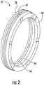
- the stuffing box 24 may include, inter alia, a plurality of sealing rings 25 (see FIG. 2 ) configured to prevent leakage of compressed gas from the first compression chamber 22.
- the stuffing box 24 comprises a cylindrical body portion 26 and a connecting flange portion 28. The cylindrical body portion 26 is slidably received within a correspondingly sized cylindrical recess 30 in the frame 2, while the connecting flange portion 28 abuts a sealing face 32 of the frame.
- the connecting flange portion 28 can be fixed to the frame 2 via a plurality of fasteners 34, which in the illustrated embodiment comprise bolts.
- fasteners 34 which in the illustrated embodiment comprise bolts.
- an appropriate gasket or other seal material can be disposed between the connecting flange portion 28 and the sealing face 32 of the flange.
- FIGS. 2-4B show an exemplary sealing ring 25 for use in the disclosed stuffing box 24 for sealing against the piston rod 6.
- the sealing ring 25 may be composed of a plurality of individual elements which together act to provide desired sealing characteristics during operation of the associated compressor 1.
- the illustrated sealing ring 25 includes a back-up ring 36 and a support ring 38 which together sandwich first and second cover rings 40, 42 and first and second seal rings 44, 46.
- the support ring 38 may be positioned on the side of the sealing set 25 subject to the high pressure of the first compression chamber 20. In operation the support ring 38 serves to keep the first and second seal rings 44, 46 and first and second cover rings 40, 42 in position relative to each other, and to prevent the first and second seal rings from slipping between the piston rod 6 and the stuffing box chamber.
- the support ring 38 may be a generally cylindrical flat ring member having an inside diameter ID1, and outside diameter OD1, first and second opposing faces 38a, b and a width W1.
- the support ring 38 may be made from PTFE so as to fill in any gaps in the portion of the stuffing box chamber that the back-up ring seals against.
- the support ring 38 may be positioned on the side of the sealing set 25 that faces the first compression chamber 20, and thus, it may be subjected to the pressure of the first compression chamber during operation.
- the support ring 38 is made from PTFE.
- the back-up ring 36 may likewise be a generally cylindrical ring flat member having an inside diameter ID2, an outside diameter OD2, first and second opposing faces 36a, b and a width W2.
- the back-up ring 36 is made from metal such as bronze or Cast Iron, to prevent extrusion of the first and second seal rings 44, 46 when the sealing set 25 is under pressure.
- the first and second cover rings 40, 42 may be cylindrical ring members each having an inside diameter ID3, ID4 an outside diameter OD3, OD4, first and second opposing faces 40a, b, 42a, b and a width W3, W4.
- the first cover ring 40 can have a width W3 that is smaller than the width W4 of the second cover ring 42. This relative width arrangement is part of the pressure compensation function of the sealing ring 25 design, as will be described in greater detail later.
- the first and second cover rings 40, 42 can include respective first and second outer circumferential recesses 41, 43 configured to receive respective first and second spring elements 45, 47 for maintaining the first and second cover rings 40, 42 engaged with the first and second sealing rings 44, 46.
- the first and second seal rings 44, 46 may be cylindrical ring members each having an inside diameter ID5, ID6, an outside diameter OD5, OD6, first and second opposing faces 44a, b, 46a, b and a width W5, W6.
- ID5, ID6 of each of the first and second seal rings 44, 46 is smaller than the inside diameter ID3, ID4 of the first and second cover rings 40, 42 so that the first and second seal rings can be enclosed by the first and second cover rings with the sealing ring 25 is assembled.
- first and second seal rings 44, 46 may further each include a radially extending tab 49, 51 configured to fit within a respective radial recess 53, 55 formed in the associated cover rings 40, 42 to prevent relative rotation of the first and second seal rings during operation.
- first and second seal rings 44, 46 have inside diameters ID5, ID6 that are substantially equal and outside diameters OD5, OD6 that are substantially equal.
- the second seal ring 46 has a width W6 that is greater than the width W5 of the first seal ring 44.
- the widths W5, W6 of the first and second seal rings 44, 46 may correspond to the widths W3, W4 of their respective cover ring 40, 42.
- the first and second seal rings 44, 46 may further be "split" rings in that they may each have an opening 57, 59 that allows them to expand or contract slightly to accommodate small differences in piston rod diameter, thus ensuring constant contact with the piston rod 6.
- the openings 57, 59 in the first and second seal rings 44, 46 are offset from each other so as not to constitute a leak path through the sealing ring 25.
- the openings 57, 59 are offset by about 180-degrees, though this is not critical and offsets of other magnitudes can be used.
- the first and second cover rings 40, 42 may function as "split" rings, owing to the radial recesses 53, 55 formed therein. These recesses can allow the first and second cover rings 40, 42 to expand or contract slightly to match any small adjustments in the outside diameter OD5, OD6 of the associated first or second seal ring 44, 46 during operation.
- the first cover ring 40 includes a second recess 57 spaced about 180-degrees apart from the recess 53. Referring to FIG. 3B , this second recess 57 receives a projection 61 formed on the second cover ring 42. This inter-fitting prevents rotation of the rings with respect to each other. It will be appreciated that this projection/recess arrangement is not critical, and that other features may be used to prevent relative rotation between the elements.
- the close inter-fitting arrangement of the elements of the seal ring set 25 can be seen in FIG. 4B , in which the first and second seal rings 44, 46 are covered about their outside diameters OD5, OD6 by respective inside diameters ID3, ID4 of the first and second cover rings 40, 42.
- This group of elements is then sandwiched between the support ring 38 and back-up ring 36.
- the axial clearance of the complete seal ring set 25 in the chamber may be adjusted by adjusting the width W1 of the support ring 38.
- the clearance between individual elements of the seal ring set 25 is small enough to maintain the elements of the seal ring set together, while being large enough to accommodate the thermal expansion of the elements during operation.
- the first and second spring elements 45, 47 maintain the first and second cover rings 40, 42 together and engaged around the first and second seal rings 44,46.
- FIG. 5A shows an alternative construction of a sealing set 125 that includes a support ring 138, back-up ring 136, first and second seal rings 144, 146, and a single cover seal ring 140.
- the cover seal ring 140 includes circumferential recesses for receiving first and second sealing elements spring elements 145, 147 that maintaining the cover ring 140 engaged with the first and second sealing rings 144, 146.
- the dimensions and operational characteristics of the sealing set 125 of this embodiment may be similar to or the same as those of the sealing ring 25 described in relation to FIGS. 2-4B .
- the support ring, back-up ring, cover ring and first and second sealing rings may be made from the same materials as described in relation to the prior embodiment.
- the relative dimensions of the elements may be similar to those described in relation to the prior embodiment.
- the widths W5, W6 of the first and second sealing rings 144, 146 are substantially the same.
- the second sealing ring 146 includes a circumferential groove 149 disposed adjacent to the first sealing ring 144. This circumferential groove runs along a portion of the circumference of the second sealing ring 146 and reduces the thickness of the second sealing ring 146 along a portion of the width W6.
- a pressure compensation feature is provided via the groove 149.
- the groove 149 may be coupled to high pressure gas via an opening 151 in the first sealing ring 144 ( see FIG. 5B ).
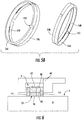
- FIG. 6 a cross-sectional view of the disclosed sealing set 25 disposed in relation to an exemplary piston rod 6 and stuffing box chamber portion 60 is shown.
- the inside diameters ID5, ID6 of the first and second seals 40, 42 are engaged with the outer surface 7 of the piston rod 6.
- a recess 9 is shown between the support ring 38, back-up ring 36 and first and second cover rings 40, 42 and the stuffing box chamber portion 60. In operation, this recess 9 may be pressurized with gas.
- the support ring 38 is on the high pressure side, and back-up ring 36 on the low pressure side. There is a clearance between the support ring 38 and the casing.
- the sealing rings 25, 125 include a pressure compensation feature for reducing the differential pressure across the first and second seal rings 44, 46; 144, 146.
- a pressure compensation feature for reducing the differential pressure across the first and second seal rings 44, 46; 144, 146.
- a partial circumferential groove 149 is provided in the second seal ring 146.
- the groove 149 can be pressurized or filled with gas from the high pressure side (i.e., the side adjacent to the first compression chamber 20), so the effective sealing area between the sealing ring 125 and the piston 6 is only the very small section of the second seal ring 146 from the groove 149 to the back-up ring 136.
- a small width "SW" of the sealing ring 146 is sealing against the piston rod 6, and pressure compensation is provided between the outer side 146a and the inner side 146b of the second seal ring 146. Pressure on the outside diameter OD6 and the inside diameter ID6 is equal, since the groove 149 is pressurized.
- the net sealing force is the pressure on the outer diameter (OD Pressure) of a seal times the supply pressure minus the average pressure under the seal.
- OD Pressure the pressure on the outer diameter
- FIG. 5 which includes a gap 149 between first and second seal rings 144, 146 the pressure gradient in the gap 149 between the sealing ring 125 and the piston rod 6 follows a hyperbolic function (see FIG. 7B ).
- the net radial force on the sealing ring 125 is caused by the pressure force on the outer diameter of the sealing ring minus the average pressure force under the sealing ring.
- the higher the average pressure under the sealing ring the lower the radial force.
- the pressure under the seal remains at a constant high value up to the end of the groove. In this way the radial force is partly compensated and friction is reduced.
- the gas pressure enters the groove 149 via an opening 151 ( FIG. 5B ) of the first sealing ring 144.
- the groove 149 can be vulnerable to mechanical damage. It can also become filled with debris during operation.
- FIGS. 2-4B illustrate a pressure compensation feature that does not include a groove in either sealing ring.
- the inventors have found that varying the widths of the first and second sealing rings 44, 46 can result in a desired pressure compensation result without the use of a groove.
- a relatively narrow first seal ring 44, and a relatively wide second seal ring 46 is used.
- the relatively wide second seal ring 46 has a width equal to the width of the ring of the prior embodiment including the groove ( see FIG. 7C ).
- the pressure compensation effect is the same as with the grooved ring set.
- the material of the first and second seal rings 44, 46 may be selected to have a small friction coefficient, reducing friction even further.
- the seal rings 44, 46 may be made from out of a modified PEEK material sold under the trade name LUVOCOM 1105-8160, Lehmann &Voss & Co. Alsterufer 19, D-20354 Hamburg, Germany. This material is capable of withstanding high internal loads caused by pressure compensation at high pressures. Additionally, this material has a high resistance to contamination by (water) particles is high due to its high hardness, which allows the seal rings to be machined to have very smooth surfaces.
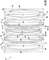
- FIG. 8 illustrates an exemplary stuffingbox case 24 that includes the disclosed sealing ring set 25.
- the stuffingbox case 24 includes a vent ring set 62, three sets of sealing rings 25, and one pressure breaker set 64.
- Gas coupling connections 66, 68 are disposed within the stuffingbox case 24 and may be routed to provide gas to selected locations adjacent one or more of the vent ring set 62, the sealing rings 25 and the pressure breaker set 64.
- FIG. 9 is a graph illustrating a comparison of frictional power, in a Nitrogen atmosphere, between a ring set including the disclose sealing ring 25 and a conventional ring set.
- frictional power associated with the conventional ring set rises to a maximum of about 2550 Watts at a static pressure of about 50 bars.
- the frictional power is about 1000 Watts.
- Frictional power for the ring set including the disclosed sealing ring 25 tops out at about 1200 Watts at a static pressure of about 100 bars.
- frictional power is substantially lower than conventional sealing arrangements. This results in substantially reduced heat generated during opertion, and substantially less wear of the sealing elements. For other non oxidizing gases the same drop in frictional power is expected.
Landscapes
- Engineering & Computer Science (AREA)
- General Engineering & Computer Science (AREA)
- Mechanical Engineering (AREA)
- Physics & Mathematics (AREA)
- Architecture (AREA)
- Fluid Mechanics (AREA)
- Sealing Devices (AREA)
- Compressor (AREA)
Claims (10)
- Un anneau d'étanchéification (25, 125) pour une utilisation dans un presse-garniture d'un compresseur à piston, l'anneau d'étanchéification (25, 125) comprenant :des premier et deuxième anneaux d'étanchéité (44, 46, 144, 146) en prise le long de surfaces latérales respectives ;des premier et deuxième anneaux de couverture (40, 42, 140, 142) disposés autour des premier et deuxième anneaux d'étanchéité (44, 46, 144, 146) de sorte que les diamètres extérieurs (OD5, OD6) des premier et deuxième anneaux d'étanchéité se mettent en prise avec les diamètres intérieurs (ID3, ID4) des premier et deuxième anneaux de couverture, respectivement ;caractérisé en ce que ledit anneau d'étanchéification (25, 125) comprend en sus :un anneau de support (38, 138) en prise avec le premier anneau d'étanchéité (44, 144) et le premier anneau de couverture (40, 140) ; etun anneau de renfort (36, 136) en prise avec le deuxième anneau d'étanchéité (46, 146) et le deuxième anneau de couverture (42, 142).
- L'anneau d'étanchéification de la revendication 1, dans lequel le premier anneau d'étanchéité (44) a une largeur qui est plus petite qu'une largeur du deuxième anneau d'étanchéité (46).
- L'anneau d'étanchéification de la revendication 1, dans lequel le deuxième anneau d'étanchéité (146) a une rainure circonférentielle (149) formée sur une surface intérieure de celui-ci, la rainure étant disposée de façon directement adjacente au premier anneau d'étanchéité (144).
- L'anneau d'étanchéification de la revendication 3, dans lequel le premier anneau d'étanchéité (144) a une ouverture (151) traversant une largeur dudit premier anneau d'étanchéité afin de fournir une veine gazeuse entre une surface extérieure dudit anneau d'étanchéification à ladite rainure (149).
- L'anneau d'étanchéification de la revendication 1, dans lequel les premier et deuxième anneaux d'étanchéité (44, 46) incluent des première et deuxième languettes (49, 51), et les premier et deuxième anneaux de couverture (40, 42) incluent des première et deuxième rainures (53, 55) à l'intérieur desquelles lesdites première et deuxième languettes sont reçues afin d'empêcher une rotation relative entre ceux-là.
- L'anneau d'étanchéification de la revendication 1, dans lequel le premier anneau d'étanchéité (44) a une ouverture (57) traversant une largeur dudit premier anneau d'étanchéité afin de permettre au premier anneau d'étanchéité de se dilater et de se contracter, et le deuxième anneau d'étanchéité (46) a une ouverture (59) traversant une largeur dudit deuxième anneau d'étanchéité afin de permettre au deuxième anneau d'étanchéité de se dilater et de se contracter.
- L'anneau d'étanchéification de la revendication 6, dans lequel le premier anneau de couverture (40) a une ouverture (53) traversant une largeur dudit premier anneau de couverture afin de permettre au premier anneau de couverture de se dilater et de se contracter avec ledit premier anneau d'étanchéité (44), et le deuxième anneau de couverture (42) a une ouverture (55) traversant une largeur dudit deuxième anneau de couverture afin de permettre au deuxième anneau de couverture de se dilater et de se contracter avec ledit deuxième anneau d'étanchéité (46).
- L'anneau d'étanchéification de la revendication 1, dans lequel les premier et deuxième anneaux d'étanchéité (44, 46) comprennent du PEEK imprégné d'un nano-matériau.
- L'anneau d'étanchéification de la revendication 1, dans lequel le premier anneau d'étanchéité (44) a une largeur (W5) qui est égale à une largeur (W3) du premier anneau de couverture (40) et le deuxième anneau d'étanchéité (46) a une largeur (W6) qui est égale à une largeur (W4) du deuxième anneau de couverture (42).
- L'anneau d'étanchéification de la revendication 9, dans lequel la largeur (W3) du premier anneau de couverture (40) est plus petite que la largeur (W4) du deuxième anneau de couverture (42).
Priority Applications (2)
| Application Number | Priority Date | Filing Date | Title |
|---|---|---|---|
| EP19157708.9A EP3517807B1 (fr) | 2013-12-10 | 2013-12-10 | Presse-étoupe de bague d'étanchéité individuel |
| ES19157708T ES2891982T3 (es) | 2013-12-10 | 2013-12-10 | Caja de empaquetadura con anillo de sellado único |
Applications Claiming Priority (1)
| Application Number | Priority Date | Filing Date | Title |
|---|---|---|---|
| PCT/EP2013/076141 WO2015086050A1 (fr) | 2013-12-10 | 2013-12-10 | Presse-garniture à anneau d'étanchéité unique |
Related Child Applications (1)
| Application Number | Title | Priority Date | Filing Date |
|---|---|---|---|
| EP19157708.9A Division EP3517807B1 (fr) | 2013-12-10 | 2013-12-10 | Presse-étoupe de bague d'étanchéité individuel |
Publications (2)
| Publication Number | Publication Date |
|---|---|
| EP3080490A1 EP3080490A1 (fr) | 2016-10-19 |
| EP3080490B1 true EP3080490B1 (fr) | 2019-02-20 |
Family
ID=49876563
Family Applications (2)
| Application Number | Title | Priority Date | Filing Date |
|---|---|---|---|
| EP19157708.9A Active EP3517807B1 (fr) | 2013-12-10 | 2013-12-10 | Presse-étoupe de bague d'étanchéité individuel |
| EP13811414.5A Active EP3080490B1 (fr) | 2013-12-10 | 2013-12-10 | Presse-garniture à anneau d'étanchéité unique |
Family Applications Before (1)
| Application Number | Title | Priority Date | Filing Date |
|---|---|---|---|
| EP19157708.9A Active EP3517807B1 (fr) | 2013-12-10 | 2013-12-10 | Presse-étoupe de bague d'étanchéité individuel |
Country Status (9)
| Country | Link |
|---|---|
| US (2) | US9856983B2 (fr) |
| EP (2) | EP3517807B1 (fr) |
| JP (1) | JP6280989B2 (fr) |
| KR (1) | KR101906021B1 (fr) |
| CN (2) | CN105814344B (fr) |
| CA (1) | CA2931699C (fr) |
| ES (2) | ES2891982T3 (fr) |
| RU (1) | RU2636284C1 (fr) |
| WO (1) | WO2015086050A1 (fr) |
Families Citing this family (15)
| Publication number | Priority date | Publication date | Assignee | Title |
|---|---|---|---|---|
| DE102014223164B4 (de) * | 2014-11-13 | 2022-03-17 | Zf Friedrichshafen Ag | Dichtungsführungseinheit |
| GB2542508A (en) * | 2015-09-18 | 2017-03-22 | Victrex Mfg Ltd | Polymeric materials |
| USD792474S1 (en) | 2016-02-02 | 2017-07-18 | Ge Oil & Gas Compression Systems, Llc | Dual compressor nozzle |
| US20170335972A1 (en) * | 2016-05-17 | 2017-11-23 | Compressor Products International, Llc | Rod packing |
| US10215190B2 (en) | 2016-05-31 | 2019-02-26 | GE Oil & Gas, Inc. | Refrigerant compressing process with cooled motor |
| KR101951652B1 (ko) * | 2017-05-18 | 2019-02-25 | 뉴모텍(주) | 소형 공기 압축기의 실린더 결합 구조 |
| US10520086B2 (en) | 2017-07-11 | 2019-12-31 | T-Lon Products, Inc. | Apparatus and systems for preventing extrusion |
| KR102164245B1 (ko) * | 2018-10-01 | 2020-10-12 | 주식회사 대경산전 | 가스켓 및 이를 포함하는 태양광 접속반 |
| CN110107584B (zh) * | 2019-04-30 | 2020-09-22 | 东北大学 | 一种盾构隧道螺栓接头的防水密封装置 |
| CN110067862A (zh) * | 2019-05-06 | 2019-07-30 | 北京化工大学 | 一种搅拌釜用密封装置、系统及密封控制方法 |
| EP3875807A1 (fr) * | 2020-03-03 | 2021-09-08 | Burckhardt Compression AG | Agencement de segment de piston, compresseur à piston ainsi que procédé d'étanchéification d'un espace de compression |
| EP3961034B1 (fr) * | 2020-08-31 | 2025-04-23 | Burckhardt Compression AG | Bague d'étranglement |
| CN112539153B (zh) * | 2020-11-27 | 2022-12-09 | 中石化石油机械股份有限公司研究院 | 压缩机组合活塞环 |
| CN116753207A (zh) * | 2023-07-27 | 2023-09-15 | 鸿正联塑(浙江)机械有限公司 | 一种二板注塑机锁模高压油缸机构及安装方法 |
| WO2025199229A1 (fr) * | 2024-03-19 | 2025-09-25 | Dover Pumps & Process Solutions Segment, Inc. | Boîte à garniture à anneaux composites |
Family Cites Families (30)
| Publication number | Priority date | Publication date | Assignee | Title |
|---|---|---|---|---|
| GB599983A (en) * | 1945-09-27 | 1948-03-25 | William Marsden Kermode | Improvements in or relating to metallic packings for stuffing boxes |
| GB438930A (en) * | 1935-03-14 | 1935-11-26 | Paul Barry | Improvements in stuffing box packings |
| US3271037A (en) * | 1963-04-01 | 1966-09-06 | Garlock Inc | Pressure-balanced segmental packing rings |
| US3490774A (en) * | 1966-03-29 | 1970-01-20 | Dresser Ind | Packing for a reciprocal plunger rod |
| DE1926102A1 (de) * | 1969-05-22 | 1970-11-26 | Borsig Gmbh | Dichtung fuer Kolbenstangen und Kolben von Kolbenmaschinen fuer hohe Druecke |
| US3711104A (en) * | 1971-03-16 | 1973-01-16 | Dresser Ind | Seal assembly |
| JPS5770554U (fr) * | 1980-10-17 | 1982-04-28 | ||
| JPS60123459A (ja) | 1983-12-08 | 1985-07-02 | Toray Ind Inc | グアニジン誘導体またはその酸付加塩および農園芸用殺菌剤 |
| JPS60123459U (ja) * | 1984-01-27 | 1985-08-20 | エヌオーケー株式会社 | 密封装置 |
| SU1303777A1 (ru) * | 1985-08-19 | 1987-04-15 | Предприятие П/Я В-8710 | Уплотнительное устройство |
| JPS62170867U (fr) * | 1986-04-18 | 1987-10-29 | ||
| US5014999A (en) * | 1989-03-06 | 1991-05-14 | Car-Graph, Inc. | Pressure enhanced self aligning seal |
| RU2016308C1 (ru) | 1991-06-13 | 1994-07-15 | Ленинградское научно-производственное объединение химического машиностроения | Уплотнение штока или плунжера |
| JPH0544645A (ja) * | 1991-08-07 | 1993-02-23 | Toshiba Corp | シール装置 |
| DE4201246C2 (de) * | 1992-01-18 | 1993-12-16 | Pacific Wietz Gmbh & Co Kg | Dichtungsanordnung für eine im Querschnitt kreisförmige Kolbenstange, insbesondere an Kolbenkompressoren |
| US5217232A (en) | 1992-04-28 | 1993-06-08 | Car-Graph, Inc. | Thermally regulated segmented seal |
| DE19506083A1 (de) | 1995-02-22 | 1995-07-13 | Thueringisches Inst Textil | Hybridvliese mit haftungsverbessernden Eigenschaften für faserverstärkte Kunststoffe |
| DE19506683C2 (de) * | 1995-02-25 | 1999-07-15 | Neuman & Esser | Kolbenstangendichtung |
| JP3292128B2 (ja) | 1998-02-27 | 2002-06-17 | ダイキン工業株式会社 | プレート型熱交換器 |
| JP3139681B2 (ja) | 1999-05-31 | 2001-03-05 | 春男 上原 | 凝縮器 |
| AT411384B (de) * | 2000-04-10 | 2003-12-29 | Hoerbiger Ventilwerke Gmbh | Dichtring-kombination |
| JP2002122243A (ja) * | 2000-10-17 | 2002-04-26 | Eagle Ind Co Ltd | 分割型シール |
| JP4207184B2 (ja) | 2002-08-30 | 2009-01-14 | 株式会社ティラド | プレート型熱交換器およびその製造方法 |
| GB2429054A (en) | 2005-07-29 | 2007-02-14 | Howden Power Ltd | A heating surface element |
| JP2008106823A (ja) * | 2006-10-24 | 2008-05-08 | Toyota Motor Corp | シール構造 |
| US7717433B2 (en) * | 2007-05-03 | 2010-05-18 | Equistar Chemicals, Lp | Dynamic seal assembly |
| AT505293B1 (de) * | 2007-11-15 | 2008-12-15 | Hoerbiger Kompressortech Hold | Packungsring-kombination |
| US9557119B2 (en) | 2009-05-08 | 2017-01-31 | Arvos Inc. | Heat transfer sheet for rotary regenerative heat exchanger |
| EP2423539B1 (fr) * | 2010-08-31 | 2014-04-02 | Burckhardt Compression AG | Agencement d'étanchéification |
| CN202195052U (zh) * | 2011-08-20 | 2012-04-18 | 常州朗博汽车零部件有限公司 | 分体镶嵌咬合成型密封圈 |
-
2013
- 2013-12-10 JP JP2016536926A patent/JP6280989B2/ja active Active
- 2013-12-10 CA CA2931699A patent/CA2931699C/fr active Active
- 2013-12-10 US US15/101,249 patent/US9856983B2/en active Active
- 2013-12-10 WO PCT/EP2013/076141 patent/WO2015086050A1/fr not_active Ceased
- 2013-12-10 EP EP19157708.9A patent/EP3517807B1/fr active Active
- 2013-12-10 CN CN201380081494.4A patent/CN105814344B/zh active Active
- 2013-12-10 RU RU2016127557A patent/RU2636284C1/ru active
- 2013-12-10 ES ES19157708T patent/ES2891982T3/es active Active
- 2013-12-10 CN CN201910108199.2A patent/CN109780213B/zh active Active
- 2013-12-10 EP EP13811414.5A patent/EP3080490B1/fr active Active
- 2013-12-10 KR KR1020167015049A patent/KR101906021B1/ko active Active
- 2013-12-10 ES ES13811414T patent/ES2719778T3/es active Active
-
2017
- 2017-11-30 US US15/826,826 patent/US10184563B2/en active Active
Non-Patent Citations (1)
| Title |
|---|
| None * |
Also Published As
| Publication number | Publication date |
|---|---|
| RU2636284C1 (ru) | 2017-11-21 |
| EP3517807B1 (fr) | 2021-08-25 |
| US20180080561A1 (en) | 2018-03-22 |
| KR101906021B1 (ko) | 2018-10-08 |
| EP3080490A1 (fr) | 2016-10-19 |
| ES2719778T3 (es) | 2019-07-16 |
| KR20160083095A (ko) | 2016-07-11 |
| EP3517807A1 (fr) | 2019-07-31 |
| CA2931699C (fr) | 2018-06-12 |
| JP2017500509A (ja) | 2017-01-05 |
| US9856983B2 (en) | 2018-01-02 |
| JP6280989B2 (ja) | 2018-02-14 |
| US20160305551A1 (en) | 2016-10-20 |
| CN105814344B (zh) | 2019-03-08 |
| CN105814344A (zh) | 2016-07-27 |
| ES2891982T3 (es) | 2022-02-01 |
| CN109780213A (zh) | 2019-05-21 |
| US10184563B2 (en) | 2019-01-22 |
| CA2931699A1 (fr) | 2015-06-18 |
| CN109780213B (zh) | 2021-06-08 |
| WO2015086050A1 (fr) | 2015-06-18 |
Similar Documents
| Publication | Publication Date | Title |
|---|---|---|
| EP3080490B1 (fr) | Presse-garniture à anneau d'étanchéité unique | |
| US9933071B2 (en) | Seal and method of manufacturing and/or using same | |
| WO2019208182A1 (fr) | Segment de piston et compresseur | |
| US20100132381A1 (en) | Low wear piston sleeve | |
| US12209670B2 (en) | Piston ring for a piston compressor | |
| JP2020530542A (ja) | 間隙カバー要素を有するピストンシールリングアセンブリ | |
| US8251372B2 (en) | Cartridge and related methods | |
| CN110005815A (zh) | 密封装置、轴组件和轴承 | |
| US7966925B2 (en) | Combination mismatched metal-to-metal seal and O-ring seal with vent hole in between for high temperature and high pressure environment | |
| JP4103708B2 (ja) | スクリュー圧縮機 | |
| US20210033192A1 (en) | Axially preloaded packing ring sets | |
| EP3130759B1 (fr) | Joint à membrane de turbine à gaz | |
| US20230349465A1 (en) | Laterally moveable compressor piston rod lip seal assembly | |
| US20250146575A1 (en) | Laterally moveable compressor piston rod lip seal assembly | |
| USRE31329E (en) | Packing rings | |
| CN219344953U (zh) | 滚子结构、泵体组件、流体机械及换热设备 | |
| CN121719720A (zh) | 一种活塞气体压缩机用填料组件 | |
| EP0367317A1 (fr) | Agencement pour garniture annulaire pour mouvement linéaire alternatif |
Legal Events
| Date | Code | Title | Description |
|---|---|---|---|
| PUAI | Public reference made under article 153(3) epc to a published international application that has entered the european phase |
Free format text: ORIGINAL CODE: 0009012 |
|
| 17P | Request for examination filed |
Effective date: 20160530 |
|
| AK | Designated contracting states |
Kind code of ref document: A1 Designated state(s): AL AT BE BG CH CY CZ DE DK EE ES FI FR GB GR HR HU IE IS IT LI LT LU LV MC MK MT NL NO PL PT RO RS SE SI SK SM TR |
|
| AX | Request for extension of the european patent |
Extension state: BA ME |
|
| DAX | Request for extension of the european patent (deleted) | ||
| GRAP | Despatch of communication of intention to grant a patent |
Free format text: ORIGINAL CODE: EPIDOSNIGR1 |
|
| STAA | Information on the status of an ep patent application or granted ep patent |
Free format text: STATUS: GRANT OF PATENT IS INTENDED |
|
| INTG | Intention to grant announced |
Effective date: 20180801 |
|
| GRAJ | Information related to disapproval of communication of intention to grant by the applicant or resumption of examination proceedings by the epo deleted |
Free format text: ORIGINAL CODE: EPIDOSDIGR1 |
|
| STAA | Information on the status of an ep patent application or granted ep patent |
Free format text: STATUS: REQUEST FOR EXAMINATION WAS MADE |
|
| GRAR | Information related to intention to grant a patent recorded |
Free format text: ORIGINAL CODE: EPIDOSNIGR71 |
|
| GRAS | Grant fee paid |
Free format text: ORIGINAL CODE: EPIDOSNIGR3 |
|
| STAA | Information on the status of an ep patent application or granted ep patent |
Free format text: STATUS: GRANT OF PATENT IS INTENDED |
|
| INTC | Intention to grant announced (deleted) | ||
| INTG | Intention to grant announced |
Effective date: 20181207 |
|
| GRAA | (expected) grant |
Free format text: ORIGINAL CODE: 0009210 |
|
| STAA | Information on the status of an ep patent application or granted ep patent |
Free format text: STATUS: THE PATENT HAS BEEN GRANTED |
|
| AK | Designated contracting states |
Kind code of ref document: B1 Designated state(s): AL AT BE BG CH CY CZ DE DK EE ES FI FR GB GR HR HU IE IS IT LI LT LU LV MC MK MT NL NO PL PT RO RS SE SI SK SM TR |
|
| REG | Reference to a national code |
Ref country code: GB Ref legal event code: FG4D |
|
| REG | Reference to a national code |
Ref country code: CH Ref legal event code: EP |
|
| REG | Reference to a national code |
Ref country code: DE Ref legal event code: R096 Ref document number: 602013051080 Country of ref document: DE |
|
| REG | Reference to a national code |
Ref country code: AT Ref legal event code: REF Ref document number: 1098619 Country of ref document: AT Kind code of ref document: T Effective date: 20190315 |
|
| REG | Reference to a national code |
Ref country code: IE Ref legal event code: FG4D |
|
| REG | Reference to a national code |
Ref country code: NL Ref legal event code: FP |
|
| REG | Reference to a national code |
Ref country code: LT Ref legal event code: MG4D |
|
| REG | Reference to a national code |
Ref country code: ES Ref legal event code: FG2A Ref document number: 2719778 Country of ref document: ES Kind code of ref document: T3 Effective date: 20190716 |
|
| PG25 | Lapsed in a contracting state [announced via postgrant information from national office to epo] |
Ref country code: LT Free format text: LAPSE BECAUSE OF FAILURE TO SUBMIT A TRANSLATION OF THE DESCRIPTION OR TO PAY THE FEE WITHIN THE PRESCRIBED TIME-LIMIT Effective date: 20190220 Ref country code: FI Free format text: LAPSE BECAUSE OF FAILURE TO SUBMIT A TRANSLATION OF THE DESCRIPTION OR TO PAY THE FEE WITHIN THE PRESCRIBED TIME-LIMIT Effective date: 20190220 Ref country code: PT Free format text: LAPSE BECAUSE OF FAILURE TO SUBMIT A TRANSLATION OF THE DESCRIPTION OR TO PAY THE FEE WITHIN THE PRESCRIBED TIME-LIMIT Effective date: 20190620 Ref country code: NO Free format text: LAPSE BECAUSE OF FAILURE TO SUBMIT A TRANSLATION OF THE DESCRIPTION OR TO PAY THE FEE WITHIN THE PRESCRIBED TIME-LIMIT Effective date: 20190520 Ref country code: SE Free format text: LAPSE BECAUSE OF FAILURE TO SUBMIT A TRANSLATION OF THE DESCRIPTION OR TO PAY THE FEE WITHIN THE PRESCRIBED TIME-LIMIT Effective date: 20190220 |
|
| PG25 | Lapsed in a contracting state [announced via postgrant information from national office to epo] |
Ref country code: GR Free format text: LAPSE BECAUSE OF FAILURE TO SUBMIT A TRANSLATION OF THE DESCRIPTION OR TO PAY THE FEE WITHIN THE PRESCRIBED TIME-LIMIT Effective date: 20190521 Ref country code: HR Free format text: LAPSE BECAUSE OF FAILURE TO SUBMIT A TRANSLATION OF THE DESCRIPTION OR TO PAY THE FEE WITHIN THE PRESCRIBED TIME-LIMIT Effective date: 20190220 Ref country code: IS Free format text: LAPSE BECAUSE OF FAILURE TO SUBMIT A TRANSLATION OF THE DESCRIPTION OR TO PAY THE FEE WITHIN THE PRESCRIBED TIME-LIMIT Effective date: 20190620 Ref country code: LV Free format text: LAPSE BECAUSE OF FAILURE TO SUBMIT A TRANSLATION OF THE DESCRIPTION OR TO PAY THE FEE WITHIN THE PRESCRIBED TIME-LIMIT Effective date: 20190220 Ref country code: BG Free format text: LAPSE BECAUSE OF FAILURE TO SUBMIT A TRANSLATION OF THE DESCRIPTION OR TO PAY THE FEE WITHIN THE PRESCRIBED TIME-LIMIT Effective date: 20190520 Ref country code: RS Free format text: LAPSE BECAUSE OF FAILURE TO SUBMIT A TRANSLATION OF THE DESCRIPTION OR TO PAY THE FEE WITHIN THE PRESCRIBED TIME-LIMIT Effective date: 20190220 |
|
| REG | Reference to a national code |
Ref country code: AT Ref legal event code: MK05 Ref document number: 1098619 Country of ref document: AT Kind code of ref document: T Effective date: 20190220 |
|
| PG25 | Lapsed in a contracting state [announced via postgrant information from national office to epo] |
Ref country code: AL Free format text: LAPSE BECAUSE OF FAILURE TO SUBMIT A TRANSLATION OF THE DESCRIPTION OR TO PAY THE FEE WITHIN THE PRESCRIBED TIME-LIMIT Effective date: 20190220 Ref country code: CZ Free format text: LAPSE BECAUSE OF FAILURE TO SUBMIT A TRANSLATION OF THE DESCRIPTION OR TO PAY THE FEE WITHIN THE PRESCRIBED TIME-LIMIT Effective date: 20190220 Ref country code: DK Free format text: LAPSE BECAUSE OF FAILURE TO SUBMIT A TRANSLATION OF THE DESCRIPTION OR TO PAY THE FEE WITHIN THE PRESCRIBED TIME-LIMIT Effective date: 20190220 Ref country code: EE Free format text: LAPSE BECAUSE OF FAILURE TO SUBMIT A TRANSLATION OF THE DESCRIPTION OR TO PAY THE FEE WITHIN THE PRESCRIBED TIME-LIMIT Effective date: 20190220 Ref country code: SK Free format text: LAPSE BECAUSE OF FAILURE TO SUBMIT A TRANSLATION OF THE DESCRIPTION OR TO PAY THE FEE WITHIN THE PRESCRIBED TIME-LIMIT Effective date: 20190220 Ref country code: RO Free format text: LAPSE BECAUSE OF FAILURE TO SUBMIT A TRANSLATION OF THE DESCRIPTION OR TO PAY THE FEE WITHIN THE PRESCRIBED TIME-LIMIT Effective date: 20190220 |
|
| REG | Reference to a national code |
Ref country code: DE Ref legal event code: R097 Ref document number: 602013051080 Country of ref document: DE |
|
| PG25 | Lapsed in a contracting state [announced via postgrant information from national office to epo] |
Ref country code: PL Free format text: LAPSE BECAUSE OF FAILURE TO SUBMIT A TRANSLATION OF THE DESCRIPTION OR TO PAY THE FEE WITHIN THE PRESCRIBED TIME-LIMIT Effective date: 20190220 Ref country code: SM Free format text: LAPSE BECAUSE OF FAILURE TO SUBMIT A TRANSLATION OF THE DESCRIPTION OR TO PAY THE FEE WITHIN THE PRESCRIBED TIME-LIMIT Effective date: 20190220 |
|
| PLBE | No opposition filed within time limit |
Free format text: ORIGINAL CODE: 0009261 |
|
| STAA | Information on the status of an ep patent application or granted ep patent |
Free format text: STATUS: NO OPPOSITION FILED WITHIN TIME LIMIT |
|
| PG25 | Lapsed in a contracting state [announced via postgrant information from national office to epo] |
Ref country code: AT Free format text: LAPSE BECAUSE OF FAILURE TO SUBMIT A TRANSLATION OF THE DESCRIPTION OR TO PAY THE FEE WITHIN THE PRESCRIBED TIME-LIMIT Effective date: 20190220 |
|
| 26N | No opposition filed |
Effective date: 20191121 |
|
| PG25 | Lapsed in a contracting state [announced via postgrant information from national office to epo] |
Ref country code: SI Free format text: LAPSE BECAUSE OF FAILURE TO SUBMIT A TRANSLATION OF THE DESCRIPTION OR TO PAY THE FEE WITHIN THE PRESCRIBED TIME-LIMIT Effective date: 20190220 |
|
| PG25 | Lapsed in a contracting state [announced via postgrant information from national office to epo] |
Ref country code: TR Free format text: LAPSE BECAUSE OF FAILURE TO SUBMIT A TRANSLATION OF THE DESCRIPTION OR TO PAY THE FEE WITHIN THE PRESCRIBED TIME-LIMIT Effective date: 20190220 |
|
| REG | Reference to a national code |
Ref country code: CH Ref legal event code: PL |
|
| PG25 | Lapsed in a contracting state [announced via postgrant information from national office to epo] |
Ref country code: MC Free format text: LAPSE BECAUSE OF FAILURE TO SUBMIT A TRANSLATION OF THE DESCRIPTION OR TO PAY THE FEE WITHIN THE PRESCRIBED TIME-LIMIT Effective date: 20190220 |
|
| GBPC | Gb: european patent ceased through non-payment of renewal fee |
Effective date: 20191210 |
|
| PG25 | Lapsed in a contracting state [announced via postgrant information from national office to epo] |
Ref country code: LU Free format text: LAPSE BECAUSE OF NON-PAYMENT OF DUE FEES Effective date: 20191210 Ref country code: IE Free format text: LAPSE BECAUSE OF NON-PAYMENT OF DUE FEES Effective date: 20191210 Ref country code: GB Free format text: LAPSE BECAUSE OF NON-PAYMENT OF DUE FEES Effective date: 20191210 |
|
| PG25 | Lapsed in a contracting state [announced via postgrant information from national office to epo] |
Ref country code: CH Free format text: LAPSE BECAUSE OF NON-PAYMENT OF DUE FEES Effective date: 20191231 Ref country code: LI Free format text: LAPSE BECAUSE OF NON-PAYMENT OF DUE FEES Effective date: 20191231 |
|
| PG25 | Lapsed in a contracting state [announced via postgrant information from national office to epo] |
Ref country code: CY Free format text: LAPSE BECAUSE OF FAILURE TO SUBMIT A TRANSLATION OF THE DESCRIPTION OR TO PAY THE FEE WITHIN THE PRESCRIBED TIME-LIMIT Effective date: 20190220 |
|
| PG25 | Lapsed in a contracting state [announced via postgrant information from national office to epo] |
Ref country code: HU Free format text: LAPSE BECAUSE OF FAILURE TO SUBMIT A TRANSLATION OF THE DESCRIPTION OR TO PAY THE FEE WITHIN THE PRESCRIBED TIME-LIMIT; INVALID AB INITIO Effective date: 20131210 Ref country code: MT Free format text: LAPSE BECAUSE OF FAILURE TO SUBMIT A TRANSLATION OF THE DESCRIPTION OR TO PAY THE FEE WITHIN THE PRESCRIBED TIME-LIMIT Effective date: 20190220 |
|
| PG25 | Lapsed in a contracting state [announced via postgrant information from national office to epo] |
Ref country code: MK Free format text: LAPSE BECAUSE OF FAILURE TO SUBMIT A TRANSLATION OF THE DESCRIPTION OR TO PAY THE FEE WITHIN THE PRESCRIBED TIME-LIMIT Effective date: 20190220 |
|
| P01 | Opt-out of the competence of the unified patent court (upc) registered |
Effective date: 20230531 |
|
| PGFP | Annual fee paid to national office [announced via postgrant information from national office to epo] |
Ref country code: IT Payment date: 20251219 Year of fee payment: 13 |
|
| PGFP | Annual fee paid to national office [announced via postgrant information from national office to epo] |
Ref country code: NL Payment date: 20251226 Year of fee payment: 13 Ref country code: FR Payment date: 20251226 Year of fee payment: 13 |
|
| PGFP | Annual fee paid to national office [announced via postgrant information from national office to epo] |
Ref country code: BE Payment date: 20251229 Year of fee payment: 13 |
|
| PGFP | Annual fee paid to national office [announced via postgrant information from national office to epo] |
Ref country code: ES Payment date: 20260102 Year of fee payment: 13 |
|
| PGFP | Annual fee paid to national office [announced via postgrant information from national office to epo] |
Ref country code: DE Payment date: 20251229 Year of fee payment: 13 |