EP3080543B1 - Système d'enroulement de fibre pour structure de type canon composite pour projectile - Google Patents
Système d'enroulement de fibre pour structure de type canon composite pour projectile Download PDFInfo
- Publication number
- EP3080543B1 EP3080543B1 EP14883548.1A EP14883548A EP3080543B1 EP 3080543 B1 EP3080543 B1 EP 3080543B1 EP 14883548 A EP14883548 A EP 14883548A EP 3080543 B1 EP3080543 B1 EP 3080543B1
- Authority
- EP
- European Patent Office
- Prior art keywords
- barrel
- inner liner
- cfc
- outer shell
- intermediate region
- Prior art date
- Legal status (The legal status is an assumption and is not a legal conclusion. Google has not performed a legal analysis and makes no representation as to the accuracy of the status listed.)
- Active
Links
Images


Classifications
-
- F—MECHANICAL ENGINEERING; LIGHTING; HEATING; WEAPONS; BLASTING
- F41—WEAPONS
- F41A—FUNCTIONAL FEATURES OR DETAILS COMMON TO BOTH SMALLARMS AND ORDNANCE, e.g. CANNONS; MOUNTINGS FOR SMALLARMS OR ORDNANCE
- F41A21/00—Barrels; Gun tubes; Muzzle attachments; Barrel mounting means
- F41A21/02—Composite barrels, i.e. barrels having multiple layers, e.g. of different materials
-
- B—PERFORMING OPERATIONS; TRANSPORTING
- B32—LAYERED PRODUCTS
- B32B—LAYERED PRODUCTS, i.e. PRODUCTS BUILT-UP OF STRATA OF FLAT OR NON-FLAT, e.g. CELLULAR OR HONEYCOMB, FORM
- B32B15/00—Layered products comprising a layer of metal
- B32B15/14—Layered products comprising a layer of metal next to a fibrous or filamentary layer
-
- F—MECHANICAL ENGINEERING; LIGHTING; HEATING; WEAPONS; BLASTING
- F41—WEAPONS
- F41A—FUNCTIONAL FEATURES OR DETAILS COMMON TO BOTH SMALLARMS AND ORDNANCE, e.g. CANNONS; MOUNTINGS FOR SMALLARMS OR ORDNANCE
- F41A21/00—Barrels; Gun tubes; Muzzle attachments; Barrel mounting means
- F41A21/02—Composite barrels, i.e. barrels having multiple layers, e.g. of different materials
- F41A21/04—Barrel liners
-
- F—MECHANICAL ENGINEERING; LIGHTING; HEATING; WEAPONS; BLASTING
- F41—WEAPONS
- F41A—FUNCTIONAL FEATURES OR DETAILS COMMON TO BOTH SMALLARMS AND ORDNANCE, e.g. CANNONS; MOUNTINGS FOR SMALLARMS OR ORDNANCE
- F41A21/00—Barrels; Gun tubes; Muzzle attachments; Barrel mounting means
- F41A21/20—Barrels or gun tubes characterised by the material
Definitions
- the carbon fibers used in the outer shell may be any types that provide the desired stiffness, strength and thermal conductivity. Typically for gun barrel applications, polyacrylonitrile ("PAN”) precursor or pitch precursor carbon fibers are used.
- PAN polyacrylonitrile
- the carbon fiber may be applied in a wet filament winding operation, wherein dry carbon fiber strands or tows are combined with a resin in a "wet" dip pan process, then wound around the inner liner and processed.
- the shell may be fabricated from carbon fiber tow, unidirectional tape, or fabric that was previously impregnated with resin in a separate process ("towpreg” or "prepreg"), or a textile preform wherein the resin is infused into the braided preform, then applied to the inner liner in a process that cures the prepreg into a hard thermally stable matrix and simultaneously bonds the outer shell to the barrel inner liner.
- the matrix resin is typically a crosslinkable epoxy, but the resin may be a polymer such as a polyimide, bismaleimide, cyanate ester, inorganic polymer, thermoplastic polymer, or some other material as the inventors described in patent application PCT/US14/53194 (Curliss ).
- the matrix binder may not be an organic polymer resin at all, but may be an inorganic polymer, a metal, a ceramic, allotropes of carbon, or a mineral.
- the composite barrel may then be cured (where relevant), finished, and attached to a receiver and stock.
- Such carbon fiber reinforced composites can provide a suitable balance of thermal properties, mechanical properties, and processing characteristics for many common firearms applications.
- Other fibers known to those skilled in the art including continuous glass fibers, continuous ceramic fibers, continuous metallic fibers, continuous graphite fibers, continuous mineral fibers, continuous polymer fibers and/or combinations thereof may also be used as the reinforcement phase.
- the composite must be constructed in a manner and quantity around and along the liner to ensure that the barrel does not burst upon firing, to achieve satisfactory strength and stiffness in the principal directions (e.g., axially and torsionally), to provide adequate environmental durability, and to dampen the shock wave that propagates when the projectile is fired.
- dampening of the shock wave through reflection, refraction, and interaction in inhomogeneous materials will vary depending on material properties, such as fiber diameter and geometric orientation, and volume fraction of the continuous fibers within the matrix.
- Torsional stiffness is a significant design factor important in medium and large caliber barrels having rifling.
- adding more layers of windings can lead to manufacturing and curing complications, higher material expense, more weight, and a bulkier barrel profile than desired.
- Fiber selection can also address these problems to some extent. Generally lower density, stronger and stiffer fibers are preferred provided they do not exhibit other undesirable characteristics, such as poor resin adhesion.
- thermal management is a significant concern, inasmuch as the more common continuous fiber composite ("CFC") outer shells are relatively poor conductors of the heat generated by hot gasses within the liner. Additional layers of CFC windings exacerbate the heat removal problem.
- the barrel will heat up.
- the matrix phase is an organic polymer
- T g glass transition temperature
- the CFC softens significantly and the mechanical integrity of the composite barrel is compromised.
- irreversible thermal decomposition of the cured matrix occurs and barrel structural integrity is further compromised.
- 6,889,464 added a thermally conductive material to the resin mixture to improve thermal conductivity and heat dissipation.
- Curliss, supra, PCT/US14/53194 ) disclosed a novel method for manufacturing gun barrels using resins that withstand higher temperatures, and disclosed using small particles of metal such as aluminum as a thermal conducting additive.
- a third problem relates to stresses within the barrel arising from thermal expansion differences between the composite and the inner liner of the composite barrel.
- the inner steel liner heats during operation, it expands both radially and longitudinally.
- Composite structures in the prior art have a substantially lower average effective coefficient of thermal expansion (CTE) in the longitudinal direction than steel and so when heated, the CFC outer shell expands substantially less than the steel liner. This may increase or decrease thermal stresses in the barrel depending on the state of thermal residual stress from processing. The point is that as the temperature changes in the barrel, due to operation or the environment, the state of residual stress in the barrel also changes.
- CTE average effective coefficient of thermal expansion
- the CTE of type 416 grade stainless steel is about 9.99 parts per million per degree Celsius (9.99 ppm/°C, or 9.99 ⁇ 10 -6 /°C) (5.55 parts per million per degree Fahrenheit -5.55 ppm/°F, or 5.55 ⁇ 10 -6 /°F), while the longitudinal average effective CTE for a typical CFC outer shell employing PAN precursor carbon fiber and a thermoset epoxy resin is less than about 5.4 ppm/ °C (3 ppm/ °F).
- US 5,600,912 (Smith ) teaches mechanical compression of the carbon fiber composite outer shell longitudinally after it is cured to improve barrel stiffness, which compression could also help compensate for a lower CFC thermal expansion when the barrel is heated during operation.
- mechanically compressing the CFC risks damage e.g., through over tightening, and in any case the "proper" amount of cold residual compression to apply will vary depending on the barrel's operating temperature as well as structural characteristics such as barrel length and liner profile.
- US 6,189,431 (Danner ) also mechanically exerts residual cold compression on the CFC, but it is accomplished by means of steel flanges on the liner ends which compress the CFC as the steel liner contracts more than the CFC during the cooling phase of the curing process.
- Danner does not address the underlying problem of mismatched CTEs, and seems to accept as a given that a steel liner inherently has a higher CTE than a continuous fiber composite. Moreover, Danner continues the prior art of abruptly alternating winding angles between layers.
- a barrel for directing the path of a dischargeable projectile comprising a novel continuous fiber composite outer shell that offers superior axial and torsional strength and stiffness, minimizes weight and radial bulk, and does not distort when heated due to mismatched axial CTEs between the inner liner and CFC outer shell.
- the invention comprises a barrel for directing the path of a dischargeable projectile including an inner liner defining an axial bore and having a coefficient of thermal expansion, and a CFC outer shell surrounding and in direct contact with the inner liner, wherein the average effective axial CTE of the CFC is approximately equal to the axial CTE of the inner liner.
- the invention may be practiced with projectile barrels of virtually any length, contour or caliber with comparable effectiveness, and on other structures where fiber is combined with a resin and wound or otherwise constructed around along an elongated axis.
- the invention is equally suitable to short handgun pistol barrels, small caliber sporting guns and military weapons, as well as medium and large caliber military weapons barrels such as barrels for the 25mm M242 Bushmaster, or the M256A1 120mm smooth bore main gun of the Abrams M1A2 tank.
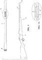
- Figure 1 shows a bolt action rifle 10 fitted with a receiver 12, stock, trigger, barrel 14, and other familiar features.
- barrel 14 securely engages with receiver 12 by means of threads 16.
- a cartridge of ammunition is inserted into the receiver.
- the cartridge has a base portion containing a gunpowder charge and dischargeable projectile, i.e ., a bullet.
- a firing pin strikes the base of the cartridge, igniting the gunpowder charge and causing the bullet to discharge through axial bore 24 and out of the muzzle 18.
- barrel 14 is comprised of an inner liner 22 and an outer shell 20.
- the liner may be fabricated from any metal or refractory material commonly used and known to be useful for firearms barrels or a combination of the foregoing.
- a steel alloy inner liner 22, such as AISI type 416 stainless steel, has good machining properties, facilitating precisely boring and rifling lands and grooves along axial bore 24 as well as threads at the muzzle and/or breech ends of the barrel.
- Other steel alloys, including other alloys in AISI classes 400 and 4000, have demonstrated good performance as gun barrel inner liners.
- Outer shell 20 is a continuous fiber composite (CFC).
- CFC means a composite comprised of continuous fibers such as continuous PAN and pitch carbon fibers, continuous glass fibers, continuous ceramic fibers, continuous metallic fibers, continuous graphite fibers, continuous mineral fibers, continuous polymer fibers, and combinations thereof; and a matrix binder material such as an organic polymer, an inorganic polymer, a metal, a ceramic, allotropes of carbon, or a mineral.
- Inner liner 22 need not be uniformly cylindrical.
- inner liner 22 may radially expand at the breech end to accommodate cutting of threads 16 for insertion into receiver 12, taper outwards at the muzzle 18, or include other configurations such as a gas block journal depending on desired features of the gun.
- Outer shell 20 likewise may include non-cylindrical features or be discontinuous over the length of barrel 14.
- Outer shell 20 is in direct contact with inner liner 22 at interface 26. It may be desirable to promote adhesion or to inhibit corrosion between the inner liner 22 and CFC outer shell 20 at interface 26.
- direct contact means that the outer surface of inner liner 22 at interface 26 may include a surface treatment that is applied before outer shell 20 is fabricated upon inner liner 22.
- a CFC outer shell 20 is in "direct contact” with a steel inner liner 22 at interface 26 even if the steel liner's surface is electroplated, anodized, or coated with a chemical compound or mixture, such as paint, resin, hot glass, or other substance.
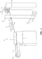
- FIG. 2 shows a simplified tow winding system 30 useful for fabricating a composite gun barrel 14 having a CFC outer shell 20.
- outer shell 20 comprises continuous fiber filament, or tow, 34, supplied from tow spool 32.
- the fiber could be in the form of fabric or a weave.
- Carbon fibers are typically advantageous to use for CFC gun barrels due to their high stiffness, high strength, and low density.
- the term "carbon fiber” is used to generically describe carbon and graphite fibers irrespective of their manufacturing process or precursor materials, and specifically includes both PAN precursor and pitch precursor carbon fibers.
- continuous fiber differentiates such essentially endless fiber from discontinuous fibers, e.g. chopped or ground carbon fibers.
- tow 34 is an intermediate modulus PAN carbon fiber filament tow, such as HexTow IM2A available from Hexcel Corporation, Stamford Connecticut.
- IM2A has a modulus of 40 Msi (276 GPa).
- intermediate modulus means a modulus of elasticity between approximately 38 and 46 Msi (about 265-320 GPa).
- tow 34 could also be a pitch carbon fiber, such as GRANOC CN-60-A2S, available from Nippon Graphite Fiber Corporation, Tokyo, Japan, or any suitable fiber for manufacturing composites including Kevlar, glass, quartz, ceramic, mineral, carbon, metallic, graphite, or hybridizations of fibers formed by combining different types of fibers to gain characteristics not attainable with a single reinforcing fiber.
- a pitch carbon fiber such as GRANOC CN-60-A2S, available from Nippon Graphite Fiber Corporation, Tokyo, Japan
- any suitable fiber for manufacturing composites including Kevlar, glass, quartz, ceramic, mineral, carbon, metallic, graphite, or hybridizations of fibers formed by combining different types of fibers to gain characteristics not attainable with a single reinforcing fiber.
- Tow 34 is drawn from tow spool 32 under tension by rotating inner liner 22 which functions as a mandrel.
- Inner liner 22 is placed between chucks 47 and rotates about axial bore 24.
- the rotating inner liner 22 tugs tow 34 through a resin mixture 36, dipping around a series of rollers 38 immersed in resin bath 35, with the rollers 38 helping to press resin mixture 36 into tow 34.
- tow 34 could be drawn across the upper surface of a semi-immersed rotating drum wetted with resin.
- an agitator placed in resin bath 35 may be utilized to facilitate uniform mix and viscosity of the resin, solvent, and any added particulates or other thermally conductive materials added as solids to the resin mixture 36.
- the agitator may be a mechanical paddle driven by a motor, a resin mixture recirculation system driven by a pump, an ultrasonic agitator, or other means for maintaining solids and particulates in suspension.
- Resin infused tow 42 exits resin bath 35 and is drawn through a filament guide orifice 46 controlled by filament guide structure 44.
- one or more heating elements 48 may flash off first stage volatiles present in resin mixture 36 after the resin infused tow 42 exits resin bath 35 by means of a heat unit 48.
- the heating units cause volatilization of some or even most of any solvent that is present on resin infused tow 42.
- the heating elements 48 may be placed anywhere on the path of resin infused tow 42, including heating the mandrel inner liner 22 itself.
- the heating elements may be radiant heaters, tube furnace/heaters, convection heaters, or other means of heating resin infused tow 42, including various types of heating elements in combination.
- Filament guide structure 44 includes a mechanism for laterally translating filament guide orifice 46 generally parallel to axial bore 24, thereby guiding resin infused tow 42 back and forth along rotating inner liner 22, so that resin infused tow 42 is applied to inner liner in a helical winding pattern.
- Filament guide orifice 46 itself may also rotate or translate relative to filament guide structure 44.
- Tow winding system 30 may be controlled by a computer processor, so that rotation speed of the inner liner 22, lateral movement of the filament guide structure 44, movements of filament guide orifice 46, tension applied to tow 34, and other aspects may be programmed by a user to produce desired patterns and sequences of winding angles, number of layers, and depths of the layers.
- Such systems are available from, for example, McLean Anderson, 300 Ross Avenue, Schofield, Wisconsin 54476.
- Resin mixture 36 may comprise a variety of thermoset or thermoplastic resins, including but not limited to epoxy, bismaleimide, phenolic, and polyimide resins.
- resin mixture 36 comprises a thermoset epoxy resin.
- resin mixture 36 comprises a polymerizable monomer reactant (PMR) type thermoset polyimide resin.
- Resin mixture 36 may be heated or solvated to reduce viscosity and ensure satisfactory impregnation of tow 34.
- Resin bath 35 may be configured to heat resin mixture 36 using techniques known to those skilled in the art, such as circulating a hot fluid, such as water, through a jacket surrounding resin bath 35, or applying heating elements to the bottom or sides of resin bath 35, or via a heating coil immersed in resin mixture 36.
- the PMR type thermoset polyimide resin will typically include an alcohol co-reactant that acts as a solvent.
- a solvent having a lower boiling point i.e ., higher volatility is generally more desirable because it can be more easily flashed off the resin infused tow 42 with heating units such as a heat unit 48.
- tow 34 is comprised of carbon fiber strands that are preferably collected into a flat tow.
- the individual carbon fiber strands are PAN precursor carbon fibers each having a diameter of approximately 7 ⁇ m (microns), and each tow 34 comprises about 12,000 individual carbon fiber strands.
- tow 34 is Hextow IM2A carbon fiber filament available from Hexcel Corporation.
- IM2A is an aerospace grade PAN carbon fiber having an intermediate modulus of elasticity. This PAN carbon fiber exhibits good strength and stiffness, good heat conductivity, yet its cost is affordable for commercial manufacturing purposes.
- the completed outer shell 20 could comprise more than one type of carbon fiber.
- the manufacturing method recited in the claims recites "the fiber tow,” it is intended that one might use a plurality of tows within the outer shell 20 without departing from the scope of the claimed invention, for example utilizing a different fiber type depending on region, or combining a plurality of tows.
- tows 34 circumferentially about inner liner 22 in helical hoops, e.g. ⁇ 85° (plus or minus about 5°) relative to the longitudinal axis of the barrel.
- the surface of outer shell 20 can be made more durable to wear and tear, however, if the outer region of outer shell 20 is wrapped at a less acute angle, e.g. 45°.
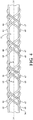
- winding angle or “wrap angle” includes the positive and negative measured fiber angles relative to the barrel's longitudinal axis. This is illustrated in Figure 4 , which shows a section of inner liner 22 in the initial stage of being wrapped with tow 34.
- tow 34 typically has a wide, flat profile. Its profile is “fattened” in Figure 4 to better illustrate tow placement.
- Tow 34 is helically wrapped around inner liner 22 as filament guide 44 translates laterally relative to rotating inner liner 22.
- the first lateral pass (left to right) winds a first tow segment 64.
- filament guide 44 When filament guide 44 completes its translation and reaches the end of inner liner 22, it reverses and helically winds the tow in the opposite direction, laying down second tow segment 65. The next pass winds third tow segment 66, and the next pass winds fourth tow segment 67.
- the winding angle for all four segments in Figure 4 is the same, albeit the angles alternate between positive and negative with each pass, measured relative to axial bore 24.
- angle ⁇ shown in Figure 4 with respect to first tow segment 64 is the "same wrapping angle" as ⁇ ' shown in Figure 4 with respect to fourth tow segment 67. In other words, the wrapping angle shown in Figure 4 is constant.
- Reference in the specification and the claims to "helical” means substantially helical, e.g., portions of inner liner 22 may not be strictly cylindrical.
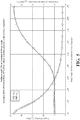
- Figure 5 also shows the effect of winding angle on linear CTE through the CFC.
- Lower winding angles i.e ., more axially aligned
- Near-perpendicular wrap angles have relatively high longitudinal CTE, about 27 ppm/ °C (15 ppm/°F).
- the CTE of inner liner 22 may vary considerably depending on composition.
- a ceramic or ceramic composite inner liner may have a CTE that is considerably less than steel.
- AISI 4140 steel has a CTE of approximately 12.2 ppm/ °C (6.8 ppm/°F).
- AISI 416 stainless steel has a CTE of approximately 9.99ppm/ °C (5.55 ppm/°F).
- the average effective longitudinal CTE of the CFC outer shell 20 will vary depending not only on wrap angle, but on a variety of other factors including matrix composition (e.g ., whether resin versus ceramic or metal, type of resin, etc.), presence of matrix additives such as thermally conductive heat dissipation additives, fiber type, tow tension during wrapping, regional wrap angle sequence, and regional wrap angle thicknesses. All of these factors must be considered when attempting to match the average effective longitudinal CTE of the CFC outer shell to the CTE of the steel liner. It is possible to design and fabricate a CFC outer shell having a desired average effective longitudinal CTE fabricated from materials other than unidirectional carbon fiber continuous tows, including for example textile composite prepreg carbon fiber, and carbon fiber braided sleeves. Noncarbon materials may also be used, such as ceramic, glass, mineral, polymer or metallic fibers, or mixtures thereof.
- the inventors have discovered that it is possible to match the average effective axial CTE of a CFC outer shell 20 to the CTE of an inner liner 22 by using a plurality of wrapping regions, while also providing excellent axial, radial, and torsional strength and stiffness, yet keeping bulk and weight at a minimum.
- CTE data and wrapping techniques familiar to those skilled in the art of fiber laminates, e.g. the relationships illustrated in Figure 5 , it is possible to engineer a laminate CFC outer shell 20 having good structural properties and a desired average effective CTE by wrapping a plurality of regions, each region having substantially the same winding angle and each having a radial thickness relative to the radial thickness of the CFC.
- CFC outer shell 20 surrounds and is in direct contact with inner liner 22.
- “surrounding the inner liner” means that outer shell 20 surrounds and is in direct contact with inner liner 22 along at least a portion of the axial length of barrel 14; parts of inner liner 22 may be exposed, for example, at muzzle 18, threads 16, a gas block (not shown), or any other desired location(s) on barrel 14.
- Outer shell 20 is structured in successive regions, with each region having substantially the same winding angle. The radial thickness of each region as a percentage of the CFC radius varies.
- inner liner 22 has a radial depth r s
- inner region 50 has a radial depth r 1
- first intermediate region 52 has a radial depth r 2
- second intermediate region 54 has radial depth r 3
- outer region 56 has radial depth r 4 .
- the sum of radial thicknesses of the regions in CFC outer shell 20 (r 1 + r 2 + r 3 + r 4 ) equal the radial thickness of CFC outer shell 20.
- the thickness of each region can be expressed as a percentage of the radial thickness of outer shell 20.
- Known classical laminate theory may be used to engineer a CFC outer shell 20 having a wide range of average effective longitudinal CTEs using a plurality of layered wrapping regions.
- the average effective CTE of the composite outer shell 20 is adjusted by varying the wrap angles of the plurality of regions, the regions' radial thicknesses, and the number and sequence of regions.
- the CTE may also be varied by changing the composition of resin/binder, the type of fiber, and the tension at which fiber tow 34 is wrapped on liner 22.
- one embodiment that approximately matches the CTE of type 416 stainless steel inner liner 22 with the CTE of CFC outer shell 20 comprises intermediate modulus PAN precursor carbon fibers and thermoset epoxy resin.
- This embodiment not only virtually eliminates thermal stresses due to CTE mismatch that can lead to deformation and displacement, but also provides superior performance, durability, with relatively low bulk and weight, at a commercially viable price for materials.
- Approximately matches for purposes of this specification and the claims means that the inner liner's longitudinal CTE is within 1.8 ppm/ °C (1 ppm/ °F) of the average effective longitudinal CTE associated with the CFC outer shell.
- a superior barrel design In addition to matching the average effective longitudinal CTE of outer shell 20 with inner liner 22, a superior barrel design also exhibits high axial strength and stiffness, low interlaminar shear stress during operation, and high hoop strength.
- Low angle plies e.g ., ⁇ 25°
- the further away a given mass of longitudinal plies is located from the steel liner the greater its contribution to axial stiffness.
- placing longitudinal low-angle plies on the outside of barrel 14 compromises durability, because they are more likely to delaminate or suffer interlaminar failure, such as when rubbed against a rough surface. Placing higher angle plies in the outer regions enhances durability.
- the outer shell 20 will have an axial stiffness of at least 5.5 Msi and a modulus in the radial plane (the radial plane containing angle ⁇ on Figure 7 ) of at least 10 Msi. Torsional strength and stiffness become more critical factors in medium and large caliber firearm barrels where the mass and diameter of the projectile become significant relative to the barrel outer diameter, imparting significant torsional force on the barrel.
- a 12K strand intermediate modulus PAN carbon fiber tow 34 is pulled through a wet epoxy thermoset resin mixture 36 at about five pounds tension, while it is being wound on type 416 stainless steel inner liner 22 rotating about its longitudinal axial bore 24.
- the resin mixture comprises 1.0% Thermalgraph® chopped carbon fiber pitch by weight of the resin mixture.
- Tow 34 is helically wound in a plurality of layered regions or "plies" extending radially outward from the liner surface, comprising an inner region 50, a plurality of intermediate regions, and an outer region 56.
- the tows within the inner region comprise circumferential hoops having a wrap angle of ⁇ 85° (all angles plus/minus about five degrees and measured relative to the barrel axis). At least one region has longitudinal helical wrap angles ⁇ 25°.
- interlaminar shear stress may arise between adjacent regions during operation because of heat, vibration, burst forces, and mismatched CTEs between regions, potentially leading to undesirable forces within the outer shell 20 or separation or delamination between adjacent regions.
- the inventors have determined that interlaminar stress is manageable if the angle wrap differential between adjacent regions is limited to less than 25°, and more preferably if the wrap angle differential is limited to approximately 20°.
- outer shell 20 comprises a plurality of layered regions, with an inner region 50 comprised of near-perpendicular circumferential hoops of intermediate modulus PAN precursor carbon fiber tow 34 wet-wrapped on inner liner 22 with a thermoset epoxy having a winding angle of ⁇ 85°, then a first intermediate region 52 having a winding angle of ⁇ 75°, then a second intermediate region 54 having a winding angle of ⁇ 65°, then a third intermediate region of ⁇ 45°, a fourth intermediate region of longitudinal helical wraps of ⁇ 25°, a fifth intermediate region of ⁇ 35°, and finally an outer region 56 having a wrap angle of ⁇ 45°. Any or all of these angles could be altered by plus/minus 5° and still provide comparable performance with a Type 416 stainless steel inner liner. Moreover, as mentioned previously, other types of carbon fiber, alone or in combination with PAN carbon fiber, could be used with similar results.
- Figure 7 shows an exemplar barrel 14 produced by the winding system described, comprising a CFC outer shell 20 progressively cut away to reveal a plurality of winding regions created by winding resin infused tow 42 (or heated towpreg 43) around inner liner 22.
- each region has a substantially different helical wrapping angle.
- Inner region 50 has a first wrapping angle 58
- first intermediate region 52 has a second wrapping angle 60
- second intermediate region 54 has a third wrapping angle 62.
- the number of regions may be any number, and the winding angles and depth of each layer may likewise vary.
- each region/ply affects the average effective CTE of the CFC outer shell.
- the regions described above vary significantly in radial thickness, expressed as a percentage of the radial distance from the surface of the steel inner liner 22 to the exterior surface of the finished outer shell 20.
- the regions have thicknesses as noted below, where the angle measurements are plus/minus 5°, and the percentage radial thickness are plus/minus 5%: region wrap angle thickness (% of CFC radius) inner ⁇ 85 40 ( ⁇ 5%) 1st intermediate ⁇ 75 7 ( ⁇ 5%) 2nd intermediate ⁇ 65 6 ( ⁇ 5%) 3d intermediate ⁇ 45 7 ( ⁇ 5%) 4th intermediate ⁇ 25 21 ( ⁇ 5%) 5th intermediate ⁇ 35 6 ( ⁇ 5%) outer ⁇ 45 13 ( ⁇ 5%)
- barrel 14 is then ground down to a desired diameter on a lathe, e.g. with diamond abrasives, then polished and finished as is known to those skilled in the art. It may then be attached to a receiver and stock, to an armored vehicle, fixed or portable shell launcher, etc.
- the fiber and wrapping techniques described herein can be employed with a wide variety of inner liner materials having various CTEs, including metals such as steel alloys as well as refractory materials, ceramics, and inner liners comprising a combination of the foregoing materials.
- the invention results in a lightweight, stiff, and strong barrel having greater burst strength than the prior art, thereby enabling thinner and lighter barrel liners.
- the finished barrel is durable, more resistant to laminar and interlaminar separation, and better withstands unpredictable behavior such as warping and/or separation at the CFC-steel interface due to matched CTEs.
Landscapes
- Engineering & Computer Science (AREA)
- General Engineering & Computer Science (AREA)
- Moulding By Coating Moulds (AREA)
Claims (15)
- Canon pour diriger la trajectoire d'un projectile déchargeable, comprenant :un revêtement intérieur (22) définissant un passage axial (24), le revêtement intérieur (22) présentant un coefficient d'expansion thermique (CTE) le long du passage axial (24) ; etune enveloppe extérieure (20) entourant le revêtement intérieur (22), et en contact direct avec celui-ci, l'enveloppe extérieure (20) étant fabriquée en fibre continue (34) dans une matrice créant un composite à base de fibres continues (CFC) présentant un CTE axial efficace moyen dans la direction axiale, l'enveloppe extérieure comprenant :a. une mèche de fibres (34) enroulée en hélice autour du revêtement intérieur (22), à un premier angle d'enroulement (θ) substantiellement constant pour former une zone interne (50) ;b. une mèche de fibres (34) enroulée en hélice autour de ladite zone interne (50) à un deuxième angle d'enroulement (θ) substantiellement constant se distinguant substantiellement du premier angle d'enroulement (θ) pour constituer une première zone intermédiaire (52) ;c. une mèche de fibres (34) enroulée en hélice autour de la précédente zone intermédiaire (52) à un angle d'enroulement substantiellement constant (θ) se distinguant substantiellement de l'angle d'enroulement (θ) caractérisant la précédente zone intermédiaire (52) ;d. une mèche de fibres (34) enroulée en hélice autour des précédentes zones intermédiaires (52) autant de fois qu'on le désire pour constituer de nouvelles zones intermédiaires (52) jusqu'à la formation d'une zone intermédiaire finale ; ete. une zone extérieure (56) comprenant une mèche de fibres (36) enroulée en hélice autour de la zone intermédiaire finale à un angle d'enroulement substantiellement constant (θ) se distinguant substantiellement de l'angle d'enroulement caractérisant la zone intermédiaire finale ;caractérisé en ce que le CTE axial efficace moyen de l'enveloppe extérieure (20) correspond approximativement au CTE axial du revêtement intérieur (22) de sorte que le CTE axial du revêtement intérieur (22) se situe à 1,8 ppm/ °C (1 ppm/ °F) du CTE axial efficace moyen de l'enveloppe extérieure (20), et les angles d'enroulement (θ) dans des zones adjacentes varient de moins de 25°.
- Canon selon la revendication 1, la matrice étant composée d'un matériau sélectionné parmi les suivants : polymère, métal, céramique, minéral, ou un allotrope du carbone.
- Canon selon la revendication 2, le CFC comprenant un mélange de résines (36) possédant un additif thermo-conducteur.
- Canon selon une quelconque des revendications 1 à 3, le revêtement intérieur (22) étant composé d'un matériau sélectionné entre une céramique ou un métal.
- Canon selon la revendication 4, le revêtement intérieur (22) étant un acier inoxydable du groupe 400 AISI, et le CTE axial efficace moyen de l'enveloppe extérieure (20) étant compris entre 8,1 et 11,7 ppm/ °C (4,5 et 6,5 ppm/°F).
- Canon selon la revendication 4, le revêtement intérieur (22) étant un acier allié du groupe 4000 AISI, et le CTE axial efficace moyen de l'enveloppe extérieure (20) étant compris entre 10,4 et 14 ppm/ °C (5,8 et 7,8 ppm/°F).
- Canon selon une quelconque des revendications 1 à 7, les fibres étant en carbone, céramique, verre, métal, minéral ou polymère.
- Canon selon la revendication 7, la mèche en fibres comprenant des fibres de carbone, et chaque zone stratifiée (50,52,54,56) présentant une épaisseur radiale (r2).
- Canon selon la revendication 8, au moins une desdites zones stratifiées (50,52,54,56) comprenant des fibres de carbone précurseur PAN.
- Canon selon la revendication 9, les fibres possédant un module d'élasticité dans la plage 265- 320 GPa.
- Canon selon une quelconque des revendications 8 à 10, au moins une desdites zones stratifiées (50,52,54,56) comprenant des fibres de carbone à précurseur à brai.
- Canon selon une quelconque des revendications 8 à 11, comprenant des zones ordonnées de la façon suivante :une zone interne (50) dont l'angle d'enroulement (θ) est compris entre ±80° et 90° et l'épaisseur radiale (r2) entre 35 % and 45 % de l'épaisseur radiale du CFC ;une première zone intermédiaire (52) dont l'angle d'enroulement (θ) est compris entre ±70° et 80° et l'épaisseur radiale (r2) entre 2 % et 12 % de l'épaisseur radiale du CFC ;une deuxième zone intermédiaire (54) dont l'angle d'enroulement (θ) est compris entre ±60° et 70° et l'épaisseur radiale (r2) entre 1 % et 11 % de l'épaisseur radiale du CFC ;une troisième zone intermédiaire dont l'angle d'enroulement (θ) est compris entre ±40° et 50° et l'épaisseur radiale entre 2 % et 12 % de l'épaisseur radiale du CFC ;une quatrième zone intermédiaire dont l'angle d'enroulement (θ) est compris entre ±20° et 30° et l'épaisseur radiale entre 16 % et 26 % de l'épaisseur radiale du CFC ;une cinquième zone intermédiaire dont l'angle d'enroulement (θ) est compris entre ±30° et 40° et l'épaisseur radiale entre 1 % et 11 % de l'épaisseur radiale du CFC ; etune zone extérieure (56) dont l'angle d'enroulement (θ) est compris entre ±40° et 50° et l'épaisseur radiale entre 8 % et 18 % de l'épaisseur radiale du CFC.
- Arme à feu (11) comprenant une culasse (12), une crosse raccordée à la culasse (12), et un canon (14) selon une quelconque des revendications 1 à 12 raccordé à la culasse (12), le revêtement intérieur (22) comprenant un revêtement intérieur métallique (22).
- Méthode de fabrication d'un canon (14) pour diriger la trajectoire d'un projectile déchargeable, comprenant les étapes suivantes :pourvoir un revêtement intérieur (22) définissant un passage axial (24), et présentant un coefficient axial d'expansion thermique (CTE) ;fabriquer une enveloppe extérieure (20) en composite à base de fibres continues (CFC) à régionalisation radiale autour du revêtement intérieur (22), l'enveloppe extérieure (20) possédant un CTE axial efficace moyen, ladite fabrication comprenant les étapes suivantes :a. enrouler en hélice d'une mèche de fibres (34) autour du revêtement intérieur (22) à un angle d'enroulement substantiellement constant (θ) pour constituer une zone interne (50) ;b. enrouler en hélice une mèche de fibres (34) autour de ladite zone interne (50) à un second angle d'enroulement substantiellement constant (θ) se distinguant substantiellement du premier angle d'enroulement (θ) pour constituer une première zone intermédiaire (52) ;c. enrouler en hélice une mèche de fibres (34) autour de la zone intermédiaire (52) précédente à un angle d'enroulement substantiellement constant (θ) se distinguant substantiellement de l'angle d'enroulement (θ) caractérisant la zone intermédiaire (52) précédente ;d. répéter l'étape c autant de fois qu'on le désire jusqu'à la formation d'une zone intermédiaire finale ;e. former une zone extérieure (56) par l'enroulement hélicoïdal de la mèche de fibres (36) autour de la zone intermédiaire finale à un angle d'enroulement substantiellement constant (θ) se distinguant substantiellement de l'angle d'enroulement caractérisant la zone intermédiaire finale ;la différence entre les angles d'enroulement (θ) dans des zones adjacentes étant inférieure à 25°, et le CTE axial du revêtement intérieur (22) se situant à 1,8 ppm/ °C (1 ppm/ °F) du CTE axial efficace moyen de l'enveloppe extérieure (20).
- Méthode selon la revendication 14, la mèche de fibres (34) comprenant une fibre de carbone précurseur PAN et/ou le revêtement intérieur (22) étant composé d'un alliage d'aciers inoxydables.
Applications Claiming Priority (2)
| Application Number | Priority Date | Filing Date | Title |
|---|---|---|---|
| US201361913825P | 2013-12-09 | 2013-12-09 | |
| PCT/US2014/069403 WO2015130379A2 (fr) | 2013-12-09 | 2014-12-09 | Système d'enroulement de fibre pour structure de type canon composite pour projectile |
Publications (3)
| Publication Number | Publication Date |
|---|---|
| EP3080543A2 EP3080543A2 (fr) | 2016-10-19 |
| EP3080543A4 EP3080543A4 (fr) | 2016-11-23 |
| EP3080543B1 true EP3080543B1 (fr) | 2018-09-05 |
Family
ID=54009751
Family Applications (1)
| Application Number | Title | Priority Date | Filing Date |
|---|---|---|---|
| EP14883548.1A Active EP3080543B1 (fr) | 2013-12-09 | 2014-12-09 | Système d'enroulement de fibre pour structure de type canon composite pour projectile |
Country Status (11)
| Country | Link |
|---|---|
| US (2) | US10168117B2 (fr) |
| EP (1) | EP3080543B1 (fr) |
| KR (1) | KR102313776B1 (fr) |
| CN (1) | CN105814396B (fr) |
| AU (1) | AU2014384616B2 (fr) |
| CA (1) | CA2933035C (fr) |
| DK (1) | DK3080543T3 (fr) |
| ES (1) | ES2700832T3 (fr) |
| IL (1) | IL246164B (fr) |
| WO (1) | WO2015130379A2 (fr) |
| ZA (1) | ZA201604583B (fr) |
Families Citing this family (21)
| Publication number | Priority date | Publication date | Assignee | Title |
|---|---|---|---|---|
| US9863732B2 (en) | 2013-08-28 | 2018-01-09 | Proof Research, Inc. | Lightweight composite mortar tube |
| US10953625B2 (en) * | 2014-01-23 | 2021-03-23 | Spartan Acquisition Llc | Unidirectional fiber composite system for structural repairs and reinforcement |
| US10597182B2 (en) | 2015-01-22 | 2020-03-24 | Neptune Research, Llc. | Composite reinforcement systems and methods of manufacturing the same |
| WO2016160308A1 (fr) * | 2015-03-11 | 2016-10-06 | Proof Research, Inc. | Tube de mortier composite léger |
| US9823034B2 (en) * | 2015-08-24 | 2017-11-21 | Dreadnought Technologies, Llc | System and method for improving performance of a weapon barrel |
| CN105442154B (zh) * | 2015-12-15 | 2017-05-10 | 机械科学研究总院先进制造技术研究中心 | 一种具有梯度结构的三维预制体织造方法 |
| US12061059B2 (en) | 2016-03-10 | 2024-08-13 | Consulting Group Of Jocassee, Inc. | Enhanced metal-metal-matrix composite weapon barrels |
| US20170261280A1 (en) * | 2016-03-10 | 2017-09-14 | Sapphire Defense Group LLC | Enhanced metal-metal-matrix composite weapon barrels and ways of making the same |
| KR101818845B1 (ko) * | 2016-03-24 | 2018-01-16 | (주)화이트스톤 | 발사체 유도관 |
| US11385013B2 (en) * | 2016-07-01 | 2022-07-12 | Blackpowder Products, Inc. | Hybrid carbon—steel firearm barrel |
| US10228209B2 (en) * | 2016-07-19 | 2019-03-12 | Cory J. Newman | Non-segmented composite barrel for gas operated firearms |
| US20180229092A1 (en) * | 2017-02-13 | 2018-08-16 | Cc3D Llc | Composite sporting equipment |
| RU2666505C1 (ru) * | 2017-07-04 | 2018-09-07 | Акционерное общество "Завод N 9" (АО "Завод N 9") | Танковая пушка |
| CN107702589A (zh) * | 2017-10-18 | 2018-02-16 | 中国人民解放军装甲兵工程学院 | 一种基于复合材料的轻量化火炮身管 |
| US11440287B2 (en) | 2018-06-07 | 2022-09-13 | Honeywell International Inc. | Hybrid fiber multi-axial prepreg |
| CN111070802A (zh) * | 2018-10-22 | 2020-04-28 | 有研工程技术研究院有限公司 | 一种复合结构身管及其成形方法 |
| CN111442693B (zh) * | 2020-04-22 | 2024-12-20 | 江苏恒神股份有限公司 | 基于碳纤维复合基材料的发射筒、制作方法 |
| USD1018757S1 (en) | 2020-09-17 | 2024-03-19 | Blackpowder Products, Inc. | Firearm barrel |
| AU2022200834B2 (en) * | 2021-02-17 | 2024-02-08 | Blackpowder Products, Inc. | Hybrid carbon - steel firearm barrel |
| CN113239549B (zh) * | 2021-05-18 | 2022-06-10 | 长沙理工大学 | 一种复合材料丝束缠绕工艺中非测地线缠绕路径设计方法 |
| CN118255204B (zh) * | 2024-05-30 | 2024-07-19 | 常州虹纬纺织有限公司 | 一种细旦化学纤维缝纫线的加工设备 |
Family Cites Families (28)
| Publication number | Priority date | Publication date | Assignee | Title |
|---|---|---|---|---|
| US2847786A (en) | 1955-02-07 | 1958-08-19 | Olin Mathieson | Composite firearm barrel comprising glass fibers |
| US2845741A (en) | 1955-04-27 | 1958-08-05 | Olin Mathieson | Composite firearm barrel |
| US3517585A (en) | 1966-03-10 | 1970-06-30 | Edwin Slade | Reinforced plastic tube and gun barrel construction incorporating an imbedded expandable woven screen lining |
| US3879244A (en) | 1973-04-18 | 1975-04-22 | Us Air Force | Method of making high modulus graphite fiber reinforced tubes |
| US4435455A (en) * | 1983-01-10 | 1984-03-06 | United Technologies Corporation | Compliant composite tubular liners of fiber reinforced glass/glass-ceramic having utility as gun barrel liners |
| US4685236A (en) * | 1984-05-30 | 1987-08-11 | Sam May | Graphite/metal matrix gun barrel |
| US4669212A (en) * | 1984-10-29 | 1987-06-02 | General Electric Company | Gun barrel for use at high temperature |
| US5125179A (en) | 1991-04-08 | 1992-06-30 | The United States Of America As Represented By The Secretary Of The Air Force | Nonmetallic tubular structure |
| FR2677442B1 (fr) | 1991-06-06 | 1993-10-15 | Propulsion Ste Europeenne | Chemise de tube de canon en materiau composite, son procede de fabrication, et tube de canon muni d'une telle chemise. |
| US5341719A (en) | 1992-12-14 | 1994-08-30 | General Electric Company | Multi-layer composite gun barrel |
| US5600912A (en) | 1995-11-29 | 1997-02-11 | Smith; David B. | Composite tube for a gun barrel |
| US5804756A (en) * | 1995-12-18 | 1998-09-08 | Rjc Development, L.C. | Composite/metallic gun barrel having matched coefficients of thermal expansion |
| US5692334A (en) | 1995-12-18 | 1997-12-02 | Roland J. Christensen Family Limited Partnership | Primarily independent composite/metallic gun barrel |
| US5657568A (en) | 1995-12-18 | 1997-08-19 | Roland J. Christensen | Composite/metallic gun barrel having a differing, restrictive coefficient of thermal expansion |
| WO1997022843A1 (fr) * | 1995-12-18 | 1997-06-26 | Roland Christensen | Canon de fusil composite/metallique ameliore |
| US6189431B1 (en) | 1998-01-26 | 2001-02-20 | Remington Arms Company, Inc. | Small caliber gun barrel |
| US7153465B1 (en) * | 2001-08-14 | 2006-12-26 | Thor Technologies, Inc. | Method of producing hybrid tubular metal/ceramic composites |
| US6889464B2 (en) | 2003-06-04 | 2005-05-10 | Michael K. Degerness | Composite structural member |
| JP2005155935A (ja) | 2003-11-20 | 2005-06-16 | Tech Res & Dev Inst Of Japan Def Agency | 円管構造体 |
| US8079945B2 (en) * | 2004-02-10 | 2011-12-20 | Pactiv Corporation | Fiber-reinforced film processes and films |
| PL1740899T3 (pl) * | 2004-04-27 | 2013-05-31 | Materials And Electrochemical Res Corporation | Lufa broni i sposób wytwarzania |
| US7775200B2 (en) * | 2005-05-23 | 2010-08-17 | Anderson Kenneth K | Barrel system for a paintball marker |
| US7934332B2 (en) * | 2006-02-23 | 2011-05-03 | Sturm, Ruger & Company, Inc. | Composite firearm barrel |
| CN101835830B (zh) | 2007-08-31 | 2013-02-20 | 卡伯特公司 | 热界面材料 |
| GB2453308B (en) * | 2007-10-03 | 2012-07-25 | Acell Group Ltd | Composite products |
| US9863732B2 (en) * | 2013-08-28 | 2018-01-09 | Proof Research, Inc. | Lightweight composite mortar tube |
| ES2719826T3 (es) | 2013-08-28 | 2019-07-16 | Proof Res Inc | Cañón de proyectil compuesto de alta temperatura |
| JP6889464B2 (ja) | 2016-12-07 | 2021-06-18 | 国立大学法人電気通信大学 | チャットシステム、管理装置、端末装置、宛先選択支援方法および宛先選択支援プログラム |
-
2014
- 2014-12-09 EP EP14883548.1A patent/EP3080543B1/fr active Active
- 2014-12-09 KR KR1020167017374A patent/KR102313776B1/ko active Active
- 2014-12-09 WO PCT/US2014/069403 patent/WO2015130379A2/fr not_active Ceased
- 2014-12-09 DK DK14883548.1T patent/DK3080543T3/en active
- 2014-12-09 ES ES14883548T patent/ES2700832T3/es active Active
- 2014-12-09 AU AU2014384616A patent/AU2014384616B2/en active Active
- 2014-12-09 CN CN201480067261.3A patent/CN105814396B/zh active Active
- 2014-12-09 US US15/102,830 patent/US10168117B2/en active Active
- 2014-12-09 US US15/177,976 patent/US20160334180A1/en not_active Abandoned
- 2014-12-09 CA CA2933035A patent/CA2933035C/fr active Active
-
2016
- 2016-06-09 IL IL246164A patent/IL246164B/en active IP Right Grant
- 2016-07-06 ZA ZA2016/04583A patent/ZA201604583B/en unknown
Non-Patent Citations (1)
| Title |
|---|
| None * |
Also Published As
| Publication number | Publication date |
|---|---|
| IL246164A0 (en) | 2016-07-31 |
| IL246164B (en) | 2021-02-28 |
| CN105814396B (zh) | 2018-04-24 |
| WO2015130379A3 (fr) | 2015-10-22 |
| WO2015130379A2 (fr) | 2015-09-03 |
| EP3080543A4 (fr) | 2016-11-23 |
| AU2014384616B2 (en) | 2019-11-14 |
| US10168117B2 (en) | 2019-01-01 |
| ES2700832T3 (es) | 2019-02-19 |
| US20160334180A1 (en) | 2016-11-17 |
| CA2933035C (fr) | 2018-03-13 |
| DK3080543T3 (en) | 2019-01-07 |
| US20160320156A1 (en) | 2016-11-03 |
| CA2933035A1 (fr) | 2015-09-03 |
| ZA201604583B (en) | 2018-11-28 |
| NZ720293A (en) | 2020-09-25 |
| AU2014384616A1 (en) | 2016-06-09 |
| KR20160104626A (ko) | 2016-09-05 |
| EP3080543A2 (fr) | 2016-10-19 |
| KR102313776B1 (ko) | 2021-10-15 |
| CN105814396A (zh) | 2016-07-27 |
Similar Documents
| Publication | Publication Date | Title |
|---|---|---|
| EP3080543B1 (fr) | Système d'enroulement de fibre pour structure de type canon composite pour projectile | |
| US9863732B2 (en) | Lightweight composite mortar tube | |
| US10001337B2 (en) | Composite multi-lobe projectile barrel | |
| US6889464B2 (en) | Composite structural member | |
| US10161700B2 (en) | Cooling of weapons with graphite foam | |
| US20160363402A1 (en) | Systems and methods for composite gun barrel | |
| US11385013B2 (en) | Hybrid carbon—steel firearm barrel | |
| EP3039374B1 (fr) | Fût de projectile composite à haute température | |
| US5657568A (en) | Composite/metallic gun barrel having a differing, restrictive coefficient of thermal expansion | |
| US20180017350A1 (en) | Composite projectile barrel | |
| EP4047300A1 (fr) | Barillet pour arme à feu hybride carbone-acier | |
| WO2016160308A1 (fr) | Tube de mortier composite léger | |
| NZ720293B2 (en) | Fiber winding system for composite projectile barrel structure | |
| CA3234493A1 (fr) | Article multicouche comprenant un metal, un hybride thermoconducteur et un composite de fibres continues thermoconductrices |
Legal Events
| Date | Code | Title | Description |
|---|---|---|---|
| PUAI | Public reference made under article 153(3) epc to a published international application that has entered the european phase |
Free format text: ORIGINAL CODE: 0009012 |
|
| 17P | Request for examination filed |
Effective date: 20160607 |
|
| AK | Designated contracting states |
Kind code of ref document: A2 Designated state(s): AL AT BE BG CH CY CZ DE DK EE ES FI FR GB GR HR HU IE IS IT LI LT LU LV MC MK MT NL NO PL PT RO RS SE SI SK SM TR |
|
| AX | Request for extension of the european patent |
Extension state: BA ME |
|
| STAA | Information on the status of an ep patent application or granted ep patent |
Free format text: STATUS: EXAMINATION IS IN PROGRESS |
|
| A4 | Supplementary search report drawn up and despatched |
Effective date: 20161024 |
|
| RIC1 | Information provided on ipc code assigned before grant |
Ipc: F41A 21/02 20060101AFI20161018BHEP |
|
| 17Q | First examination report despatched |
Effective date: 20161111 |
|
| DAX | Request for extension of the european patent (deleted) | ||
| GRAP | Despatch of communication of intention to grant a patent |
Free format text: ORIGINAL CODE: EPIDOSNIGR1 |
|
| STAA | Information on the status of an ep patent application or granted ep patent |
Free format text: STATUS: GRANT OF PATENT IS INTENDED |
|
| INTG | Intention to grant announced |
Effective date: 20180620 |
|
| GRAS | Grant fee paid |
Free format text: ORIGINAL CODE: EPIDOSNIGR3 |
|
| GRAA | (expected) grant |
Free format text: ORIGINAL CODE: 0009210 |
|
| STAA | Information on the status of an ep patent application or granted ep patent |
Free format text: STATUS: THE PATENT HAS BEEN GRANTED |
|
| AK | Designated contracting states |
Kind code of ref document: B1 Designated state(s): AL AT BE BG CH CY CZ DE DK EE ES FI FR GB GR HR HU IE IS IT LI LT LU LV MC MK MT NL NO PL PT RO RS SE SI SK SM TR |
|
| REG | Reference to a national code |
Ref country code: GB Ref legal event code: FG4D |
|
| REG | Reference to a national code |
Ref country code: CH Ref legal event code: EP |
|
| REG | Reference to a national code |
Ref country code: AT Ref legal event code: REF Ref document number: 1038325 Country of ref document: AT Kind code of ref document: T Effective date: 20180915 |
|
| REG | Reference to a national code |
Ref country code: IE Ref legal event code: FG4D |
|
| REG | Reference to a national code |
Ref country code: DE Ref legal event code: R096 Ref document number: 602014032078 Country of ref document: DE |
|
| REG | Reference to a national code |
Ref country code: NL Ref legal event code: FP |
|
| REG | Reference to a national code |
Ref country code: DK Ref legal event code: T3 Effective date: 20190103 |
|
| REG | Reference to a national code |
Ref country code: SE Ref legal event code: TRGR |
|
| REG | Reference to a national code |
Ref country code: LT Ref legal event code: MG4D |
|
| PG25 | Lapsed in a contracting state [announced via postgrant information from national office to epo] |
Ref country code: LT Free format text: LAPSE BECAUSE OF FAILURE TO SUBMIT A TRANSLATION OF THE DESCRIPTION OR TO PAY THE FEE WITHIN THE PRESCRIBED TIME-LIMIT Effective date: 20180905 Ref country code: BG Free format text: LAPSE BECAUSE OF FAILURE TO SUBMIT A TRANSLATION OF THE DESCRIPTION OR TO PAY THE FEE WITHIN THE PRESCRIBED TIME-LIMIT Effective date: 20181205 Ref country code: GR Free format text: LAPSE BECAUSE OF FAILURE TO SUBMIT A TRANSLATION OF THE DESCRIPTION OR TO PAY THE FEE WITHIN THE PRESCRIBED TIME-LIMIT Effective date: 20181206 Ref country code: RS Free format text: LAPSE BECAUSE OF FAILURE TO SUBMIT A TRANSLATION OF THE DESCRIPTION OR TO PAY THE FEE WITHIN THE PRESCRIBED TIME-LIMIT Effective date: 20180905 |
|
| REG | Reference to a national code |
Ref country code: NO Ref legal event code: T2 Effective date: 20180905 |
|
| REG | Reference to a national code |
Ref country code: ES Ref legal event code: FG2A Ref document number: 2700832 Country of ref document: ES Kind code of ref document: T3 Effective date: 20190219 |
|
| PG25 | Lapsed in a contracting state [announced via postgrant information from national office to epo] |
Ref country code: HR Free format text: LAPSE BECAUSE OF FAILURE TO SUBMIT A TRANSLATION OF THE DESCRIPTION OR TO PAY THE FEE WITHIN THE PRESCRIBED TIME-LIMIT Effective date: 20180905 Ref country code: LV Free format text: LAPSE BECAUSE OF FAILURE TO SUBMIT A TRANSLATION OF THE DESCRIPTION OR TO PAY THE FEE WITHIN THE PRESCRIBED TIME-LIMIT Effective date: 20180905 Ref country code: AL Free format text: LAPSE BECAUSE OF FAILURE TO SUBMIT A TRANSLATION OF THE DESCRIPTION OR TO PAY THE FEE WITHIN THE PRESCRIBED TIME-LIMIT Effective date: 20180905 |
|
| PG25 | Lapsed in a contracting state [announced via postgrant information from national office to epo] |
Ref country code: RO Free format text: LAPSE BECAUSE OF FAILURE TO SUBMIT A TRANSLATION OF THE DESCRIPTION OR TO PAY THE FEE WITHIN THE PRESCRIBED TIME-LIMIT Effective date: 20180905 Ref country code: EE Free format text: LAPSE BECAUSE OF FAILURE TO SUBMIT A TRANSLATION OF THE DESCRIPTION OR TO PAY THE FEE WITHIN THE PRESCRIBED TIME-LIMIT Effective date: 20180905 Ref country code: IS Free format text: LAPSE BECAUSE OF FAILURE TO SUBMIT A TRANSLATION OF THE DESCRIPTION OR TO PAY THE FEE WITHIN THE PRESCRIBED TIME-LIMIT Effective date: 20190105 Ref country code: PL Free format text: LAPSE BECAUSE OF FAILURE TO SUBMIT A TRANSLATION OF THE DESCRIPTION OR TO PAY THE FEE WITHIN THE PRESCRIBED TIME-LIMIT Effective date: 20180905 |
|
| PG25 | Lapsed in a contracting state [announced via postgrant information from national office to epo] |
Ref country code: PT Free format text: LAPSE BECAUSE OF FAILURE TO SUBMIT A TRANSLATION OF THE DESCRIPTION OR TO PAY THE FEE WITHIN THE PRESCRIBED TIME-LIMIT Effective date: 20190105 Ref country code: SM Free format text: LAPSE BECAUSE OF FAILURE TO SUBMIT A TRANSLATION OF THE DESCRIPTION OR TO PAY THE FEE WITHIN THE PRESCRIBED TIME-LIMIT Effective date: 20180905 Ref country code: SK Free format text: LAPSE BECAUSE OF FAILURE TO SUBMIT A TRANSLATION OF THE DESCRIPTION OR TO PAY THE FEE WITHIN THE PRESCRIBED TIME-LIMIT Effective date: 20180905 |
|
| REG | Reference to a national code |
Ref country code: DE Ref legal event code: R097 Ref document number: 602014032078 Country of ref document: DE |
|
| PLBE | No opposition filed within time limit |
Free format text: ORIGINAL CODE: 0009261 |
|
| STAA | Information on the status of an ep patent application or granted ep patent |
Free format text: STATUS: NO OPPOSITION FILED WITHIN TIME LIMIT |
|
| REG | Reference to a national code |
Ref country code: CH Ref legal event code: PL |
|
| 26N | No opposition filed |
Effective date: 20190606 |
|
| PG25 | Lapsed in a contracting state [announced via postgrant information from national office to epo] |
Ref country code: SI Free format text: LAPSE BECAUSE OF FAILURE TO SUBMIT A TRANSLATION OF THE DESCRIPTION OR TO PAY THE FEE WITHIN THE PRESCRIBED TIME-LIMIT Effective date: 20180905 Ref country code: LU Free format text: LAPSE BECAUSE OF NON-PAYMENT OF DUE FEES Effective date: 20181209 Ref country code: MC Free format text: LAPSE BECAUSE OF FAILURE TO SUBMIT A TRANSLATION OF THE DESCRIPTION OR TO PAY THE FEE WITHIN THE PRESCRIBED TIME-LIMIT Effective date: 20180905 |
|
| REG | Reference to a national code |
Ref country code: IE Ref legal event code: MM4A |
|
| REG | Reference to a national code |
Ref country code: BE Ref legal event code: MM Effective date: 20181231 |
|
| PG25 | Lapsed in a contracting state [announced via postgrant information from national office to epo] |
Ref country code: IE Free format text: LAPSE BECAUSE OF NON-PAYMENT OF DUE FEES Effective date: 20181209 |
|
| PG25 | Lapsed in a contracting state [announced via postgrant information from national office to epo] |
Ref country code: BE Free format text: LAPSE BECAUSE OF NON-PAYMENT OF DUE FEES Effective date: 20181231 |
|
| PG25 | Lapsed in a contracting state [announced via postgrant information from national office to epo] |
Ref country code: LI Free format text: LAPSE BECAUSE OF NON-PAYMENT OF DUE FEES Effective date: 20181231 Ref country code: CH Free format text: LAPSE BECAUSE OF NON-PAYMENT OF DUE FEES Effective date: 20181231 |
|
| PG25 | Lapsed in a contracting state [announced via postgrant information from national office to epo] |
Ref country code: MT Free format text: LAPSE BECAUSE OF NON-PAYMENT OF DUE FEES Effective date: 20181209 |
|
| PG25 | Lapsed in a contracting state [announced via postgrant information from national office to epo] |
Ref country code: MK Free format text: LAPSE BECAUSE OF NON-PAYMENT OF DUE FEES Effective date: 20180905 Ref country code: HU Free format text: LAPSE BECAUSE OF FAILURE TO SUBMIT A TRANSLATION OF THE DESCRIPTION OR TO PAY THE FEE WITHIN THE PRESCRIBED TIME-LIMIT; INVALID AB INITIO Effective date: 20141209 Ref country code: CY Free format text: LAPSE BECAUSE OF FAILURE TO SUBMIT A TRANSLATION OF THE DESCRIPTION OR TO PAY THE FEE WITHIN THE PRESCRIBED TIME-LIMIT Effective date: 20180905 |
|
| REG | Reference to a national code |
Ref country code: AT Ref legal event code: UEP Ref document number: 1038325 Country of ref document: AT Kind code of ref document: T Effective date: 20180905 |
|
| PGFP | Annual fee paid to national office [announced via postgrant information from national office to epo] |
Ref country code: GB Payment date: 20251224 Year of fee payment: 12 |
|
| PGFP | Annual fee paid to national office [announced via postgrant information from national office to epo] |
Ref country code: AT Payment date: 20251230 Year of fee payment: 12 |
|
| PGFP | Annual fee paid to national office [announced via postgrant information from national office to epo] |
Ref country code: FI Payment date: 20251230 Year of fee payment: 12 Ref country code: DK Payment date: 20251230 Year of fee payment: 12 |
|
| PGFP | Annual fee paid to national office [announced via postgrant information from national office to epo] |
Ref country code: NL Payment date: 20251229 Year of fee payment: 12 Ref country code: FR Payment date: 20251229 Year of fee payment: 12 |
|
| PGFP | Annual fee paid to national office [announced via postgrant information from national office to epo] |
Ref country code: TR Payment date: 20251130 Year of fee payment: 12 |
|
| PGFP | Annual fee paid to national office [announced via postgrant information from national office to epo] |
Ref country code: SE Payment date: 20251230 Year of fee payment: 12 |
|
| PGFP | Annual fee paid to national office [announced via postgrant information from national office to epo] |
Ref country code: CZ Payment date: 20251205 Year of fee payment: 12 |
|
| PGFP | Annual fee paid to national office [announced via postgrant information from national office to epo] |
Ref country code: ES Payment date: 20260114 Year of fee payment: 12 |
|
| PGFP | Annual fee paid to national office [announced via postgrant information from national office to epo] |
Ref country code: DE Payment date: 20251230 Year of fee payment: 12 Ref country code: NO Payment date: 20251231 Year of fee payment: 12 |
|
| PGFP | Annual fee paid to national office [announced via postgrant information from national office to epo] |
Ref country code: IT Payment date: 20251229 Year of fee payment: 12 |