EP3080558B1 - Verfahren und werkzeug zur ölquellenmessung mit impulswellen-ultraschall - Google Patents
Verfahren und werkzeug zur ölquellenmessung mit impulswellen-ultraschall Download PDFInfo
- Publication number
- EP3080558B1 EP3080558B1 EP13818026.0A EP13818026A EP3080558B1 EP 3080558 B1 EP3080558 B1 EP 3080558B1 EP 13818026 A EP13818026 A EP 13818026A EP 3080558 B1 EP3080558 B1 EP 3080558B1
- Authority
- EP
- European Patent Office
- Prior art keywords
- ultrasound
- doppler
- tubing
- signals
- module
- Prior art date
- Legal status (The legal status is an assumption and is not a legal conclusion. Google has not performed a legal analysis and makes no representation as to the accuracy of the status listed.)
- Active
Links
Images




Classifications
-
- G—PHYSICS
- G01—MEASURING; TESTING
- G01F—MEASURING VOLUME, VOLUME FLOW, MASS FLOW OR LIQUID LEVEL; METERING BY VOLUME
- G01F1/00—Measuring the volume flow or mass flow of fluid or fluent solid material wherein the fluid passes through a meter in a continuous flow
- G01F1/66—Measuring the volume flow or mass flow of fluid or fluent solid material wherein the fluid passes through a meter in a continuous flow by measuring frequency, phase shift or propagation time of electromagnetic or other waves, e.g. using ultrasonic flowmeters
- G01F1/663—Measuring the volume flow or mass flow of fluid or fluent solid material wherein the fluid passes through a meter in a continuous flow by measuring frequency, phase shift or propagation time of electromagnetic or other waves, e.g. using ultrasonic flowmeters by measuring Doppler frequency shift
-
- E—FIXED CONSTRUCTIONS
- E21—EARTH OR ROCK DRILLING; MINING
- E21B—EARTH OR ROCK DRILLING; OBTAINING OIL, GAS, WATER, SOLUBLE OR MELTABLE MATERIALS OR A SLURRY OF MINERALS FROM WELLS
- E21B47/00—Survey of boreholes or wells
- E21B47/10—Locating fluid leaks, intrusions or movements
- E21B47/107—Locating fluid leaks, intrusions or movements using acoustic means
-
- E—FIXED CONSTRUCTIONS
- E21—EARTH OR ROCK DRILLING; MINING
- E21B—EARTH OR ROCK DRILLING; OBTAINING OIL, GAS, WATER, SOLUBLE OR MELTABLE MATERIALS OR A SLURRY OF MINERALS FROM WELLS
- E21B47/00—Survey of boreholes or wells
- E21B47/12—Means for transmitting measuring-signals or control signals from the well to the surface, or from the surface to the well, e.g. for logging while drilling
- E21B47/14—Means for transmitting measuring-signals or control signals from the well to the surface, or from the surface to the well, e.g. for logging while drilling using acoustic waves
- E21B47/16—Means for transmitting measuring-signals or control signals from the well to the surface, or from the surface to the well, e.g. for logging while drilling using acoustic waves through the drill string or casing, e.g. by torsional acoustic waves
-
- G—PHYSICS
- G01—MEASURING; TESTING
- G01N—INVESTIGATING OR ANALYSING MATERIALS BY DETERMINING THEIR CHEMICAL OR PHYSICAL PROPERTIES
- G01N29/00—Investigating or analysing materials by the use of ultrasonic, sonic or infrasonic waves; Visualisation of the interior of objects by transmitting ultrasonic or sonic waves through the object
- G01N29/04—Analysing solids
- G01N29/06—Visualisation of the interior, e.g. acoustic microscopy
- G01N29/0654—Imaging
-
- G—PHYSICS
- G01—MEASURING; TESTING
- G01N—INVESTIGATING OR ANALYSING MATERIALS BY DETERMINING THEIR CHEMICAL OR PHYSICAL PROPERTIES
- G01N29/00—Investigating or analysing materials by the use of ultrasonic, sonic or infrasonic waves; Visualisation of the interior of objects by transmitting ultrasonic or sonic waves through the object
- G01N29/22—Details, e.g. general constructional or apparatus details
- G01N29/225—Supports, positioning or alignment in moving situation
-
- G—PHYSICS
- G01—MEASURING; TESTING
- G01N—INVESTIGATING OR ANALYSING MATERIALS BY DETERMINING THEIR CHEMICAL OR PHYSICAL PROPERTIES
- G01N29/00—Investigating or analysing materials by the use of ultrasonic, sonic or infrasonic waves; Visualisation of the interior of objects by transmitting ultrasonic or sonic waves through the object
- G01N29/22—Details, e.g. general constructional or apparatus details
- G01N29/26—Arrangements for orientation or scanning by relative movement of the head and the sensor
- G01N29/262—Arrangements for orientation or scanning by relative movement of the head and the sensor by electronic orientation or focusing, e.g. with phased arrays
-
- G—PHYSICS
- G01—MEASURING; TESTING
- G01N—INVESTIGATING OR ANALYSING MATERIALS BY DETERMINING THEIR CHEMICAL OR PHYSICAL PROPERTIES
- G01N2291/00—Indexing codes associated with group G01N29/00
- G01N2291/10—Number of transducers
- G01N2291/106—Number of transducers one or more transducer arrays
-
- G—PHYSICS
- G01—MEASURING; TESTING
- G01N—INVESTIGATING OR ANALYSING MATERIALS BY DETERMINING THEIR CHEMICAL OR PHYSICAL PROPERTIES
- G01N2291/00—Indexing codes associated with group G01N29/00
- G01N2291/26—Scanned objects
- G01N2291/263—Surfaces
- G01N2291/2636—Surfaces cylindrical from inside
Definitions
- the present invention is a combined ultrasound imaging and Doppler wireline logging sonde tool. More specifically the present invention is a wireline logging apparatus serving a dual purpose: A first purpose is ultrasound imaging of the production pipe wall in a petroleum production well or the like. A second purpose is conducting Doppler measurements of flow velocities of fluids in the well, particularly for measuring flow velocities in the annulus fluid surrounding the production pipe. The logging sonde may be controlled from the surface to switch between the above operation modes.
- US4947683 Minear et al. "Pulsed ultrasonic Doppler borehole fluid measuring apparatus", published 14.08.1990, describes a logging sonde for use in a producing well, including centralizers to center the sonde to make an annular flow around it within the producing channel.
- the logging sonde comprises an ultrasonic transmitter/receiver which is mounted at the lower portion of the sonde for transmitting downwards and with an angle off the vertical axis of the sonde and the borehole, please see its Fig. 2 .
- the transmitter/receiver mount is rotated about the vertical axis of the sonde in order for the transmitter / receiver to sweep out a conical surface through the upwelling fluid in the borehole.
- Material inhomogeneities such as gas bubbles form reflective interfaces in the fluid flow which scatter ultrasonic pulses so that a return pulse is formed.
- the transmitter transmits short ultrasound bursts at a repetition rate, and has several time gates for receiving backscattered reflections from gas bubbles, sediment particles or droplets in the relevant distance range within the production fluid flow. Doppler shift in the return pulses due to the inclusions' vertical velocities are measured, thus the fluid flow velocity is found.
- Downhole Doppler flowmeter is a device for measuring the upward flow velocity in a borehole. It has a similar obliquely-arranged set of transmitter and receiver as for US4947683 above, but with the transmitter and receiver arranged not at the lower end but at the lateral face of the sonde, please see its Fig. 1 , thus measuring the annulus flow past the logging sonde. In order to correct for the local borehole diameter's effect on the annulus flow velocity past the sonde which is in the flow itself, and not in an annulus around any pipe, diameter measurements from a caliper logging device on the sonde are included for correcting the Doppler shift measured velocity to obtain the actual upward flow velocity in the borehole.
- US-patent US3603145 published 07.09.1971 describes a method of monitoring fluids and flow in a borehole, comprising using a wireline logging sonde with an ultrasound transducer of predetermined frequency and with downstream and upstream acoustic receivers at known distances above and below, for measuring frequency shifts and thereby detecting upstream and downstream acoustic (sound) velocities.
- the difference between the upstream and downstream acoustic velocities gives a fluid flow velocity of the fluid past the sonde.
- the upstream and downstream sound velocities are related to fluid density.
- the acoustic velocity depends on density, and in the cited US-patent only the fluid flow velocities and the fluid acoustic velocities are sought, the acoustic signals propagating through the borehole wall and through the rocks must be discriminated.
- prior art document describes devices for directing the acoustic energy primarily through the fluid column in the borehole. Further, the document describes attenuators for reducing the signal transmission through the borehole wall.
- the acoustic measurement signals are passed through the wireline to the surface. At the surface the acoustic measurement signal are read out on a surface read-out unit reading the measurements from a signal transmission such as brushes on the wireline drum.
- the acoustic measurements received on the surface read-out unit are correlated with readings from a wireline logging depth measuring sheave at the surface, and recorded.
- a further transducer assembly for use in monitoring systems in boreholes in connection with oil and/or gas exploration and/or extraction is disclosed in WO2010/151136 A1 .
- the invention concerns a pulse-wave ultrasound production well tubing wireline logging method using a logging tool (0) communicating via a wireline to a surface read-out unit,
- the main purpose of the present invention is to use ultrasound pulse-wave Doppler measurements to detect and measure flow in a petroleum well such as a production well, injection well, or the like, particularly flow in a tubing annulus or casing annulus. Flow in the tubing annulus or casing annulus may be due to leaks and are undesired and the present tool is capable of detecting and measure such flow.
- Another purpose is ultrasound pulse-wave imaging of the production pipe wall in a petroleum production well, an injection well, or the like.
- the tool of the invention is for conducting ultrasound pulse-wave Doppler measurements to detect and measure the flow of the fluids in the annulus surrounding the production pipe, and possibly also fluid flow velocities in further annuli such as outside the casing pipe.
- the Doppler measurements may be corrected for flow within the tubing.
- the Doppler measurements may also be corrected for clutter due to the tool's own movement, please see below.
- the production fluid and the annulus fluid may be oil, water or gas or a mixture of those, and may contain particles such as sand, or inhomogeneities.
- the production pipe annulus and the further annuli may be void and thus only fluid filled, and the casing annulus, if a casing is present, may be gravel packed, or cemented, but still permeable for fluids and subject to undesired leaks.
- the logging tool may be used for switching between logging for detecting undesired leaks in the well, for ultrasound imaging of the production tubing's inner surface, wall thickness and outer surface to detect pitting, cracks or holes or other irregularities, and for measuring fluid flow velocities in the production pipe annulus or the casing annulus.
- Doppler measurements within the production pipe may be used for correcting for the Doppler measurements in the production annulus, but other velocity measurements within the production pipe may serve the same purpose.
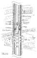
- Fig. 1 is a highly simplified vertical section illustration of part of a completed petroleum well with a cemented casing in a borehole through overlying rocks to an influx zone in a reservoir formation.
- a first fluid (F1) flows in the production tubing and a second fluid (F2) is present in the annulus space (7).
- An ultrasound logging tool of the invention is arranged within the production tubing.
- the ultrasound logging tool of the invention has a frustoconical-shaped linear, ring-shaped ultrasound transducer array (04) of ultrasound transducer elements (041).
- the transducer array (04) is covered by an ultrasound transparent window around the ring-shaped ultrasound transducer array (04).
- the transducer array is arranged in a lower portion (013) near the lower end of a main housing (01).
- the number of transducer elements may not necessarily be 288, but for the present prototype embodiment this provided the possibility of selecting a high number of consecutive transducer elements (041) to be selected among the 288 at a time, for beamforming a transmitted ultrasound beam A (and its opposite beam B) with high azimuthal resolution. Further, the transmitting surface (042) of each of the 288 transducer elements (041) will cover about 1 degree azimuthally.
- Each transducer element's (041) transducer surface's (042) width is less than 1/2 of the wavelength, which will have an approximately spherical transmission which is required for beamforming through interference from several transducer elements.
- the number (m) of elements in said ring-shaped ultrasound transducer (04) may between 64 and 512 depending on the required azimuthal resolution and the wavelength.
- the emitted ultrasound frequency of the pulse wave is in the range 1 to 5 MHz, preferably about 3 MHz. Particularly Doppler measurements may use down to 1 MHz.
- Centralizers may be arranged below the transducer array and also further up along the main housing (01), please see Fig. 1 .
- the ultrasound tool is arranged for operating on a common toolbus with other logging tools in a logging tool string, please see Fig. 9 , Fig. 10a and Fig. 10b .
- the ultrasound tool of the invention produces high-density ultrasound data at a high bit rate, the high bit rate exceeding the global bit rate on an ordinary toolbus usually connecting all tool sections with a telemetry server connected to a signal cable to a surface read-out unit, and certainly the telemetry bit rate at the signal cable itself, which is the main limiting bit rate factor.
- the ultrasound tool according to the invention is in a preferred embodiment connectable to a dedicated high capacity memory tool section ("02") connected immediately above the main housing (01).
- the ultrasound tool of the invention is arranged for being controlled from the surface and send low-resolution images to the surface via the common telemetry line and the ordinary toolbus while logging, and in the preferred embodiment for using the dedicated memory tool as a buffer for the high-resolution data produced.
- the dedicated memory tool may then be polled from the surface read-out unit for part of or all of the high-resolution data when capacity on the telemetry line is available.
- Fig. 2 is a highly simplified illustration of a vertical section through the mechanical structure of the ultrasound logging tool of the invention.
- a connector to the above tools in a toolstring.
- the connector particularly has, in addition to the common power line and the toolstring-common toolbus, also connectors for the high speed data bus to the dedicated memory tool (200), please see Fig. 7a .
- a transducer housing sleeve (03) with a transverse wall (032) with a downward extending central axle (034).
- the central axle (034) serves two purposes; it forms the support of the ring-shaped ultrasound transducer array (04) and it further supports a subsequent nose portion (06) below the transducer array (04).
- an ultrasound transparent funnel-shaped window sleeve (05) surrounds the transducer array (04) and is held in place between the lower outer portion of the transducer housing sleeve (03) and the nose portion (06), and is locked to the transducer housing sleeve (03) by an upper locking ring (062) and to the nose portion (06) by a lower locking ring (061).
- the locking ring (061) has a diameter slightly larger than the largest diameter of the ultrasound transparent window (05) in order to reduce the amount of mechanical wear on the transparent window. Further, the locking ring (061) is tapered off radially in order not to block ultrasound waves passing radially and about 17 to 28 degrees down from the transverse plane to the sensor. Inside the main housing the electronics of the ultrasound tool is arranged.
- Fig. 3 is a generalized view of the electronics arranged in an electronics structure frame (02) within the ultrasound tool mechanical structure. From the bottom end is illustrated the ultrasound transducer array (04) with its presently embodied 288 ultrasound transducer elements connected through 12 flexprint cables (0252) with a total of 288 conductors, and each flexprint cable having 1 common ground conductor, i.e. 300 conductors in all in the present prototype embodiment.
- the 12 flexprint cables extend in pairs through six passages (0253) through the transverse wall (032) up to a probe interface module (025).
- the probe interface module (025) connects further to a switch module (024), further connected to a transmitter/receiver module (023), further connected to a processing module (022).
- a power module (021) serves the modules which require power.
- each module is arranged at each its board, have been assembled in the electronics structure frame (02), the structure frame (02) is sled into the main housing (01) from the lower end (013), the flexprint cables thread through the passages (0341) in the transverse wall (032) connecting the probe interface card (025) to the transducer array (04), and the transducer housing sleeve (03) is screwed into lower end of the main housing (01).
- the tool is closed and pressure proof when the ultrasound transducer window (05) and the nose portion (06) are mounted on the central axle (034) and locked by the locking rings (061, 062).
- the transducer array as such is designed having a fluid-proof, pressure proof conical portion comprising the transducing surfaces (042) and one may dispose of the conical ultrasound transparent window (05).
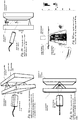
- Fig. 4a is a rough sketch of a cross-axial section of the linear ring-shaped ultrasound transducer (04) with some of its transducer elements (041),
- Fig. 4b is a rough illustration of a longitudinal section of the transducer housing sleeve (03) with its flexprint cable passages (0252) through the transverse wall (032) which carries the downward protruding central axle (034) for holding the transducer (04) and the front portion (06).
- Fig. 5a-d is a machine drawing of a preferred embodiment of the logging tool according to the invention, i.e. showing the mechanical structure of the tool to some detail.
- Fig. 5a is an elevation view of the logging tool according to the invention, with spanner slots in the main housing (01) near the upper end (011), and a removable protective end cap covering the connector plug (012) which preferably shall be connected to the dedicated memory tool (02).
- the transducer housing sleeve (03) In the lower end (013) of the main housing (01) is arranged the transducer housing sleeve (03) with the ultrasound transparent window (05) and the nose portion (06), all locked by the locking rings.
- the housing sleeve (03) and the nose portion (06) are provided with spanner slots for mounting and disconnection.
- a protective end cap, removable, is also shown.
- the protective cap is removed and provided with a centralizer before introduction to the well in order to hold the tool centrally in the production tubing when logging. This may restrict the temporal ranges required and facilitate caliper logging with the ultrasound tool, and also facilitate the ultrasound logging of tubing wall images and tubing wall thickness, and further facilitating the through wall Dopp
- Fig. 5b is a longitudinal section corresponding to the view of Fig. 5a .
- the ultrasound transducer array (04) with its ultrasound transducer elements connected through flexprint cables (0252) extending through passages (0341) through the transverse wall (032) up to a probe interface module (025) in the electronics structural frame (02).
- the probe interface module (025) connects further to a switch module (024), further connected to a transmitter/receiver module (023) which is digital to analog in the transmitter direction and analog to digital in the receiver direction.
- the t/r AD/DA converter module (023) is further connected to a processing module (022).
- a power module (021) serves the modules which require power, i.e. not the probe interface module.
- the electronic modules in their assembled state in the electronics structure frame (02) sled in place into the main housing (01) from the lower end (013), and locked in place by the transducer housing sleeve (03) screwed into lower end of the main housing (01).
- the tool is closed and pressure proof with the ultrasound transducer window (05) and the nose portion (06) are mounted on the central axle (034) and locked by the locking rings (061, 062).
- An advantage of the present assembly is the fact that the ultrasound transparent window (05) is easily replaceable by an onsite operator without disturbing the ultrasound transducer array (04).
- the connector plug (021) to the above subsequent tool preferably the dedicated memory tool (200).
- Fig. 5c shows an enlarged cross-section indicated by the ring in Fig. 5b , with details of threads, O-rings, and relative positions of inward and outward threads of the threaded components in the lower end (013).
- the upper locking ring (062) is flush with the outer diameter of the main housing (01) and the largest diameter of the ultrasound transparent window (05) and the lower locking ring (061).
- the central bolt (034) is massive in the illustrated embodiment.
- the ultrasound logging tool of the invention is arranged not to be the lowest of the logging tools in the toolstring.
- the nose portion portion is replaced by a connector sleeve for through electrical connection passing on from through the central bolt (034).
- Fig. 5d is a cross-section view through the line C-C of Fig. 5b , through the circular transverse wall (032) just above the transducer array (04).
- the section is shown looking in a downward direction from the lower end (013) of the main housing. From centre and out the section shows the central bolt (034) on the circular transverse wall (032), six holes (0331) with a spring array (033) holding pins (0332) extending from the inner, rear portion of the transducer array (04) as seen in Fig. 4b .
- This spring array yields upwardly in the axial direction when the transducer array (04) is moved by the compressed ultrasound transducer window (05) due to their common conic interface, when subject to increasing pressure in the well, preventing deformation or mechanical damage of the transducer array.
- Radially outside the spring array holes are the through holes (0341) through the circular transverse wall (032) for the flexprint cables (0252). Radially outside this the circular transverse wall continues into the cylindrical portion of the transducer housing (03), followed by a gasket groove, the upper portion of the ultrasound transducer window (05), and finally the lower portion of the upper locking ring (062).
- Fig. 6a is a vertical section through an ultrasound array only according to the invention in a tubing and casing in a well, with a first fluid (F1) flowing upwardly in the tubing and with a second fluid (F2) flowing in the annulus space between the well casing and the tubing (3).
- the transducer surface (042) is arranged with an angle (V042) with the tool axis which should be parallel with the tubing axis. This assures avoiding a directly reflected ultrasound signal which could otherwise saturate the reception when in receiving mode, but utilizes backscattered p-waves propagating through the fluid (F1).
- Fig. 6b is an overview of those different modes of ultrasound pulse-echo petroleum well tubing logging.
- the actual logging mode is selectable through the main controller board (0220) in the logging tool, please see Fig. 7a , controlled through telemetry from the surface read-out unit and the logging operator.
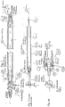
- Fig. 7a is a block diagram of the sensor, electronic, and communication main components of the logging tool of the invention.
- all control, communication, and data signals are digital, and all ultrasound signals are acoustic, analog, transducer selection, signal transmission and reception, amplification and transformation and processing must be conducted at an appropriate stage in order to obtain meaningful results.
- Fig. 7b is an illustration of ultrasound beams A and B formed by selecting consecutive elements 041 and beam forming by phase delays.
- the ultrasound logging tool according to the invention is assembled into a logging tool string.
- the 2 n elements (041) to either sides of the selected centre line are selected to be the two azimuthal parts of the array of 2x2 n elements (041) forming each beam (A) and (B), please see Fig. 7b .
- the central element when operating with radially directed beams (A) and (B), the central element is shifted one at a time, covering 180 degrees each for beam (A) and (B), thus together covering 360 degrees for a half, 180 degrees turn of the centre line.
- each of 2x2 n consecutive transducer elements (041) must be "receipt beamformed” to be focused at one single point at some stage before they are stacked and further processed.
- this "beam forming" (or wavefront selection) is conducted at the Rx beamformer module (0237), please see Fig. 7a .
- the central line between two central transducer elements (041) is shifted laterally (azimuthally) one element at a time (or several elements at a time, depending on desired azimuthal resolution), covering 180 degrees each for beam (A) and (B), thus together covering 360 degrees for a half turn of the centre line.
- both Tx and Rx are repeated for the same beam A and / or B for providing a velocity estimate over a given time range. It is possible to adjust the focus as an inhomogeneity source of the Doppler signal approaches.
- the above steps with transmission and reception relates to one sampling of one reflection point in one "depth" of investigation from the transducer.
- one pixel height image scan has been conducted azimuthally, i.e. around the periphery around the transducer ring. This may be a caliper measure scan, an image scan, or a Doppler scan.
- Such scanned rings may be assembled to a 2-D image of the surroundings for each focus depth, the dimension of the 2-D image determined by the logging depth registrations at the surface log or other depth indicator.
- Fig. 8a illustrates a vertical section through an experimental setup in a water tank, wherein a multi-transducer scanner head is submerged in the tank at a small distance from a steel plate and directed 17 degrees incidence angle on the plate, and wherein a slow water flow is set up behind the steel plate.
- the water and steel bodies may be compared from left to right with the tubing-internal fluid F1, here water, the tubing wall, the annulus fluid F2, here water, and the casing wall.
- Fig. 8b is a vertical view of the same.
- Fig. 8c shows, in a view corresponding to Fig. 8b , a colour Doppler image resulting from the setup in Figs. 8a and 8b , wherein bubbles have been introduced into the water flow.
- the lighter portions in the middle indicate upward flow up to 20 cm/s or more, while the darker portions to the sides indicate no flow or slightly downward flow.
- the image clearly indicates detectability of the bubbles in the water, and that their velocity upward or downward may be measured.
- Fig. 8d shows, in a similar top perspective compared to Fig. 8c and turned 90 degrees, a colour Doppler image of an upwelling water flow with bubbles introduced as illustrated in Figs. 8a, b, and c .
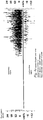
- Fig. 8e is an illustration of a spectral Doppler time series of the same experimental setup illustrated in Fig. 8a and 8b .
- Above the abscissa are approaching or upward flow values up to 24 cm/s, below the abscissa are negative values from -12 cm/s.
- the detected values for each instant range from about 2 cm/s to above 15 cm/s, and also some negative speed values. There is a wide variation of velocities for each instant of time.
- Fig. 9 is a vertical section through a tubing with a high data bit rate producing logging tool of the invention assembled into a logging tool string comprising other logging tools, not necessarily producing data at a high bit rate.
- the logging tool of the invention is combined with a dedicated memory tool section (200) arranged just above the ultrasound logging tool's (0) upper end, with the high data bit rate LVDS bus to the high-speed / high capacity memory tool's (200) memory section, which is also connected to the ordinary toolbus (10) of the toolstring.
- Figs. 10a and 10b shows in slightly more detail the features of Fig. 9 and roughly indicate the main components of Fig. 7a , such as a ring-shaped ultrasound transducer array here named (1s), a number of conductors to the probe interface module (025), switch module (024), Tx/Rx ADC module (023), Tx/Rx beamformer module (0235, 0237), beamformer / switch control board (0239) (which sends control signals to switch module (024), please see Fig. 7a ).
- a ring-shaped ultrasound transducer array here named (1s)
- (1s a number of conductors to the probe interface module
- switch module (024
- Tx/Rx ADC module (023
- Tx/Rx beamformer module (0235, 0237
- beamformer / switch control board (0239) (which sends control signals to switch module (024), please see Fig. 7a ).
- the invention is a a petroleum production well ultrasound imaging and annulus fluid velocity logging tool (0), for use in a production tubing (3) conducting a first tubing flow (30) of a first fluid (F1) and surrounded by a tubing annulus space (7) with annulus fluids (F2) in a petroleum production well (100).
- the logging sonde (0) according to the invention comprises
- Locking rings (061, 062) which are inward threaded and arranged from the nose portion (06) and the transducer housing (03) directions, respectively, secure the lower and upper axially directed sleeve portions of the US transparent window (05).
- the outer diameter of the locking rings (061) and (062) corresponds to the largest diameter of the main housing (01).
- the cross-section of the lower locking ring (062) is triangular and tapered off in order not to obstruct the outgoing and incoming ultrasound waves.
- the apparatus of the present invention may be used for two main purposes:
- the image scans and PW Doppler measurements are coupled to the wireline depth encoder measurements and may be assembled to corresponding images.
- An operator may first image a perforated production part of a well for forming an image of the location and geometry of the perforations made. Subsequently, the operator may shift the apparatus to run in PW Doppler mode for measuring the flow velocities in the area of the perforations detected and imaged.
- the combined image and measurements may provide valuable information on the production conditions in the perforated part of the well.
- the imaging is conducted in azimuthal scans with beams A and B of combined transmitter /receiver sequences as described above.
- Time windowing is selected in order to acquire a selected probing depth.
- the PW Doppler measurements of the fluid flow may be conducted in a selected part of the well, i.e. in the production pipe itself, or in an annulus, and depends on the time window selected by the operator.
- the transducer angle (V042) allows utilizing the transmission coefficient in the selected angle range which provides good s-wave transmission, which again allows detecting Doppler shifts due to particle or bubble velocities in the annulus, i.e. behind the tubing wall.
- the beam forming for conducting Doppler measurements is generally the same as the beam forming for backscatter imaging.
- the focus may be changed continuously with increasing two-way travel time during reception, so as for focusing on reflections with progressively increasing distance and two-way propagation time with increasing arrival time at the transducer, reflections which represent bubbles in increasing distance from the transducer.
- a PW Doppler acquisition may require a number of consecutive pulse emissions in the same direction in order to detect movement, e.g. a number of 16 pulse emissions.
- a PW Doppler measurement may be commanded by the main controller module to conduct so-called beam interleaving, i.e.
- the main controller module (0239) may also command beam interleaving while switching back and forth between PW backscatter imaging mode and PW Doppler mode in order to build a backscatter image of the interior of the tubing which is overlaid by annulus fluid velocity estimates.
- the transducer angle used in the present invention is not only for allowing signal transmission through the tubing wall to conduct measurements in the tubing annulus, but also for avoiding direct reflection from the pipe wall, as directly reflected signals contains far more energy than backscattering. Direct reflections would saturate the receiving transducer amplifiers if set to detect post-tubing signals.
- an auto-gain algorithm in the Rx analog front end pre-amplifiers (0234) may apply a pre- and post- tubing wall gain function wherein the distinction between pre- and post-tubing two-way travel time is based on automatic tubing wall detection algorithms. The two-way travel time may be deduced during imaging mode while conducting backscatter imaging of the tubing wall, or using pulse measurements during PW Doppler measurements.
- a PW Doppler processing is conducted in the Doppler processing unit 022D, please see Fig. 7a .
- the PW Doppler processing requires significantly more data to do an annulus velocity estimate than pulse-echo imaging of the tubing wall. Therefore it will only be possible to do Doppler processing in a limited number for beam directions at the time because of time of flight limitations. This is because each pulse has to travel all the way from transducer surface to the sample volume at the desired distance and back before a new beam can be sent. If it takes too long time between each time a beam is sent in a specific direction (e.g. while performing beam interleaving) aliasing will occur.
- the measured fluid velocities should be corrected for the vertical speed of the tool itself. Irregular movements of the tool may produce reflections which may be attenuated using a clutter filter, please see below.
- the clutter filter is a high pass filter such as illustrated in Fig. 12b .
- a number of different clutter filters with different cut-off frequencies may be implemented in the Doppler processing unit (022D) and be selectable from a filter bank depending on the detected instrument velocity relative to the tubing wall amongst other parameters.
- Color flow imaging is made using multi range PW Doppler; multiple sample volumes per region subject to measurements, per "region of interest" (ROI) in the annulus, for each beam.
- the signal power estimate can be made from a mean signal power estimator as above.
- the packet size the number of pulses to make one velocity vector needs to be kept low in order to achieve an acceptable temporal resolution.
- PW Doppler this is not as critical as only one beam direction is used and more samples can be used for filtering.
- a Doppler frequency spectrum is estimated and not only the mean frequency as is the case for Color flow.
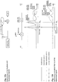
- the Doppler processing module (022D) may in an embodiment be implemented with a monitoring algorithm that continuously (which is particularly important if the tool's movement is uneven relative to the tubing wall) with adjustable averaging window and updating rate of mean frequency estimates conducts the following clutter filtering: Down-mixing the Doppler signal with the mean frequency ⁇ IN which can be estimated from the equation above, please see Fig.
- the center frequency of the tubing wall backscatter will thereby be brought close to 0 Hz, please see “downmixed spectrum” in Fig. 12b .
- the Doppler signal from the tubing wall is thereby maximum attenuated by a high-pass clutter filter, please see “filtered downmixed spectrum”.
- the Doppler signal can be mixed back to its original frequency, as shown in Fig. 12b , please see “up-mixed resulting spectrum”.
- the up-mixed signal is far less dominated by the low-frequency movement-induced clutter. Using this procedure will allow obtaining a Doppler signal of the weak reflections having passed the tubing wall, representing bubbles, particles or inhomogeneities moving in the tubing annulus.
- a significant advantage of the apparatus of the invention is that one may obtain focused Doppler measurements through the tubing wall of fluid movements.
- the Doppler annulus measurements may be clutter filtered for correcting for tool movements.
- One may switch between backscatter imaging mode and Doppler mode, which are both conducted and controlled by software in the tool itself, using control software from the surface.
- the apparatus is materially the same for the two modes. This implies that one may run several passes in imaging and Doppler mode without having to pull the tool from the well between the two modes. It will also allow combining the two modes in a common user interface at the surface.
- the tool of the invention may be used for Doppler measurement of flow of fluids through the tubing wall, and the selection of the conical angle to allow s-waves through the tubing wall will in addition reduce direct reflections from the inner face of the tubing, which would otherwise drown the Doppler signal.
- the Doppler processing and filtering contributes to enhance the weak annulus Doppler signals to allow annulus velocity measurements.
Landscapes
- Physics & Mathematics (AREA)
- Life Sciences & Earth Sciences (AREA)
- General Physics & Mathematics (AREA)
- Engineering & Computer Science (AREA)
- Geology (AREA)
- Mining & Mineral Resources (AREA)
- Acoustics & Sound (AREA)
- Fluid Mechanics (AREA)
- General Health & Medical Sciences (AREA)
- Immunology (AREA)
- Pathology (AREA)
- Health & Medical Sciences (AREA)
- Chemical & Material Sciences (AREA)
- Analytical Chemistry (AREA)
- Biochemistry (AREA)
- Environmental & Geological Engineering (AREA)
- Geochemistry & Mineralogy (AREA)
- General Life Sciences & Earth Sciences (AREA)
- Geophysics (AREA)
- Electromagnetism (AREA)
- Remote Sensing (AREA)
- Investigating Or Analyzing Materials By The Use Of Ultrasonic Waves (AREA)
- Measurement Of Velocity Or Position Using Acoustic Or Ultrasonic Waves (AREA)
Claims (14)
- Verfahren zur drahtgebundenen Ölquellen-Steigrohrmessung mit Impulswellen-Ultraschall, umfassend das Anordnen eines Bohrlochmesswerkzeugs (0) in dem Steigrohr, wobei das Bohrlochmesswerkzeug (0) über einen Werkzeugbus (10) und ein Bohrloch-Telemetriemodem über eine Drahtleitung mit einer Oberflächen-Ausleseeinheit kommuniziert, wobei das Bohrlochmesswerkzeug mit einer kegelstumpfförmigen ringförmigen linearen Ultraschall-Wandleranordnung (04) versehen ist, die eine Anzahl (m) von schmalen, radial gerichteten Ultraschall-Wandlerelementen (041) mit Wandleroberflächen (042), die eine konische Seitenfläche (043) bilden, umfasst, gekennzeichnet durch- Steuern des Bohrlochmesswerkzeugs, um selektiv in einem PW-Rückstreu-Bildgebungsverarbeitungsmodus und einem Doppler-Messverarbeitungsmodus zu arbeiten, für eine Reihe von Sendungen und Empfängen von gepulstem Ultraschall gegen einen fokussierten Punkt unter Verwendung der kegelstumpfförmigen ringförmigen linearen Ultraschall-Wandleranordnung (04), umfassend- Senden von fokussierten Ultraschallwellenimpulsen als zwei gegenläufige Ultraschallstrahlen (A) und
(B) in einer von der konischen Oberfläche orthogonalen Richtung zu einem umgebenden Bohrlochfluid in dem Steigrohr und- Empfangen, Wandeln von analog zu digital und Durchführen von Beamforming mit zurückkehrenden Ultraschallsignalen, die die gegenläufigen Strahlen (A) und (B) darstellen, und Bilden einer Signalhüllkurve der demodulierten digitalisierten Signalzeitreihe für jeden Strahl (A) und (B);- Quantisieren, in dem PW-Rückstreumodus, der umhüllten Ultraschalldaten, um Ultraschallbilddaten für einen fokussierten Punkt für jeden Strahl (A) und (B) zu bilden,- Verwenden, in dem Doppler-Modus, einer Reihe der demodulierten digitalisierten Zeitsignalreihen, die Doppler-Messdaten für den fokussierten Punkt für jeden Strahl (A) und (B) erzeugen,- Durchführen, während des Doppler-Messwertverarbeitungsmodus, von Doppler-Messungen, Berechnen einer mittleren, relativ niedrigen Geschwindigkeit der Doppler-Daten, die eine relativ niedrige Werkzeuggeschwindigkeit darstellen, und Verwenden der mittleren, relativ niedrigen Geschwindigkeit zur Durchführung einer Stördaten-Filterung zum Entfernen von Doppler-Daten, die die relativ niedrige Werkzeuggeschwindigkeit darstellen, Verarbeiten der gefilterten Doppler-Daten zum Erhalten von Doppler-Daten, die aufgrund einer Fluidströmung in einem Ringraum außerhalb des Steigrohrs entstehen, wobei in dem Prozess der Stördaten-Filterung die Doppler-Daten mit der mittleren, relativ niedrigen Geschwindigkeit einem Downsampling unterzogen werden, um ein Frequenzspektrum der einem Downsampling unterzogenen Daten, die Stördaten darstellen, auf eine Frequenz nahe Null zu bringen, und die Doppler-Daten hochpassgefiltert werden, um den Beitrag der Doppler-Daten, die eine relativ niedrige Geschwindigkeit darstellen, zu entfernen,- Senden aller oder eines Teils der gebildeten Ultraschallbilder und Doppler-Daten auf dem Werkzeugbus (10) über die Drahtleitung an die Oberflächen-Ausleseeinheit. - Verfahren nach Anspruch 1, zum Senden von Ultraschallwellen,
Erzeugen einer Anzahl (n) von digitalen Signalen, Durchführen von Beamforming mit dieser Anzahl (n) von digitalen Signalen, um fokussierte Ultraschallstrahlen (A, B) dazustellen,- Umwandeln der digitalen Signale in die Anzahl (n) von Spannungsansteuersignalen,- Verbinden der Anzahl (n) von Spannungssteuersignalkanälen mit zwei entgegengesetzt gerichteten, aufeinanderfolgenden Reihen, die jeweils das Doppelte der Anzahl (n) der Wandlerelemente (041) aufweisen,- Senden von fokussierten Ultraschallwellenimpulsen als die beiden gegenläufigen Ultraschallstrahlen (A) und (B) in einer von der konischen Oberfläche orthogonalen Richtung zu dem umgebenden Bohrlochfluid in dem Steigrohr,- Empfangen von zurückkehrenden Ultraschallsignalen und Umwandeln in analoge Spannungssignale an den beiden ausgewählten entgegengesetzt gerichteten aufeinanderfolgenden Reihen von Wandlerelementen, die die gegenläufigen Strahlen (A) und (B) darstellen,- Verstärken der empfangenen analogen Spannungssignale,- Umwandeln der empfangenen analogen Spannungssignale in empfangene digitale Signale und Durchführen von Beamforming mit den empfangenen digitalen Signalen und Kombinieren der empfangenen digitalen Signale zu einer empfangenen digitalisierten Ultraschall-Zeitsignalreihe für jeden Ultraschallstrahl (A) und (B),- Demodulieren der empfangenen digitalisierten Zeitsignalreihen für jeden Strahl (A} und (B),- Bilden einer Signalhüllkurve der demodulierten digitalisierten Zeitsignalreihe für jeden Strahl (A) und (B),- wobei die kegelstumpfförmige ringförmige lineare Ultraschallwandleranordnung (04) eine
Anzahl (n) schmaler, radial gerichteter Ultraschallwandlerelemente (041) umfasst, deren Wandlerflächen (042) einen Teil einer konischen Seitenfläche (043) der Ultraschallanordnung (04) mit einem Konuswinkel zwischen 12 und 28 Grad bilden, die die Ultraschallsignale senden. - Verfahren nach einem der Ansprüche 1 bis 2, wobei alle oder ein Teil der durch Ultraschall erzeugten Bilder oder Doppler-Daten über einen dedizierten Hochgeschwindigkeits-Speicherbus zum Zwischenspeichern an ein dediziertes Bohrloch-Speicherwerkzeug (200), das mit dem Bohrlochmesswerkzeug verbunden ist, gesendet werden, wobei das Speicherwerkzeug (200) ferner mit dem gewöhnlichen Werkzeugbus (10) verbunden ist.
- Verfahren nach einem der Ansprüche 1 bis 3, wobei die Doppler-Messungen das Berechnen der Fluidgeschwindigkeit, der Fluidströmungsrichtung, der Signalleistung oder der spektralen Information über die Strömungsgeschwindigkeit umfassen.
- Drahtgebundenes Ultraschall-Bohrlochesswerkzeug nach einem der Ansprüche 1 bis 4, wobei die Anzahl (n) der signalerzeugenden Kanäle n = 2, 4, 8, 16, 32 oder 64 Kanäle ist.
- Verfahren nach einem der Ansprüche 1 bis 5, wobei eine zeitgesteuerte Verstärkung der Anzahl (n) von Signalen in den Kanälen in dem analogen Empfänger-Eingangsverstärker (0234) für Zweiwege-Laufzeiten durchgeführt wird, die eine vorherige und nachherige Rückstreuung von einer Innenwand des Steigrohrs darstellen.
- Verfahren nach einem der Ansprüche 1 bis 6, wobei bei dem Prozess der Stördaten-Filterung die Doppler-Daten mit der mittleren, relativ niedrigen Geschwindigkeit einem Downsampling unterzogen werden, um ein Frequenzspektrum der dem Downsampling unterzogenen Daten, die Stördaten darstellen, auf eine Frequenz nahe Null zu bringen, und die Doppler-Daten hochpassgefiltert werden, um den Beitrag der Doppler-Daten, die eine relativ niedrige Geschwindigkeit darstellen, zu entfernen.
- Verfahren nach einem der Ansprüche 1 bis 7, wobei eine Doppler-Verarbeitung für Zeitbereiche, die Zweiwege-Laufzeiten für Sendungen von der Wandleroberfläche (042) durch das Fluid in dem Steigrohr unter dem gewünschten Winkel als Scherwellen durch die Steigrohrwand und durch das Ringraumfluid zu Inhomogenitäten in dem Ringraumfluid darstellen, durchgeführt wird, wodurch Doppler-Messdaten für das Ringraumfluid erhalten werden.
- Verfahren nach einem der Ansprüche 1 bis 8, umfassend das seitliche Verschieben der Strahlen (A) und (B), um azimutal von dem Bereich von Interesse Linienbildscans aufzubauen,- Durchführen der Strahlverschachtelung eines oder beider Strahlen (A) oder (B), um den Aufbau eines Rückstreubildes und eines Doppler-Bildes im selben Durchlauf zu ermöglichen,- Durchführen einer Strahlverschachtelung eines oder beider Strahlen (A) oder (B), um zu ermöglichen, dass eine ausreichende Bewegung einer Inhomogenität in dem Fluid in dem Steigrohr oder in dem Steigrohrringraum zwischen aufeinanderfolgenden Ultraschallimpulswellen, die von der angenommenen gleichen Inhomogenität zurückkehren, auftritt,- Senden, im Doppler-Modus, von berechneten Doppler-Messdaten an das Hauptsteuermodul (0220).
- Verfahren nach einem der Ansprüche 1 bis 9, wobei die Anzahl (m) der Elemente in dem ringförmigen Ultraschallwandler (04) zwischen 64 und 512, insbesondere in einer Ausführungsform, m = 288 beträgt.
- Verfahren nach einem der Ansprüche 1 bis 10, umfassend das Durchführen einer Pulswellen-Rückstreu-Bildverarbeitung für Zeitbereiche, die Zweiwege-Laufzeiten für Sendungen von der Wandleroberfläche (042) durch das Fluid in dem Steigrohr unter dem gewünschten Winkel als Scherwellen durch die Steigrohrwand und zu Objekten oder Merkmalen auf der Außenfläche der Steigrohrwand oder durch das Ringraumfluid zu Objekten außerhalb der Steigrohrwand darstellen, wodurch Bildpunktmessungen der Objekte erhalten werden.
- Verfahren nach einem der Ansprüche 1 bis 11, umfassend, nach dem Durchführen von Beamforming mit den empfangenen Signalen, das Einstellen des Fokus auf zunehmende Radien bei zunehmender Zweiwege-Laufzeit und,- um Sättigung zu vermeiden, einen Auto-Verstärkungs-Algorithmus in dem empfangenden analogen Eingangs-Vorverstärkern (0234), der eine Verstärkungsfunktion vor und nach dem Steigrohr anwendet,- wobei die Unterscheidung zwischen der Zweiwege-Laufzeit vor und nach dem Steigrohr auf einem Steigrohrwand-Erfassungsalgorithmus basiert, wobei die Zweiwege-Laufzeit während des Bildgebungsmodus abgeleitet wird, während eine Rückstreuabbildung der Steigrohrwand durchgeführt wird, oder wobei Impulsmessungen während PW-Doppler-Messungen verwendet werden.
- Werkzeug für drahtgebundene Ölquellen-Steigrohrmessung mit Impulswellen-Ultraschall, umfassend- ein zylindrisches, druckfestes Hauptgehäuse (01) mit einem Verbinder an seinem oberen Ende (011) zum Kommunizieren über einen Werkzeugbus (10) und ein Bohrloch-Telemetriemodem über eine Drahtleitung mit einer Oberflächen-Ausleseeinheit, gekennzeichnet durch- das druckfestes Hauptgehäuse (01), das versehen ist mit- einem Ultraschallwandler-Gehäusehülsenteil (03) mit einer kegelstumpfförmigen, ringförmigen, linearen Ultraschallwandleranordnung (04), die eine Anzahl (m) von schmalen, radial gerichteten Ultraschall-Wandlerelementen (041) umfasst, deren Wandlerflächen (042) eine konische Seitenfläche (043) bilden, und die Wandlerelemente (042) zum Senden von Ultraschallenergie an ein umgebendes Bohrlochfluid in dem Steigrohr dienen, wobei die konische Fläche (043) einen konischen Winkel aufweist,- ein Hauptsteuermodul (0220), das dazu angeordnet ist, um zwischen einem PW-Echorückstreu-Bildgebungsverarbeitungsmodus in einem Signalverarbeitungsmodul (022) und einem Doppler-Messverarbeitungsmodus für eine Reihe von gepulsten Ultraschallsendungen und -empfängen gegen einen fokussierten Punkt unter Verwendung der kegelstumpfförmigen ringförmigen linearen Ultraschallwandleranordnung (04) selektiv umzuschalten- um fokussierte Ultraschallwellenimpulsen als zwei gegenläufige Ultraschallstrahlen (A) und (B) in einer zu der konischen Oberfläche senkrechten Richtung zu einem umgebenden Bohrlochfluid in dem Steigrohr zu senden, und- um zurückkehrende Ultraschallsignale, die die gegenläufigen Strahlen (A) und (B) darstellen, zu empfangen und Analog-Digital-Wandlung und Beamforming durchzuführen, und das dazu angeordnet ist, eine Signalhüllkurve der demodulierten digitalisierten Signalzeitreihe für jeden Strahl (A) und (B) bilden;- wobei die Signalverarbeitungseinheit (022) für das In-Phasen- und Quadratur-Demodulationsmodul (0221) zum Demodulieren der Zeitsignalreihe angeordnet ist,- wobei das Hauptsteuermodul (0220) zum Senden komprimierter Bild- oder Doppler-Daten auf dem Werkzeugbus-Steuermodul (02201)
an den Werkzeugbus (10) angeordnet ist, um mit der Oberflächen-Ausleseeinheit zu kommunizieren,- ein Doppler-Verarbeitungsmodul (022D), das dazu angeordnet ist, während des Doppler-Messverarbeitungsmodus eine mittlere, relativ niedrige Geschwindigkeit der Doppler-Daten, die eine relativ niedrige Werkzeuggeschwindigkeit darstellen, zu berechnen und die mittlere, relativ niedrige Geschwindigkeit zu verwenden, um eine Stördaten-Filterung durchzuführen und somit Doppler-Daten zu entfernen, die die relativ niedrige Werkzeuggeschwindigkeit darstellen, um die gefilterten Doppler-Daten zu verarbeiten, um Doppler-Daten zu erhalten, die aufgrund von Fluidströmung in einem Ringraum außerhalb des Steigrohrs entstehen, wobei bei dem Prozess der Stördaten-Filterung das Doppler-Verarbeitungsmodul ferner dazu angeordnet ist, die Dopplerdaten mit der mittleren, relativ niedrigen Geschwindigkeit einem Downsampling zu unterziehen, um ein Frequenzspektrum der einem Downsampling unterzogenen Daten, die Stördaten darstellen, auf eine Frequenz nahe Null zu bringen, und die Doppler-Daten einer Hochpassfilterung zu unterziehen, um den Beitrag der Doppler-Daten, die eine relativ niedrige Geschwindigkeit darstellen, zu entfernen. - Vorrichtung nach Anspruch 13, umfassend- ein Hauptsteuermodul (0220) mit einem Beamformer-/Schaltsteuer-Modul (0239), das zum Steuern eines Sender-Beamformer-Moduls (0235) und eines Wandler-Schaltmoduls (024) zum Steuern und Umschalten zwischen Senden und Empfangen von Ultraschallsignalen angeordnet ist,- zum Senden, Steuern einer Anzahl (n) von Signalerzeugungskanälen in dem Sender-Beamformer-Modul (0235) angeordnet ist, um die Anzahl (n) von digitalen Signalen zu erzeugen, wobei das Sender-Beamformer-Modul (0235) die Anzahl (n) von digitalen Signalen einem Beamforming unterzieht, um den gepulsten, fokussierten Ultraschallstrahl (A, B) darzustellen,- zum Umwandeln der digitalen Signale in die gleiche Anzahl (n) von analogen Sendertreiber-Verstärkerkanälen in einem Sendertreiber-Modul (0233) angeordnet ist, um die Anzahl (n) von Spannungsansteuersignalen zu bilden,- zum Senden der Anzahl (n) von Spannungsansteuersignalen über Sender/Empfänger-Schalter (0232) an das Wandler-Schaltmodul (024) angeordnet ist, wobei das Wandler-Schaltmodul (024) die Anzahl (n) von Spannungsansteuersignalkanälen mit zwei entgegengesetzten, aufeinanderfolgenden Reihen verbindet, die jeweils das Doppelte der Anzahl (n) der Wandlerelemente (041) aufweisen,- wobei das Wandler-Schaltmodul (024) zum Umschalten und zum Verbinden der zwei ausgewählten entgegengesetzten aufeinanderfolgenden Reihen von jeweils der doppelten Anzahl (n) von Wandlerelementen (041) intern und paarweise symmetrisch in jeder aufeinanderfolgenden Reihe (A, B) mit der Anzahl (n) von Kanälen in zwei getrennten analogen Empfänger-Eingangsverstärkerkanälen (0234), die die gegenläufigen Strahlen (A) und (B) darstellen, zum Verstärken der empfangenen analogen Spannungssignale angeordnet ist,- zum Senden der Signale der verstärkten Kanäle an parallele Empfänger-Beamformer-Module (0237), von denen jedes mit der Anzahl (n) von Kanälen die Anzahl (n) von Signalen digital umwandelt und zu einer Ultraschall-Zeitsignalreihe für jeden Ultraschallstrahl (A) und (B) kombiniert, angeordnet ist,- eine Signalverarbeitungseinheit (022), die für jeden Strahl (A) und (B), für ein In-Phasen- und Quadratur-Demodulationsmodul (0221) zur Demodulation der Zeitsignalreihe angeordnet ist,- wobei das Hauptsteuermodul (0220) zum Umschalten zwischen dem PW-Echorückstreuungs-Bildgebungsverarbeitungsmodus in dem Signalverarbeitungsmodul (022) und einem
Doppler-Messverarbeitungsmodus in dem Doppler-Verarbeitungsmodul (022D) angeordnet ist,- wobei das Verarbeitungsmodul (022) ein Signalhüllkurvenbildungsmodul (0225), das zur Bildung einer Signalhüllkurve der IQ demodulierten Daten angeordnet ist, und einen Quantisierer (0227) zum Senden von quantisierten Ultraschalldaten an ein Bildkomprimierungsmodul in dem Hauptsteuermodul (0220) umfasst,- einen Doppler-Puffer zum Zwischenspeichern demodulierter digitaler Signalreihen in dem Doppler-Verarbeitungsmodul (022D), und angeordnet zum Durchführen einer Doppler-Verarbeitung in dem PW-Doppler-Verarbeitungsmodul (022D).
Applications Claiming Priority (1)
| Application Number | Priority Date | Filing Date | Title |
|---|---|---|---|
| PCT/NO2013/000056 WO2015088351A1 (en) | 2013-12-09 | 2013-12-09 | Pulse-wave ultrasound production well logging method and tool |
Publications (2)
| Publication Number | Publication Date |
|---|---|
| EP3080558A1 EP3080558A1 (de) | 2016-10-19 |
| EP3080558B1 true EP3080558B1 (de) | 2020-04-08 |
Family
ID=49918793
Family Applications (1)
| Application Number | Title | Priority Date | Filing Date |
|---|---|---|---|
| EP13818026.0A Active EP3080558B1 (de) | 2013-12-09 | 2013-12-09 | Verfahren und werkzeug zur ölquellenmessung mit impulswellen-ultraschall |
Country Status (3)
| Country | Link |
|---|---|
| US (1) | US20160290847A1 (de) |
| EP (1) | EP3080558B1 (de) |
| WO (1) | WO2015088351A1 (de) |
Cited By (1)
| Publication number | Priority date | Publication date | Assignee | Title |
|---|---|---|---|---|
| GB2555978B (en) * | 2015-06-17 | 2022-08-17 | Darkvision Tech Inc | Ultrasonic imaging device and method for wells |
Families Citing this family (30)
| Publication number | Priority date | Publication date | Assignee | Title |
|---|---|---|---|---|
| EP2446115A4 (de) * | 2009-06-24 | 2013-09-11 | Tecwel As | Umwandleranordnung |
| WO2016145524A1 (en) * | 2015-03-16 | 2016-09-22 | Darkvision Technologies Inc. | Device and method to image flow in oil and gas wells using phased array doppler ultrasound |
| US20170139077A1 (en) * | 2015-03-17 | 2017-05-18 | Halliburton Energy Services, Inc | Optimization of Downhole Logging Tool Data Resolution |
| EP3085882A1 (de) * | 2015-04-22 | 2016-10-26 | Welltec A/S | Bohrlochwerkzeugstrang zum zurückzementieren und aufgeben durch schneiden |
| US11221314B2 (en) * | 2015-09-20 | 2022-01-11 | Baker Hughes Oilfield Operations Llc | Combined pulse echo inspection of pipeline systems |
| CA2999363C (en) * | 2015-10-09 | 2023-02-21 | Osman S. MALIK | Devices and methods for imaging wells using phased array ultrasound |
| NO342779B1 (en) * | 2016-02-03 | 2018-08-06 | Ind Controls As | Apparatus and method for transferring information acoustically |
| AU2016396055B2 (en) * | 2016-03-03 | 2022-12-08 | Halliburton Energy Services, Inc. | Casing thickness estimation by frequency correlation |
| GB2558872A (en) | 2016-11-11 | 2018-07-25 | Schlumberger Technology Bv | Downhole tool for measuring fluid flow |
| GB2579743B (en) * | 2017-08-11 | 2022-03-02 | Ge Energy Oilfield Tech Inc | Multi-barrier wellbore integrity inspection system with eccentricity correction |
| GB2572834B8 (en) | 2018-08-16 | 2021-08-11 | Darkvision Tech Inc | Downhole imaging device and method of using same |
| GB2578123B8 (en) * | 2018-10-16 | 2021-08-11 | Darkvision Tech Inc | Overlapped scheduling and sorting for acoustic transducer pulses |
| US11372092B2 (en) * | 2019-01-04 | 2022-06-28 | Shenzhen Mindray Bio-Medical Electronics Co., Ltd. | Hybrid ultrasound transmitter |
| WO2020172468A1 (en) | 2019-02-21 | 2020-08-27 | Widril As | Method and apparatus for wireless communication in wells using fluid flow perturbations |
| CN110173258B (zh) * | 2019-06-20 | 2025-01-28 | 太平洋远景石油技术(北京)有限公司 | 一种超声井周成像测井仪 |
| GB2585366B (en) * | 2019-06-24 | 2021-08-25 | Darkvision Tech | Compression of Ultrasound Data in Fluid Conduits |
| GB2588194B (en) * | 2019-10-14 | 2021-12-08 | Yta B V | Information transfer system |
| GB2590065B (en) | 2019-11-08 | 2021-12-15 | Darkvision Tech Ltd | Using an acoustic device to identify external apparatus mounted to a tubular |
| CN111608644B (zh) * | 2020-05-06 | 2021-09-03 | 中国科学院武汉岩土力学研究所 | 一种阵列式声波扫描的高精度钻孔成像方法及装置 |
| US11428093B2 (en) * | 2020-09-29 | 2022-08-30 | Saudi Arabian Oil Company | Downhole investigation tool |
| US20220283330A1 (en) * | 2021-03-03 | 2022-09-08 | Halliburton Energy Services, Inc. | Gauge Length Correction For Seismic Attenuation From Distributed Acoustic System Fiber Optic Data |
| US11774630B2 (en) * | 2021-03-12 | 2023-10-03 | Baker Hughes Oilfield Operations Llc | Systems and methods for determining clean inelastic and capture spectra |
| CN113431551B (zh) * | 2021-05-27 | 2025-03-11 | 西安洛科电子科技股份有限公司 | 应用于油田分注井的非接触式流量测量装置及方法 |
| JP7762015B2 (ja) | 2021-08-31 | 2025-10-29 | 株式会社キーエンス | 超音波流量センサ |
| DE102021133933A1 (de) | 2021-12-20 | 2023-06-22 | Endress+Hauser Flowtec Ag | Signal-Übertragungssystem |
| US12291961B2 (en) * | 2022-04-20 | 2025-05-06 | Halliburton Energy Services, Inc. | In-situ bottomhole assembly analysis systems and methods to perform an in-situ analysis of a downhole communication system |
| CN120391045A (zh) | 2022-12-30 | 2025-07-29 | 恩德斯豪斯流量技术股份有限公司 | 发射/接收电路以及由其形成的信号传输系统 |
| DE102023105489A1 (de) | 2022-12-30 | 2024-07-11 | Endress + Hauser Flowtec Ag | Sende-/Empfangsschaltung sowie damit gebildetes Signal-Übertragungssystem |
| CN116203141B (zh) * | 2023-02-01 | 2026-01-02 | 中国国家铁路集团有限公司 | 钢轨探伤增益控制方法及装置 |
| CN119102608A (zh) * | 2023-06-07 | 2024-12-10 | 中国石油天然气集团有限公司 | 井筒的气侵监测装置及方法 |
Family Cites Families (2)
| Publication number | Priority date | Publication date | Assignee | Title |
|---|---|---|---|---|
| US3409869A (en) * | 1965-07-21 | 1968-11-05 | Navy Usa | Deep submergence acoustic transducer array construction |
| EP2446115A4 (de) * | 2009-06-24 | 2013-09-11 | Tecwel As | Umwandleranordnung |
-
2013
- 2013-12-09 EP EP13818026.0A patent/EP3080558B1/de active Active
- 2013-12-09 WO PCT/NO2013/000056 patent/WO2015088351A1/en not_active Ceased
- 2013-12-09 US US15/103,163 patent/US20160290847A1/en not_active Abandoned
Non-Patent Citations (1)
| Title |
|---|
| None * |
Cited By (1)
| Publication number | Priority date | Publication date | Assignee | Title |
|---|---|---|---|---|
| GB2555978B (en) * | 2015-06-17 | 2022-08-17 | Darkvision Tech Inc | Ultrasonic imaging device and method for wells |
Also Published As
| Publication number | Publication date |
|---|---|
| US20160290847A1 (en) | 2016-10-06 |
| WO2015088351A1 (en) | 2015-06-18 |
| EP3080558A1 (de) | 2016-10-19 |
Similar Documents
| Publication | Publication Date | Title |
|---|---|---|
| EP3080558B1 (de) | Verfahren und werkzeug zur ölquellenmessung mit impulswellen-ultraschall | |
| US10890563B2 (en) | Downhole tool with an ultrasonic probe for measuring fluid flow properties | |
| CN113534260B (zh) | 一种宽频带近海底深海地质结构声学探测系统与方法 | |
| EP2297595B1 (de) | Vorrichtung und verfahren zur erzeugung eines schallenergiestrahls aus einem bohrloch und anwendungen dafür | |
| USRE43090E1 (en) | Acoustic Doppler channel flow measurement system | |
| Flewellen et al. | TOBI, a vehicle for deep ocean survey | |
| US20160170063A1 (en) | Multi-beam phased array acoustic transducer operation for downhole applications | |
| CN111308474A (zh) | 拖曳式深海海底浅层结构声学探测系统及方法 | |
| NO162254B (no) | Fremgangsmaate og apparat for aa detektere frakturer. | |
| US4924449A (en) | Acoustic sub-surface interrogator | |
| GB2578697A (en) | Formation acoustic property measurement with beam-angled transducer array | |
| Holland et al. | Seabed observations at the New England Mud Patch: Reflection and scattering measurements and direct geoacoustic information | |
| US10718865B2 (en) | Method of compressing beamformed sonar data | |
| CN113777653A (zh) | 一种合成孔径式浅层地震剖面勘探方法和系统 | |
| Hou et al. | Tests of new in-situ seabed acoustic measurement system in Qingdao | |
| Morys et al. | Advances in borehole imaging in unconventional reservoirs | |
| CN100456045C (zh) | 一种浅地层剖面仪测量海底沉积物特性的方法及系统 | |
| Theuillon et al. | High-resolution geoacoustic characterization of the seafloor using a subbottom profiler in the Gulf of Lion | |
| Mayer et al. | In-situ determination of the variability of seafloor acoustic properties: An example from the ONR GEOCLUTTER area | |
| Zverev et al. | Experimental studies of sound diffraction by moving inhomogeneities under shallow-water conditions | |
| NO20131637A1 (no) | Forbedret nedihulls målemetode | |
| CN100456046C (zh) | 一种对海底多金属结核矿进行测量的声学方法及系统 | |
| CN101937103B (zh) | 用于辅助拖缆定位的包括定义及产生声学循环步骤的方法 | |
| GB1599067A (en) | Ultrasonic testing | |
| Belkacem et al. | Planar SAS for sea bottom and subbottom imaging: Concept validation in tank |
Legal Events
| Date | Code | Title | Description |
|---|---|---|---|
| PUAI | Public reference made under article 153(3) epc to a published international application that has entered the european phase |
Free format text: ORIGINAL CODE: 0009012 |
|
| 17P | Request for examination filed |
Effective date: 20160711 |
|
| AK | Designated contracting states |
Kind code of ref document: A1 Designated state(s): AL AT BE BG CH CY CZ DE DK EE ES FI FR GB GR HR HU IE IS IT LI LT LU LV MC MK MT NL NO PL PT RO RS SE SI SK SM TR |
|
| AX | Request for extension of the european patent |
Extension state: BA ME |
|
| DAX | Request for extension of the european patent (deleted) | ||
| GRAP | Despatch of communication of intention to grant a patent |
Free format text: ORIGINAL CODE: EPIDOSNIGR1 |
|
| STAA | Information on the status of an ep patent application or granted ep patent |
Free format text: STATUS: GRANT OF PATENT IS INTENDED |
|
| INTG | Intention to grant announced |
Effective date: 20191014 |
|
| GRAJ | Information related to disapproval of communication of intention to grant by the applicant or resumption of examination proceedings by the epo deleted |
Free format text: ORIGINAL CODE: EPIDOSDIGR1 |
|
| STAA | Information on the status of an ep patent application or granted ep patent |
Free format text: STATUS: REQUEST FOR EXAMINATION WAS MADE |
|
| GRAP | Despatch of communication of intention to grant a patent |
Free format text: ORIGINAL CODE: EPIDOSNIGR1 |
|
| STAA | Information on the status of an ep patent application or granted ep patent |
Free format text: STATUS: GRANT OF PATENT IS INTENDED |
|
| GRAS | Grant fee paid |
Free format text: ORIGINAL CODE: EPIDOSNIGR3 |
|
| GRAA | (expected) grant |
Free format text: ORIGINAL CODE: 0009210 |
|
| STAA | Information on the status of an ep patent application or granted ep patent |
Free format text: STATUS: THE PATENT HAS BEEN GRANTED |
|
| INTG | Intention to grant announced |
Effective date: 20200221 |
|
| AK | Designated contracting states |
Kind code of ref document: B1 Designated state(s): AL AT BE BG CH CY CZ DE DK EE ES FI FR GB GR HR HU IE IS IT LI LT LU LV MC MK MT NL NO PL PT RO RS SE SI SK SM TR |
|
| REG | Reference to a national code |
Ref country code: AT Ref legal event code: REF Ref document number: 1255007 Country of ref document: AT Kind code of ref document: T Effective date: 20200415 Ref country code: CH Ref legal event code: EP |
|
| REG | Reference to a national code |
Ref country code: DE Ref legal event code: R096 Ref document number: 602013067757 Country of ref document: DE |
|
| REG | Reference to a national code |
Ref country code: IE Ref legal event code: FG4D |
|
| REG | Reference to a national code |
Ref country code: NO Ref legal event code: T2 Effective date: 20200408 |
|
| REG | Reference to a national code |
Ref country code: NL Ref legal event code: MP Effective date: 20200408 |
|
| REG | Reference to a national code |
Ref country code: LT Ref legal event code: MG4D |
|
| PG25 | Lapsed in a contracting state [announced via postgrant information from national office to epo] |
Ref country code: SE Free format text: LAPSE BECAUSE OF FAILURE TO SUBMIT A TRANSLATION OF THE DESCRIPTION OR TO PAY THE FEE WITHIN THE PRESCRIBED TIME-LIMIT Effective date: 20200408 Ref country code: GR Free format text: LAPSE BECAUSE OF FAILURE TO SUBMIT A TRANSLATION OF THE DESCRIPTION OR TO PAY THE FEE WITHIN THE PRESCRIBED TIME-LIMIT Effective date: 20200709 Ref country code: FI Free format text: LAPSE BECAUSE OF FAILURE TO SUBMIT A TRANSLATION OF THE DESCRIPTION OR TO PAY THE FEE WITHIN THE PRESCRIBED TIME-LIMIT Effective date: 20200408 Ref country code: LT Free format text: LAPSE BECAUSE OF FAILURE TO SUBMIT A TRANSLATION OF THE DESCRIPTION OR TO PAY THE FEE WITHIN THE PRESCRIBED TIME-LIMIT Effective date: 20200408 Ref country code: NL Free format text: LAPSE BECAUSE OF FAILURE TO SUBMIT A TRANSLATION OF THE DESCRIPTION OR TO PAY THE FEE WITHIN THE PRESCRIBED TIME-LIMIT Effective date: 20200408 Ref country code: PT Free format text: LAPSE BECAUSE OF FAILURE TO SUBMIT A TRANSLATION OF THE DESCRIPTION OR TO PAY THE FEE WITHIN THE PRESCRIBED TIME-LIMIT Effective date: 20200817 Ref country code: IS Free format text: LAPSE BECAUSE OF FAILURE TO SUBMIT A TRANSLATION OF THE DESCRIPTION OR TO PAY THE FEE WITHIN THE PRESCRIBED TIME-LIMIT Effective date: 20200808 |
|
| REG | Reference to a national code |
Ref country code: AT Ref legal event code: MK05 Ref document number: 1255007 Country of ref document: AT Kind code of ref document: T Effective date: 20200408 |
|
| PG25 | Lapsed in a contracting state [announced via postgrant information from national office to epo] |
Ref country code: HR Free format text: LAPSE BECAUSE OF FAILURE TO SUBMIT A TRANSLATION OF THE DESCRIPTION OR TO PAY THE FEE WITHIN THE PRESCRIBED TIME-LIMIT Effective date: 20200408 Ref country code: RS Free format text: LAPSE BECAUSE OF FAILURE TO SUBMIT A TRANSLATION OF THE DESCRIPTION OR TO PAY THE FEE WITHIN THE PRESCRIBED TIME-LIMIT Effective date: 20200408 Ref country code: LV Free format text: LAPSE BECAUSE OF FAILURE TO SUBMIT A TRANSLATION OF THE DESCRIPTION OR TO PAY THE FEE WITHIN THE PRESCRIBED TIME-LIMIT Effective date: 20200408 Ref country code: BG Free format text: LAPSE BECAUSE OF FAILURE TO SUBMIT A TRANSLATION OF THE DESCRIPTION OR TO PAY THE FEE WITHIN THE PRESCRIBED TIME-LIMIT Effective date: 20200708 |
|
| PG25 | Lapsed in a contracting state [announced via postgrant information from national office to epo] |
Ref country code: AL Free format text: LAPSE BECAUSE OF FAILURE TO SUBMIT A TRANSLATION OF THE DESCRIPTION OR TO PAY THE FEE WITHIN THE PRESCRIBED TIME-LIMIT Effective date: 20200408 |
|
| REG | Reference to a national code |
Ref country code: DE Ref legal event code: R097 Ref document number: 602013067757 Country of ref document: DE |
|
| PG25 | Lapsed in a contracting state [announced via postgrant information from national office to epo] |
Ref country code: IT Free format text: LAPSE BECAUSE OF FAILURE TO SUBMIT A TRANSLATION OF THE DESCRIPTION OR TO PAY THE FEE WITHIN THE PRESCRIBED TIME-LIMIT Effective date: 20200408 Ref country code: CZ Free format text: LAPSE BECAUSE OF FAILURE TO SUBMIT A TRANSLATION OF THE DESCRIPTION OR TO PAY THE FEE WITHIN THE PRESCRIBED TIME-LIMIT Effective date: 20200408 Ref country code: RO Free format text: LAPSE BECAUSE OF FAILURE TO SUBMIT A TRANSLATION OF THE DESCRIPTION OR TO PAY THE FEE WITHIN THE PRESCRIBED TIME-LIMIT Effective date: 20200408 Ref country code: ES Free format text: LAPSE BECAUSE OF FAILURE TO SUBMIT A TRANSLATION OF THE DESCRIPTION OR TO PAY THE FEE WITHIN THE PRESCRIBED TIME-LIMIT Effective date: 20200408 Ref country code: SM Free format text: LAPSE BECAUSE OF FAILURE TO SUBMIT A TRANSLATION OF THE DESCRIPTION OR TO PAY THE FEE WITHIN THE PRESCRIBED TIME-LIMIT Effective date: 20200408 Ref country code: EE Free format text: LAPSE BECAUSE OF FAILURE TO SUBMIT A TRANSLATION OF THE DESCRIPTION OR TO PAY THE FEE WITHIN THE PRESCRIBED TIME-LIMIT Effective date: 20200408 Ref country code: AT Free format text: LAPSE BECAUSE OF FAILURE TO SUBMIT A TRANSLATION OF THE DESCRIPTION OR TO PAY THE FEE WITHIN THE PRESCRIBED TIME-LIMIT Effective date: 20200408 Ref country code: DK Free format text: LAPSE BECAUSE OF FAILURE TO SUBMIT A TRANSLATION OF THE DESCRIPTION OR TO PAY THE FEE WITHIN THE PRESCRIBED TIME-LIMIT Effective date: 20200408 |
|
| PLBE | No opposition filed within time limit |
Free format text: ORIGINAL CODE: 0009261 |
|
| STAA | Information on the status of an ep patent application or granted ep patent |
Free format text: STATUS: NO OPPOSITION FILED WITHIN TIME LIMIT |
|
| PG25 | Lapsed in a contracting state [announced via postgrant information from national office to epo] |
Ref country code: PL Free format text: LAPSE BECAUSE OF FAILURE TO SUBMIT A TRANSLATION OF THE DESCRIPTION OR TO PAY THE FEE WITHIN THE PRESCRIBED TIME-LIMIT Effective date: 20200408 Ref country code: SK Free format text: LAPSE BECAUSE OF FAILURE TO SUBMIT A TRANSLATION OF THE DESCRIPTION OR TO PAY THE FEE WITHIN THE PRESCRIBED TIME-LIMIT Effective date: 20200408 |
|
| 26N | No opposition filed |
Effective date: 20210112 |
|
| PG25 | Lapsed in a contracting state [announced via postgrant information from national office to epo] |
Ref country code: SI Free format text: LAPSE BECAUSE OF FAILURE TO SUBMIT A TRANSLATION OF THE DESCRIPTION OR TO PAY THE FEE WITHIN THE PRESCRIBED TIME-LIMIT Effective date: 20200408 |
|
| REG | Reference to a national code |
Ref country code: CH Ref legal event code: PL |
|
| PG25 | Lapsed in a contracting state [announced via postgrant information from national office to epo] |
Ref country code: MC Free format text: LAPSE BECAUSE OF FAILURE TO SUBMIT A TRANSLATION OF THE DESCRIPTION OR TO PAY THE FEE WITHIN THE PRESCRIBED TIME-LIMIT Effective date: 20200408 |
|
| REG | Reference to a national code |
Ref country code: BE Ref legal event code: MM Effective date: 20201231 |
|
| PG25 | Lapsed in a contracting state [announced via postgrant information from national office to epo] |
Ref country code: IE Free format text: LAPSE BECAUSE OF NON-PAYMENT OF DUE FEES Effective date: 20201209 |
|
| PG25 | Lapsed in a contracting state [announced via postgrant information from national office to epo] |
Ref country code: LI Free format text: LAPSE BECAUSE OF NON-PAYMENT OF DUE FEES Effective date: 20201231 Ref country code: CH Free format text: LAPSE BECAUSE OF NON-PAYMENT OF DUE FEES Effective date: 20201231 |
|
| PG25 | Lapsed in a contracting state [announced via postgrant information from national office to epo] |
Ref country code: TR Free format text: LAPSE BECAUSE OF FAILURE TO SUBMIT A TRANSLATION OF THE DESCRIPTION OR TO PAY THE FEE WITHIN THE PRESCRIBED TIME-LIMIT Effective date: 20200408 Ref country code: MT Free format text: LAPSE BECAUSE OF FAILURE TO SUBMIT A TRANSLATION OF THE DESCRIPTION OR TO PAY THE FEE WITHIN THE PRESCRIBED TIME-LIMIT Effective date: 20200408 Ref country code: CY Free format text: LAPSE BECAUSE OF FAILURE TO SUBMIT A TRANSLATION OF THE DESCRIPTION OR TO PAY THE FEE WITHIN THE PRESCRIBED TIME-LIMIT Effective date: 20200408 |
|
| PG25 | Lapsed in a contracting state [announced via postgrant information from national office to epo] |
Ref country code: MK Free format text: LAPSE BECAUSE OF FAILURE TO SUBMIT A TRANSLATION OF THE DESCRIPTION OR TO PAY THE FEE WITHIN THE PRESCRIBED TIME-LIMIT Effective date: 20200408 |
|
| PG25 | Lapsed in a contracting state [announced via postgrant information from national office to epo] |
Ref country code: BE Free format text: LAPSE BECAUSE OF NON-PAYMENT OF DUE FEES Effective date: 20201231 |
|
| REG | Reference to a national code |
Ref country code: NO Ref legal event code: CHAD Owner name: ARCHER AS, NO |
|
| REG | Reference to a national code |
Ref country code: NO Ref legal event code: CREP Representative=s name: BRYN AARFLOT AS, STORTINGSGATA 8, 0161 OSLO, NORGE |
|
| P01 | Opt-out of the competence of the unified patent court (upc) registered |
Effective date: 20230528 |
|
| PGFP | Annual fee paid to national office [announced via postgrant information from national office to epo] |
Ref country code: GB Payment date: 20251219 Year of fee payment: 13 |
|
| PGFP | Annual fee paid to national office [announced via postgrant information from national office to epo] |
Ref country code: NO Payment date: 20251219 Year of fee payment: 13 |
|
| PGFP | Annual fee paid to national office [announced via postgrant information from national office to epo] |
Ref country code: LU Payment date: 20251215 Year of fee payment: 13 Ref country code: FR Payment date: 20251211 Year of fee payment: 13 |
|
| PGFP | Annual fee paid to national office [announced via postgrant information from national office to epo] |
Ref country code: DE Payment date: 20251222 Year of fee payment: 13 |