EP3081002B1 - Lautsprechergehäuse mit angeformten elektrischen leitern - Google Patents
Lautsprechergehäuse mit angeformten elektrischen leitern Download PDFInfo
- Publication number
- EP3081002B1 EP3081002B1 EP13899223.5A EP13899223A EP3081002B1 EP 3081002 B1 EP3081002 B1 EP 3081002B1 EP 13899223 A EP13899223 A EP 13899223A EP 3081002 B1 EP3081002 B1 EP 3081002B1
- Authority
- EP
- European Patent Office
- Prior art keywords
- electrical conductor
- casing member
- conductor wirings
- antenna
- sound transducer
- Prior art date
- Legal status (The legal status is an assumption and is not a legal conclusion. Google has not performed a legal analysis and makes no representation as to the accuracy of the status listed.)
- Active
Links
Images


Classifications
-
- H—ELECTRICITY
- H04—ELECTRIC COMMUNICATION TECHNIQUE
- H04B—TRANSMISSION
- H04B1/00—Details of transmission systems, not covered by a single one of groups H04B3/00 - H04B13/00; Details of transmission systems not characterised by the medium used for transmission
- H04B1/38—Transceivers, i.e. devices in which transmitter and receiver form a structural unit and in which at least one part is used for functions of transmitting and receiving
- H04B1/3827—Portable transceivers
- H04B1/3888—Arrangements for carrying or protecting transceivers
-
- H—ELECTRICITY
- H04—ELECTRIC COMMUNICATION TECHNIQUE
- H04M—TELEPHONIC COMMUNICATION
- H04M1/00—Substation equipment, e.g. for use by subscribers
- H04M1/02—Constructional features of telephone sets
- H04M1/03—Constructional features of telephone transmitters or receivers, e.g. telephone hand-sets
-
- H—ELECTRICITY
- H01—ELECTRIC ELEMENTS
- H01Q—ANTENNAS, i.e. RADIO AERIALS
- H01Q1/00—Details of, or arrangements associated with, antennas
- H01Q1/12—Supports; Mounting means
- H01Q1/22—Supports; Mounting means by structural association with other equipment or articles
- H01Q1/24—Supports; Mounting means by structural association with other equipment or articles with receiving set
- H01Q1/241—Supports; Mounting means by structural association with other equipment or articles with receiving set used in mobile communications, e.g. GSM
- H01Q1/242—Supports; Mounting means by structural association with other equipment or articles with receiving set used in mobile communications, e.g. GSM specially adapted for hand-held use
- H01Q1/243—Supports; Mounting means by structural association with other equipment or articles with receiving set used in mobile communications, e.g. GSM specially adapted for hand-held use with built-in antennas
-
- H—ELECTRICITY
- H01—ELECTRIC ELEMENTS
- H01Q—ANTENNAS, i.e. RADIO AERIALS
- H01Q1/00—Details of, or arrangements associated with, antennas
- H01Q1/36—Structural form of radiating elements, e.g. cone, spiral, umbrella; Particular materials used therewith
-
- H—ELECTRICITY
- H01—ELECTRIC ELEMENTS
- H01Q—ANTENNAS, i.e. RADIO AERIALS
- H01Q1/00—Details of, or arrangements associated with, antennas
- H01Q1/36—Structural form of radiating elements, e.g. cone, spiral, umbrella; Particular materials used therewith
- H01Q1/38—Structural form of radiating elements, e.g. cone, spiral, umbrella; Particular materials used therewith formed by a conductive layer on an insulating support
-
- H—ELECTRICITY
- H01—ELECTRIC ELEMENTS
- H01Q—ANTENNAS, i.e. RADIO AERIALS
- H01Q1/00—Details of, or arrangements associated with, antennas
- H01Q1/44—Details of, or arrangements associated with, antennas using equipment having another main function to serve additionally as an antenna, e.g. means for giving an antenna an aesthetic aspect
- H01Q1/46—Electric supply lines or communication lines
-
- H—ELECTRICITY
- H04—ELECTRIC COMMUNICATION TECHNIQUE
- H04R—LOUDSPEAKERS, MICROPHONES, GRAMOPHONE PICK-UPS OR LIKE ACOUSTIC ELECTROMECHANICAL TRANSDUCERS; ELECTRIC HEARING AIDS; PUBLIC ADDRESS SYSTEMS
- H04R1/00—Details of transducers, loudspeakers or microphones
- H04R1/06—Arranging circuit leads; Relieving strain on circuit leads
-
- H—ELECTRICITY
- H04—ELECTRIC COMMUNICATION TECHNIQUE
- H04R—LOUDSPEAKERS, MICROPHONES, GRAMOPHONE PICK-UPS OR LIKE ACOUSTIC ELECTROMECHANICAL TRANSDUCERS; ELECTRIC HEARING AIDS; PUBLIC ADDRESS SYSTEMS
- H04R2499/00—Aspects covered by H04R or H04S not otherwise provided for in their subgroups
- H04R2499/10—General applications
- H04R2499/11—Transducers incorporated or for use in hand-held devices, e.g. mobile phones, PDA's, camera's
Definitions
- the exemplary and non-limiting embodiments relate generally to electrical conductors and, more particularly, to an electrical conductor for a sound transducer.
- an example embodiment is provided in an apparatus as featured in claim 1.
- a further example embodiments is provided in a method for an apparatus as featured in claim 10.
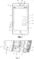
- FIG. 1 there is shown a front view of an apparatus 10 incorporating features of an example embodiment.
- a front view of an apparatus 10 incorporating features of an example embodiment.
- the features will be described with reference to the example embodiments shown in the drawings, it should be understood that features can be embodied in many alternate forms of embodiments.
- any suitable size, shape or type of elements or materials could be used.
- components of the apparatus 10 include a front housing member 30, a speaker box 34, a frame member 36, and a printed wiring board 21.
- the front housing member 30 includes holes 40, 42 for the speaker box 34 and an earpiece 44, respectively.
- the speaker box forms an enclosure which may prevent sound waves generated by the rearward-facing surface of the diaphragm interacting with sound waves generated at the front of the driver. Because the forward- and rearward-generated sounds are out of phase with each other, any interaction between the two in the listening space may creates a distortion of the original signal as it was intended to be reproduced.
- the speaker box may also plays a role in managing vibration induced by the driver frame and moving airmass within the enclosure, as well as heat generated by driver voice coils.
- the speaker box 34 in this example embodiment, is formed with a casing member 38 which is a molded interconnect device (MID).
- MID is an injection-molded thermoplastic part with integrated electronic circuit traces.
- LDS Laser Direct Structuring
- other types of molding or trace forming could be used.
- the speaker box 34 in this example embodiment generally comprises a magnet system 46, a diaphragm 47, a coil 48 and frame components 38, 50, 52.
- the components 38, 50, 52 are used to locate the magnet system 46, diaphragm 47 and coil 48 relative to each other, to attach the magnet system 46, diaphragm 47 and coil 48 to other frame components of the housing 12, and to provide a speaker box function for the speaker.
- the back lid 52 of the speaker box may be provided by the frame member 36 with proper sealing elements, such as a gasket for example.
- the frame member 50 houses the magnet system 46 in the aperture 54.
- the diaphragm 47 is attached to the perimeter rim 56 or front lid 38.
- the coil 48 is attached to the diaphragm 47.
- Holes 58 are provided in the frame member 50 for the spring contacts 60. Solder pads 62 are provided on the frame 58 to connect the leads 64 of the coil 48 to the spring contacts 60.
- any suitable speaker system could be provided including, for example, with a piezoelectric drive or an electrostatic drive, such as for a piezoelectric speaker or a electrostatic speaker, or with a non-permanent electromagnet.
- the casing member 38 comprises two electrical conductors 66, 68 which are integrally formed on the casing member by the LDS process.
- the electrical conductors 66, 68 are shown without the casing member merely for the sake of clarity.
- the electrical conductors 66, 68 are speaker wiring to electrically connect the leads 64 of the coil 48 to another component.
- the leads 64 are connected to the solder pads 62, and the contact springs 60 connected the solder pads 62 to the electrical conductors 66, 68.
- the electrical conductors 66, 68 each comprise a first end 70, an opposite second end 72, and a middle section 74 between the first and second ends 70, 72.
- the first and second ends 70, 72 form contact pads on the inside surface of the casing member 38.
- the middle sections 74 are located on the opposite outer side of the casing member 38. Vias 76 are provided through the casing member 38 from the first ends 70 to the middle sections 74.
- the middle sections 74 wrap over the side edge 78 from the middle sections 74 to the second ends 72.
- different wiring patters could be provided.
- Fig. 3 The components shown in Fig. 3 are assembled as a unified sub-assembly which is able to be attached to other components of the apparatus as a module.
- the contact pads formed by the second ends 72 connect to contact areas 80 of the PWB 21 to automatically electrical connect the coil 48 to the PWB 21.
- a speaker box is becoming an industry trend in mobile communications devices with thinner design trends, such as in smartphones, tablet computers, phabets, etc.
- FPC flexible printed circuit
- Traditional coil connectivity often comprises a complex assembly process, and has additional materials cost for FPC or insert metal or soldering cable.
- an insert metal traditional connectivity comprising stainless steel sheets may be used as the connection material with gold plating on it. This type of connection will usually require a flat surface because of insert metal process limitation.
- a FPC traditional connectivity compared with stainless steel, will be more flexible regarding the speaker box surface. However, it is more expensive than insert metal. Also, sometimes the adhesive or heat stamping process to attach the FPC will also have additional costs and reliability risks.
- LDS technology allows for use of LDS technology as the connectivity between a speaker coil 48 and contact pads 72 on a speaker box. As further described below, this may be used with an LDS antenna on the speaker box as well. With features as described herein, there will be no additional cost for connectivity in contrast with FPC or cable connectivity.
- the flexibility of LDS technology as used for the speaker connectivity may also be used to provide a better antenna performance. Also, the flexibility will have no limitation on the speaker box surface design, and help design more beautiful curves.
- the conductors 66, 68 may go along the speaker box surface to the pads 72 which may contact C-clips on the PWB 21 provided as the contact areas 80. This may provide a flexible design on a 3D curve compared with traditional FPC design.
- the pads 72 can be formed together with the conductors 66, 68 with LDS technology, or the pads 72 may be done separately from the LDS process.
- the first pads 70 may be formed together with the conductors 66, 68 with LDS technology, or the pads 70 may be done separately from the LDS process.
- the speaker box may also be the carrier of the antenna pattern (s) .
- the casing member 38' includes the electrical conductors 66, 68 for the speaker and also the antenna pattern 82. If one or more antenna pattern 82 is formed on the casing 38 by the LDS process, the LDS process may be used at the same time to make both the electrical conductors 66, 68 and the antenna pattern 82. This means that the speaker box conductors 66, 68 and the antenna pattern 82 may be made in the same process.
- the speaker conductors 66, 68 may also be used as part of the antenna pattern, or part of the antenna parasitics. This may be used to get better antenna performance. In this case, proper decoupling and coupling components may be selected.
- a coupling 84 is shown between each of the conductors 66, 68 and two of the antenna patterns 82.
- the couplings 84 may comprise coupling capacitors for example.
- a decoupling 86 is shown between each of the conductors 66, 68 and the pads 62
- a decoupling 88 is shown between each of the conductors 66, 68 and the audio components connected to the PWB 21.
- the decouplings 86, 88 may be inductors for example.
- Passive components such as capacitors 84 and inductors 86, 88 for example, may be located on the PWB 21 and/or on or in the speaker box.
- the coupling capacitors 84 may be on PWB 21 for example.
- Decoupling components for the antenna arrangement may be used to eliminate interferences from the antenna functionality/performance (or isolate the antenna). In terms of the audio side, similar passive components may be used.
- Fig. 6 shows how a reusement between the speaker conductors 66, 68 and the antenna pattern 82 as an antenna function.
- Decoupling inductors 86, 88 are connected at both sides of speaker conductors 66, 68.
- the inductor value selection (such as 30 ⁇ 100 nH for example) allows the audio signal to pass (such as between about 20 ⁇ 20000 Hz for example), but isolates the RF frequency signal (about 0.9 ⁇ 2.5 GHz for example).
- the coupling capacitor (such as about 10 ⁇ 50 pF for example) will allow the RF signal to pass, but it will be so small that audio signal will not pass. So they will not impact each other when both functions are working at a same time.
- Features as described herein may provide a flexible speaker wiring design and no additional cost if the speaker wiring design is manufactured at the same time and with the same process as the manufacture of the antenna design is manufactured.
- Features as described herein may provide a more flexible antenna design; perhaps with coupling to the speaker electrical conductors.
- LDS liquid crystal display
- an apparatus comprising a sound transducer; a casing member, where the sound transducer is mounted to the casing member, and where the casing member is configured to at least partially form a speaker box; and electrical conductors integrally formed with the casing member, where the electrical conductors are electrically connected to the sound transducer, and where the electrical conductors are configured to electrically connect the sound transducer to a second member.
- the casing member may be a single part, but in alternative embodiments it could be formed using separate parts where these separate parts could accommodate the electrical conductors.
- the casing member could comprise a pot like part and a lid, wherein the pot and lid are ultrasonically welded, glued and/or heat-staked together during the manufacturing of the part.
- mounted may mean that the speaker is positioned or located within the casing member.
- the speaker may be integrally formed inside the casing, i.e. the chassis of the speaker may be formed by the casing, but in some designs the speaker may be positioned inside an aperture being formed inside the casing where speaker drops or fits into.
- An adhesive or gasket material may be used between the speaker and the aperture of the casing.
- the casing member may be formed by two or more different parts which could be ultrasonically welded together for example.
- the casing member may be formed by separate members (parts) which function together to enclose the speaker component and acoustic volumes for the speaker component.
- the speaker component may be positioned in a speaker aperture formed inside one part of the casing member that receives the speaker, and the electrical conductors could be located on another one of the casing member parts.
- the sound transducer may comprise a coil, and where the electrical conductors are connected to leads of the coil.
- the electrical conductors may comprise first and second opposite ends which are located on a first side of the casing member, and the electrical conductors may comprise a middle section located on a different second side of the casing member.
- the electrical conductors may be integral with the casing member by a Laser Direct Structuring (LDS) process.
- the apparatus may further comprise an antenna integrally formed with the casing member.
- the antenna may be integral with the casing member by a Laser Direct Structuring (LDS) process.
- the apparatus may further comprise an antenna integrally formed with the casing member.
- the apparatus may further comprise at least one coupling which couples at the antenna to at least one of the electrical conductors.
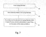
- an example method may comprise forming a casing member as illustrated by block 90, forming an antenna pattern on the casing member as illustrated by block 92, and forming electrical conductors on the same casing member as illustrated by block 94.
- the casing member may be a part of a speaker box.
- the antenna pattern and the electrical conductors may be formed by a same process, such as LDS for example. Because the antenna pattern and the electrical conductors may be formed by a same process, the antenna pattern and the electrical conductors may be formed at substantially a same time with the same process. Thus, no additional electrical conductivity for connecting the speaker to a PWB is needed.
- the electrical conductors may be integrally formed on the casing member with a Laser Direct Structuring (LDS) process.
- the first and second ends may be located on a first side of the casing member, and the electrical conductors may comprise a middle section located on a different second side of the casing member.
- the method may further comprise integrally forming an antenna on the casing member.
- the antenna may be integrally formed on the casing member with a Laser Direct Structuring (LDS) process.
- the method may further comprise coupling the antenna to at least one of the electrical conductors.
- the method may further comprise decoupling the electrical conductors from the sound transducer and/or the second member.
- the electrical conductors and the antenna may be integral with the casing member by a Laser Direct Structuring (LDS) process.
- Majorities of the electrical conductors and the antenna may be located on a first side of the casing member, and contact areas of the electrical conductors and the antenna may be located on an opposite second side of the casing member.
- LDS Laser Direct Structuring
Landscapes
- Engineering & Computer Science (AREA)
- Signal Processing (AREA)
- Computer Networks & Wireless Communication (AREA)
- Physics & Mathematics (AREA)
- Acoustics & Sound (AREA)
- Telephone Set Structure (AREA)
- Details Of Audible-Bandwidth Transducers (AREA)
Claims (15)
- Vorrichtung, umfassend:einen Schallwandler;ein Gehäuseelement (38),wobei der Schallwandler an dem Gehäuseelement befestigt ist, und wobei das Gehäuseelement so konfiguriert ist, dass es zumindest teilweise ein Gehäuse für den Schallwandler bildet;eine Antenne (82), die integral mit dem Gehäuseelement ausgebildet ist, wobei die Antenne ein Antennenmuster bildet;mindestens zwei elektrische Leiterverdrahtungen (66, 68), die integral mit dem Gehäuseelement ausgebildet sind, wobei die mindestens zwei elektrischen Leiterverdrahtungen elektrisch mit dem Schallwandler verbunden sind; undmindestens eine Kopplungskomponente (84), die so konfiguriert ist, dass sie die Antenne mit mindestens einer der mindestens zwei elektrischen Leiterverdrahtungen koppelt, wobei die mindestens zwei elektrischen Leiterverdrahtungen so konfiguriert sind, dass sie eine elektrische Konnektivität für den Schallwandler bereitstellen, wobei die mindestens eine der mindestens zwei elektrischen Leiterverdrahtungen so konfiguriert ist, dass sie mit dem Antennenmuster koppelt ist, um mindestens einen Teil einer Antennenanordnung zu bilden.
- Vorrichtung nach Anspruch 1, wobei der Schallwandler eine Spule (48) umfasst, die mindestens zwei elektrischen Leiterverdrahtungen mit Leitungen der Spule verbunden sind und die mindestens eine der mindestens zwei elektrischen Leiterverdrahtungen mit dem Antennenmuster verbunden ist.
- Vorrichtung nach einem der Ansprüche 1 und 2, wobei die mindestens zwei elektrischen Leiterverdrahtungen erste und zweite gegenüberliegende Enden (70, 72) aufweisen, die sich auf einer ersten Seite des Gehäuseelements befinden.
- Vorrichtung nach Anspruch 3, wobei die mindestens zwei elektrischen Leiterverdrahtungen einen mittleren Abschnitt (74) umfassen, der sich auf einer anderen zweiten Seite des Gehäuseelements befindet.
- Vorrichtung nach einem der vorstehenden Ansprüche, wobei die mindestens zwei elektrischen Leiterverdrahtungen durch ein Laser-Direkt-Strukturierungsverfahren, LDS, integral mit dem Gehäuseelement ausgebildet sind.
- Vorrichtung nach einem der Ansprüche 1 und 5, ferner umfassend mindestens eine Entkopplungskomponente (86, 88), die so konfiguriert ist, dass sie die mindestens zwei elektrischen Leiterverdrahtungen von dem Schallwandler und/oder einem zweiten Element entkoppelt.
- Vorrichtung nach einem der vorstehenden Ansprüche, ferner umfassend:eine Leiterplatte (21), die mit den mindestens zwei elektrischen Leiterverdrahtungen verbunden ist;eine elektrische Anzeige (14), die mit der Leiterplatte verbunden ist;einen Empfänger (16), der mit der Leiterplatte verbunden ist;einen Sender (18), der mit der Leiterplatte verbunden ist;einen Prozessor (22), die mit der Leiterplatte verbunden ist;einen Speicher (24), der mit der Leiterplatte verbunden ist; undeine Batterie (26), die mit der Leiterplatte verbunden ist.
- Vorrichtung nach einem der vorstehenden Ansprüche, wobei das Gehäuseelement so konfiguriert ist, dass es zumindest teilweise eine Lautsprecherbox(34) für den Schallwandler bildet.
- Vorrichtung nach Anspruch 8, wobei die Lautsprecherbox durch eines der folgenden Elemente gebildet wird:
zwei oder mehr verschiedene Teile, die zusammenwirken, um die Lautsprecherkomponente und die akustischen Volumina für die Lautsprecherkomponente zu umschließen; und ein einzelnes Teil, das mindestens eines der folgenden Merkmale aufweist: ultraschallverschweißt, verklebt und wärmeverbunden. - Verfahren zur Bereitstellung einer Vorrichtung, umfassend:Bereitstellen eines Schallwandlers;Bereitstellen eines Gehäuseelements (38);Befestigen des Schallwandlers an dem Gehäuseelement, und wobei das Gehäuseelement so konfiguriert ist, dass es zumindest teilweise ein Gehäuse für den Schallwandler bildet;Bereitstellen einer Antenne (82), die integral mit dem Gehäuseelement ausgebildet ist, wobei die Antenne ein Antennenmuster bildet;Bereitstellen von mindestens zwei elektrischen Leiterverdrahtungen (66, 68), die integral mit dem Gehäuseelement ausgebildet sind;elektrisches Verbinden der mindestens zwei elektrischen Leiterverdrahtungen mit dem Schallwandler; undKoppeln der Antenne mit Hilfe mindestens einer Kopplungskomponente (84) mit mindestens einer der mindestens zwei elektrischen Leiterverdrahtungen;Bereitstellen elektrischer Konnektivität für den Schallwandler unter Verwendung der mindestens zwei elektrischen Leiterverdrahtungen; undKoppeln mindestens einer der mindestens zwei elektrischen Leiterverdrahtungen mit dem Antennenmuster, um mindestens einen Teil einer Antennenanordnung zu bilden.
- Verfahren nach Anspruch 10, wobei der Schallwandler eine Spule (48) umfasst, wobei das Verfahren ferner umfasst:Verbinden der mindestens zwei elektrischen Leiterverdrahtungen mit Leitern der Spule; undVerbinden der mindestens einen der mindestens zwei elektrischen Leiterverdrahtungen mit dem Antennenmuster.
- Verfahren nach einem der Ansprüche 10 und 11, wobei das Bereitstellen der mindestens zwei elektrischen Leiterverdrahtungen das Anordnen erster und zweiter gegenüberliegende Enden (70, 72) auf einer ersten Seite des Gehäuseelements umfasst.
- Verfahren nach Anspruch 12, wobei das Bereitstellen der mindestens zwei elektrischen Leiterverdrahtungen das Bereitstellen eines mittleren Abschnitts (74) umfasst, der sich auf einer anderen zweiten Seite des Gehäuseelements befindet.
- Verfahren nach einem der Ansprüche 10 bis 13, wobei das Bereitstellen der mindestens zwei elektrischen Leiterverdrahtungen das Bereitstellen der mindestens zwei elektrischen Leiterverdrahtungen integral mit dem Gehäuseelement durch ein Laser-Direkt-Strukturierungsverfahren, LDS, umfasst.
- Verfahren nach einem der Ansprüche 10 und 14, ferner umfassend das Bereitstellen mindestens einer Entkopplungskomponente (86, 88), die so konfiguriert ist, dass sie die mindestens zwei elektrischen Leiterverdrahtungen von dem Schallwandler und/oder einem zweiten Element entkoppelt.
Applications Claiming Priority (1)
| Application Number | Priority Date | Filing Date | Title |
|---|---|---|---|
| PCT/CN2013/089217 WO2015085539A1 (en) | 2013-12-12 | 2013-12-12 | Speaker casing with integrally formed electrical conductors |
Publications (3)
| Publication Number | Publication Date |
|---|---|
| EP3081002A1 EP3081002A1 (de) | 2016-10-19 |
| EP3081002A4 EP3081002A4 (de) | 2017-07-26 |
| EP3081002B1 true EP3081002B1 (de) | 2021-05-26 |
Family
ID=53370498
Family Applications (1)
| Application Number | Title | Priority Date | Filing Date |
|---|---|---|---|
| EP13899223.5A Active EP3081002B1 (de) | 2013-12-12 | 2013-12-12 | Lautsprechergehäuse mit angeformten elektrischen leitern |
Country Status (4)
| Country | Link |
|---|---|
| US (1) | US9948342B2 (de) |
| EP (1) | EP3081002B1 (de) |
| CN (1) | CN106416288B (de) |
| WO (1) | WO2015085539A1 (de) |
Families Citing this family (13)
| Publication number | Priority date | Publication date | Assignee | Title |
|---|---|---|---|---|
| US9948324B1 (en) * | 2011-01-31 | 2018-04-17 | Open Invention Network, Llc | System and method for informational reduction |
| US10191796B1 (en) | 2011-01-31 | 2019-01-29 | Open Invention Network, Llc | System and method for statistical application-agnostic fault detection in environments with data trend |
| CN104168528B (zh) * | 2014-09-01 | 2018-09-18 | 歌尔股份有限公司 | 扬声器模组 |
| US20160363367A1 (en) * | 2015-06-12 | 2016-12-15 | General Electric Company | Component for a refrigerator appliance having an integrated heater |
| CN105141717B (zh) * | 2015-07-31 | 2019-07-26 | 瑞声光电科技(苏州)有限公司 | 移动终端设备 |
| US20170099536A1 (en) * | 2015-10-06 | 2017-04-06 | Sound Solutions International Co., Ltd. | Electroacoustic transducer with flexible coilwire connection |
| US11069962B2 (en) | 2018-12-20 | 2021-07-20 | Motorola Solutions, Inc. | Antenna assembly for portable radio |
| CN211630640U (zh) * | 2020-02-19 | 2020-10-02 | Oppo广东移动通信有限公司 | 固定组件及电子设备 |
| KR102863219B1 (ko) | 2020-09-24 | 2025-09-23 | 삼성전자 주식회사 | 전자 장치 |
| CN213938240U (zh) * | 2020-11-30 | 2021-08-10 | 瑞声科技(新加坡)有限公司 | 一种扬声器箱及移动终端 |
| CN112468907B (zh) * | 2020-12-18 | 2022-03-01 | 瑞声新能源发展(常州)有限公司科教城分公司 | 扬声器箱 |
| CN113782968A (zh) * | 2021-08-25 | 2021-12-10 | 联宝(合肥)电子科技有限公司 | 内置喇叭组件、内置喇叭组件制作工艺及电子装置 |
| WO2023101466A1 (ko) * | 2021-12-01 | 2023-06-08 | 삼성전자 주식회사 | 전자 장치 및 노이즈 감소 방법 |
Family Cites Families (17)
| Publication number | Priority date | Publication date | Assignee | Title |
|---|---|---|---|---|
| DE10052909A1 (de) * | 2000-10-25 | 2002-05-08 | Siemens Ag | Kommunikationsendgerät |
| SE0301760L (sv) * | 2003-06-17 | 2004-12-18 | Perlos Ab | Moduluppbyggd terminalanordning |
| JP4300210B2 (ja) * | 2004-11-18 | 2009-07-22 | 株式会社カシオ日立モバイルコミュニケーションズ | 携帯型無線機 |
| KR100668423B1 (ko) * | 2005-03-14 | 2007-01-16 | 삼성전자주식회사 | 안테나 성능 개선을 위한 휴대용 무선단말기의 스피커 장치 |
| US7483727B2 (en) * | 2005-04-04 | 2009-01-27 | Research In Motion Limited | Mobile wireless communications device having improved antenna impedance match and antenna gain from RF energy |
| CN101138131A (zh) * | 2006-05-10 | 2008-03-05 | 日本莱尔德技术株式会社 | 天线模块及无线通信终端 |
| US20090061966A1 (en) * | 2007-09-05 | 2009-03-05 | Motorola, Inc. | Antenna and speaker assembly |
| US8150091B2 (en) * | 2007-12-14 | 2012-04-03 | Sony Ericsson Mobile Communications Ab | Printed circuit board for a flat-panel speaker |
| US7933123B2 (en) * | 2008-04-11 | 2011-04-26 | Apple Inc. | Portable electronic device with two-piece housing |
| US8260343B2 (en) * | 2008-11-06 | 2012-09-04 | Sony Ericsson Mobile Communications Ab | Electronic devices including vertically mounted loudspeakers and related assemblies and methods |
| FI20105158A7 (fi) * | 2010-02-18 | 2011-08-19 | Pulse Finland Oy | Kuorisäteilijällä varustettu antenni |
| CN102244830B (zh) * | 2010-05-13 | 2013-09-25 | 信维创科通信技术(北京)有限公司 | 一种声学模组及其制备方法以及具有声学模组的设备 |
| US8427817B2 (en) * | 2010-10-15 | 2013-04-23 | Roche Diagnostics Operations, Inc. | Handheld diabetes manager with touch screen display |
| US8848104B2 (en) | 2010-12-17 | 2014-09-30 | Telegent Systems, Inc. | Whip antenna for mobile communication devices |
| TWM422838U (en) | 2011-09-21 | 2012-02-11 | Wistron Neweb Corp | Speaker module and electronic apparatus thereof |
| CN103531905A (zh) * | 2012-07-06 | 2014-01-22 | 宏碁股份有限公司 | 电子装置 |
| CN103208677A (zh) * | 2013-03-30 | 2013-07-17 | 东莞劲胜精密组件股份有限公司 | 一种印刷天线 |
-
2013
- 2013-12-12 EP EP13899223.5A patent/EP3081002B1/de active Active
- 2013-12-12 WO PCT/CN2013/089217 patent/WO2015085539A1/en not_active Ceased
- 2013-12-12 CN CN201380081988.2A patent/CN106416288B/zh not_active Expired - Fee Related
- 2013-12-12 US US15/102,337 patent/US9948342B2/en active Active
Non-Patent Citations (1)
| Title |
|---|
| None * |
Also Published As
| Publication number | Publication date |
|---|---|
| WO2015085539A1 (en) | 2015-06-18 |
| EP3081002A4 (de) | 2017-07-26 |
| US20160323003A1 (en) | 2016-11-03 |
| CN106416288A (zh) | 2017-02-15 |
| CN106416288B (zh) | 2019-11-08 |
| US9948342B2 (en) | 2018-04-17 |
| EP3081002A1 (de) | 2016-10-19 |
Similar Documents
| Publication | Publication Date | Title |
|---|---|---|
| EP3081002B1 (de) | Lautsprechergehäuse mit angeformten elektrischen leitern | |
| CN103972637B (zh) | 用于便携式终端的天线设备 | |
| US8532722B2 (en) | Folded flex assembly for personal media device | |
| KR102002874B1 (ko) | 휴대용 단말기의 안테나 장치 | |
| US6879849B2 (en) | In-built antenna for mobile communication device | |
| US20150117681A1 (en) | Acoustic Assembly and Method of Manufacturing The Same | |
| US9167324B2 (en) | Speaker module for portable terminal | |
| AU2013270534B2 (en) | Terminal having speaker and method of manufacturing the same | |
| JP3987419B2 (ja) | スピーカ一体型アンテナ、スピーカ一体型アンテナの実装構造、電子機器及びスピーカ一体型アンテナの実装方法 | |
| US10027021B2 (en) | Three-dimensional antenna apparatus | |
| US8135433B2 (en) | Reduction in interference between components | |
| CN213126091U (zh) | 一种电子设备 | |
| US20060079105A1 (en) | Devices and methods for creating an electrical connection | |
| WO2018216556A1 (ja) | 電子機器 | |
| KR100700575B1 (ko) | 이동통신 단말기의 적층형 회로기판 | |
| JP6665081B2 (ja) | 電子機器 | |
| KR101681902B1 (ko) | 안테나 구조체 | |
| JP2005020766A (ja) | 携帯無線機 | |
| CN211656371U (zh) | 音频播放模组及电子设备 | |
| KR101312251B1 (ko) | 휴대 단말기 | |
| CN107623884B (zh) | 线控结构及蓝牙耳机 | |
| KR101782955B1 (ko) | 안테나 구조체 | |
| EP2720314B1 (de) | Antennenumwickelung um eine Lautsprecherklappe |
Legal Events
| Date | Code | Title | Description |
|---|---|---|---|
| PUAI | Public reference made under article 153(3) epc to a published international application that has entered the european phase |
Free format text: ORIGINAL CODE: 0009012 |
|
| 17P | Request for examination filed |
Effective date: 20160706 |
|
| AK | Designated contracting states |
Kind code of ref document: A1 Designated state(s): AL AT BE BG CH CY CZ DE DK EE ES FI FR GB GR HR HU IE IS IT LI LT LU LV MC MK MT NL NO PL PT RO RS SE SI SK SM TR |
|
| AX | Request for extension of the european patent |
Extension state: BA ME |
|
| DAX | Request for extension of the european patent (deleted) | ||
| REG | Reference to a national code |
Ref country code: DE Ref legal event code: R079 Ref document number: 602013077710 Country of ref document: DE Free format text: PREVIOUS MAIN CLASS: H04R0001040000 Ipc: H04R0001060000 |
|
| A4 | Supplementary search report drawn up and despatched |
Effective date: 20170626 |
|
| RIC1 | Information provided on ipc code assigned before grant |
Ipc: H01Q 1/46 20060101ALI20170620BHEP Ipc: H01Q 1/24 20060101ALI20170620BHEP Ipc: H04M 1/03 20060101ALI20170620BHEP Ipc: H04R 1/06 20060101AFI20170620BHEP Ipc: H01Q 1/38 20060101ALI20170620BHEP |
|
| RAP1 | Party data changed (applicant data changed or rights of an application transferred) |
Owner name: NOKIA TECHNOLOGIES OY |
|
| STAA | Information on the status of an ep patent application or granted ep patent |
Free format text: STATUS: EXAMINATION IS IN PROGRESS |
|
| 17Q | First examination report despatched |
Effective date: 20191206 |
|
| GRAP | Despatch of communication of intention to grant a patent |
Free format text: ORIGINAL CODE: EPIDOSNIGR1 |
|
| STAA | Information on the status of an ep patent application or granted ep patent |
Free format text: STATUS: GRANT OF PATENT IS INTENDED |
|
| INTG | Intention to grant announced |
Effective date: 20201218 |
|
| GRAS | Grant fee paid |
Free format text: ORIGINAL CODE: EPIDOSNIGR3 |
|
| GRAA | (expected) grant |
Free format text: ORIGINAL CODE: 0009210 |
|
| STAA | Information on the status of an ep patent application or granted ep patent |
Free format text: STATUS: THE PATENT HAS BEEN GRANTED |
|
| AK | Designated contracting states |
Kind code of ref document: B1 Designated state(s): AL AT BE BG CH CY CZ DE DK EE ES FI FR GB GR HR HU IE IS IT LI LT LU LV MC MK MT NL NO PL PT RO RS SE SI SK SM TR |
|
| REG | Reference to a national code |
Ref country code: GB Ref legal event code: FG4D |
|
| REG | Reference to a national code |
Ref country code: CH Ref legal event code: EP |
|
| REG | Reference to a national code |
Ref country code: DE Ref legal event code: R096 Ref document number: 602013077710 Country of ref document: DE |
|
| REG | Reference to a national code |
Ref country code: AT Ref legal event code: REF Ref document number: 1397428 Country of ref document: AT Kind code of ref document: T Effective date: 20210615 |
|
| REG | Reference to a national code |
Ref country code: IE Ref legal event code: FG4D |
|
| REG | Reference to a national code |
Ref country code: NL Ref legal event code: FP |
|
| REG | Reference to a national code |
Ref country code: LT Ref legal event code: MG9D |
|
| REG | Reference to a national code |
Ref country code: AT Ref legal event code: MK05 Ref document number: 1397428 Country of ref document: AT Kind code of ref document: T Effective date: 20210526 |
|
| PG25 | Lapsed in a contracting state [announced via postgrant information from national office to epo] |
Ref country code: AT Free format text: LAPSE BECAUSE OF FAILURE TO SUBMIT A TRANSLATION OF THE DESCRIPTION OR TO PAY THE FEE WITHIN THE PRESCRIBED TIME-LIMIT Effective date: 20210526 Ref country code: BG Free format text: LAPSE BECAUSE OF FAILURE TO SUBMIT A TRANSLATION OF THE DESCRIPTION OR TO PAY THE FEE WITHIN THE PRESCRIBED TIME-LIMIT Effective date: 20210826 Ref country code: FI Free format text: LAPSE BECAUSE OF FAILURE TO SUBMIT A TRANSLATION OF THE DESCRIPTION OR TO PAY THE FEE WITHIN THE PRESCRIBED TIME-LIMIT Effective date: 20210526 Ref country code: LT Free format text: LAPSE BECAUSE OF FAILURE TO SUBMIT A TRANSLATION OF THE DESCRIPTION OR TO PAY THE FEE WITHIN THE PRESCRIBED TIME-LIMIT Effective date: 20210526 Ref country code: HR Free format text: LAPSE BECAUSE OF FAILURE TO SUBMIT A TRANSLATION OF THE DESCRIPTION OR TO PAY THE FEE WITHIN THE PRESCRIBED TIME-LIMIT Effective date: 20210526 |
|
| PG25 | Lapsed in a contracting state [announced via postgrant information from national office to epo] |
Ref country code: SE Free format text: LAPSE BECAUSE OF FAILURE TO SUBMIT A TRANSLATION OF THE DESCRIPTION OR TO PAY THE FEE WITHIN THE PRESCRIBED TIME-LIMIT Effective date: 20210526 Ref country code: RS Free format text: LAPSE BECAUSE OF FAILURE TO SUBMIT A TRANSLATION OF THE DESCRIPTION OR TO PAY THE FEE WITHIN THE PRESCRIBED TIME-LIMIT Effective date: 20210526 Ref country code: PL Free format text: LAPSE BECAUSE OF FAILURE TO SUBMIT A TRANSLATION OF THE DESCRIPTION OR TO PAY THE FEE WITHIN THE PRESCRIBED TIME-LIMIT Effective date: 20210526 Ref country code: PT Free format text: LAPSE BECAUSE OF FAILURE TO SUBMIT A TRANSLATION OF THE DESCRIPTION OR TO PAY THE FEE WITHIN THE PRESCRIBED TIME-LIMIT Effective date: 20210927 Ref country code: NO Free format text: LAPSE BECAUSE OF FAILURE TO SUBMIT A TRANSLATION OF THE DESCRIPTION OR TO PAY THE FEE WITHIN THE PRESCRIBED TIME-LIMIT Effective date: 20210826 Ref country code: IS Free format text: LAPSE BECAUSE OF FAILURE TO SUBMIT A TRANSLATION OF THE DESCRIPTION OR TO PAY THE FEE WITHIN THE PRESCRIBED TIME-LIMIT Effective date: 20210926 Ref country code: GR Free format text: LAPSE BECAUSE OF FAILURE TO SUBMIT A TRANSLATION OF THE DESCRIPTION OR TO PAY THE FEE WITHIN THE PRESCRIBED TIME-LIMIT Effective date: 20210827 Ref country code: LV Free format text: LAPSE BECAUSE OF FAILURE TO SUBMIT A TRANSLATION OF THE DESCRIPTION OR TO PAY THE FEE WITHIN THE PRESCRIBED TIME-LIMIT Effective date: 20210526 |
|
| PG25 | Lapsed in a contracting state [announced via postgrant information from national office to epo] |
Ref country code: RO Free format text: LAPSE BECAUSE OF FAILURE TO SUBMIT A TRANSLATION OF THE DESCRIPTION OR TO PAY THE FEE WITHIN THE PRESCRIBED TIME-LIMIT Effective date: 20210526 Ref country code: ES Free format text: LAPSE BECAUSE OF FAILURE TO SUBMIT A TRANSLATION OF THE DESCRIPTION OR TO PAY THE FEE WITHIN THE PRESCRIBED TIME-LIMIT Effective date: 20210526 Ref country code: SK Free format text: LAPSE BECAUSE OF FAILURE TO SUBMIT A TRANSLATION OF THE DESCRIPTION OR TO PAY THE FEE WITHIN THE PRESCRIBED TIME-LIMIT Effective date: 20210526 Ref country code: SM Free format text: LAPSE BECAUSE OF FAILURE TO SUBMIT A TRANSLATION OF THE DESCRIPTION OR TO PAY THE FEE WITHIN THE PRESCRIBED TIME-LIMIT Effective date: 20210526 Ref country code: DK Free format text: LAPSE BECAUSE OF FAILURE TO SUBMIT A TRANSLATION OF THE DESCRIPTION OR TO PAY THE FEE WITHIN THE PRESCRIBED TIME-LIMIT Effective date: 20210526 Ref country code: EE Free format text: LAPSE BECAUSE OF FAILURE TO SUBMIT A TRANSLATION OF THE DESCRIPTION OR TO PAY THE FEE WITHIN THE PRESCRIBED TIME-LIMIT Effective date: 20210526 Ref country code: CZ Free format text: LAPSE BECAUSE OF FAILURE TO SUBMIT A TRANSLATION OF THE DESCRIPTION OR TO PAY THE FEE WITHIN THE PRESCRIBED TIME-LIMIT Effective date: 20210526 |
|
| REG | Reference to a national code |
Ref country code: DE Ref legal event code: R097 Ref document number: 602013077710 Country of ref document: DE |
|
| PLBE | No opposition filed within time limit |
Free format text: ORIGINAL CODE: 0009261 |
|
| STAA | Information on the status of an ep patent application or granted ep patent |
Free format text: STATUS: NO OPPOSITION FILED WITHIN TIME LIMIT |
|
| 26N | No opposition filed |
Effective date: 20220301 |
|
| PG25 | Lapsed in a contracting state [announced via postgrant information from national office to epo] |
Ref country code: IS Free format text: LAPSE BECAUSE OF FAILURE TO SUBMIT A TRANSLATION OF THE DESCRIPTION OR TO PAY THE FEE WITHIN THE PRESCRIBED TIME-LIMIT Effective date: 20210926 Ref country code: AL Free format text: LAPSE BECAUSE OF FAILURE TO SUBMIT A TRANSLATION OF THE DESCRIPTION OR TO PAY THE FEE WITHIN THE PRESCRIBED TIME-LIMIT Effective date: 20210526 |
|
| PG25 | Lapsed in a contracting state [announced via postgrant information from national office to epo] |
Ref country code: MC Free format text: LAPSE BECAUSE OF FAILURE TO SUBMIT A TRANSLATION OF THE DESCRIPTION OR TO PAY THE FEE WITHIN THE PRESCRIBED TIME-LIMIT Effective date: 20210526 Ref country code: IT Free format text: LAPSE BECAUSE OF FAILURE TO SUBMIT A TRANSLATION OF THE DESCRIPTION OR TO PAY THE FEE WITHIN THE PRESCRIBED TIME-LIMIT Effective date: 20210526 |
|
| REG | Reference to a national code |
Ref country code: CH Ref legal event code: PL |
|
| REG | Reference to a national code |
Ref country code: BE Ref legal event code: MM Effective date: 20211231 |
|
| PG25 | Lapsed in a contracting state [announced via postgrant information from national office to epo] |
Ref country code: LU Free format text: LAPSE BECAUSE OF NON-PAYMENT OF DUE FEES Effective date: 20211212 Ref country code: IE Free format text: LAPSE BECAUSE OF NON-PAYMENT OF DUE FEES Effective date: 20211212 |
|
| PG25 | Lapsed in a contracting state [announced via postgrant information from national office to epo] |
Ref country code: FR Free format text: LAPSE BECAUSE OF NON-PAYMENT OF DUE FEES Effective date: 20211231 Ref country code: BE Free format text: LAPSE BECAUSE OF NON-PAYMENT OF DUE FEES Effective date: 20211231 |
|
| PG25 | Lapsed in a contracting state [announced via postgrant information from national office to epo] |
Ref country code: LI Free format text: LAPSE BECAUSE OF NON-PAYMENT OF DUE FEES Effective date: 20211231 Ref country code: CH Free format text: LAPSE BECAUSE OF NON-PAYMENT OF DUE FEES Effective date: 20211231 |
|
| PG25 | Lapsed in a contracting state [announced via postgrant information from national office to epo] |
Ref country code: HU Free format text: LAPSE BECAUSE OF FAILURE TO SUBMIT A TRANSLATION OF THE DESCRIPTION OR TO PAY THE FEE WITHIN THE PRESCRIBED TIME-LIMIT; INVALID AB INITIO Effective date: 20131212 |
|
| PG25 | Lapsed in a contracting state [announced via postgrant information from national office to epo] |
Ref country code: CY Free format text: LAPSE BECAUSE OF FAILURE TO SUBMIT A TRANSLATION OF THE DESCRIPTION OR TO PAY THE FEE WITHIN THE PRESCRIBED TIME-LIMIT Effective date: 20210526 |
|
| P01 | Opt-out of the competence of the unified patent court (upc) registered |
Effective date: 20230527 |
|
| PGFP | Annual fee paid to national office [announced via postgrant information from national office to epo] |
Ref country code: NL Payment date: 20231116 Year of fee payment: 11 |
|
| PGFP | Annual fee paid to national office [announced via postgrant information from national office to epo] |
Ref country code: GB Payment date: 20231102 Year of fee payment: 11 |
|
| PG25 | Lapsed in a contracting state [announced via postgrant information from national office to epo] |
Ref country code: MK Free format text: LAPSE BECAUSE OF FAILURE TO SUBMIT A TRANSLATION OF THE DESCRIPTION OR TO PAY THE FEE WITHIN THE PRESCRIBED TIME-LIMIT Effective date: 20210526 |
|
| PG25 | Lapsed in a contracting state [announced via postgrant information from national office to epo] |
Ref country code: MT Free format text: LAPSE BECAUSE OF FAILURE TO SUBMIT A TRANSLATION OF THE DESCRIPTION OR TO PAY THE FEE WITHIN THE PRESCRIBED TIME-LIMIT Effective date: 20210526 |
|
| PGFP | Annual fee paid to national office [announced via postgrant information from national office to epo] |
Ref country code: DE Payment date: 20241029 Year of fee payment: 12 |
|
| REG | Reference to a national code |
Ref country code: NL Ref legal event code: MM Effective date: 20250101 |
|
| GBPC | Gb: european patent ceased through non-payment of renewal fee |
Effective date: 20241212 |
|
| PG25 | Lapsed in a contracting state [announced via postgrant information from national office to epo] |
Ref country code: NL Free format text: LAPSE BECAUSE OF NON-PAYMENT OF DUE FEES Effective date: 20250101 |
|
| PG25 | Lapsed in a contracting state [announced via postgrant information from national office to epo] |
Ref country code: GB Free format text: LAPSE BECAUSE OF NON-PAYMENT OF DUE FEES Effective date: 20241212 |
|
| PG25 | Lapsed in a contracting state [announced via postgrant information from national office to epo] |
Ref country code: TR Free format text: LAPSE BECAUSE OF FAILURE TO SUBMIT A TRANSLATION OF THE DESCRIPTION OR TO PAY THE FEE WITHIN THE PRESCRIBED TIME-LIMIT Effective date: 20210526 |