EP3081128A1 - Distributeur désinfectant avec un égouttoir - Google Patents
Distributeur désinfectant avec un égouttoir Download PDFInfo
- Publication number
- EP3081128A1 EP3081128A1 EP16165377.9A EP16165377A EP3081128A1 EP 3081128 A1 EP3081128 A1 EP 3081128A1 EP 16165377 A EP16165377 A EP 16165377A EP 3081128 A1 EP3081128 A1 EP 3081128A1
- Authority
- EP
- European Patent Office
- Prior art keywords
- grid
- collecting
- disinfectant liquid
- disinfecting device
- reservoir
- Prior art date
- Legal status (The legal status is an assumption and is not a legal conclusion. Google has not performed a legal analysis and makes no representation as to the accuracy of the status listed.)
- Granted
Links
Images


Classifications
-
- A—HUMAN NECESSITIES
- A47—FURNITURE; DOMESTIC ARTICLES OR APPLIANCES; COFFEE MILLS; SPICE MILLS; SUCTION CLEANERS IN GENERAL
- A47K—SANITARY EQUIPMENT; ACCESSORIES THEREFOR, e.g. TOILET ACCESSORIES
- A47K5/00—Holders or dispensers for soap, toothpaste or the like
- A47K5/06—Dispensers for soap
- A47K5/12—Dispensers for soap for liquid or pasty soap
Definitions
- the present invention relates to a disinfecting device comprising a collecting device configured to collect disinfectant liquid from a disinfecting device.
- disinfectant liquid as used herein is understood to mean a liquid, often in the form of a gel, with an alcohol percentage of more than 60%.
- Collecting devices for disinfectant liquid from disinfecting devices are generally known.
- Known collecting devices have a collecting surface on which disinfectant liquid dispensed or leaking from the disinfecting device is collected.
- the collecting surface may form part of a tray with upright edges, on which a cover plate provided with leak holes is positioned.
- a problem of the known collecting devices is that disinfectant liquid that falls on the collecting device from the disinfecting device remains present on the cover plate and continues to be exposed to the environment. This is undesirable in environments where use is made of disinfectant liquid in connection with contamination of the cover plate.
- a disinfecting device comprising a housing provided with a receiving space that is configured to accommodate a reservoir containing disinfectant liquid, a dispensing nozzle which is communicatively connected to a reservoir accommodated in the receiving space and which is configured to dispense disinfectant liquid, a valve device which, in non-actuated condition, interrupts the communication between the reservoir and the dispensing nozzle and which, in actuated condition, allows disinfectant liquid to flow from the reservoir to the dispensing nozzle and be dispensed by the dispensing nozzle, and a collecting device connected to the housing, which is disposed under a dispensing nozzle, which collecting device is configured to collect disinfectant liquid dispensed by the dispensing nozzle, the collecting device comprising a collecting reservoir provided with an at least substantially closed collecting surface and with a grid that is permeable to disinfectant liquid, which grid is located some distance above the collecting surface and which has a projection perpendicular to a plane that extends parallel to the grid, which projection covers at most 7
- the grid be at least 25% open, or in other words, comprise meshes. Because of the relatively open nature of the grid surface, disinfectant liquid that falls on the grid can easily pass through the grid and fall on the collecting surface whilst relatively small meshes are used. As a result, the visibility and/or accessibility of such remaining disinfectant liquid or residue is/are minimised. As a result of the relatively small mesh size, disinfectant liquid that has collected on the collecting surface is hidden from view, which makes the environment look hygienic. Because the disinfectant liquid is hidden from view, it is not necessary to remove leaked disinfectant liquid; the residue can be allowed to accumulate in the collecting device insofar as it does not evaporate. At first sight this may seem to be merely an optical improvement.
- the grid is durably connected, for example fused together, with the collecting reservoir. This has the advantageous effect that the grid cannot be damaged to the extent that it needs to be replaced.
- the collecting reservoir comprises three hingedly, i.e. pivotally, interconnected parts forming collecting surfaces.
- the advantage of this is that the two outer parts can slope upward relative to the centre part, so that the disinfectant liquid is led to the collecting surfaces. In this way an improved collection of the disinfectant liquid is ensured.
- the grid is fused together with the collecting reservoir at the location of its circumferential edges and at the location of two hinge lines so as to form the three hinged-together collecting surfaces.
- the inventor has realised that in order to prevent unevennesses, irregularities, in the grid, it will be practical to fuse the grid fused together with the collecting reservoir in any case at the location of the joints about which the collecting device can pivot. This prevents, among other things, the grid from exhibiting a convexity or similar irregularity at the location of the centre part.
- the grid will thus consist of three parts, each part defining a substantially straight plane.
- At least one spacer is provided, which spacer provides the spacing between the collecting surface and the grid.
- Such a spacing prevents capillary action of disinfectant liquid that has collected on the collecting surface, which would result in disinfectant liquid remaining in or on the grid yet.
- a sufficient distance apart for example of at least 5 mm, furthermore preferably at least 8 mm, will help to hide from view any disinfectant liquid that has collected on the collecting surface.
- the grid is made of a, preferably flexible, wire material.
- Wire material preferably in a thickness of at most 2.5 mm, furthermore preferably at most 1.5 mm, provides a surface from which disinfectant liquid will easily fall in the direction of the collecting surface. This adds to the extent to which disinfectant material collected by the collecting device will be inaccessible.
- the grid is preferably a mesh grid, or at any rate, at least 60%, furthermore preferably at least 80% of the grid area is made up of mesh. According to another possibility, the entire grid area consists of mesh. Mesh enhances the aforesaid advantageous properties of the grid.
- the size of the meshes of the mesh is preferably at least 1.5 mm 2 , furthermore preferably at least 2.5 mm 2 .
- the size of the meshes of the mesh is preferably at most 10 mm 2 , furthermore preferably at most 7 mm 2 . With these preferred sizes a good equilibrium is obtained between permeability to (residue of) disinfectant liquid on the one hand and masking capacity on other hand.
- the grid preferably comprises a fabric.
- a fabric combines the properties of wire material and/or mesh with a relatively regular pattern of meshes between the material of the fabric.
- the grid mainly comprises textile.
- textile provides an advantageous combination of initial absorption and permeability to disinfectant liquid and masking of the collecting surface.
- the material of the grid is relatively matt in comparison with the material of the collecting surface.
- the relatively matt material has a relatively impeding effect on the ingress of light between the grid and the collecting surface.
- the relatively low degree of mattness of the material (i.e. relatively glossy material) of the collecting surface corresponds to reflection properties of disinfectant liquid, so that the aforesaid properties help to mask disinfectant liquid that is present on the collecting surface.
- the collecting surface is lighter in colour than the grid.
- the grid is flexible, i.e. the grid can be bent so that it properly abuts the collecting surface, or at least a possible upright edge thereof.
- the collecting surface is preferably made of a shape-retaining material.
- the grid is preferably made of a material that absorbs disinfectant liquid. That is, disinfectant liquid can to a small extent be absorbed by the material. Materials that have such absorbing properties and that could be used for a grid, among which polymers and textile types, are known to the skilled person.
- the absorbing properties of the grid material ensure that also disinfectant liquid that has remained behind on the grid becomes inaccessible from the environment and/or is at least hidden from the users' view.
- the meshes of the grid may be relatively small, for example so small that disinfectant liquid will remain "stuck" in a mesh, so that (residue of) disinfectant liquid cannot easily fall onto a collecting surface.
- the grid is made of a material that absorbs disinfectant liquid
- the material will absorb disinfectant liquid that has fallen on the grid until the material is saturated.
- the force of gravity and communication through the material of the grid will then ensure that the disinfectant liquid can pass through the material of the grid and is transported to the collecting surface in this way. If the material does not become saturated, the absorbed disinfectant liquid will already be hidden from view, of course.
- disinfectant liquid that has fallen onto the collecting device will be permanently inaccessible from the environment, at least insofar as said liquid has fallen onto the collecting surface via the grid.
- the collecting device can be exchanged for an unused identical collecting device.
- disinfectant material is relatively volatile, any residue that has remained behind in the collecting device, for example in the form of a rehydrating substance, such as glycerol, can be easily removed along with the collecting device. This prevents the risk of contamination resulting from improper or inexpert use of the collecting device.
- the material of the collecting surface and the material of the grid are resistant against alcoholic disinfectant liquid.
- the resistance of the materials prevents the exterior of the collecting device being affected during use thereof in combination with a disinfecting device.
- a very good permeability to disinfectant liquid is provided with a device in which the horizontal cross-sectional area of the grid is at least 25%, furthermore preferably at least 40%, open.
- a more open structure of the grid may of course affect its ability to mask disinfectant material that is present on the collecting surface.
- Sufficient alternative measures for reducing said visibility are known to the skilled person, however. Think in this connection of two superposed grids or grid elements that extend at an angle relative to the vertical, seen in vertical direction.
- the collecting device is preferably freely positioned on a support in use.
- the support functions to position the collecting device, for example. Because the collecting device is freely positioned on the support, the collecting device can be easily exchanged for a comparable collecting device. Periodically exchanging the collecting device contributes to the hygiene of the environment in which the collecting device is present.
- the support forms part of a disinfecting device comprising a dispenser for disinfectant liquid.
- a dispensing nozzle and the collecting device of the disinfecting device in question will thus be correctly oriented relative to each other at all times.
- a vertical projection of the grid on a horizontal projection plane has a surface area of at least 100 cm 2 , preferably at least 150 cm 2 , even more preferably at least 200 cm 2 .
- a vertical projection of the grid on a horizontal projection plane has a surface area of at most 1000 cm 2 , preferably at least 800 cm 2 , furthermore preferably at least 750 cm 2 , the collecting device will remain relatively compact.
- the present invention relates to a disinfecting device comprising a housing provided with a receiving space that is configured to accommodate a reservoir containing disinfectant liquid, a dispensing nozzle which is communicatively connected to a reservoir accommodated in the receiving space and which is configured to dispense disinfectant liquid, a valve device which, in non-actuated condition, interrupts the communication between the reservoir and the dispensing nozzle and which, in actuated condition, allows disinfectant liquid to flow from the reservoir to the dispensing nozzle and be dispensed by the dispensing nozzle, and a collecting device connected to the housing according to the first aspect of the present invention.
- a disinfecting device is provided that exhibits the aforesaid advantageous aspects of the collecting device according to the invention.
- a hygienic solution is provided if contactless operation of the valve device is possible.
- a user can simply place his hands under the dispensing nozzle and over the collecting device, wherein the dispensing of disinfectant liquid is initiated by means of a motion or presence sensor, for example.
- the disinfecting device can be flexibly installed at any desired location.
- a disinfecting device may be configured for independent operation, i.e. without the necessity to connect the column to the electric mains and/or other supply or discharge channels.
- the location of the column can be freely selected in that case.
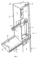
- figure 1 shows a perspective side view of a disinfection column 1, being an example of a disinfecting device according to the present invention.
- Figure 2 shows a vertical sectional view through the centre plane of the disinfection column 1 of figure 1 , which has a height of 150 cm.
- an upright 2 of hexagonal cross-section which is made of sheet metal and which comprises a front wall 3, two sidewalls 4, a rear wall 5 made up of two converging parts and a connecting piece, which are only partially shown in the figures, and a base 2a.
- a housing 6 of hexagonal cross-section which comprises a front wall 7, two sidewalls 8 and a three-part rear wall, which are likewise made of sheet metal.
- the shape of the upright 2 and the housing 6 is not particularly relevant for the use of the present invention.
- an outlet 10 Centrally located in the front wall 7 of the housing 6, at a height of 115 cm above the base 2a of the upright 2, is an outlet 10 in the form of a horizontally extending hollow tube of a plastic material such as PET which is resistant against alcoholic disinfectant liquid, wherein a motion sensor (not shown) and a dispensing nozzle 11 are provided at the underside, near the distal end of the outlet 10.
- the dispensing nozzle 11 is in contact with a reservoir 13 (not shown) via a conduit 12 extending through the outlet 10, in which reservoir a disinfectant liquid (not shown) is present.
- the reservoir 13 is an exchange reservoir, which is exchanged for a filled reservoir when the disinfectant liquid is (practically) used up.
- a supply line for supplying disinfectant liquid to the disinfection column from outside is not needed, and the column can function independently, which adds to the freedom of placement of the disinfection column 1.
- a lock 16 is provided for locking the housing against unwanted access.
- a collecting tray functioning as a collecting device for disinfectant liquid.
- the collecting tray 17 has a substantially V-shaped cross-section, comprising two sloping walls (not shown in the figures) which are interconnected at the bottom side by means of a horizontal connecting piece 19.
- a collecting reservoir 18 made up of three hinged-together collecting surfaces 18a, 18b, 18c is loosely provided on the sloping walls and the connecting piece.
- the sloping walls have a length of 17 cm (seen in the direction perpendicular to the longitudinal direction of the upright 2) and a width of 12.5 cm (seen in the direction of slope).
- the collecting tray 17 is bounded by the front wall 7 of the housing 6. Located at the distal end is an end wall 20.
- the collecting reservoir comprising collecting surfaces 18a, 18b, 18c is made of a material that is not affected by the disinfectant liquid, for example plastic plate material and plastic edges.
- FIG 3 shows a perspective side view of a collecting reservoir 61, which can be detachably placed in a collecting tray of a disinfection column according to the present invention.
- the collecting reservoir 61 comprises three parts forming collecting surfaces, which parts are hinged together by means of hinges 63 for movement in the directions indicated by arrows P.
- the central collecting part 62 is hingedly connected to two side parts 64 via hinges 63 (only one of which is partially shown in figure 3 ).
- the central collecting part 62 is provided with cross - shaped support means 65.
- the side parts 64 are provided with ribs 66.
- the collecting reservoir 61 is provided with a lip 67 on one side, which lip functions to enable easy removal of the collecting reservoir from a disinfecting device.
- Figure 3 shows a separate grid 68 in the form of a woven textile with a mesh width of 0.3 mm, which is attached to the outer edges of the parts of the collecting reservoir 61.
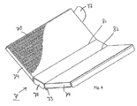
- Figure 4 shows a schematic side view of a composite collecting reservoir 71 for use with a disinfection column as shown in figure 1 .
- the elements are indicated by the same numerals as the comparable elements in figure 3 , augmented by 10.
- the collecting reservoir 71 is based on the lining element 61 in figure 3 .
- the collecting reservoir 71 is different from the collecting reservoir 61 in figure 3 in that a textile fabric 78 is provided at the upper side of the central collecting part 72 and the side parts 74.
- the collecting reservoir 71 may or may not be provided with support elements or ribs as shown in figure 3 .
- Figures 3 and 4 further show two hinge lines 81, 82.
- the grid in this example
- the grid is fused together with the collecting reservoir.
- the grid in this example
- the grid is connected to the collecting reservoir at the location of its circumferential edge.
- the dispensing of disinfectant liquid a disinfection gel containing 70% of alcohol and glycerol in the application described herein, from the dispensing nozzle 11, 41 is initiated in that a user who wishes to disinfect his hands places his hands under the dispensing nozzle 11, 41.
- This causes the motion sensor provided in the outlet 10, 40 to deliver a signal, in a manner that is known per se, to a pump (not shown in the figures) to dispense disinfectant liquid 14 via a conduit 12 and the dispensing nozzle 11, 41.
- a pump not shown in the figures
- a grid 68, 78 functioning as a lining element for the collecting tray 17, 47 can be embodied in various ways.
- support elements 65 and ribs 66 are provided. The support elements 65 and the ribs 66 help to prevent the accumulation at a central location of disinfectant liquid that has collected in a collecting tray. If the disinfectant liquid is well-spread, it will evaporate more quickly.
- a collecting reservoir can be removably placed in a disinfection column according the present invention. This makes it easier to exchange the collecting reservoir.
- the shape and the dimensions of the collecting tray are not limited to those of the V-shaped collecting tray described herein. Also other shapes, for example a flat plane, can be used with the present invention. Furthermore, several manners of dispensing disinfectant liquid by the disinfecting device are known. Instead of a using a sensor, it will for example be possible to use a foot controller. The disinfectant liquid need not be carried to the dispensing nozzle by means of a pump device, but it can also be dispensed from the dispensing nozzle on the basis of gravity.
Landscapes
- Health & Medical Sciences (AREA)
- Public Health (AREA)
- Apparatus For Disinfection Or Sterilisation (AREA)
Applications Claiming Priority (1)
| Application Number | Priority Date | Filing Date | Title |
|---|---|---|---|
| NL2014661A NL2014661B1 (nl) | 2015-04-17 | 2015-04-17 | Opvanginrichting en desinfectie-inrichting met opvanginrichting. |
Publications (2)
| Publication Number | Publication Date |
|---|---|
| EP3081128A1 true EP3081128A1 (fr) | 2016-10-19 |
| EP3081128B1 EP3081128B1 (fr) | 2017-11-15 |
Family
ID=53540798
Family Applications (1)
| Application Number | Title | Priority Date | Filing Date |
|---|---|---|---|
| EP16165377.9A Not-in-force EP3081128B1 (fr) | 2015-04-17 | 2016-04-14 | Distributeur désinfectant avec un égouttoir |
Country Status (3)
| Country | Link |
|---|---|
| EP (1) | EP3081128B1 (fr) |
| ES (1) | ES2659812T3 (fr) |
| NL (1) | NL2014661B1 (fr) |
Cited By (5)
| Publication number | Priority date | Publication date | Assignee | Title |
|---|---|---|---|---|
| CN113440037A (zh) * | 2021-07-23 | 2021-09-28 | 深圳金海智控科技有限公司 | 一种智能皂液机 |
| ES2876427A1 (es) * | 2020-05-08 | 2021-11-12 | Gustavo Enrique Gregorini | Higienizador de manos para via publica con dosificador multiple |
| DE102020112876A1 (de) | 2020-05-12 | 2021-11-18 | Gebr. Sträb GmbH & Co. KG | Pfosten, Pfahl oder Poller mit wärmeisolierendem Material |
| DE102020112877A1 (de) | 2020-05-12 | 2021-11-18 | Gebr. Sträb GmbH & Co. KG | Pfosten, Pfahl oder Poller mit Erdkühlung |
| JP2022060663A (ja) * | 2020-10-05 | 2022-04-15 | 海里 江口 | 消毒液ボトル用スタンド |
Citations (6)
| Publication number | Priority date | Publication date | Assignee | Title |
|---|---|---|---|---|
| US1947086A (en) * | 1932-02-15 | 1934-02-13 | Newton S Hillyard | Soap dispenser |
| US2315842A (en) * | 1941-05-09 | 1943-04-06 | Dariano Anthony | Paint strainer |
| US3549044A (en) * | 1968-08-08 | 1970-12-22 | Nathan B Lerner | Anti-spilling device for drinking containers |
| US5435465A (en) * | 1992-04-28 | 1995-07-25 | El-Amin; Hassan A. | Hygiene device |
| US5678733A (en) * | 1994-03-28 | 1997-10-21 | Ong; Bon S. | Liquid cleaner dispenser |
| EP2561820A1 (fr) * | 2011-08-26 | 2013-02-27 | Hartmut J. Schneider | Dispositif d'application de fluide sans contact |
Family Cites Families (1)
| Publication number | Priority date | Publication date | Assignee | Title |
|---|---|---|---|---|
| US1488930A (en) * | 1922-01-31 | 1924-04-01 | Timothy F Mannix | Apparatus for washing automobiles |
-
2015
- 2015-04-17 NL NL2014661A patent/NL2014661B1/nl not_active IP Right Cessation
-
2016
- 2016-04-14 EP EP16165377.9A patent/EP3081128B1/fr not_active Not-in-force
- 2016-04-14 ES ES16165377.9T patent/ES2659812T3/es active Active
Patent Citations (6)
| Publication number | Priority date | Publication date | Assignee | Title |
|---|---|---|---|---|
| US1947086A (en) * | 1932-02-15 | 1934-02-13 | Newton S Hillyard | Soap dispenser |
| US2315842A (en) * | 1941-05-09 | 1943-04-06 | Dariano Anthony | Paint strainer |
| US3549044A (en) * | 1968-08-08 | 1970-12-22 | Nathan B Lerner | Anti-spilling device for drinking containers |
| US5435465A (en) * | 1992-04-28 | 1995-07-25 | El-Amin; Hassan A. | Hygiene device |
| US5678733A (en) * | 1994-03-28 | 1997-10-21 | Ong; Bon S. | Liquid cleaner dispenser |
| EP2561820A1 (fr) * | 2011-08-26 | 2013-02-27 | Hartmut J. Schneider | Dispositif d'application de fluide sans contact |
Cited By (7)
| Publication number | Priority date | Publication date | Assignee | Title |
|---|---|---|---|---|
| ES2876427A1 (es) * | 2020-05-08 | 2021-11-12 | Gustavo Enrique Gregorini | Higienizador de manos para via publica con dosificador multiple |
| DE102020112876A1 (de) | 2020-05-12 | 2021-11-18 | Gebr. Sträb GmbH & Co. KG | Pfosten, Pfahl oder Poller mit wärmeisolierendem Material |
| DE102020112877A1 (de) | 2020-05-12 | 2021-11-18 | Gebr. Sträb GmbH & Co. KG | Pfosten, Pfahl oder Poller mit Erdkühlung |
| DE102020112877B4 (de) | 2020-05-12 | 2024-06-20 | Gebr. Sträb GmbH & Co. KG | Pfosten, Pfahl oder Poller mit Erdkühlung |
| DE102020112876B4 (de) | 2020-05-12 | 2024-07-18 | Gebr. Sträb GmbH & Co. KG | Pfosten, Pfahl oder Poller mit wärmeisolierendem Material |
| JP2022060663A (ja) * | 2020-10-05 | 2022-04-15 | 海里 江口 | 消毒液ボトル用スタンド |
| CN113440037A (zh) * | 2021-07-23 | 2021-09-28 | 深圳金海智控科技有限公司 | 一种智能皂液机 |
Also Published As
| Publication number | Publication date |
|---|---|
| NL2014661A (nl) | 2016-10-19 |
| NL2014661B1 (nl) | 2016-12-30 |
| EP3081128B1 (fr) | 2017-11-15 |
| ES2659812T3 (es) | 2018-03-19 |
Similar Documents
| Publication | Publication Date | Title |
|---|---|---|
| EP3081128B1 (fr) | Distributeur désinfectant avec un égouttoir | |
| US20090205152A1 (en) | Refill for a Cleaning Implement | |
| US8813383B2 (en) | Watermark-free hand dryer | |
| US9192686B2 (en) | Apparatus for drying and sanitizing hands | |
| US20150272404A1 (en) | Toilet Paper Wetting Device | |
| US6886210B2 (en) | Anti-microbial floor mat | |
| US7597949B2 (en) | Surface protection system mat | |
| WO2012066170A1 (fr) | Système de nettoyage des sols | |
| AU2006216952A1 (en) | Cleaning implement for windows and hard surfaces with liquid collector | |
| US6387068B1 (en) | Swab dispenser with fluid reservoir | |
| CN105937180A (zh) | 包括包含抗水垢剂的容器和具有过滤器的蒸汽分配回路的熨烫家电设备 | |
| CN105937179A (zh) | 包括用于拦住由蒸汽输送的水垢颗粒的过滤器的熨烫家电设备 | |
| JP2015536228A (ja) | 平坦なプラットフォーム部を有するモップバケツ | |
| RU2011129072A (ru) | Детский горшок | |
| WO2013029770A1 (fr) | Dispositif applicateur de fluide sans contact | |
| ES2791324T3 (es) | Bandeja de captura desodorizante para secadores de manos | |
| EP2636347B1 (fr) | Séchoir à main sans des taches d'eau | |
| CN116234588A (zh) | 用于手消毒的装置、其使用以及控制用于手消毒的装置的方法 | |
| US6540118B1 (en) | Cleaning solution dispensing device | |
| ES2944122T3 (es) | Dispositivo de limpieza con trapeador y cámara de perforación para su uso con bidones de líquido limpiador | |
| KR200493932Y1 (ko) | 이중 정수기 매트 | |
| ES2847905T3 (es) | Dispositivo para el suministro de un producto en la taza de un inodoro | |
| ES1111506U (es) | Esterilizador de manos | |
| JP2015110872A (ja) | 芳香洗浄用容器 | |
| KR102397947B1 (ko) | 자연기화식 수건 가습기 |
Legal Events
| Date | Code | Title | Description |
|---|---|---|---|
| PUAI | Public reference made under article 153(3) epc to a published international application that has entered the european phase |
Free format text: ORIGINAL CODE: 0009012 |
|
| AK | Designated contracting states |
Kind code of ref document: A1 Designated state(s): AL AT BE BG CH CY CZ DE DK EE ES FI FR GB GR HR HU IE IS IT LI LT LU LV MC MK MT NL NO PL PT RO RS SE SI SK SM TR |
|
| AX | Request for extension of the european patent |
Extension state: BA ME |
|
| GRAP | Despatch of communication of intention to grant a patent |
Free format text: ORIGINAL CODE: EPIDOSNIGR1 |
|
| 17P | Request for examination filed |
Effective date: 20170419 |
|
| RBV | Designated contracting states (corrected) |
Designated state(s): AL AT BE BG CH CY CZ DE DK EE ES FI FR GB GR HR HU IE IS IT LI LT LU LV MC MK MT NL NO PL PT RO RS SE SI SK SM TR |
|
| INTG | Intention to grant announced |
Effective date: 20170531 |
|
| GRAS | Grant fee paid |
Free format text: ORIGINAL CODE: EPIDOSNIGR3 |
|
| GRAA | (expected) grant |
Free format text: ORIGINAL CODE: 0009210 |
|
| AK | Designated contracting states |
Kind code of ref document: B1 Designated state(s): AL AT BE BG CH CY CZ DE DK EE ES FI FR GB GR HR HU IE IS IT LI LT LU LV MC MK MT NL NO PL PT RO RS SE SI SK SM TR |
|
| REG | Reference to a national code |
Ref country code: CH Ref legal event code: EP Ref country code: GB Ref legal event code: FG4D Ref country code: AT Ref legal event code: REF Ref document number: 945439 Country of ref document: AT Kind code of ref document: T Effective date: 20171115 |
|
| REG | Reference to a national code |
Ref country code: IE Ref legal event code: FG4D |
|
| REG | Reference to a national code |
Ref country code: DE Ref legal event code: R096 Ref document number: 602016000802 Country of ref document: DE |
|
| REG | Reference to a national code |
Ref country code: NL Ref legal event code: FP |
|
| REG | Reference to a national code |
Ref country code: ES Ref legal event code: FG2A Ref document number: 2659812 Country of ref document: ES Kind code of ref document: T3 Effective date: 20180319 |
|
| REG | Reference to a national code |
Ref country code: LT Ref legal event code: MG4D |
|
| REG | Reference to a national code |
Ref country code: AT Ref legal event code: MK05 Ref document number: 945439 Country of ref document: AT Kind code of ref document: T Effective date: 20171115 |
|
| REG | Reference to a national code |
Ref country code: FR Ref legal event code: PLFP Year of fee payment: 3 |
|
| PG25 | Lapsed in a contracting state [announced via postgrant information from national office to epo] |
Ref country code: LT Free format text: LAPSE BECAUSE OF FAILURE TO SUBMIT A TRANSLATION OF THE DESCRIPTION OR TO PAY THE FEE WITHIN THE PRESCRIBED TIME-LIMIT Effective date: 20171115 Ref country code: FI Free format text: LAPSE BECAUSE OF FAILURE TO SUBMIT A TRANSLATION OF THE DESCRIPTION OR TO PAY THE FEE WITHIN THE PRESCRIBED TIME-LIMIT Effective date: 20171115 Ref country code: NO Free format text: LAPSE BECAUSE OF FAILURE TO SUBMIT A TRANSLATION OF THE DESCRIPTION OR TO PAY THE FEE WITHIN THE PRESCRIBED TIME-LIMIT Effective date: 20180215 Ref country code: SE Free format text: LAPSE BECAUSE OF FAILURE TO SUBMIT A TRANSLATION OF THE DESCRIPTION OR TO PAY THE FEE WITHIN THE PRESCRIBED TIME-LIMIT Effective date: 20171115 |
|
| PG25 | Lapsed in a contracting state [announced via postgrant information from national office to epo] |
Ref country code: GR Free format text: LAPSE BECAUSE OF FAILURE TO SUBMIT A TRANSLATION OF THE DESCRIPTION OR TO PAY THE FEE WITHIN THE PRESCRIBED TIME-LIMIT Effective date: 20180216 Ref country code: BG Free format text: LAPSE BECAUSE OF FAILURE TO SUBMIT A TRANSLATION OF THE DESCRIPTION OR TO PAY THE FEE WITHIN THE PRESCRIBED TIME-LIMIT Effective date: 20180215 Ref country code: HR Free format text: LAPSE BECAUSE OF FAILURE TO SUBMIT A TRANSLATION OF THE DESCRIPTION OR TO PAY THE FEE WITHIN THE PRESCRIBED TIME-LIMIT Effective date: 20171115 Ref country code: AT Free format text: LAPSE BECAUSE OF FAILURE TO SUBMIT A TRANSLATION OF THE DESCRIPTION OR TO PAY THE FEE WITHIN THE PRESCRIBED TIME-LIMIT Effective date: 20171115 Ref country code: LV Free format text: LAPSE BECAUSE OF FAILURE TO SUBMIT A TRANSLATION OF THE DESCRIPTION OR TO PAY THE FEE WITHIN THE PRESCRIBED TIME-LIMIT Effective date: 20171115 Ref country code: RS Free format text: LAPSE BECAUSE OF FAILURE TO SUBMIT A TRANSLATION OF THE DESCRIPTION OR TO PAY THE FEE WITHIN THE PRESCRIBED TIME-LIMIT Effective date: 20171115 |
|
| PG25 | Lapsed in a contracting state [announced via postgrant information from national office to epo] |
Ref country code: CZ Free format text: LAPSE BECAUSE OF FAILURE TO SUBMIT A TRANSLATION OF THE DESCRIPTION OR TO PAY THE FEE WITHIN THE PRESCRIBED TIME-LIMIT Effective date: 20171115 Ref country code: SK Free format text: LAPSE BECAUSE OF FAILURE TO SUBMIT A TRANSLATION OF THE DESCRIPTION OR TO PAY THE FEE WITHIN THE PRESCRIBED TIME-LIMIT Effective date: 20171115 Ref country code: CY Free format text: LAPSE BECAUSE OF FAILURE TO SUBMIT A TRANSLATION OF THE DESCRIPTION OR TO PAY THE FEE WITHIN THE PRESCRIBED TIME-LIMIT Effective date: 20171115 Ref country code: EE Free format text: LAPSE BECAUSE OF FAILURE TO SUBMIT A TRANSLATION OF THE DESCRIPTION OR TO PAY THE FEE WITHIN THE PRESCRIBED TIME-LIMIT Effective date: 20171115 Ref country code: DK Free format text: LAPSE BECAUSE OF FAILURE TO SUBMIT A TRANSLATION OF THE DESCRIPTION OR TO PAY THE FEE WITHIN THE PRESCRIBED TIME-LIMIT Effective date: 20171115 |
|
| REG | Reference to a national code |
Ref country code: DE Ref legal event code: R097 Ref document number: 602016000802 Country of ref document: DE |
|
| PG25 | Lapsed in a contracting state [announced via postgrant information from national office to epo] |
Ref country code: PL Free format text: LAPSE BECAUSE OF FAILURE TO SUBMIT A TRANSLATION OF THE DESCRIPTION OR TO PAY THE FEE WITHIN THE PRESCRIBED TIME-LIMIT Effective date: 20171115 Ref country code: IT Free format text: LAPSE BECAUSE OF FAILURE TO SUBMIT A TRANSLATION OF THE DESCRIPTION OR TO PAY THE FEE WITHIN THE PRESCRIBED TIME-LIMIT Effective date: 20171115 Ref country code: SM Free format text: LAPSE BECAUSE OF FAILURE TO SUBMIT A TRANSLATION OF THE DESCRIPTION OR TO PAY THE FEE WITHIN THE PRESCRIBED TIME-LIMIT Effective date: 20171115 |
|
| PLBE | No opposition filed within time limit |
Free format text: ORIGINAL CODE: 0009261 |
|
| STAA | Information on the status of an ep patent application or granted ep patent |
Free format text: STATUS: NO OPPOSITION FILED WITHIN TIME LIMIT |
|
| 26N | No opposition filed |
Effective date: 20180817 |
|
| PG25 | Lapsed in a contracting state [announced via postgrant information from national office to epo] |
Ref country code: SI Free format text: LAPSE BECAUSE OF FAILURE TO SUBMIT A TRANSLATION OF THE DESCRIPTION OR TO PAY THE FEE WITHIN THE PRESCRIBED TIME-LIMIT Effective date: 20171115 Ref country code: MC Free format text: LAPSE BECAUSE OF FAILURE TO SUBMIT A TRANSLATION OF THE DESCRIPTION OR TO PAY THE FEE WITHIN THE PRESCRIBED TIME-LIMIT Effective date: 20171115 |
|
| REG | Reference to a national code |
Ref country code: BE Ref legal event code: MM Effective date: 20180430 |
|
| REG | Reference to a national code |
Ref country code: IE Ref legal event code: MM4A |
|
| PG25 | Lapsed in a contracting state [announced via postgrant information from national office to epo] |
Ref country code: LU Free format text: LAPSE BECAUSE OF NON-PAYMENT OF DUE FEES Effective date: 20180414 |
|
| PG25 | Lapsed in a contracting state [announced via postgrant information from national office to epo] |
Ref country code: BE Free format text: LAPSE BECAUSE OF NON-PAYMENT OF DUE FEES Effective date: 20180430 |
|
| PG25 | Lapsed in a contracting state [announced via postgrant information from national office to epo] |
Ref country code: IE Free format text: LAPSE BECAUSE OF NON-PAYMENT OF DUE FEES Effective date: 20180414 |
|
| REG | Reference to a national code |
Ref country code: CH Ref legal event code: PL |
|
| PG25 | Lapsed in a contracting state [announced via postgrant information from national office to epo] |
Ref country code: LI Free format text: LAPSE BECAUSE OF NON-PAYMENT OF DUE FEES Effective date: 20190430 Ref country code: MT Free format text: LAPSE BECAUSE OF NON-PAYMENT OF DUE FEES Effective date: 20180414 Ref country code: CH Free format text: LAPSE BECAUSE OF NON-PAYMENT OF DUE FEES Effective date: 20190430 |
|
| PG25 | Lapsed in a contracting state [announced via postgrant information from national office to epo] |
Ref country code: TR Free format text: LAPSE BECAUSE OF FAILURE TO SUBMIT A TRANSLATION OF THE DESCRIPTION OR TO PAY THE FEE WITHIN THE PRESCRIBED TIME-LIMIT Effective date: 20171115 |
|
| PG25 | Lapsed in a contracting state [announced via postgrant information from national office to epo] |
Ref country code: PT Free format text: LAPSE BECAUSE OF FAILURE TO SUBMIT A TRANSLATION OF THE DESCRIPTION OR TO PAY THE FEE WITHIN THE PRESCRIBED TIME-LIMIT Effective date: 20171115 |
|
| PG25 | Lapsed in a contracting state [announced via postgrant information from national office to epo] |
Ref country code: RO Free format text: LAPSE BECAUSE OF FAILURE TO SUBMIT A TRANSLATION OF THE DESCRIPTION OR TO PAY THE FEE WITHIN THE PRESCRIBED TIME-LIMIT Effective date: 20171115 Ref country code: HU Free format text: LAPSE BECAUSE OF FAILURE TO SUBMIT A TRANSLATION OF THE DESCRIPTION OR TO PAY THE FEE WITHIN THE PRESCRIBED TIME-LIMIT; INVALID AB INITIO Effective date: 20160414 Ref country code: MK Free format text: LAPSE BECAUSE OF NON-PAYMENT OF DUE FEES Effective date: 20171115 |
|
| PG25 | Lapsed in a contracting state [announced via postgrant information from national office to epo] |
Ref country code: AL Free format text: LAPSE BECAUSE OF FAILURE TO SUBMIT A TRANSLATION OF THE DESCRIPTION OR TO PAY THE FEE WITHIN THE PRESCRIBED TIME-LIMIT Effective date: 20171115 Ref country code: IS Free format text: LAPSE BECAUSE OF FAILURE TO SUBMIT A TRANSLATION OF THE DESCRIPTION OR TO PAY THE FEE WITHIN THE PRESCRIBED TIME-LIMIT Effective date: 20180315 |
|
| PGFP | Annual fee paid to national office [announced via postgrant information from national office to epo] |
Ref country code: NL Payment date: 20200427 Year of fee payment: 5 Ref country code: FR Payment date: 20200420 Year of fee payment: 5 Ref country code: ES Payment date: 20200629 Year of fee payment: 5 Ref country code: DE Payment date: 20200420 Year of fee payment: 5 |
|
| GBPC | Gb: european patent ceased through non-payment of renewal fee |
Effective date: 20200414 |
|
| PG25 | Lapsed in a contracting state [announced via postgrant information from national office to epo] |
Ref country code: GB Free format text: LAPSE BECAUSE OF NON-PAYMENT OF DUE FEES Effective date: 20200414 |
|
| REG | Reference to a national code |
Ref country code: DE Ref legal event code: R119 Ref document number: 602016000802 Country of ref document: DE |
|
| REG | Reference to a national code |
Ref country code: NL Ref legal event code: MM Effective date: 20210501 |
|
| PG25 | Lapsed in a contracting state [announced via postgrant information from national office to epo] |
Ref country code: DE Free format text: LAPSE BECAUSE OF NON-PAYMENT OF DUE FEES Effective date: 20211103 Ref country code: FR Free format text: LAPSE BECAUSE OF NON-PAYMENT OF DUE FEES Effective date: 20210430 |
|
| PG25 | Lapsed in a contracting state [announced via postgrant information from national office to epo] |
Ref country code: NL Free format text: LAPSE BECAUSE OF NON-PAYMENT OF DUE FEES Effective date: 20210501 |
|
| REG | Reference to a national code |
Ref country code: ES Ref legal event code: FD2A Effective date: 20220701 |
|
| PG25 | Lapsed in a contracting state [announced via postgrant information from national office to epo] |
Ref country code: ES Free format text: LAPSE BECAUSE OF NON-PAYMENT OF DUE FEES Effective date: 20210415 |