EP3081173A2 - Mécanisme de détachement pour dispositifs vasculaires - Google Patents
Mécanisme de détachement pour dispositifs vasculaires Download PDFInfo
- Publication number
- EP3081173A2 EP3081173A2 EP16164753.2A EP16164753A EP3081173A2 EP 3081173 A2 EP3081173 A2 EP 3081173A2 EP 16164753 A EP16164753 A EP 16164753A EP 3081173 A2 EP3081173 A2 EP 3081173A2
- Authority
- EP
- European Patent Office
- Prior art keywords
- inner sheath
- proximal end
- disposed
- longitudinal axis
- gripper
- Prior art date
- Legal status (The legal status is an assumption and is not a legal conclusion. Google has not performed a legal analysis and makes no representation as to the accuracy of the status listed.)
- Withdrawn
Links
Images




Classifications
-
- A—HUMAN NECESSITIES
- A61—MEDICAL OR VETERINARY SCIENCE; HYGIENE
- A61B—DIAGNOSIS; SURGERY; IDENTIFICATION
- A61B17/00—Surgical instruments, devices or methods
- A61B17/12—Surgical instruments, devices or methods for ligaturing or otherwise compressing tubular parts of the body, e.g. blood vessels or umbilical cord
- A61B17/12022—Occluding by internal devices, e.g. balloons or releasable wires
- A61B17/12131—Occluding by internal devices, e.g. balloons or releasable wires characterised by the type of occluding device
- A61B17/1214—Coils or wires
-
- A—HUMAN NECESSITIES
- A61—MEDICAL OR VETERINARY SCIENCE; HYGIENE
- A61B—DIAGNOSIS; SURGERY; IDENTIFICATION
- A61B17/00—Surgical instruments, devices or methods
- A61B17/12—Surgical instruments, devices or methods for ligaturing or otherwise compressing tubular parts of the body, e.g. blood vessels or umbilical cord
- A61B17/12022—Occluding by internal devices, e.g. balloons or releasable wires
-
- A—HUMAN NECESSITIES
- A61—MEDICAL OR VETERINARY SCIENCE; HYGIENE
- A61B—DIAGNOSIS; SURGERY; IDENTIFICATION
- A61B17/00—Surgical instruments, devices or methods
- A61B17/12—Surgical instruments, devices or methods for ligaturing or otherwise compressing tubular parts of the body, e.g. blood vessels or umbilical cord
- A61B17/12022—Occluding by internal devices, e.g. balloons or releasable wires
- A61B17/12099—Occluding by internal devices, e.g. balloons or releasable wires characterised by the location of the occluder
- A61B17/12109—Occluding by internal devices, e.g. balloons or releasable wires characterised by the location of the occluder in a blood vessel
- A61B17/12113—Occluding by internal devices, e.g. balloons or releasable wires characterised by the location of the occluder in a blood vessel within an aneurysm
-
- A—HUMAN NECESSITIES
- A61—MEDICAL OR VETERINARY SCIENCE; HYGIENE
- A61B—DIAGNOSIS; SURGERY; IDENTIFICATION
- A61B17/00—Surgical instruments, devices or methods
- A61B17/12—Surgical instruments, devices or methods for ligaturing or otherwise compressing tubular parts of the body, e.g. blood vessels or umbilical cord
- A61B17/12022—Occluding by internal devices, e.g. balloons or releasable wires
- A61B17/12131—Occluding by internal devices, e.g. balloons or releasable wires characterised by the type of occluding device
-
- A—HUMAN NECESSITIES
- A61—MEDICAL OR VETERINARY SCIENCE; HYGIENE
- A61B—DIAGNOSIS; SURGERY; IDENTIFICATION
- A61B17/00—Surgical instruments, devices or methods
- A61B2017/00477—Coupling
-
- A—HUMAN NECESSITIES
- A61—MEDICAL OR VETERINARY SCIENCE; HYGIENE
- A61B—DIAGNOSIS; SURGERY; IDENTIFICATION
- A61B17/00—Surgical instruments, devices or methods
- A61B17/12—Surgical instruments, devices or methods for ligaturing or otherwise compressing tubular parts of the body, e.g. blood vessels or umbilical cord
- A61B17/12022—Occluding by internal devices, e.g. balloons or releasable wires
- A61B2017/1205—Introduction devices
-
- A—HUMAN NECESSITIES
- A61—MEDICAL OR VETERINARY SCIENCE; HYGIENE
- A61B—DIAGNOSIS; SURGERY; IDENTIFICATION
- A61B17/00—Surgical instruments, devices or methods
- A61B17/12—Surgical instruments, devices or methods for ligaturing or otherwise compressing tubular parts of the body, e.g. blood vessels or umbilical cord
- A61B17/12022—Occluding by internal devices, e.g. balloons or releasable wires
- A61B2017/1205—Introduction devices
- A61B2017/12054—Details concerning the detachment of the occluding device from the introduction device
Definitions
- the present disclosure relates to medical devices. More particularly, the disclosure relates to a coaxial detachment mechanism to manipulate a medical or vascular device.
- Implantable devices i.e. vascular devices
- Such devices may be designed to be inserted in tubular body vessels, such as arteries and veins, and delivered to a particular vessel location. Due to the small size of some body vessels and the tortuous pathways necessary to reach certain locations, there is a need for improved delivery mechanisms.
- physicians are using minimally invasive procedures and percutaneous techniques to deliver medical devices to various locations within the body.
- physicians may employ a variety of outer sheaths or microcatheters to initially access a particular body location where treatment is necessary (e.g. an aneurysm). It may be desired to keep such an outer sheath in place until the physician has finished the procedure, without moving the outer sheath.
- any additional tools that the physician inserts or delivers through the outer sheath to the intended vessel location may be dependent on what outer sheath has been chosen. Due to the pairing necessary between an outer sheath and any additional tools, the physician may desire to employ tools that are capable of being inserted into the outer sheath and manipulated independently of the outer sheath.
- the present disclosure provides generally for a delivery apparatus for delivering a medical device to a body vessel.
- the apparatus generally includes an outer catheter, an inner sheath, an elongate member, a handle, a gripper, and a connector piece.
- the inner sheath may be slidably disposed in and coaxial with the outer catheter.
- the inner sheath may have a proximal end and extending distally to a distal end with a lumen formed therethrough, defining a longitudinal axis.
- the elongate member may be disposed in the lumen and coaxial with the inner sheath.
- the elongate member having a first end disposed adjacent the proximal end.
- the elongate member may extend distally from the proximal end to a second end disposed adjacent the distal end.
- the handle may be connected to the proximal end and the first end, with one of the proximal end and the first end being slidably received by the handle.
- the handle may further include an actuator and a biasing member.
- the actuator may be attached to the one of the first end and the proximal end, and may cooperate with the biasing member such that actuating the actuator moves the one of the first end and the proximal end relative to the longitudinal axis.
- the gripper may include a first member and a second member.
- the first member may have a first segment attached to the second end and extending distally to a second segment.
- the second member may be formed to cooperate with the first member such that the first and second members opposingly face each other.
- the second member may have a third segment attached to the second end and extending distally to a fourth segment where the first and third segments may be pivotally attached, defining a pivot area.
- the second and fourth segments may be detached.
- the connector piece may be removably attached to the medical device and extend proximally from the device such that the first and second members cooperate to hold the connector piece therebetween.
- the second and fourth segments may be disposed part a distance (d1), defining a connected state.
- the gripper may be in the connected state when disposed partly in the inner sheath, being in contact with the connector piece.
- the first and second members may be formed to biasingly pivot outwardly at the pivot area relative to the longitudinal axis to release the connector piece.
- the second and fourth segments may be disposed apart a distance (d2). Distance (d2) may be greater than distance (d1) to release the connector piece, defining a released state.
- the gripper may be in the released state when disposed farther out of the inner sheath relative to the connected state, being out of contact with the connector piece.
- This disclosure also provides a method for delivering a medical device to a body vessel.
- the method includes (1) coupling the medical device to a delivery apparatus, as discussed herein; (2) slidably moving the inner sheath and the elongate member relative to the outer catheter to position the device within the body vessel; and (3) moving one of the second end and the distal end relative to each other such that the gripper opens, the apparatus allowing independent movement between the inner sheath and the outer catheter for positioning the medical device.
- the method may further comprise the step of unlocking the locking member before the step of moving the gripper.
- the apparatus may allow independent movement between the inner sheath and the outer catheter for positioning the medical device. Because the inner sheath is placed between the gripper and the outer catheter, the physician, or user of the device, may be able to manipulate and move the gripper without moving the outer catheter. This independent movement may create an active apparatus, which the physician can manipulate separate from the outer catheter, as opposed to a passive apparatus that limits gripper movement to the position and movability of the outer catheter.
- a medical device may be positioned and re-coupled to the delivery apparatus without moving the outer catheter. This may allow for positioning, repositioning, and/or aborting delivery of the medical device as needed or desired by the physician.
- the present disclosure provides for a coaxial detachment mechanism to manipulate a medical or vascular device in the body of a patient.
- the materials, methods, and examples disclosed herein are illustrative only and not intended to be limiting.
- the disclosed figures are not necessarily to scale.
- Adjacent referred to herein is nearby, near to, or in close proximity with. An adjacent condition may also be depicted in the figures (e.g. Figs. 3 and 6A-B ).
- proximal refers to those locations closer to the physician and distal refers to locations farther away from the physician (e.g. deeper in the patient's vasculature).
- substantially referred to herein means approximately, about, or close to.
- Figure 1 illustrates an environmental view of the delivery mechanism or apparatus 10.
- the inner sheath 43 may extend distally to a distal end 18, defining a longitudinal axis A of the apparatus 10.
- the gripper 36 may extend distally from the distal end 18 and attached to a connector piece 70.
- the connector piece 70 may be disposed on the proximal end of a medical device 12.
- the medical device 12 may extend distally from the rest of the delivery apparatus 10.
- the medical device 12 could be any device that a physician intends to deliver to a target site within a patient (e.g. stents, filters, and the like).
- the medical device is an occlusion coil.
- Such a device may be inserted into a target site in the vasculature (e.g. an aneurysm).
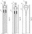
- Figures 2A-B depict embodiments where an outer catheter is disposed about the inner sheath 43.
- this is outer catheter 14A.
- this is outer catheter 14B.
- the outer catheter may be one with any sizing known in the art. As will be apparent with the figures, outer catheter 14A may make a tight fit with the gripper 36, while outer catheter 14B may not. Regardless of the precise size of the outer catheter, the inner sheath 43 may hold the gripper 36 in position.
- the outer catheter is a micro catheter.
- the microcatheter or outer catheter may have an inner diameter ranging from about 0.018 inches to about 0.035 inches.
- One skilled in the art will understand that the outer diameter of the microcatheter or outer catheter could be any size for the target site.
- outer catheter 14C may be oversized or too large to make a snug fit around the gripper 36.
- the gripper 36 may prematurely deploy the medical device 12, possibly deploying the medical device 12 before exiting the outer sheath 14C at the target delivery site. Such premature deployment may be unintended or undesired by the physician.
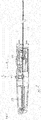
- FIG 3 depicts a more detailed view of the delivery apparatus of Figure 1 .
- the delivery apparatus may include an outer catheter (as in Fig. 2A ), and inner sheath 43, elongate member 22, a handle 80, a gripper 36, and connector piece 70.
- the inner sheath 43 may be slidably disposed in and coaxial with the outer catheter (e.g. Fig. 2A, 14A ).
- the inner sheath 43 may have a proximal end 16 extending distally to a distal end 18 and a lumen 20 formed therethrough, defining a longitudinal axis A.
- the inner sheath 43 may further include a marker band 78 at the distal end.
- the marker band 78 may be circumferentially disposed about the distal end 18 to allow the physician to visualize the distal end when disposed in the patient.
- the marker band 78 may be radiopaque, as known to those skilled in the art.
- marker band 78 may provide a stopping or resting point for the gripper 36 (as depicted in Fig. 3 ). In this way, the marker band 78 may be slidably disposed about a first member 38 and a second member 46 of gripper 36. This stopping point may facilitate the connected state by allowing the physician to pull the gripper 36 against the distal end 18.
- the marker band 78 may be disposed at the distal end 18 and may have a smaller or larger overall diameter than the rest of the inner sheath 43. This smaller or larger diameter, marker band diameter, may facilitate closing the gripper 36, allowing for wider engineering tolerances of the inner sheath 43.
- the marker band 78 does not provide a stopping point and the gripper 36 may be completely encircled or disposed inside the inner sheath 43 in the connected state.
- the elongate member 22 may be disposed in the lumen 20 coaxial with the inner sheath 43 along the longitudinal axis A.
- the elongate member 22 may have a first end 24 disposed adjacent the proximal end 16.
- the elongate member 22 may extend distally from the proximal end 16 to a second end 26 disposed adjacent the distal end 18.
- the elongate member 22 may be a wire.
- the elongate member 22 may be a seven strain cable wire.
- elongate member 22 may be a straight mandrel.
- Handle 80 may be connected to the proximal end 16 and the first end 24. One of the proximal end 16 and the first end 24 may be slidably received by the handle 80, giving two alternative embodiments to the delivery apparatus 10.
- the handle 80 may include an actuator 50 and a biasing member 35.
- the actuator 50 may be attached to the one of the first end 24 and the proximal end 16 (see e.g. Fig. 3 ).
- the actuator 50 may cooperate with the biasing member 35 such that actuating the actuator 50 moves the one of the first end 24 and the proximal end 16 relative to the longitudinal axis.
- Handle 80 may be activated to change the tension in the inner sheath 43 or the elongate member 22 through the biasing member 35.
- the biasing member 35 may be a spring.
- the biasing member 35 may be any member known in the art to change the tension of the inner sheath 43 or the elongate member 22.
- such alternative structure may be compressed gas or a balloon.
- the biasing member 35 may facilitate pulling the gripper 36 against the distal end 18, partly inside the inner sheath 43. It may also facilitate pulling the gripper 36 completely inside the inner sheath 43, both possibilities as discussed herein.
- the handle 80 may be rotated by the physician about the longitudinal axis during delivery or retrieval.
- the handle 80 may have two alternative embodiments.
- the actuator 50 may be attached to the first end 24 to move the first end relative to the longitudinal axis.
- the apparatus may be configured such that the actuator may move or push the elongate member distal relative to the longitudinal axis to uncover the gripper and release the medical device.
- the actuator 50 may be attached to the proximal end to move the proximal end relative to the longitudinal axis.
- the apparatus may be configured such that the actuator may move or pull the inner sheath proximal relative to the longitudinal axis to uncover the gripper and release the medical device.
- the handle 80 will be discussed in further detail with Figures 5-7 .
- the gripper 36 may include a first member 38 and a second member 46. Overall details of the apparatus are shown in Figure 3 , while specific details of the gripper 36 are illustrated in Figures 4A-B .
- the first member 38 may have a first segment 42 attached to the second end 26 and extend distally to a second segment 44.
- the second member 46 may be formed to cooperate with the first member 38 such that the first and second members opposing the face each other.
- the second member 46 may have a third segment 48 attached to the second end 26 and extending distally to a fourth segment 56.
- the first and third segments may be pivotably attached, defining a pivot area 62.
- the second and fourth segments may be detached.
- the first member 38 and a second member 46 may be any suitable shape to connect to the connector piece 70.
- the first member and a second member each include an arcuate portion, being arcuatly shaped.
- the pivot area 62 may be U-shaped. At the pivot area 62, the gripper may bend and accommodate stress stored in the bends as the gripper moves in and out of the inner sheath.
- the gripper 36 may be attached to the elongate member 22 in any method and means known in the art including gluing, soldering, welding.
- the gripper 36 may be any material known in the art to pivot, being resilient. Such examples include Nitinol, spring steel, stainless steel, and palladium.
- Nitinol is a metal alloy of nickel and titanium having a unique shape memory setting property and being biocompatible. At a transition temperature, Nitinol may undergo a phase change from Martensitic to Austenite, changing its structure. Here, the gripper 36 could be heat set or pre-set to the released state and maintained in the connected state (shown in Figures 4A-B ) until released or deployed. In addition to this phase changing ability, Nitinol is also quite flexible.
- the connector piece 70 may be removably attached to the medical device 12 and extend proximately from the device such that the first and second members cooperate to hold the connector piece 70 therebetween.
- the second and fourth segments may be disposed apart a distance (d1) apart, defining a connected state.
- the gripper 36 may be in the connected state when disposed partly in the inner sheath 43, disposed in contact with the connector piece 70.
- the first and second members being formed to biasingly pivot outwards at the pivot area 62, relative to the longitudinal axis.
- the second and fourth segments may be disposed apart a distance (d2) to release the connector piece 70.
- the distance (d2) may be greater than the distance (d1), defining a released state.
- the gripper 36 may be in the released state when disposed out farther of the inner sheath 43 relative to the connected state, being disposed out of contact with the connector piece 70.
- the apparatus thereby allows independent movement between the inner sheath 43 and the outer catheter for positioning the medical device 12.
- the connector piece 70 may further include a sphere 72, a neck 74, and a joint 76.
- the joint 76 allows rotational freedom between the sphere 72 and the medical device 12.
- the sphere 72 may be disposed proximal the neck 74 and being connected to the neck 74.
- the neck 74 may distally extend from the sphere 72 to the joint 76.
- the joint 76 may be connected to the medical device 12 to attach the connector piece 72 the device 12.
- the neck 74 may be rotational about the longitudinal axis at the joint 76 such that the neck 74 and the sphere 72 rotate together.
- the neck 74 and the sphere 72 rotate separate, or are rotationally independent, from the medical device 12.
- the independent rotational movement about the longitudinal axis between the connector piece 70 and the medical device 12 allows easier movement of the apparatus through certain body portions (e.g. tortuous vasculature). This may allow the physician to rotate or induce a torque to the connector piece 70 while alleviating any stress or strain on the medical device 12 during delivery or retrieval in the connected state.
- the gripper 36 being arcuate corresponds in shape to the sphere 72. This allows selective coupling between the gripper 36 and the connector piece 70, as shown in Figure 3 .
- the connector piece may be made of any material known in the art to satisfy the requirements of the connector piece.
- the connector piece may be platinum, palladium, or stainless steel.
- Figures 4A-B depicts two possible states of the apparatus: the connected state and the released state.
- the apparatus may be in the connected state where the sphere 70 is disposed in the gripper 36.
- the gripper may extend distally from the distal end 18 about 0 millimeters (mm) to about 1 millimeter. More preferably, the gripper may extend distally from the distal end 18 about 0.3 mm to about 0.5 mm in the connected state.
- Figure 4B depicts the released state where the sphere 70 is not connected to the gripper 36.
- the second segment 44 and the fourth segment 56 may extend distally about 1 millimeter to about 10 millimeters from the distal end 18, disposed apart the distance (d2). More preferably, the second segment 44 and the fourth segment 56 may extend distally about 2 mm to about 6 mm from the distal end 18 in the released state.
- Figures 5 and 6A-B depict further details of the handle, as discussed herein.
- Figure 5 illustrates details of the handle 80
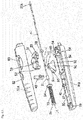
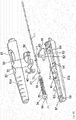
- Figures 6A-B illustrate exploded forms to further display the internal components thereof. It will be appreciated, however, that the handle unit can be used for the deployment and retrieval in a wide variety of locations of a patient.
- the handle 80 contacts inner sheath 43.
- the inner sheath may have sufficiently flexibility to provide the required trackability.
- actuator 50 is a first button.
- Such force F1 may compress or elongate the biasing member 35, shown as a spring in Figure 5 .
- the actuator 50 may act by way of a force substantially perpendicular to the longitudinal axis, either in connection with the force F1 or without a need for the force F1.
- the device may comprise a locking member 40 (details of which will be discussed with Figures 6-7 ).
- the locking member 40 may have a locked state and an unlocked state.
- the locking member may include a trigger, at least one engagement element, and a receiver element located on the one of the inner sheath and the elongate member.
- the trigger may be a second button and may be moveable in a direction toward and substantially perpendicular to the longitudinal axis to lock the one of the inner sheath and the elongate member relative to the other of the inner sheath and the elongate member by engaging the at least one engagement element with the receiver element.
- the trigger may also be moveable to unlock the apparatus.
- a force F2 on the trigger may move the locking member 40 between the locked and unlocked states, depicted by the arrow in Figure 5 .
- Figure 6A depicts one embodiment of the handle, where the elongate member 22 is slidably received in the handle.
- the handle is formed of an elongate casing formed in two halves 81A, 81 B which engage along its length.
- the top half 81A is provided with two holes 82, 83 which allow access to an actuator or first button 50 and a locking member 40, both described in further detail below.
- the handle also houses the proximal end of the inner sheath 43, within which is mounted the flexible elongate member 22.
- An annular holding disc 38 is fixed to the inner sheath 43 and serves to fix the inner sheath 43 to the handle 80 in the longitudinal direction of the apparatus.
- the elongate member 22 is provided with a spring 35 over its proximal end, between two annular shoulder or stop discs 34, 36.
- the stop disc 36 is fixed to the proximal end of the elongate member 22, while the stop disc 34 is slidable on the elongate member 22.
- the interior of the handle 80 is provided with first and second walls 37, 39, delimiting the ends of a spring chamber 85 in the handle 80.
- the two stop members 34, 36 abut against the walls 37, 39.
- the distal wall 37 is provided with a slot or other aperture 41 therein allowing passage of the elongate member 22.
- the apparatus is also provided with a receiver or engagement element 31, described in full detail below, for use in locking the apparatus.
- a follower element 102 fixed to the elongate member 22.
- the follower element 102 is designed so as to fit within a recess 60 of a carriage element 90.
- the carriage element 90 has, in this embodiment, a substantially flat lower surface 92 which is able to slide along a track 84 within the handle, such sliding movement causing, by virtue of the coupling of the handle element 90 to the follower element 102, the inner sheath 43 to slide with the carriage 90.
- the first button 50 of the handle is provided with a hinge 51 having two opposing pins 53 upstanding therefrom, able to engage a suitable recess (not shown) in the top portion of the handle and to rest upon supports 54 in the lower portion of the handle 80.
- the first button 50 is also provided with a depending follower portion 52 which cooperates with a bevelled or sloping surface 91 of the carriage element 90.
- the design is such that upon pressure being applied to depress the button 50, this pivots about the hinge 51, causing the depending follower member 52 to rotate, to abut and then to slide along the sloping surface 91 of the carriage 90. As this occurs, the carriage 90 is moved in a distal direction, which is to the right in the view of Figure 6A .
- the proximal wall of the carriage unit 90 at the bottom end of the sloping surface 91, is provided with a recessed zone 93, in this embodiment in the form of a channel extending traverse to the direction of movement of the carriage.
- a recessed zone 93 in this embodiment in the form of a channel extending traverse to the direction of movement of the carriage.
- Figure 6A also shows the locking member 40, which cooperates with the engagement element 31.
- locking member 40 may be spaced apart from actuator 50 along the handle. Specific details of the locking member 40 are described in further detail below in connection with Figures 7A-B .
- the dependent element 52 slides down the sloping wall 91 and in so doing pushes the carriage 90 forwards, in a distal direction.
- the movement of the carriage 90 by virtue of the connection through the element 102, pushes the elongate member 22 forward.
- a medical device is gripped onto the end of the elongate member 22, this is in turn disposed out of the inner sheath, eventually allowing for release of the medical device carried by the apparatus.
- the coil spring 35 resiliently extends or elongates.
- the coil spring 35 can return to its original position, thereby pulling the follower 90 backwards, which in turn pulls backwards the elongate member 22, thereby retracting this. Such retraction is affected both for withdrawing the apparatus after deployment of the medical device into a patient and also to pull into the apparatus the medical device, which is to be retrieved from a patient.
- the coil spring 35 is preferably of sufficient strength to be able to pull back and collapse a medical device by the force of the spring alone.
- Figure 6B show another version of a handle having similar characteristics as the handle of Figure 6A .
- the mechanism could be said to be reversed compared to the embodiment of 6A in that it operates to pull back the inner sheath 43, rather than to push forwards the elongate member 22.
- the carriage element 90 is reversed compared to the embodiment of 6A, as is the button 50, such that the carriage moves backwardly in a proximal direction upon depression and/or proximal retraction of the button 50.
- the inner sheath 43 also extends to the proximal portion of the handle and is provided thereon with the engaging element 31 and with the spring retaining disc 49, which is fixed to the inner sheath 43.
- Another retaining disc or ring 36 is fixed to the proximal end of the inner sheath 43 and a sliding disc 34 is located between the two fixed discs 36 and 43.
- the disc 36 at the end of the handle fits within a chamber 85 at the end of the handle 80 so as to fix the elongate member 22 to the handle 80 such that the elongate member 22 cannot move longitudinally relative to the handle. It is the inner sheath 43 which moves relative to the handle 80.
- the dependent portion 52 of the first button 50 slides down the sloping surface 91 of the carriage member 90, pushing the carriage member backwards in a proximal direction, thereby pulling the inner sheath 43 in a proximal direction so as to expose the second end of the elongate member 22.
- a device held by the elongate member 22 can then be released or, in the case of a retrieval operation, cause the gripper (not shown here) to grab on to an implanted device so as to effect its retrieval from within the patient.
- the spring 35 will cause that device, if of collapsible form, to be collapsed into the inner sheath 43 or an enveloping outer sheath, so as to capture the device within the apparatus for withdrawal from the patient.
- Figures 7A-B show examples of a preferred embodiment of locking member 40. It is preferred that both the elongate member and inner sheath are kept locked longitudinally with respect to the handle 80 until the point that a physician desires to release or withdraw the medical device into or from a patient. In particular, it is preferred that the inner sheath and elongate member are not movable relative to one another from the point of assembly of the apparatus to the point at which it is to be used clinically, thus to be locked in particular during transportation and handling of the apparatus. The locking member provides such function.
- the locking member 40 includes a trigger or second button 141, which is accessible from the aperture 82 in the handle.
- the second button 141 includes first and second prong elements 142, 143 depending from the trigger or second button 141, which in this embodiment are substantially parallel to one another.
- the prongs 142, 143 are provided with internal surfaces having, in this embodiment, a plurality of vertically extending teeth 144, elongate teeth which extend in a direction substantially parallel to the direction of movement of the second button 141.
- the engagement portion 31 provided on the elongate member 22 or inner sheath 43, in the examples of Figures 6A-B , is in the form of a grooved annular bushing, the grooves 33 of which are sized and spaced to receive respective teeth 144 of the second button 141.
- the second button 141 is provided with an enlarged rounded aperture 145 above the pronged elements 142, 143 and in particular above the teeth 144.
- the enlarged aperture 145 is larger than the maximum diameter of the engagement element 31, such that when the button 141 is depressed to such an extent that the engagement portion 31 becomes located within the enlarged aperture 145, the engagement portion 31 can slide within the aperture 145, thus allowing for sliding of the elongate member 22 or inner sheath 43.
- the button 141 is also provided with shoulders 150, 152 which abut suitable surfaces in the top half of the handle 80 so as to limit the upward movement of the button 141 within the handle.
- the lower surfaces of the prongs 142, 144 are, in this embodiment, substantially flat and, in practice, support one or more elements (not shown) intended to bias the button upwardly. These elements thus retain the button normally in an upward-most position.
- the arrangement is such that when the second button 141 is in its uppermost position, the teeth 144 engage the grooves 33 or surface of the engagement element 31, so as to lock the elongate member 22 relative to the inner sheath 43.
- the button 141 must be depressed, so as to locate the engagement portion 31 in the enlarged aperture 145, before the elongate member can be moved relative to the inner sheath or vice versa.
- a physician must first depress the locking member 40 to unlock the apparatus and only then will the depression of the first button 50 cause movement so as to deploy the medical device.
- the arrangement has another advantage, namely that the arrangement of locking member 40 and engagement element 31 are not dependent upon a particular longitudinal alignment of these two components.
- This allows not only for manufacturing tolerances but also the use of different sizes of devices to be deployed/retrieved. It allows the device to be locked in one of a plurality of relative positions of the inner sheath and elongate member. For example, this can allow the physician to lock the elongate member 22 in its most extended position, for example, to assist in the retrieval of the medical device.
- simple depression of the locking member 40 will cause the handle 80 to come into action. It is preferred in some embodiments that this action is swift, which can facilitate in the collapse of the device being retrieved.
- Figure 8 depict details of the steps of one delivery method for a medical device.
- the physician may coupling the medical device to a delivery apparatus, structural details of both discussed herein.
- the physician may slidably moving the inner sheath and the elongate member relative to the outer catheter to position the device within the body vessel.
- the physician may move one of the second end and the distal end relative to each other such that the gripper opens, the apparatus allowing independent movement between the inner sheath and the outer catheter for positioning the medical device.
- the physician Due in part to the independent nature of the inner sheath from the outer catheter, the physician has the ability to release the connector piece from the gripper and, subsequently, recouple the connector piece to the gripper. As such, the physician may recouple the device to the apparatus after the step of moving one of the second end and the distal end. The physician can also release the connector piece in the patient's body, and, subsequently, recouple the device to the apparatus to abort the procedure entirely (i.e. withdrawing the medical device from the body).
- the apparatus may be initially unlocked with the locking device in an unlocked position.
- One method of use may involve locking the locking member before the step of coupling.
- the physician may unlock the locking member before the step of moving the gripper.
- a method for delivering a medical device to a body vessel comprising: coupling the medical device to a delivery apparatus, the apparatus comprising: an outer catheter; an inner sheath being slidably disposed in and coaxial with the outer catheter, the inner sheath having a proximal end and extending distally to a distal end with a lumen formed therethrough, defining a longitudinal axis; an elongate member being disposed in the lumen and coaxial with the inner sheath, the elongate member having a first end disposed adjacent the proximal end and extending distally from the proximal end to a second end disposed adjacent the distal end; a handle being connected to the proximal end and the first end, one of the proximal end and the first end being slidably received by the handle, the handle comprising an actuator and a biasing member, the actuator being attached to the one of the first end and the proximal end and cooperating with the bias
Landscapes
- Health & Medical Sciences (AREA)
- Surgery (AREA)
- Life Sciences & Earth Sciences (AREA)
- Heart & Thoracic Surgery (AREA)
- Molecular Biology (AREA)
- Vascular Medicine (AREA)
- Engineering & Computer Science (AREA)
- Biomedical Technology (AREA)
- Reproductive Health (AREA)
- Medical Informatics (AREA)
- Nuclear Medicine, Radiotherapy & Molecular Imaging (AREA)
- Animal Behavior & Ethology (AREA)
- General Health & Medical Sciences (AREA)
- Public Health (AREA)
- Veterinary Medicine (AREA)
- Neurosurgery (AREA)
- Surgical Instruments (AREA)
Applications Claiming Priority (2)
| Application Number | Priority Date | Filing Date | Title |
|---|---|---|---|
| US201562147935P | 2015-04-15 | 2015-04-15 | |
| US15/079,351 US20160302794A1 (en) | 2015-04-15 | 2016-03-24 | Detachment mechanism for vascular devices |
Publications (2)
| Publication Number | Publication Date |
|---|---|
| EP3081173A2 true EP3081173A2 (fr) | 2016-10-19 |
| EP3081173A3 EP3081173A3 (fr) | 2016-12-21 |
Family
ID=55745630
Family Applications (1)
| Application Number | Title | Priority Date | Filing Date |
|---|---|---|---|
| EP16164753.2A Withdrawn EP3081173A3 (fr) | 2015-04-15 | 2016-04-11 | Mécanisme de détachement pour dispositifs vasculaires |
Country Status (2)
| Country | Link |
|---|---|
| US (1) | US20160302794A1 (fr) |
| EP (1) | EP3081173A3 (fr) |
Families Citing this family (9)
| Publication number | Priority date | Publication date | Assignee | Title |
|---|---|---|---|---|
| GB201318403D0 (en) * | 2013-10-17 | 2013-12-04 | Cook Medical Technologies Llc | Release mechanism |
| CN108095804B (zh) * | 2018-02-10 | 2023-08-08 | 郑州大学第一附属医院 | 一种脑血管可转变性多功能内支架装载回收与释放装置 |
| CN116940311A (zh) | 2022-02-23 | 2023-10-24 | 艾露姆技术股份有限公司 | 神经血管分流器和递送系统 |
| WO2023159521A1 (fr) * | 2022-02-25 | 2023-08-31 | Micro-Tech (Nanjing) Co., Ltd. | Dispositif médical pour provoquer l'hémostase d'un vaisseau sanguin |
| US20250017596A1 (en) * | 2022-02-25 | 2025-01-16 | Micro-Tech (Nanjing) Co., Ltd. | Medical Device for Causing Hemostasis of Blood Vessel |
| US20250221714A1 (en) * | 2022-03-28 | 2025-07-10 | Clearstream Technologies Limited | Delivery Systems for Implants |
| US12471926B2 (en) | 2023-02-22 | 2025-11-18 | eLum Technologies, Inc. | Systems and methods for customizable flow diverter implants |
| US12213676B2 (en) | 2023-02-22 | 2025-02-04 | eLum Technologies, Inc. | Systems and methods for customizable flow diverter implants |
| US12502177B2 (en) | 2023-02-22 | 2025-12-23 | eLum Technologies, Inc. | Systems and methods for customizable flow diverter implants |
Family Cites Families (12)
| Publication number | Priority date | Publication date | Assignee | Title |
|---|---|---|---|---|
| US5217484A (en) * | 1991-06-07 | 1993-06-08 | Marks Michael P | Retractable-wire catheter device and method |
| US5350397A (en) * | 1992-11-13 | 1994-09-27 | Target Therapeutics, Inc. | Axially detachable embolic coil assembly |
| US6296622B1 (en) * | 1998-12-21 | 2001-10-02 | Micrus Corporation | Endoluminal device delivery system using axially recovering shape memory material |
| JP4465192B2 (ja) * | 2002-03-15 | 2010-05-19 | エヌエムティー メディカル, インコーポレイティッド | 移植物の配置において有用な結合システム |
| US20070186933A1 (en) * | 2006-01-17 | 2007-08-16 | Pulmonx | Systems and methods for delivering flow restrictive element to airway in lungs |
| US7942894B2 (en) * | 2006-01-31 | 2011-05-17 | Codman & Shurtleff, Inc. | Embolic device delivery system |
| US7553321B2 (en) * | 2006-03-31 | 2009-06-30 | Cordis Development Corporation | Chemically based vascular occlusion device deployment |
| US20070299461A1 (en) * | 2006-06-21 | 2007-12-27 | Boston Scientific Scimed, Inc. | Embolic coils and related components, systems, and methods |
| US8845710B2 (en) * | 2007-11-30 | 2014-09-30 | Cook Medical Technologies Llc | Method and apparatus for introducing intraluminal prostheses |
| CN102438533B (zh) * | 2009-04-20 | 2014-11-26 | 加奇生物科技(上海)有限公司 | 一种用于输送栓塞器械的机械互锁连接输送装置 |
| GB2509952B (en) * | 2013-01-18 | 2015-01-28 | Cook Medical Technologies Llc | Medical device loading and carrier tool |
| GB2533087B (en) * | 2014-12-08 | 2018-08-08 | Cook Medical Technologies Llc | Medical implant detachment mechanism and introducer assembly |
-
2016
- 2016-03-24 US US15/079,351 patent/US20160302794A1/en not_active Abandoned
- 2016-04-11 EP EP16164753.2A patent/EP3081173A3/fr not_active Withdrawn
Non-Patent Citations (1)
| Title |
|---|
| None |
Also Published As
| Publication number | Publication date |
|---|---|
| US20160302794A1 (en) | 2016-10-20 |
| EP3081173A3 (fr) | 2016-12-21 |
Similar Documents
| Publication | Publication Date | Title |
|---|---|---|
| EP3081173A2 (fr) | Mécanisme de détachement pour dispositifs vasculaires | |
| CN101448464B (zh) | 用于以机械方式定位血管内植入物的系统和方法 | |
| US9375333B1 (en) | Implantable device detachment systems and associated devices and methods | |
| US6936058B2 (en) | Over-the-wire interlock attachment/detachment mechanism | |
| CN103251436B (zh) | 用于机械定位脉管内植入物的系统和方法 | |
| EP2862523B1 (fr) | Mécanisme de libération | |
| EP2217181B1 (fr) | Appareil permettant l'introduction de prothèses intraluminales | |
| EP2777645B1 (fr) | Poignée de fermeture rapide pour dispositifs médicaux | |
| US10159489B2 (en) | Systems and methods for delivering multiple embolization coils | |
| CN110859692A (zh) | 植入物输送系统 | |
| CN108348258A (zh) | 用于将植入物输送到血管病症部位的装置和方法 | |
| CN109199660B (zh) | 一种医用输送装置及其输送系统 | |
| EP4129245A1 (fr) | Dispositifs, systèmes et procédés de distribution de dispositif médical |
Legal Events
| Date | Code | Title | Description |
|---|---|---|---|
| PUAI | Public reference made under article 153(3) epc to a published international application that has entered the european phase |
Free format text: ORIGINAL CODE: 0009012 |
|
| AK | Designated contracting states |
Kind code of ref document: A2 Designated state(s): AL AT BE BG CH CY CZ DE DK EE ES FI FR GB GR HR HU IE IS IT LI LT LU LV MC MK MT NL NO PL PT RO RS SE SI SK SM TR |
|
| AX | Request for extension of the european patent |
Extension state: BA ME |
|
| PUAL | Search report despatched |
Free format text: ORIGINAL CODE: 0009013 |
|
| AK | Designated contracting states |
Kind code of ref document: A3 Designated state(s): AL AT BE BG CH CY CZ DE DK EE ES FI FR GB GR HR HU IE IS IT LI LT LU LV MC MK MT NL NO PL PT RO RS SE SI SK SM TR |
|
| AX | Request for extension of the european patent |
Extension state: BA ME |
|
| RIC1 | Information provided on ipc code assigned before grant |
Ipc: A61B 17/12 20060101AFI20161115BHEP Ipc: A61B 17/00 20060101ALN20161115BHEP |
|
| STAA | Information on the status of an ep patent application or granted ep patent |
Free format text: STATUS: THE APPLICATION HAS BEEN PUBLISHED |
|
| STAA | Information on the status of an ep patent application or granted ep patent |
Free format text: STATUS: THE APPLICATION IS DEEMED TO BE WITHDRAWN |
|
| 18D | Application deemed to be withdrawn |
Effective date: 20170622 |