EP3081192A1 - Lentille intraoculaire réglable - Google Patents
Lentille intraoculaire réglable Download PDFInfo
- Publication number
- EP3081192A1 EP3081192A1 EP14869790.7A EP14869790A EP3081192A1 EP 3081192 A1 EP3081192 A1 EP 3081192A1 EP 14869790 A EP14869790 A EP 14869790A EP 3081192 A1 EP3081192 A1 EP 3081192A1
- Authority
- EP
- European Patent Office
- Prior art keywords
- supporting portion
- optical
- lens
- capsule
- ring member
- Prior art date
- Legal status (The legal status is an assumption and is not a legal conclusion. Google has not performed a legal analysis and makes no representation as to the accuracy of the status listed.)
- Withdrawn
Links
- 230000003287 optical effect Effects 0.000 claims abstract description 181
- 239000002775 capsule Substances 0.000 claims abstract description 134
- 238000001356 surgical procedure Methods 0.000 claims description 43
- 239000000126 substance Substances 0.000 claims description 22
- 230000009969 flowable effect Effects 0.000 claims description 20
- 208000024891 symptom Diseases 0.000 claims description 14
- 230000004308 accommodation Effects 0.000 description 41
- 230000007423 decrease Effects 0.000 description 20
- 210000004240 ciliary body Anatomy 0.000 description 18
- ATJFFYVFTNAWJD-UHFFFAOYSA-N Tin Chemical compound [Sn] ATJFFYVFTNAWJD-UHFFFAOYSA-N 0.000 description 15
- 229910052718 tin Inorganic materials 0.000 description 15
- 208000002177 Cataract Diseases 0.000 description 13
- 230000001886 ciliary effect Effects 0.000 description 13
- 210000003205 muscle Anatomy 0.000 description 13
- 230000008602 contraction Effects 0.000 description 11
- 230000004438 eyesight Effects 0.000 description 8
- 210000000887 face Anatomy 0.000 description 6
- 208000001491 myopia Diseases 0.000 description 6
- 208000008516 Capsule Opacification Diseases 0.000 description 5
- 238000000034 method Methods 0.000 description 4
- 239000013013 elastic material Substances 0.000 description 3
- 201000010041 presbyopia Diseases 0.000 description 3
- 239000013589 supplement Substances 0.000 description 3
- XUIMIQQOPSSXEZ-UHFFFAOYSA-N Silicon Chemical compound [Si] XUIMIQQOPSSXEZ-UHFFFAOYSA-N 0.000 description 2
- -1 acryl Chemical group 0.000 description 2
- 201000010099 disease Diseases 0.000 description 2
- 208000037265 diseases, disorders, signs and symptoms Diseases 0.000 description 2
- 230000000694 effects Effects 0.000 description 2
- 210000001339 epidermal cell Anatomy 0.000 description 2
- 238000000605 extraction Methods 0.000 description 2
- 210000001542 lens epithelial cell Anatomy 0.000 description 2
- 239000000463 material Substances 0.000 description 2
- 229920003229 poly(methyl methacrylate) Polymers 0.000 description 2
- 239000004926 polymethyl methacrylate Substances 0.000 description 2
- 229910052710 silicon Inorganic materials 0.000 description 2
- 239000010703 silicon Substances 0.000 description 2
- 229920002818 (Hydroxyethyl)methacrylate Polymers 0.000 description 1
- WOBHKFSMXKNTIM-UHFFFAOYSA-N Hydroxyethyl methacrylate Chemical compound CC(=C)C(=O)OCCO WOBHKFSMXKNTIM-UHFFFAOYSA-N 0.000 description 1
- 230000032683 aging Effects 0.000 description 1
- 238000005452 bending Methods 0.000 description 1
- 239000000835 fiber Substances 0.000 description 1
- 230000004313 glare Effects 0.000 description 1
- 125000001475 halogen functional group Chemical group 0.000 description 1
- 239000000017 hydrogel Substances 0.000 description 1
- 230000002209 hydrophobic effect Effects 0.000 description 1
- 238000012986 modification Methods 0.000 description 1
- 230000004048 modification Effects 0.000 description 1
- 230000002093 peripheral effect Effects 0.000 description 1
- 229920000058 polyacrylate Polymers 0.000 description 1
- 229920000642 polymer Polymers 0.000 description 1
- 239000011347 resin Substances 0.000 description 1
- 229920005989 resin Polymers 0.000 description 1
- 230000035945 sensitivity Effects 0.000 description 1
- 229920003002 synthetic resin Polymers 0.000 description 1
- 239000000057 synthetic resin Substances 0.000 description 1
- 230000000007 visual effect Effects 0.000 description 1
Images



Classifications
-
- A—HUMAN NECESSITIES
- A61—MEDICAL OR VETERINARY SCIENCE; HYGIENE
- A61F—FILTERS IMPLANTABLE INTO BLOOD VESSELS; PROSTHESES; DEVICES PROVIDING PATENCY TO, OR PREVENTING COLLAPSING OF, TUBULAR STRUCTURES OF THE BODY, e.g. STENTS; ORTHOPAEDIC, NURSING OR CONTRACEPTIVE DEVICES; FOMENTATION; TREATMENT OR PROTECTION OF EYES OR EARS; BANDAGES, DRESSINGS OR ABSORBENT PADS; FIRST-AID KITS
- A61F2/00—Filters implantable into blood vessels; Prostheses, i.e. artificial substitutes or replacements for parts of the body; Appliances for connecting them with the body; Devices providing patency to, or preventing collapsing of, tubular structures of the body, e.g. stents
- A61F2/02—Prostheses implantable into the body
- A61F2/14—Eye parts, e.g. lenses or corneal implants; Artificial eyes
- A61F2/16—Intraocular lenses
- A61F2/1613—Intraocular lenses having special lens configurations, e.g. multipart lenses; having particular optical properties, e.g. pseudo-accommodative lenses, lenses having aberration corrections, diffractive lenses, lenses for variably absorbing electromagnetic radiation, lenses having variable focus
- A61F2/1624—Intraocular lenses having special lens configurations, e.g. multipart lenses; having particular optical properties, e.g. pseudo-accommodative lenses, lenses having aberration corrections, diffractive lenses, lenses for variably absorbing electromagnetic radiation, lenses having variable focus having adjustable focus; power activated variable focus means, e.g. mechanically or electrically by the ciliary muscle or from the outside
- A61F2/1635—Intraocular lenses having special lens configurations, e.g. multipart lenses; having particular optical properties, e.g. pseudo-accommodative lenses, lenses having aberration corrections, diffractive lenses, lenses for variably absorbing electromagnetic radiation, lenses having variable focus having adjustable focus; power activated variable focus means, e.g. mechanically or electrically by the ciliary muscle or from the outside for changing shape
-
- A—HUMAN NECESSITIES
- A61—MEDICAL OR VETERINARY SCIENCE; HYGIENE
- A61F—FILTERS IMPLANTABLE INTO BLOOD VESSELS; PROSTHESES; DEVICES PROVIDING PATENCY TO, OR PREVENTING COLLAPSING OF, TUBULAR STRUCTURES OF THE BODY, e.g. STENTS; ORTHOPAEDIC, NURSING OR CONTRACEPTIVE DEVICES; FOMENTATION; TREATMENT OR PROTECTION OF EYES OR EARS; BANDAGES, DRESSINGS OR ABSORBENT PADS; FIRST-AID KITS
- A61F2/00—Filters implantable into blood vessels; Prostheses, i.e. artificial substitutes or replacements for parts of the body; Appliances for connecting them with the body; Devices providing patency to, or preventing collapsing of, tubular structures of the body, e.g. stents
- A61F2/02—Prostheses implantable into the body
- A61F2/14—Eye parts, e.g. lenses or corneal implants; Artificial eyes
- A61F2/16—Intraocular lenses
- A61F2/16015—Lens having spacers for providing a gap between the posterior capsule and a posterior surface of the intraocular lens
-
- A—HUMAN NECESSITIES
- A61—MEDICAL OR VETERINARY SCIENCE; HYGIENE
- A61F—FILTERS IMPLANTABLE INTO BLOOD VESSELS; PROSTHESES; DEVICES PROVIDING PATENCY TO, OR PREVENTING COLLAPSING OF, TUBULAR STRUCTURES OF THE BODY, e.g. STENTS; ORTHOPAEDIC, NURSING OR CONTRACEPTIVE DEVICES; FOMENTATION; TREATMENT OR PROTECTION OF EYES OR EARS; BANDAGES, DRESSINGS OR ABSORBENT PADS; FIRST-AID KITS
- A61F2/00—Filters implantable into blood vessels; Prostheses, i.e. artificial substitutes or replacements for parts of the body; Appliances for connecting them with the body; Devices providing patency to, or preventing collapsing of, tubular structures of the body, e.g. stents
- A61F2/02—Prostheses implantable into the body
- A61F2/14—Eye parts, e.g. lenses or corneal implants; Artificial eyes
- A61F2/16—Intraocular lenses
- A61F2/1613—Intraocular lenses having special lens configurations, e.g. multipart lenses; having particular optical properties, e.g. pseudo-accommodative lenses, lenses having aberration corrections, diffractive lenses, lenses for variably absorbing electromagnetic radiation, lenses having variable focus
- A61F2/1648—Multipart lenses
-
- A—HUMAN NECESSITIES
- A61—MEDICAL OR VETERINARY SCIENCE; HYGIENE
- A61F—FILTERS IMPLANTABLE INTO BLOOD VESSELS; PROSTHESES; DEVICES PROVIDING PATENCY TO, OR PREVENTING COLLAPSING OF, TUBULAR STRUCTURES OF THE BODY, e.g. STENTS; ORTHOPAEDIC, NURSING OR CONTRACEPTIVE DEVICES; FOMENTATION; TREATMENT OR PROTECTION OF EYES OR EARS; BANDAGES, DRESSINGS OR ABSORBENT PADS; FIRST-AID KITS
- A61F2/00—Filters implantable into blood vessels; Prostheses, i.e. artificial substitutes or replacements for parts of the body; Appliances for connecting them with the body; Devices providing patency to, or preventing collapsing of, tubular structures of the body, e.g. stents
- A61F2/02—Prostheses implantable into the body
- A61F2/14—Eye parts, e.g. lenses or corneal implants; Artificial eyes
- A61F2/16—Intraocular lenses
- A61F2/1694—Capsular bag spreaders therefor
-
- A—HUMAN NECESSITIES
- A61—MEDICAL OR VETERINARY SCIENCE; HYGIENE
- A61F—FILTERS IMPLANTABLE INTO BLOOD VESSELS; PROSTHESES; DEVICES PROVIDING PATENCY TO, OR PREVENTING COLLAPSING OF, TUBULAR STRUCTURES OF THE BODY, e.g. STENTS; ORTHOPAEDIC, NURSING OR CONTRACEPTIVE DEVICES; FOMENTATION; TREATMENT OR PROTECTION OF EYES OR EARS; BANDAGES, DRESSINGS OR ABSORBENT PADS; FIRST-AID KITS
- A61F2/00—Filters implantable into blood vessels; Prostheses, i.e. artificial substitutes or replacements for parts of the body; Appliances for connecting them with the body; Devices providing patency to, or preventing collapsing of, tubular structures of the body, e.g. stents
- A61F2/02—Prostheses implantable into the body
- A61F2/14—Eye parts, e.g. lenses or corneal implants; Artificial eyes
- A61F2/16—Intraocular lenses
- A61F2/1613—Intraocular lenses having special lens configurations, e.g. multipart lenses; having particular optical properties, e.g. pseudo-accommodative lenses, lenses having aberration corrections, diffractive lenses, lenses for variably absorbing electromagnetic radiation, lenses having variable focus
- A61F2/1624—Intraocular lenses having special lens configurations, e.g. multipart lenses; having particular optical properties, e.g. pseudo-accommodative lenses, lenses having aberration corrections, diffractive lenses, lenses for variably absorbing electromagnetic radiation, lenses having variable focus having adjustable focus; power activated variable focus means, e.g. mechanically or electrically by the ciliary muscle or from the outside
- A61F2/1627—Intraocular lenses having special lens configurations, e.g. multipart lenses; having particular optical properties, e.g. pseudo-accommodative lenses, lenses having aberration corrections, diffractive lenses, lenses for variably absorbing electromagnetic radiation, lenses having variable focus having adjustable focus; power activated variable focus means, e.g. mechanically or electrically by the ciliary muscle or from the outside for changing index of refraction, e.g. by external means or by tilting
-
- A—HUMAN NECESSITIES
- A61—MEDICAL OR VETERINARY SCIENCE; HYGIENE
- A61F—FILTERS IMPLANTABLE INTO BLOOD VESSELS; PROSTHESES; DEVICES PROVIDING PATENCY TO, OR PREVENTING COLLAPSING OF, TUBULAR STRUCTURES OF THE BODY, e.g. STENTS; ORTHOPAEDIC, NURSING OR CONTRACEPTIVE DEVICES; FOMENTATION; TREATMENT OR PROTECTION OF EYES OR EARS; BANDAGES, DRESSINGS OR ABSORBENT PADS; FIRST-AID KITS
- A61F2/00—Filters implantable into blood vessels; Prostheses, i.e. artificial substitutes or replacements for parts of the body; Appliances for connecting them with the body; Devices providing patency to, or preventing collapsing of, tubular structures of the body, e.g. stents
- A61F2/02—Prostheses implantable into the body
- A61F2/14—Eye parts, e.g. lenses or corneal implants; Artificial eyes
- A61F2/16—Intraocular lenses
- A61F2002/1681—Intraocular lenses having supporting structure for lens, e.g. haptics
- A61F2002/1682—Intraocular lenses having supporting structure for lens, e.g. haptics having mechanical force transfer mechanism to the lens, e.g. for accommodating lenses
-
- A—HUMAN NECESSITIES
- A61—MEDICAL OR VETERINARY SCIENCE; HYGIENE
- A61F—FILTERS IMPLANTABLE INTO BLOOD VESSELS; PROSTHESES; DEVICES PROVIDING PATENCY TO, OR PREVENTING COLLAPSING OF, TUBULAR STRUCTURES OF THE BODY, e.g. STENTS; ORTHOPAEDIC, NURSING OR CONTRACEPTIVE DEVICES; FOMENTATION; TREATMENT OR PROTECTION OF EYES OR EARS; BANDAGES, DRESSINGS OR ABSORBENT PADS; FIRST-AID KITS
- A61F2250/00—Special features of prostheses classified in groups A61F2/00 - A61F2/26 or A61F2/82 or A61F9/00 or A61F11/00 or subgroups thereof
- A61F2250/0003—Special features of prostheses classified in groups A61F2/00 - A61F2/26 or A61F2/82 or A61F9/00 or A61F11/00 or subgroups thereof having an inflatable pocket filled with fluid, e.g. liquid or gas
Definitions
- the present invention relates to an accommodating intraocular lens which is inserted into a lens capsule of which the anterior capsule is incised during ophthalmic surgeries such as an extracapsular extraction surgery performed as a part of a cataract surgery, a refractive correction surgery, or a presbyopia correction surgery.
- a lens L is a convex transparent member having a diameter of approximately 9 to 10 mm and a thickness of approximately 4 to 5 mm and exerting a lens function, and is fixed to a ciliary body C by Zinn's zonules Z in such a manner as to be arranged on the rear side of the iris I in a state of being encapsulated by a lens capsule S.
- the thickness of the lens is changed according to contraction and relaxation of the ciliary muscles of the ciliary bodies to refract light entering the eyes, whereby the focus accommodation is realized.
- this accommodation mechanism it is known that the contraction and relaxation functions of the ciliary muscles of the ciliary bodies are maintained satisfactorily in old ages in the same manner as in young ages.
- accommodation power the ability to accommodate the focus range freely from distance vision to near vision is lost (this is referred to as presbyopia).
- a disease called a cataract which is a clouding of the lens mainly resulting from aging is one of the diseases occurring in the lens, and many patients have cataract surgery to treat their cataracts.
- This surgery generally uses a method in which the anterior capsule is incised in a circular form to create a circular hole, the contents of the cloudy lens are extracted from the hole according to phacoemulsification, and an intraocular lens is inserted into a transparent lens capsule while leaving only the lens capsule with the circular hole formed therein.
- the cataract surgery based on this method has been currently applied to more than one million patients in Japan every year and more than 3 million patients in the United States of America every year, and the intraocular lenses used for this surgery are generally monofocal lenses.
- the monofocal lenses are generally formed of a material such as polymethylmethacrylate (PMMA), silicon, or acryl, and it is not possible to change the thickness of the monofocal lens itself, the loss of the accommodation power after the surgery is unavoidable.
- multifocal lenses which are arranged in a refractive multifocal lens having portions having different refractive powers formed concentrically in an optical portion and a diffractive multifocal lens having a structure causing an optical diffract ion phenomenon formed in an optical portion so as to disperse and capture light entering into the eyes are arranged as multifocal lenses for distance vision and near vision (in some cases, for intermediate vision).
- an accommodating intraocular lens including an optical portion formed of a convex lens and two joint-type connection arms arranged in such a manner as to come into contact with the inner side of a lens equator so that accommodation is realized by the optical portion moving back and forth is known (see Patent Document 1 below).
- the connection arm is attached to the optical portion at a first position on the connection arm and works harmoniously with the movement of the equator of the lens capsule to which the contraction and relaxation of the ciliary muscles of the ciliary bodies are transmitted via the Zinn's zonules at a second position on the connection arm.
- ring-shaped lens capsule expanding devices which are used for expanding the lens capsule before inserting an intraocular lens during cataract surgery have been proposed.
- These ring-shaped lens capsule expanding devices come in two types depending on the purpose.
- a capsular tension ring (a lens capsule expansion ring) which is an open ring formed in a C-shape. This ring is inserted from the inner side into the lens equators in which the Zinn's zonules are weak and ruptured to expand the lens equators outward to create a round shape.
- the other example is called an equator ring which is formed in an O-shape.
- This ring is a relatively thick closed ring (continuous ring) of which the cross-section has sharp edges such as a square.
- This ring is arranged on an inner side of the lens equators to form a strong bent portion in the lens capsule to prevent the growth and entrance of lens epithelial cells.
- Patent Document 1 Japanese Unexamined Patent Application Publication No. 11-47168
- the focus accommodation function of the human eyes is exerted based on the contraction and relaxation of the ciliary muscles of the ciliary bodies. Therefore, in order to move the optical portion of an intraocular lens in a front-back direction, it is necessary to deform the lens capsule by accurately transmitting slight contraction and relaxation of the ciliary muscles of the ciliary bodies. To realize this, it is important that the Zinn's zonules that transmit the contraction and relaxation of the ciliary muscles of the ciliary bodies to the lens capsule continuously have tension of moderate strength, and as a result, the lens capsule has moderate strength.
- a conventional accommodating intraocular lens does not act such that the Zinn' s zonules continuously have tension of moderate strength. Therefore, the slight contraction and relaxation of the ciliary muscles of the ciliary bodies are not accurately transmitted to the lens capsule and are not accurately converted to the movement of the optical portion in the front-back direction. Moreover, it is difficult to accurately exert the accommodation function of the intraocular lens arranged therein.
- the ring-shaped lens capsule expanding device can adjust the position of the lens equator and create a strong bent portion in the lens capsule.
- the ring-shaped lens capsule expanding device expands the lens equator outward to weaken the tension of the Zinn's zonules. For this reason, the slight contraction and relaxation of the ciliary muscles of the ciliary bodies are not accurately transmitted to the lens capsule, and it is difficult to exert the accommodation function of the accommodating intraocular lens.
- connection arm and the ring-shaped lens capsule expanding device itself are fixed in such a manner to be in contact with the inner side of the lens equator.
- the anterior capsule and the posterior capsule adhere to each other to block the lens equator with time.
- the hydatoid has an effect of suppressing the growth of lens epidermal cells.
- the joint-type connection arm of the accommodating intraocular lens is fixed by fibers and becomes immovable, which prevents exertion of the accommodation function of the accommodating intraocular lens.
- the present invention was made in view of the aforementioned problems and aims to provide an accommodating intraocular lens capable of exerting the focus accommodation power accurately and sufficiently and preventing the occurrence of a secondary cataract.
- an accommodating intraocular lens according to the present invention is an accommodating intraocular lens inserted into a lens capsule from which contents are removed during an ophthalmic surgery, including: a lens capsule expanding device; and an optical portion which is elastically deformable.
- the lens capsule expanding device including: a front supporting portion provided in such a manner as to make contact with an inner surface of an anterior capsule so as to pass light toward a rear side; a rear supporting portion provided on a rear side of the front supporting portion in such a manner as to make contact with an inner surface of a posterior capsule while facing the front supporting portion so as to pass light from the front side toward a rear side; and a connecting portion connecting the front supporting portion and the rear supporting portion in such a manner as to have biasing force in a direction of separating the front supporting portion and the rear supporting portion from each other, wherein due to the biasing force of the connecting portion, the front supporting portion presses the inner surface of the anterior capsule and the rear supporting portion presses the inner surface of the posterior capsule.
- the optical portion has a front ring member and a rear ring member provided on a front surface and a rear surface in such a manner of being parallel to a circumferential portion of the optical portion, and the front ring member is connected to an upper portion of the connecting portion of the lens capsule via a lateral branch and the rear ring member is connected to a lower portion of the connecting portion of the lens capsule expanding device via a lateral branch.
- the connecting portion may include a front ring connecting portion and a rear ring connecting portion
- the front ring member may be connected to the upper portion of the front ring connecting portion via the lateral branch and the rear ring member may be connected to the lower portion of the rear ring connecting portion via the lateral branch.
- another accommodating intraocular lens is an accommodating intraocular lens inserted into a lens capsule from which contents are removed during an ophthalmic surgery, including: a lens capsule expanding device; and an optical portion which is elastically deformable.
- the lens capsule expanding device including: a front supporting portion provided in such a manner as to make contact with an inner surface of an anterior capsule so as to pass light toward a rear side; a rear supporting portion provided on a rear side of the front supporting portion in such a manner as to make contact with an inner surface of a posterior capsule while facing the front supporting portion so as to pass light from the front side toward a rear side; and a connecting portion connecting the front supporting portion and the rear supporting portion in such a manner as to have biasing force in a direction of separating the front supporting portion and the rear supporting portion from each other, wherein due to the biasing force of the connecting portion, the front supporting portion presses the inner surface of the anterior capsule and the rear supporting portion presses the inner surface of the posterior capsule.
- the optical portion has a rear ring member provided on a rear surface in such a manner of being parallel to a circumferential portion of the optical portion, and the rear ring member is connected to a lower portion of the connecting portion of the lens capsule expanding device via a lateral branch.
- Force is applied to the optical portion in a forward direction from the connecting portion via the rear ring member according to movement of the connecting portion when the front supporting portion and the rear supporting portion move in a direction away from each other with movement of the lens capsule whereby the optical portion is compressed between the rear ring member and the front supporting portion of the lens capsule expanding device and the curvature of the optical portion is changed.
- the focus accommodation power can be exerted with higher accuracy and sufficiently.
- the lens capsule expanding device may have a convex lens or a concave lens provided in the rear ring member or the front ring member and having a refractive power corresponding to a symptom of a patient.
- the optical portion may be formed of an elastic film which can be expanded and contracted and has a predetermined thickness, and a flowable substance may be filled in the elastic film. According to this configuration, since the optical portion can be easily deformed when force is applied directly or indirectly from the connecting port ion to the optical portion, it is possible to effectively change the curvature of the optical portion.
- the circumferential portion of the optical portion may have a thickness of 20 to 100 ⁇ m
- a central portion of the optical portion may have a thickness of 5 to 20 ⁇ m
- the circumferential portion may be thicker than the central portion.
- the optical portion is formed so that the thickness of the elastic film gradually increases as it advances from the circumferential portion toward the central portion. According to this configuration, a local deformation of the circumferential portion of the optical portion decreases, and the circumferential portion is likely to be deformed generally uniformly. As a result, the central portion of the optical portion is also likely to be deformed uniformly. Moreover, since the central portion of the optical portion is likely to be deformed due to a small thickness, the curvature of the optical portion can be changed effectively.
- the optical portion may have a bulging portion formed at a front end and/or a rear end of the thick portion of the elastic film so as to swell toward an inner side. According to this configuration, when the optical portion is deformed, the circumferential portion of the optical portion is easily constricted near the bulging portion. As a result, since the central portion of the optical portion is likely to swell, the curvature of the optical portion can be changed effectively.
- the optical portion may be formed so that a refractive index of the flowable substance gradually increases toward the center of the optical portion.
- the optical portion may be partitioned in the front-back direction and a segment including the center of the optical portion may have a larger refractive index than the refractive indices of the other segments. According to this configuration, since the closer to the center, the larger the refractive index like a human lens, it is possible to create a large change in the refractive index by a small deformation of the optical portion.
- the optical portion may have a core member formed at the center and having a larger rigidity than the flowable substance. According to this configuration, when the optical portion applies force directly or indirectly from the connecting portion, since the flowable substance present around the core substance applies force to the elastic film efficiently, the curvature of the optical portion can be changed efficiently.
- the core member may be a convex lens having a refractive power corresponding to a symptom of a patient.
- the optical portion can be used for the purpose of obtaining the accommodation power mainly, and the convex lens provided in the optical portion can be used for the purpose of obtaining a refractive power corresponding to the symptom of a patient.
- the optical portion may have an injector for injecting the flowable substance into the optical portion.
- an injector for injecting the flowable substance into the optical portion.
- the lens capsule expanding device may have a convex lens or a concave lens provided in the rear supporting portion and having a refractive power corresponding to a symptom of a patient.
- the optical portion which is elastically deformable can be used for the purpose of obtaining the accommodation power mainly, and the convex lens or the concave lens provided in the rear supporting portion can be used for the purpose of obtaining a refractive power corresponding to the symptom of a patient. Due to this, the optical portion which is elastically deformable is easily folded when it is formed in a flat shape and can be inserted into the eye from a small incised wound of the lens capsule.
- the convex lens or the concave lens provided in the rear supporting portion supplements the refractive power after surgery mainly, it is possible to reduce a refraction error (a difference between a target refractive value before surgery and an actual refractive value after surgery) of the refractive power after surgery.
- the front supporting portion presses the inner surface of the anterior capsule and the rear supporting portion presses the inner surface of the posterior capsule.
- the peripheral portion of the lens equator tries to extend and expand in the front-back direction and the lens equator expands.
- the lens equator moves centripetally and the diameter of the lens equator decreases. Due to this, the Zinn's zonules are pulled in both directions toward the lens capsule and the ciliary bodies and tension of moderate strength is continuously applied to the Zinn' s zonules. As a result, moderate tension is applied to the lens capsule.
- the Zinn's zonules can transmit the slight contraction and relaxation of the ciliary muscles of the ciliary bodies to the lens capsule with high accuracy, and accordingly, the accommodation function of the optical portion disposed therein can be exerted with high accuracy.
- hydatoid flows from an anterior capsule incision portion to the space between the front supporting portion and the connecting portion and flows into the lens capsule, and the lens equator is exposed to the hydatoid.
- the growth or fibroplasia of the lens epithelial cells in the lens equator is suppressed and the occurrence of the secondary cataract can be prevented.
- the focus accommodation power can be exerted with higher accuracy and sufficiently.
- FIG. 1 a first embodiment of an accommodating intraocular lens according to the present invention will be described with reference to FIG. 1 .
- An accommodating intraocular lens 1 includes a lens capsule expanding device (hereinafter referred to as a device 10) and an optical portion 20 disposed inside the device 10.
- a lens capsule expanding device hereinafter referred to as a device 10
- an optical portion 20 disposed inside the device 10.
- the direction indicated by arrow A illustrated in the drawings is defined as a front side and the opposite direction is defined as a rear side.
- the device 10 is arranged in the lens capsule S of which the anterior capsule Sf is incised during ophthalmic surgeries such as an extracapsular extraction surgery performed as a part of a cataract surgery, a refractive correction surgery, or a presbyopia correction surgery.
- the device 10 includes a front supporting portion 11 positioned on the front side in the lens capsule S, a rear supporting portion 12 positioned on the rear side in the lens capsule S, and a connecting portion 13 that connects the front supporting portion 11 and the rear supporting portion 12.
- the front supporting portion 11 is a ring-shaped elastic member having an opening 11a at the center.
- the front supporting portion 11 has an inclined surface 11b disposed on the front surface side so as to be gradually inclined toward the rear side as it advances from an inner circumferential portion toward an outer circumferential portion. Due to this, since the front supporting portion 11 is provided in such a manner as to make contact with the inner surface of the anterior capsule Sf of the lens capsule S during a cataract surgery or the like, the inclined surface 11b can reduce the contact load on the anterior capsule Sf when the front supporting portion 11 makes contact with the anterior capsule Sf. Moreover, since the front supporting portion 11 is formed of an elastic material, the front supporting portion 11 is slightly deformed by the force received from the anterior capsule Sf and the contact load between the front supporting portion 11 and the anterior capsule Sf can be reduced further.
- the front supporting portion 11 is formed such that an outer circumferential portion has a diameter of 7.0 mm, the opening 11a (an inner circumferential portion 11c) has a diameter of 5.0 mm, and the inclined surface 11b making contact with the anterior capsule Sf has a width of 1.5 mm and a thickness of 0.2 to 0.5 mm.
- the rear supporting portion 12 is a ring-shaped elastic member having an opening 12a at the center and is disposed on the rear side of the front supporting portion 11 in such a manner as to face the front supporting portion 11 in parallel.
- the rear supporting portion 12 has an inclined surface 12b disposed on the rear surface side so as to be gradually inclined toward the front side as it advances from an inner circumferential portion toward an outer circumferential portion. Due to this, since the rear supporting portion 12 is provided in such a manner as to make contact with the inner surface of the posterior capsule Sb of the lens capsule S of the lens capsule S, the inclined surface 12b can reduce the contact load on the posterior capsule Sb when the rear supporting portion 12 makes contact with the posterior capsule Sb.
- the rear supporting portion 12 is formed of an elastic material, the rear supporting portion 12 is slightly deformed by the force received from the posterior capsule Sb and the contact load between the rear supporting portion 12 and the posterior capsule Sb can be reduced further. Moreover, the thickness of the rear supporting portion 12 preferably decreases gradually as it advances from the inner circumferential portion toward the outer circumferential portion.
- the rear supporting portion 12 is formed based on the size of a general lens such that an outer circumferential portion has a diameter of 7.0 mm, an opening 12a (an inner circumferential portion 12c) has a diameter of 5.0 mm, and the inclined surface 12b making contact with the posterior capsule Sb has a width of 1.5 mm and a thickness of 0.6 mm to 0.2 mm as it advances from the inner circumferential portion toward the outer circumferential portion.
- the rear supporting portion 12 When the width of the rear supporting portion 12 is set to be larger than the width of the front supporting portion 11 in this manner, since the contact area between the rear supporting portion 12 and the posterior capsule Sb is larger than the contact area between the front supporting portion 11 and the anterior capsule Sf, the rear supporting portion 12 can be arranged stably in the lens capsule S.
- the connecting portion 13 includes a plurality of connecting pieces 131 provided at equal intervals in the circumferential direction of the front supporting portion 11 and the rear supporting portion 12.
- This connecting piece 131 is a thin plate member formed of an elastic material such as a synthetic resin.
- One end of the connecting piece 131 is fixed to the rear surface of the front supporting portion 11 in such a manner as to extend in an orthogonal direction or a slightly radially outward direction, and the other end is fixed to the front surface of the rear supporting portion 12 in such a manner as to extend in an orthogonal direction or a slightly radially outward direction.
- the connecting portion 13 connects the front supporting portion 11 and the rear supporting portion 12 at a predetermined interval.
- This predetermined interval is such a length that the connecting piece 131 is slightly bent when this device 1 is arranged in the lens capsule S.
- the connecting portion 13 is bent in such a manner as to expand in a radially outward direction of the front supporting portion 11 and the rear supporting portion 12. Due to this, when the device 10 is arranged in the lens capsule S, a state in which the connecting piece 131 is bent in a radially outward direction is created and elastic force to restore to an original shape is generated.
- the connecting portion 13 can extend and expand the anterior capsule Sf and the posterior capsule Sb in the front-back direction efficiently in the entire circumference to open the lens equator Se and applies tension of moderate strength to the Zinn' s zonules Z and the lens capsule S.
- the length and the biasing force of the connecting portion 13 are accommodated so as to have the biasing force corresponding to the tension of the Zinn's zonules Z and the lens capsule S generated during contraction or relaxation of the ciliary muscles Cm of the ciliary bodies C. Due to this, it is possible to continuously apply tension of more moderate strength to the Zinn's zonules Z and the lens capsule S when the device 10 is arranged in the lens capsule S.
- the connecting portion 13 connects the inner circumferential portion of the front supporting portion 11 and the inner circumferential portion of the rear supporting portion 12. Due to this, since the connecting portion 13 is positioned at the opening edge near the center of the anterior capsule Sf which moves best according to the focus accommodation of the eyes or at the vicinity thereof, it is possible to increase the degree of change in bending of the connecting port ion 13 according to the movement of the anterior capsule Sf due to the contraction and relaxation of the ciliary muscles by the focus accommodation. Further, it is possible to effectively change the curvature of the central portion 21 of the optical portion 20 according to the curvature of the connecting portion 13.
- the optical portion 20 is a flat convex lens formed of an elastic film having a thickness of 5 to 100 ⁇ m and a flowable substance is filled therein.
- the optical portion 20 includes the central portion 21 positioned at the center of the optical portion 20 to refract light and the circumferential portion 22 positioned at the circumference of the optical portion 20.
- the optical portion 20 is formed of a material having the same elasticity as the lens of a young person, such as silicon polymer, acrylic polymer, temperature-responsive shape-memory hydrophobic acryl, hydroxyethyl methacrylate, photo-curable resins, or hydrogel. According to this configuration, since the optical portion 20 can be easily elastically deformed when force is applied from the connecting portion 13 to the optical portion 20, it is possible to effectively change the curvature of the optical portion 20.
- the optical portion 20 has a front ring member 30 provided on a front surface in such a manner of being parallel to the circumferential portion 22 of the optical portion 20 and a rear ring member 31 provided on a rear surface in such a manner of being parallel to the circumferential portion 22 of the optical portion 20.
- the front ring member 30 has a plurality of lateral branches 30a provided at equal intervals in the circumferential direction so as to extend obliquely upward from the circumferential portion 22. Each lateral branch 30a is connected to an upper portion 131a of the connecting piece 131.
- the rear ring member 31 has a plurality of lateral branches 31a provided at equal intervals in the circumferential direction so as to extend obliquely downward from the circumferential portion 22. Each lateral branch 31a is connected to a lower portion 131b of the connecting piece 131.
- the lateral branches 30a and 31a are deformed in such a manner that the attitude thereof changes such that the lateral branch gradually faces in the planar direction from the front-back direction.
- the front ring member 30 connected to the lateral branch 30a moves in a forward direction, and the downward pressing of the front surface of the circumferential portion 22 decreases gradually and finally disappears substantially.
- the rear ring member 30 connected to the lateral branch 31a moves in a backward direction, and the upwardpressing of the rear surface of the circumferential portion 22 of the optical portion 20 decreases and finally disappears substantially.
- the front ring member 30 rarely presses the front surface of the circumferential portion 22 and the rear ring member 31 rarely presses the rear surface of the circumferential portion 22, whereby force is not applied to the optical portion 20 in the direction of compressing the optical portion 20. Due to this, since the optical portion 20 is elastically deformed by being relaxed up to the original shape, it is possible to decrease the curvature of the central portion 21 of the optical portion 20.
- the front ring member 30 connected to the lateral branch 30a moves in the backward direction and presses the front surface of the circumferential portion 22 toward the lower side.
- the rear ring member 30 connected to the lateral branch 31a moves in the forward direction and presses the rear surface of the circumferential portion 22 of the optical portion 20 toward the upper side.
- the front ring member 30 presses the front surface of the circumferential portion 22 toward the lower side and the rear ring member 31 presses the rear surface of the circumferential portion 22 toward the upper side whereby force is applied to the circumferential portion 22 of the optical portion 20 in the direction of compressing the circumferential portion 22. Due to this, since the central portion 21 of the optical portion 20 greatly swells from the front ring member 30 and the rear ring member 31, it is possible to increase the curvature of the central portion 21 of the optical portion 20.
- the optical portion 20 on the front surface is in contact with the inner circumferential portion 11c of the front supporting portion 11 of the lens capsule expanding device 10 whereas the rear ring member 31 on the rear surface is provided in such a manner of being parallel to the circumferential portion 22 of the optical portion 20.
- the front ring member 30 is not provided unlike the first embodiment.
- the lateral branches 31a are deformed in such a manner that the attitude thereof changes such that the lateral branch gradually faces in the planar direction from the front-back direction.
- the rear ring member 31 connected to the lateral branch 31a moves in a backward direction, and the upward pressing of the rear surface of the circumferential portion 22 of the optical portion 2 decreases gradually and finally disappears substantially.
- the front supporting portion 11 rarely presses the front surface of the circumferential portion 22 toward the lower side.
- the front supporting portion 11 rarely presses the front surface of the circumferential portion 22 and the rear ring member 31 rarely presses the rear surface of the circumferential portion 22 whereby force is not applied to the circumferential portion 22 of the optical portion 20 in the direction of compressing the optical portion 20. Due to this, since the optical portion 20 is elastically deformed by being relaxed up to the original shape, it is possible to decrease the curvature of the central portion 21 of the optical portion 20.
- the lateral branches 31a are deformed in such a manner that the attitude thereof changes such that the lateral branch gradually faces in the front-back direction from the planar direction.
- the rear ring member 31 connected to the lateral branch 31a moves in the forward direction and presses the rear surface of the circumferential portion 22 of the optical portion 20 toward the upper side.
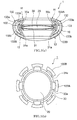
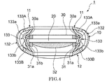
- the device 10 includes a first connecting portion 132 that connects the outer circumferential portions of the front supporting portion 11 and the rear supporting portion 12 and a second connecting portion 133 that connects the inner circumferential portions of the front supporting portion 11 and the rear supporting portion 12.
- the second connecting portion 133 further includes a front ring connecting portion 133A and a rear ring connecting portion 133B arranged alternately along the circumferential direction.
- the front ring connectingportion 133A includes a plurality of connecting pieces provided at equal intervals along the circumferential direction of the front supporting portion 11 and the rear supporting portion 12, a bent portion 133a is formed at a position closer to the front side than the optical portion 10, and the front ring member 30 is connected to the bent portion 133a with the lateral branch 30a interposed.
- the rear ring connecting portion 133B includes a plurality of connecting pieces provided at equal intervals along the circumferential direction of the front supporting portion 11 and the rear supporting portion 12, a bent portion 133b is formed at a position closer to the rear side than the optical portion 10, and the rear ring member 31 is connected to the bent portion 133b with the lateral branch 31a interposed.
- the bent portion 133a of the front ring connecting port ion 133A and the bent portion 133b of the rear ring connecting portion 133B move in the radially outward direction.
- the lateral branches 30a and 31a are deformed in such a manner that the attitude thereof changes such that the lateral branch gradually faces in the planar direction from the front-back direction.
- the front ring member 30 connected to the lateral branch 30a moves in a forward direction, and the downward pressing of the front surface of the circumferential portion 22 decreases gradually and finally disappears substantially.
- the rear ring member 30 connected to the lateral branch 31a moves in a backward direction, and the upward pressing of the rear surface of the circumferential portion 22 of the optical portion 20 decreases and finally disappears substantially.
- the front ring member 30 rarely presses the front surface of the circumferential portion 22 and the rear ring member 31 rarely presses the rear surface of the circumferential portion 22, whereby force is not applied to the optical portion 20 in the direction of compressing the optical portion 20. Due to this, since the optical portion 20 is elastically deformed by being relaxed up to the original shape, it is possible to decrease the curvature of the central portion 21 of the optical portion 20.
- the bent portion 133a of the front ring connecting portion 133A and the bent portion 133b of the rear ring connecting portion 133B move in the radially inward direction.
- the lateral branches 30a and 31a are deformed in such a manner that the attitude thereof changes such that the lateral branch gradually faces in the front-back direction from the planar direction.
- the front ring member 30 connected to the lateral branch 30a moves in the backward direction and presses the front surface of the circumferential portion 22 toward the lower side.
- the rear ringmember 30 connected to the lateral branch 31a moves in the forward direction and presses the rear surface of the circumferential portion 22 of the optical portion 20 toward the upper side.
- the front ring member 30 presses the front surface of the circumferential portion 22 toward the lower side and the rear ring member 31 presses the rear surface of the circumferential portion 22 toward the upper side whereby force is applied to the circumferential portion 22 of the optical portion 20 in the direction of compressing the circumferential portion 22. Due to this, since the central portion 21 of the optical portion 20 greatly swells from the front ring member 30 and the rear ring member 31, it is possible to increase the curvature of the central portion 21 of the optical portion 20.
- a convex lens 32 having a refractive power corresponding to the symptom of a patient is fitted to the opening 31b of the rear ring member 31.
- the optical portion which is elastically deformable can be used for the purpose of obtaining the accommodation power mainly and the convex lens 32 provided in the rear ring member 31 can be used for obtaining a refractive power corresponding to the symptom of a patient. Due to this, the optical portion 20 which is elastically deformable is easily folded when it is formed in a flat shape and can be inserted into the eye from a small incised wound of the lens capsule.
- the convex lens 32 provided in the rear ring member 31 supplements the refractive power after surgery mainly, it is possible to reduce a refraction error (a difference between a target refractive value before surgery and an actual refractive value after surgery) of the refractive power after surgery.
- the circumferential portion 22 of the optical portion 20 may have a thickness of 20 to 100 ⁇ m
- the central portion 21 may have a thickness of 5 to 20 ⁇ m
- the circumferential portion 22 may be thicker than the central portion 21.
- the optical portion 20 is formed so that the thickness of the elastic film gradually increases as it advances from the circumferential portion 22 toward the central portion 21. According to this configuration, a local deformation of the circumferential portion 22 of the optical portion 20 decreases, and the circumferential portion 22 is likely to be deformed generally uniformly.
- the central portion 21 of the optical portion20 isalsolikelytobe deformed uniformly.
- the curvature of the optical portion 20 can be changed effectively.
- the optical portion 20 may have a bulging portion formed at a front end and/or a rear end of the thick portion of the elastic film so as to swell toward an inner side. According to this configuration, when the optical portion 20 is deformed, the circumferential portion 22 of the optical portion 20 iseasily constricted near the bulging portion. As a result, since the central portion 21 of the optical portion 20 is likely to swell, the curvature of the optical portion 20 can be changed effectively.
- the optical portion 20 may be formed so that a refractive index of the flowable substance gradually increases toward the center of the optical portion.
- the optical portion 20 may be partitioned in the front-back direction and a segment including the center of the optical portion may have a larger refractive index than the refractive indices of the other segments. According to this configuration, since the closer to the center, the larger the refractive index like a human lens, it is possible to create a large change in the refractive index by a small deformation of the optical portion.
- the optical portion 20 may have a core member formed at the center and having larger rigidity than the flowable substance. According to this configuration, when the optical portion 20 applies force directly or indirectly from the connecting portion, since the flowable substance present around the core substance applies force to the elastic film efficiently, the curvature of the optical portion 20 can be changed efficiently.
- the core member may be a convex lens having a refractive power corresponding to a symptom of a patient.
- the optical portion 20 can be used for the purpose of obtaining the accommodation power mainly, and the convex lens provided in the optical portion 20 can be used for the purpose of obtaining a refractive power corresponding to the symptom of a patient.
- the optical portion 20 may have an injector for injecting the flowable substance into the optical portion.
- an injector for injecting the flowable substance into the optical portion.
- the lens capsule expanding device 10 may have a convex lens or a concave lens provided in the rear supporting portion 12 and having a refractive power corresponding to a symptom of a patient.
- the optical portion which is elastically deformable can be used for the purpose of obtaining the accommodation power mainly, and the convex lens or the concave lens provided in the rear supporting portion 12 can be used for the purpose of obtaining a refractive power corresponding to the symptom of a patient. Due to this, the optical portion 20 which is elastically deformable is easily folded when it is formed in a flat shape and can be inserted into the eye from a small incised wound of the lens capsule.
- the convex lens or the concave lens provided in the rear supporting portion supplements the refractive power after surgery mainly, it is possible to reduce a refraction error (a difference between a target refractive value before surgery and an actual refractive value after surgery) of the refractive power after surgery.
Landscapes
- Health & Medical Sciences (AREA)
- Ophthalmology & Optometry (AREA)
- Cardiology (AREA)
- Oral & Maxillofacial Surgery (AREA)
- Transplantation (AREA)
- Engineering & Computer Science (AREA)
- Biomedical Technology (AREA)
- Heart & Thoracic Surgery (AREA)
- Vascular Medicine (AREA)
- Life Sciences & Earth Sciences (AREA)
- Animal Behavior & Ethology (AREA)
- General Health & Medical Sciences (AREA)
- Public Health (AREA)
- Veterinary Medicine (AREA)
- Prostheses (AREA)
Applications Claiming Priority (2)
| Application Number | Priority Date | Filing Date | Title |
|---|---|---|---|
| JP2013257870 | 2013-12-13 | ||
| PCT/JP2014/082738 WO2015087931A1 (fr) | 2013-12-13 | 2014-12-10 | Lentille intraoculaire réglable |
Publications (2)
| Publication Number | Publication Date |
|---|---|
| EP3081192A1 true EP3081192A1 (fr) | 2016-10-19 |
| EP3081192A4 EP3081192A4 (fr) | 2017-08-09 |
Family
ID=53371230
Family Applications (2)
| Application Number | Title | Priority Date | Filing Date |
|---|---|---|---|
| EP14870621.1A Withdrawn EP3081193A4 (fr) | 2013-12-13 | 2014-12-10 | Lentille intraoculaire reglable |
| EP14869790.7A Withdrawn EP3081192A4 (fr) | 2013-12-13 | 2014-12-10 | Lentille intraoculaire réglable |
Family Applications Before (1)
| Application Number | Title | Priority Date | Filing Date |
|---|---|---|---|
| EP14870621.1A Withdrawn EP3081193A4 (fr) | 2013-12-13 | 2014-12-10 | Lentille intraoculaire reglable |
Country Status (4)
| Country | Link |
|---|---|
| US (2) | US9968442B2 (fr) |
| EP (2) | EP3081193A4 (fr) |
| JP (2) | JP2015131104A (fr) |
| WO (2) | WO2015087931A1 (fr) |
Cited By (1)
| Publication number | Priority date | Publication date | Assignee | Title |
|---|---|---|---|---|
| EP4046598A4 (fr) * | 2019-10-17 | 2024-03-27 | Mirai Eye Inc. | Lentille intraoculaire d'accommodation |
Families Citing this family (22)
| Publication number | Priority date | Publication date | Assignee | Title |
|---|---|---|---|---|
| EP2806828B1 (fr) | 2012-01-24 | 2021-07-21 | The Regents of The University of Colorado, A Body Corporate | Conceptions de lentilles intraoculaires modulaires et procédés s'y rapportant |
| US8900300B1 (en) | 2012-02-22 | 2014-12-02 | Omega Ophthalmics Llc | Prosthetic capsular bag and method of inserting the same |
| AU2015219461B2 (en) | 2014-02-18 | 2019-10-31 | Alcon Inc. | Modular intraocular lens designs, tools and methods |
| AU2015277207B2 (en) | 2014-06-19 | 2018-03-29 | Omega Ophthalmics Llc | Prosthetic capsular devices, systems, and methods |
| EP3250152B1 (fr) | 2015-01-30 | 2025-03-12 | Alcon Inc. | Inserteur pour insertion d'une base et d'une lentille intraoculaire modulaire dans un oeil |
| US9358103B1 (en) | 2015-02-10 | 2016-06-07 | Omega Ophthalmics Llc | Prosthetic capsular devices, systems, and methods |
| CN108348327B (zh) | 2015-11-04 | 2021-10-01 | 克拉维斯塔医疗有限公司 | 模块化人工晶状体设计、工具和方法 |
| JP6824576B2 (ja) * | 2015-11-25 | 2021-02-03 | 株式会社Mirai Eye | 調節眼内レンズ |
| WO2017109624A1 (fr) * | 2015-12-22 | 2017-06-29 | Novartis Ag | Lentille intraoculaire d'accommodation |
| US11045309B2 (en) * | 2016-05-05 | 2021-06-29 | The Regents Of The University Of Colorado | Intraocular lens designs for improved stability |
| US9993336B2 (en) | 2016-06-06 | 2018-06-12 | Omega Ophthalmics Llc | Prosthetic capsular devices, systems, and methods |
| WO2018075932A1 (fr) | 2016-10-21 | 2018-04-26 | Omega Ophthalmics Llc | Dispositifs capsulaires prothétiques, systèmes et procédés |
| US11213384B2 (en) * | 2017-03-01 | 2022-01-04 | Eye-Pcr B.V. | Devices for reconstruction of a lens capsule after cataract surgery |
| US10548719B2 (en) | 2017-03-01 | 2020-02-04 | Eye-Pcr B.V. | Devices for reconstruction of a lens capsule after cataract surgery |
| US11382736B2 (en) | 2017-06-27 | 2022-07-12 | Alcon Inc. | Injector, intraocular lens system, and related methods |
| CN108272534A (zh) * | 2018-01-23 | 2018-07-13 | 上海理工大学 | 一种可连续变焦的人工晶状体 |
| WO2019169084A1 (fr) | 2018-03-01 | 2019-09-06 | Ellis Forrest J | Lentille intraoculaire avec lèvres de centrage |
| AU2019249216B2 (en) | 2018-04-06 | 2024-07-18 | Omega Ophthalmics Llc | Prosthetic capsular devices, systems, and methods |
| WO2020226711A1 (fr) | 2019-05-03 | 2020-11-12 | JelliSee Ophthalmics Inc. | Lentilles intraoculaires avec optique à changement de forme |
| DE102019123295B4 (de) | 2019-08-30 | 2021-04-15 | Carl Zeiss Meditec Ag | Intraokularlinse mit spezifischer, dreidimensional gekrümmter Haptik |
| WO2021211117A1 (fr) | 2020-04-15 | 2021-10-21 | Carl Zeiss Meditec Ag | Lentille intraoculaire et appareil de traitement |
| WO2022082170A1 (fr) | 2020-10-12 | 2022-04-21 | Omega Ophthalmics Llc | Dispositifs capsulaires prothétiques, systèmes et procédés |
Family Cites Families (28)
| Publication number | Priority date | Publication date | Assignee | Title |
|---|---|---|---|---|
| IL121327A (en) | 1997-07-16 | 2003-12-10 | Henry M Israel | Intraocular lens assembly |
| US6117171A (en) * | 1998-12-23 | 2000-09-12 | Skottun; Bernt Christian | Encapsulated accommodating intraocular lens |
| US6488708B2 (en) * | 1999-04-09 | 2002-12-03 | Faezeh Sarfarazi | Open chamber, elliptical, accommodative intraocular lens system |
| US7037338B2 (en) * | 2001-12-14 | 2006-05-02 | Toshiyuki Nagamoto | Intraocular ring assembly and artificial lens kit |
| US20050021139A1 (en) * | 2003-02-03 | 2005-01-27 | Shadduck John H. | Ophthalmic devices, methods of use and methods of fabrication |
| US8048155B2 (en) * | 2002-02-02 | 2011-11-01 | Powervision, Inc. | Intraocular implant devices |
| JP4473217B2 (ja) | 2002-10-25 | 2010-06-02 | クエスト ヴィジョン テクノロジー, アイエヌシー. | 埋め込み可能な人工水晶体 |
| US20040082993A1 (en) | 2002-10-25 | 2004-04-29 | Randall Woods | Capsular intraocular lens implant having a refractive liquid therein |
| US8034107B2 (en) * | 2005-09-01 | 2011-10-11 | Stenger Donald C | Accommodating intraocular lens |
| JP4927371B2 (ja) | 2005-09-28 | 2012-05-09 | 興和株式会社 | 眼内レンズ |
| US20120330415A1 (en) * | 2011-06-23 | 2012-12-27 | Anew Optics, Inc. | Haptic devices for intraocular lens |
| CA2673388C (fr) * | 2006-12-22 | 2015-11-24 | Amo Groningen B.V. | Lentille intraoculaire d'accommodation, systeme de lentille et structure pour lentille |
| US8048156B2 (en) * | 2006-12-29 | 2011-11-01 | Abbott Medical Optics Inc. | Multifocal accommodating intraocular lens |
| US8034106B2 (en) * | 2007-02-02 | 2011-10-11 | Adoptics Ag | Interfacial refraction accommodating lens (IRAL) |
| KR100843454B1 (ko) * | 2007-03-08 | 2008-07-03 | 박경진 | 안구내렌즈 지지체 |
| KR100807939B1 (ko) | 2007-03-08 | 2008-02-28 | 박경진 | 안구내렌즈 조립체 |
| US20110313522A1 (en) * | 2008-11-26 | 2011-12-22 | Anew Optics, Inc. | Pseudophakic Accommodating Intraocular Lens |
| AU2010203427B2 (en) * | 2009-01-09 | 2017-05-18 | Alcon Inc. | Intraocular lenses and methods of accounting for capsule size variability and post-implant changes in the eye |
| WO2010089689A1 (fr) * | 2009-02-08 | 2010-08-12 | Nir Betser | Ensemble de lentille intra-oculaire accommodative |
| US20110071628A1 (en) * | 2009-09-24 | 2011-03-24 | Rainbow Medical Ltd. | Accommodative intraocular lens |
| US9114005B2 (en) * | 2009-11-17 | 2015-08-25 | Akkolens International B.V. | Accommodative intraocular lens driven by ciliary mass |
| US20120296424A1 (en) * | 2010-01-26 | 2012-11-22 | Nir Betser | Accomodating intraocular lens |
| ES2368984B1 (es) * | 2010-02-19 | 2012-10-08 | Luis Olcina Portilla | Lente intraocular acomodativa. |
| WO2013176979A1 (fr) | 2012-05-25 | 2013-11-28 | California Institute Of Technology | Lentille intraoculaire composite à accommodation et procédés associés |
| US8834566B1 (en) | 2012-09-12 | 2014-09-16 | David Jones | Presbyopia-correcting intraocular lens implant |
| WO2014099759A1 (fr) * | 2012-12-21 | 2014-06-26 | Novartis Ag | Système de cristallin artificiel pour vision monofocale au niveau de multiples foyers prédéfinis |
| WO2014100325A1 (fr) * | 2012-12-21 | 2014-06-26 | Abbott Medical Optics Inc. | Lentille intraoculaire accommodative permettant un changement de puissance progressif |
| US10182905B2 (en) * | 2015-06-10 | 2019-01-22 | Richard F. Honigsbaum | Anterior-posterior-capsule-actuated hydraulic accommodative intraocular lenses and lens systems |
-
2014
- 2014-12-10 US US15/103,540 patent/US9968442B2/en active Active
- 2014-12-10 JP JP2014249710A patent/JP2015131104A/ja active Pending
- 2014-12-10 EP EP14870621.1A patent/EP3081193A4/fr not_active Withdrawn
- 2014-12-10 EP EP14869790.7A patent/EP3081192A4/fr not_active Withdrawn
- 2014-12-10 WO PCT/JP2014/082738 patent/WO2015087931A1/fr not_active Ceased
- 2014-12-10 WO PCT/JP2014/082735 patent/WO2015087930A1/fr not_active Ceased
- 2014-12-10 JP JP2014249829A patent/JP2015131105A/ja active Pending
- 2014-12-10 US US15/103,610 patent/US10028823B2/en active Active
Cited By (1)
| Publication number | Priority date | Publication date | Assignee | Title |
|---|---|---|---|---|
| EP4046598A4 (fr) * | 2019-10-17 | 2024-03-27 | Mirai Eye Inc. | Lentille intraoculaire d'accommodation |
Also Published As
| Publication number | Publication date |
|---|---|
| WO2015087931A1 (fr) | 2015-06-18 |
| JP2015131104A (ja) | 2015-07-23 |
| EP3081193A1 (fr) | 2016-10-19 |
| US20160310263A1 (en) | 2016-10-27 |
| US10028823B2 (en) | 2018-07-24 |
| JP2015131105A (ja) | 2015-07-23 |
| EP3081193A4 (fr) | 2017-08-16 |
| WO2015087930A1 (fr) | 2015-06-18 |
| US9968442B2 (en) | 2018-05-15 |
| US20160310264A1 (en) | 2016-10-27 |
| EP3081192A4 (fr) | 2017-08-09 |
Similar Documents
| Publication | Publication Date | Title |
|---|---|---|
| US9968442B2 (en) | Accommodating intraocular lens | |
| US12090044B2 (en) | Accommodating intraocular lens | |
| US10758339B2 (en) | Intraocular lens assembly | |
| EP2939636A1 (fr) | Dispositif d'extension de cristalloïde | |
| EP2997934A1 (fr) | Lentille intraoculaire ajustable | |
| JP2018507049A (ja) | 二重光学部型曲率変化調節可能iol | |
| EP1462071A2 (fr) | Lentille intra-oculaire permettant l'accommodation | |
| US11547553B2 (en) | Accommodative intraocular lens | |
| JP2019507627A (ja) | 固定された非調節時の屈折力状態を有する二重光学部型曲率変化調節可能iol | |
| WO1996025126A1 (fr) | Lentille intraoculaire d'accommodation presentant des parties haptiques en forme de t | |
| KR102493628B1 (ko) | 순응형 안내 렌즈 | |
| JP2009518148A (ja) | 調節アーチレンズ | |
| AU2013363516A1 (en) | Curvature changing accommodative intraocular lens | |
| EP4046598A1 (fr) | Lentille intraoculaire d'accommodation | |
| EP3960125B1 (fr) | Lentille intraoculaire d'accommodation | |
| US20150134059A1 (en) | Deformable accommodative intraocular lens | |
| JP6824576B2 (ja) | 調節眼内レンズ |
Legal Events
| Date | Code | Title | Description |
|---|---|---|---|
| PUAI | Public reference made under article 153(3) epc to a published international application that has entered the european phase |
Free format text: ORIGINAL CODE: 0009012 |
|
| 17P | Request for examination filed |
Effective date: 20160620 |
|
| AK | Designated contracting states |
Kind code of ref document: A1 Designated state(s): AL AT BE BG CH CY CZ DE DK EE ES FI FR GB GR HR HU IE IS IT LI LT LU LV MC MK MT NL NO PL PT RO RS SE SI SK SM TR |
|
| AX | Request for extension of the european patent |
Extension state: BA ME |
|
| RAP1 | Party data changed (applicant data changed or rights of an application transferred) |
Owner name: XLENS TECHNOLOGIES INC. |
|
| DAX | Request for extension of the european patent (deleted) | ||
| RIN1 | Information on inventor provided before grant (corrected) |
Inventor name: AKURA, JUNSUKE |
|
| A4 | Supplementary search report drawn up and despatched |
Effective date: 20170707 |
|
| RIC1 | Information provided on ipc code assigned before grant |
Ipc: A61F 2/16 20060101AFI20170704BHEP |
|
| STAA | Information on the status of an ep patent application or granted ep patent |
Free format text: STATUS: THE APPLICATION IS DEEMED TO BE WITHDRAWN |
|
| 18D | Application deemed to be withdrawn |
Effective date: 20180206 |