EP3081252B1 - Système de dilatation vertébrale à ballonnet - Google Patents
Système de dilatation vertébrale à ballonnet Download PDFInfo
- Publication number
- EP3081252B1 EP3081252B1 EP14869555.4A EP14869555A EP3081252B1 EP 3081252 B1 EP3081252 B1 EP 3081252B1 EP 14869555 A EP14869555 A EP 14869555A EP 3081252 B1 EP3081252 B1 EP 3081252B1
- Authority
- EP
- European Patent Office
- Prior art keywords
- balloon
- tube
- vertebral
- distal end
- pushing
- Prior art date
- Legal status (The legal status is an assumption and is not a legal conclusion. Google has not performed a legal analysis and makes no representation as to the accuracy of the status listed.)
- Active
Links
Images



Classifications
-
- A—HUMAN NECESSITIES
- A61—MEDICAL OR VETERINARY SCIENCE; HYGIENE
- A61B—DIAGNOSIS; SURGERY; IDENTIFICATION
- A61B17/00—Surgical instruments, devices or methods
- A61B17/56—Surgical instruments or methods for treatment of bones or joints; Devices specially adapted therefor
- A61B17/58—Surgical instruments or methods for treatment of bones or joints; Devices specially adapted therefor for osteosynthesis, e.g. bone plates, screws or setting implements
- A61B17/88—Osteosynthesis instruments; Methods or means for implanting or extracting internal or external fixation devices
- A61B17/885—Tools for expanding or compacting bones or discs or cavities therein
- A61B17/8852—Tools for expanding or compacting bones or discs or cavities therein capable of being assembled or enlarged, or changing shape, inside the bone or disc
- A61B17/8855—Tools for expanding or compacting bones or discs or cavities therein capable of being assembled or enlarged, or changing shape, inside the bone or disc inflatable, e.g. kyphoplasty balloons
-
- A—HUMAN NECESSITIES
- A61—MEDICAL OR VETERINARY SCIENCE; HYGIENE
- A61B—DIAGNOSIS; SURGERY; IDENTIFICATION
- A61B17/00—Surgical instruments, devices or methods
- A61B17/56—Surgical instruments or methods for treatment of bones or joints; Devices specially adapted therefor
- A61B17/58—Surgical instruments or methods for treatment of bones or joints; Devices specially adapted therefor for osteosynthesis, e.g. bone plates, screws or setting implements
- A61B17/88—Osteosynthesis instruments; Methods or means for implanting or extracting internal or external fixation devices
- A61B17/8802—Equipment for handling bone cement or other fluid fillers
- A61B17/8805—Equipment for handling bone cement or other fluid fillers for introducing fluid filler into bone or extracting it
-
- A—HUMAN NECESSITIES
- A61—MEDICAL OR VETERINARY SCIENCE; HYGIENE
- A61B—DIAGNOSIS; SURGERY; IDENTIFICATION
- A61B17/00—Surgical instruments, devices or methods
- A61B17/16—Instruments for performing osteoclasis; Drills or chisels for bones; Trepans
- A61B17/1642—Instruments for performing osteoclasis; Drills or chisels for bones; Trepans for producing a curved bore
-
- A—HUMAN NECESSITIES
- A61—MEDICAL OR VETERINARY SCIENCE; HYGIENE
- A61B—DIAGNOSIS; SURGERY; IDENTIFICATION
- A61B17/00—Surgical instruments, devices or methods
- A61B17/56—Surgical instruments or methods for treatment of bones or joints; Devices specially adapted therefor
- A61B17/58—Surgical instruments or methods for treatment of bones or joints; Devices specially adapted therefor for osteosynthesis, e.g. bone plates, screws or setting implements
- A61B17/88—Osteosynthesis instruments; Methods or means for implanting or extracting internal or external fixation devices
- A61B17/8802—Equipment for handling bone cement or other fluid fillers
- A61B17/8805—Equipment for handling bone cement or other fluid fillers for introducing fluid filler into bone or extracting it
- A61B17/8811—Equipment for handling bone cement or other fluid fillers for introducing fluid filler into bone or extracting it characterised by the introducer tip, i.e. the part inserted into or onto the bone
-
- A—HUMAN NECESSITIES
- A61—MEDICAL OR VETERINARY SCIENCE; HYGIENE
- A61B—DIAGNOSIS; SURGERY; IDENTIFICATION
- A61B17/00—Surgical instruments, devices or methods
- A61B17/56—Surgical instruments or methods for treatment of bones or joints; Devices specially adapted therefor
- A61B17/58—Surgical instruments or methods for treatment of bones or joints; Devices specially adapted therefor for osteosynthesis, e.g. bone plates, screws or setting implements
- A61B17/88—Osteosynthesis instruments; Methods or means for implanting or extracting internal or external fixation devices
- A61B17/885—Tools for expanding or compacting bones or discs or cavities therein
- A61B17/8852—Tools for expanding or compacting bones or discs or cavities therein capable of being assembled or enlarged, or changing shape, inside the bone or disc
-
- A—HUMAN NECESSITIES
- A61—MEDICAL OR VETERINARY SCIENCE; HYGIENE
- A61M—DEVICES FOR INTRODUCING MEDIA INTO, OR ONTO, THE BODY; DEVICES FOR TRANSDUCING BODY MEDIA OR FOR TAKING MEDIA FROM THE BODY; DEVICES FOR PRODUCING OR ENDING SLEEP OR STUPOR
- A61M29/00—Dilators with or without means for introducing media, e.g. remedies
- A61M29/02—Dilators made of swellable material
-
- A—HUMAN NECESSITIES
- A61—MEDICAL OR VETERINARY SCIENCE; HYGIENE
- A61B—DIAGNOSIS; SURGERY; IDENTIFICATION
- A61B17/00—Surgical instruments, devices or methods
- A61B2017/00831—Material properties
- A61B2017/00853—Material properties low friction, hydrophobic and corrosion-resistant fluorocarbon resin coating (ptf, ptfe, polytetrafluoroethylene)
Definitions
- the present disclosure relates to the field of medical equipment, and more particularly, to a vertebral balloon dilation system for use in percutaneous kyphoplasty (PKP).
- PGP percutaneous kyphoplasty
- Osteoporotic vertebral compression fracture is a common disease harmful to the health of middle-aged and elderly people.
- traditional treatment methods are conservative for the most part and include bed rest, drug analgesia, and external fixation with orthosis, etc.. These traditional treatment methods often result in a further loss of bone mass and an exacerbation of osteoporosis, thus forming a vicious cycle, while an open surgery can easily result in failures of internal fixation due to the poor health condition of the patient or insufficient fixation strength of screws.
- WO 2012/134592 describes an apparatus assembly comprising a conforming catheter shaft an expandable element having an expandable balloon portion bonded at the distal end of the catheter shaft, and a fluid passageway extending from a proximal end of the catheter shaft to the interior of the balloon portion of the expandable element.
- PVP percutaneous vertebroplasty
- the drawbacks of such surgery include that it is only possible to fix the injured vertebral body with deformity and alleviate the pain, but impossible to restore the vertebral height or correct the kyphotic deformity. Moreover, since the low-viscosity bone cement is injected into the vertebral cancellous bone directly under a relatively higher pressure, it is difficult to control the flow, and the leakage rate of the bone cement is higher, which is within the range of 30% - 67%, as reported in references.
- the technique includes the following steps: inserting a dilatable balloon into a collapsed vertebral body by percutaneous puncture, lifting up the endplate by the dilation of the balloon, restoring the height of the vertebral body and correcting the kyphotic deformity, thereby forming a hollow cavity surrounded by the bone shell in the vertebral body and injecting it with the high-viscosity bone cement under a relatively lower pressure.
- a working channel has to be established primarily with a puncture needle and a working sleeve tube, then a working cavity for the un-dilated balloon is drilled with a bone drill, and finally the balloon is inserted into the vertebral body.
- the surgical procedure is complex. Because of the structure of the vertebral body, the balloon dilation has to be operated at both sides of each vertebral body in order to maintain the biomechanical force balance of the vertebral body. Furthermore, the surgery has to be operated under X-ray monitoring, therefore, the more complicated the surgical procedures, the longer the time spent, the greater the damage to the health of the doctor, and the higher the level of physical strength of the doctor required.
- the balloon dilation operated at both sides of the vertebral body may thus result in a greater trauma to the patient a higher incidence of complications, and may increase the economical burden of the patient.
- the above defects will become more significant in the case of multi-segmental vertebral lesions.
- the present disclosure aims to provide a vertebral balloon dilation system, which can be fed to the center or to the opposite side of the vertebral body simply by puncturing at only one side without drilling with a bone drill to form a cavity before feeding the dilatable balloon.
- a dilatable balloon is fed to the center or the opposite side of the vertebral body with a liner core provided with a curved section at its distal end, and then a developer solution is injected into the balloon by means of a pushing tube, thereby simplifying surgical procedures, shortening the duration of surgery, reducing the incidence of complications, alleviating the pain of patients, and reducing the economical burden of patients.
- a vertebral balloon dilation system comprises a pushing tube and a balloon fixedly connected to a distal end of said pushing tube, wherein said vertebral balloon dilation system can withstand water pressure of no less than 10 atm;
- said pushing tube is a rigid tube, a lumen of said pushing tube is in communication with an interior of said balloon; and
- said balloon is made of a membrane material, a distal end of said balloon is fixedly connected with a sealing head that is closed at its distal end and has a blind hole at its proximal end, wherein said blind hole has an opening towards the interior of said balloon.
- Said vertebral balloon dilation system further comprises a sleeve tube and a liner core, wherein said liner core is slidably inserted into said pushing tube, a distal end part of said liner core is a curved section, which protrudes out of the distal end of said pushing tube, the distal end of said liner core is inserted into said blind hole of said sealing head through said pushing tube and the interior of said balloon, and said balloon is configured to wrap up the curved section of the liner core; a distal end part of said sleeve tube is a flexible section, whereas a proximal end part of said sleeve tube is a rigid section, wherein said flexible section is rigid in the radial direction and said sleeve tube is sleeved on said pushing tube and said balloon; and, when said vertebral balloon dilation system is operated, said sleeve tube slides towards a proximal end of said pushing tube in the axial direction, and said balloon is exposed.
- said sealing head is connected with said balloon in a connection manner selected from binding connection, threaded connection, compression connection, adhesive connection, or welding connection or combinations thereof.
- said membrane material is PTFE membrane.
- said sealing head is made of a rigid material, the distal end of which is in a sharp shape, whereas the distal end of said sleeve tube is sleeved on or connected with said sealing head.
- an end part of said curved section of said liner core is a straight section, which is inserted into said blind hole in said sealing head and reaches the bottom of said blind hole.
- said flexible section of said sleeve tube is cut from a metal tube, formed of a spring, made of a hard medical polymer material, or formed of any combinations of metal materials and polymer materials.
- said balloon is in a banana shape or a dumbbell shape.
- said balloon is foldable in its axial direction, and is configured to wrap up said curved section of the liner core along its circumferential direction.
- said vertebral balloon dilation system further comprises a liner core handle fixedly connected to the proximal end of said liner core, a pushing handle fixedly connected to the proximal end of said pushing tube, and a sleeve tube handle connected to the proximal end of said sleeve tube, wherein said pushing handle includes one or more guide grooves, a distal end of said pushing handle is provided with a stop block for limiting the position of said sleeve tube handle, and said sleeve tube handle is provided with one or more guide blocks engaged with said guide grooves such that while said sleeve tube handle is moved, said sleeve tube will move in the axial direction together with said sleeve tube handle.
- the distal end of said pushing tube and said balloon are fixedly connected by means of hot melt welding, or sintering the proximal end of said balloon entirely to an outside of said pushing tube.
- the present disclosure has the following characteristics and advantages:
- proximal end refers to the end near to the surgical operator, and the distal end refers to the end far away from the surgical operator.
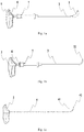
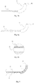
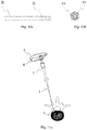
- a vertebral balloon dilation system comprises a balloon 1, a pushing tube 2 fixedly connected to the proximal end of the balloon 1, a sleeve tube 3, and a liner core 4; the vertebral balloon dilation system can withstand the water pressure of no less than 10 atm; the pushing tube 2 is a rigid tube, the lumen of the pushing tube 2 is in communication with the interior of the balloon 1; the balloon 1 is made of a membrane material, the distal end of the balloon 1 is fixedly connected with a sealing head 11, the sealing head 11 is closed at its distal end and has a blind hole 111 at its proximal end, the blind hole 111 has an opening towards the interior of the balloon; the liner core is slidably inserted into the pushing tube, the distal end part of the liner core 4 is a curved section 41, which protrudes out of the distal end of the pushing tube 2, the distal end of
- the distal end of the balloon 1 is fixedly connected with a sealing head 11, the distal end of which is closed, and the sealing head 11 is made of a rigid material.
- the proximal end of the sealing head 11 is provided with a blind hole 111 with an opening towards the interior of said balloon.
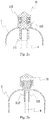
- the head end of the sealing head 11 is in a sharp shape, and the sealing head 11 is provided with a ring-shaped groove 112.
- the distal end of the balloon 1 is tightly bound to the ring-shaped groove 112 of the sealing head 11 by means of wires (threads) 113, and the distal end of the balloon 1 is turned over and wraps up the wires 113.
- the sealing head 11 is provided with an inner core 112', the proximal end of which is provided with an external thread, and the inner core 112' has a blind hole 111.
- the blind hole 111 has an opening towards the interior of the balloon 1, and the distal end of the sealing head 11 is in a sharp shape, and the sealing head 11 is provided with an internal thread.
- the external thread of the inner core 112 and the internal thread of the sealing head 11 are both trapezoidal threads, and the distal end of the balloon 1 is tightly clamped between the external thread of the inner core 112' and the internal thread of the sealing head 11 such that the threaded connection is formed.
- a third embodiment as shown in Figs.
- the sealing head 11 is provided with a fixing ring 112", wherein the distal end of the balloon 1 passes through the inner hole of the fixing ring 112" and then is turned over outwardly to wrap up the fixing ring 112", and the proximal end of the sealing head 11 has several pieces 114 formed by cutting. After the distal end of the balloon 1 is turned over to wrap up the fixing ring 112", it is covered with the sealing head 11, and then the pieces 114 provided at the proximal end of the sealing head 11 are pressed down to fixedly connect the distal end of the balloon 1 with the sealing head 11 and meanwhile the interior of the fixing ring 112" forms the blind hole 111.
- the balloon 1 is formed in a banana shape or a dumbbell shape, and the balloon 1 is made of PTFE (polytetrafluoroethylene) membrane.
- PTFE polytetrafluoroethylene
- the proximal end of the balloon 1 is fixedly connected to the outside of the distal end of the pushing tube 2 by means of hot melt welding or sintering.
- the proximal end of the balloon 1 is hot-melt welded to the distal end of the pushing tube 2.
- the proximal end part of the balloon 1 extends to form a tubular section 12, which is entirely sintered to the external surface of the distal end of the pushing tube 2.
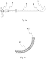
- the distal end part of the liner core 4 is a curved section 41 with the shape memory property.
- the curved section 41 is made of nitinol wires (as shown in Fig. 1c ) or a combination of nitinol wires 411 and polymer material 412 (as shown in Fig. 1e ).
- the end part of the curved section 41 is a straight section 42, which can be slidably inserted to the blind hole 111 of the sealing head 11 and finally reach the bottom of the blind hole 111. After the straight section 42 is inserted into the blind hole 111, the sealing head 11 will not be driven when the liner core 4 is withdrawn, such that the displacement of the balloon 1 can be prevented.
- the balloon 1 is foldable in the axial direction thereof, and wraps up the curved section of the liner core 4 along the circumferential direction thereof.
- the vertebral balloon dilation system further comprises a liner core handle 5 fixedly connected to the proximal end of the liner core 4, a pushing handle 6 fixedly connected to the proximal end of the pushing tube 2, and a sleeve tube handle 7 connected to the proximal end of the sleeve tube 3, wherein the proximal end of the pushing handle 6 is provided with a port in communication with a balloon filling device, the pushing handle 6 is provided with one or more guide grooves 61, the distal end of the pushing handle 6 is provided with a stop block 62 for limiting the position of the sleeve tube handle 7, and the sleeve tube handle 7 is provided with one or more guide blocks 71 engaged with the guide grooves 61 of the pushing handle 6, such that, when the sleeve tube handle 7 is moved, the sleeve tube 3 can move in the axial direction together with the sleeve tube handle 7.
- the distal end part of the sleeve tube 3 is a flexible section 31, whereas the proximal end part thereof is a rigid section 32, wherein the flexible section 31 is rigid in the radial direction, the sleeve tube 3 is sleeved on the pushing tube 2 and the balloon 1 (as shown in Fig. 1b ), and the distal end of the sleeve tube 3 is sleeved on or connected to the sealing head 11 (as shown in Fig. 5 ).
- the sleeve tube handle 7 is operated, the sleeve tube 3 is moved axially to the proximal end of the pushing tube 2, and the balloon 1 is exposed.
- the flexible section of the sleeve tube 3 is cut from a metal tube, formed of a spring, or made of a hard medical polymer material or any combinations of metal materials or polymer materials.
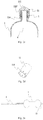
- the flexible section 31 of the sleeve tube 3 is cut from a metal tube, and the rigid section 32 is a metal tube.
- the flexible section 31 of the sleeve tube 3 is formed of a metal spring, and the rigid section 32 is a metal tube, wherein the proximal end of the flexible section 31 is welded to the distal end of the rigid section 32.
- Figs. 8 the flexible section 31 of the sleeve tube 3 is formed of a metal spring, and the rigid section 32 is a metal tube, wherein the proximal end of the flexible section 31 is welded to the distal end of the rigid section 32.
- the flexible section 31 of the sleeve tube 3 is formed with a curved section made of a medical polymer material (preferably, PEEK) by heat-setting.
- a medical polymer material preferably, PEEK
- the flexible section 31 of the sleeve tube 3 is made of a combination of metal material 311 and medical polymer material 312, and the rigid section 32 is made of a metal material.
- the sealing head 11, the inner core 112' and the fixing ring 112" are made of a metal material (preferably, pure titanium) or a hard medical polymer material (preferably, PEEK).
- the balloon 1 is made of a medical polymer material (preferably, expanded PTFE).
- the pushing tube 2 is formed of a metal tube (preferably, 304 stainless steel), the flexible section 31 of the sleeve tube 3 is cut from a metal tube, formed of a spring or shaped from a medical polymer material (preferably, PEEK), and the rigid section 32 of the sleeve tube 3 is formed of a metal tube or made of a medical polymer material (preferably, PEEK).
- the liner core 4 is made of shape memory alloy (preferably, nitinol).
- the sleeve tube handle 7, the pushing handle 6 and the liner core handle 5 are made of a medical polymer material (preferably, POM).
- the vertebral balloon dilation system is inserted into the vertebral body through the working channel up to a predetermined position under the observation with a C-arm, and during the procedure, the liner core 4 has the following functions:
- the sleeve tube handle 7 is moved towards the proximal end to make the sleeve tube 3 move backwards slowly until the balloon 1 is exposed entirely, at this time, the liner core handle 5 is pulled to withdraw the liner core 4 completely, and after that, the balloon filling device is coupled to the pushing handle 6 to inject developer solution to the balloon 1 through the pushing tube 2 until the balloon 1 is dilated.
- a negative pressure is formed in the balloon 1, then the balloon is withdrawn out of the body, and finally, the bone cement is injected to the vertebral body through the working channel.
Landscapes
- Health & Medical Sciences (AREA)
- Life Sciences & Earth Sciences (AREA)
- Surgery (AREA)
- Orthopedic Medicine & Surgery (AREA)
- Veterinary Medicine (AREA)
- General Health & Medical Sciences (AREA)
- Public Health (AREA)
- Engineering & Computer Science (AREA)
- Biomedical Technology (AREA)
- Heart & Thoracic Surgery (AREA)
- Animal Behavior & Ethology (AREA)
- Molecular Biology (AREA)
- Medical Informatics (AREA)
- Nuclear Medicine, Radiotherapy & Molecular Imaging (AREA)
- Vascular Medicine (AREA)
- Anesthesiology (AREA)
- Hematology (AREA)
- Oral & Maxillofacial Surgery (AREA)
- Dentistry (AREA)
- Prostheses (AREA)
- Surgical Instruments (AREA)
Claims (10)
- Système de dilatation vertébrale à ballonnet comprenant un tube de poussée (2) et un ballonnet (1) raccordé, de manière fixe, à une extrémité distale dudit tube de poussée (2), dans lequel :ledit système de dilatation vertébrale à ballonnet peut résister à la pression de l'eau d'une valeur non inférieure à 10 atm ; ledit tube de poussée (2) est un tube rigide, une lumière dudit tube de poussée (2) est en communication avec un intérieur dudit ballonnet (1) ; etledit ballonnet (1) est réalisé avec un matériau de membrane, une extrémité distale dudit ballonnet est raccordée, de manière fixe, avec une tête d'étanchéité (11) qui est fermée au niveau de son extrémité distale et a un trou borgne (111) au niveau de son extrémité proximale, dans lequel ledit trou borgne a une ouverture vers l'intérieur dudit ballonnet ;caractérisé en ce que :ledit système de dilatation vertébrale à ballonnet comprend en outre un tube de manchon (3) et un noyau de revêtement (4), dans lequel ledit noyau de revêtement (4) est inséré, de manière coulissante, dans ledit tube de poussée (2), une partie d'extrémité distale dudit noyau de revêtement (4) est une section incurvée (41) qui fait saillie de l'extrémité distale dudit tube de poussée (2), une extrémité distale dudit noyau de revêtement (4) est insérée dans ledit trou borgne (111) de ladite tête d'étanchéité (11) à travers ledit tube de poussée (2) et l'intérieur dudit ballonnet (1), et ledit ballonnet (1) est configuré pour envelopper la section incurvée (41) du noyau de revêtement (4) ; une partie d'extrémité distale dudit tube de manchon (3) est une section flexible (31), alors qu'une partie d'extrémité proximale dudit tube de manchon est une section rigide (32), dans lequel ladite section flexible (31) est rigide dans la direction radiale, et ledit tube de manchon (3) est emmanché sur ledit tube de poussée (2) et ledit ballonnet (1) ; etlorsque ledit système de dilatation vertébrale à ballonnet est actionné, ledit tube de manchon (3) coulisse vers une extrémité proximale dudit tube de poussée (2) dans la direction axiale, et ledit ballonnet (1) est exposé.
- Système de dilatation vertébrale à ballonnet selon la revendication 1, caractérisé en ce que : ladite tête d'étanchéité (11) est raccordée avec ledit ballonnet (1) par raccordement sélectionné parmi un raccordement de liaison, un raccordement fileté, un raccordement par compression, un raccordement adhésif ou un raccordement par soudage ou leurs combinaisons.
- Système de dilatation vertébrale à ballonnet selon la revendication 1, caractérisé en ce que : ledit matériau de membrane est une membrane en polytétrafluoroéthylène.
- Système de dilatation vertébrale à ballonnet selon la revendication 1, caractérisé en ce que : ladite tête d'étanchéité (11) est réalisée avec un matériau rigide, l'extrémité distale de ladite tête d'étanchéité se présente sous une forme tranchante, et l'extrémité distale dudit tube de manchon (3) est emmanchée sur ou raccordée avec ladite tête d'étanchéité (11).
- Système de dilatation vertébrale à ballonnet selon la revendication 1, caractérisé en ce que : une partie d'extrémité de ladite section incurvée (41) dudit noyau de revêtement (4) est une section droite (42), qui est insérée dans ledit trou borgne (111) dans ladite tête d'étanchéité (11) et atteint le fond dudit trou borgne (111) .
- Système de dilatation vertébrale à ballonnet selon la revendication 1, caractérisé en ce que : ladite section flexible (31) dudit tube de manchon (3) est coupée dans un tube métallique, formé avec un ressort, réalisé dans un matériau polymère dur de qualité médicale, ou formé avec n'importe quelle combinaison de matériaux métalliques et de matériaux polymères.
- Système de dilatation vertébrale à ballonnet selon la revendication 1, caractérisé en ce que : ledit ballonnet se présente sous la forme d'une banane ou sous la forme d'une altère.
- Système de dilatation vertébrale à ballonnet selon la revendication 1, caractérisé en ce que : ledit ballonnet (1) peut être plié, dans sa direction axiale, et est configuré pour envelopper ladite section incurvée (41) du noyau de revêtement (4) le long de sa direction circonférentielle.
- Système de dilatation vertébrale à ballonnet selon la revendication 1, caractérisé en ce que : ledit système de dilatation vertébrale à ballonnet comprend en outre une poignée de noyau de revêtement (5) raccordée, de manière fixe, à l'extrémité proximale dudit noyau de revêtement (4), une poignée de poussée (6) raccordée, de manière fixe, à l'extrémité proximale dudit tube de poussée (2), et une poignée de tube de manchon (7) raccordée à l'extrémité proximale dudit tube de manchon (3), dans lequel ladite poignée de poussée (6) comprend une ou plusieurs rainures de guidage (61), une extrémité distale de ladite poignée de poussée (6) est prévue avec un bloc de butée (62) pour limiter la position de ladite poignée de tube de manchon (7), et ladite poignée de tube de manchon (7) est prévue avec un ou plusieurs blocs de guidage (71) mis en prise avec lesdites rainures de guidage (61), de sorte que, alors que ladite poignée de tube de manchon (7) est déplacée, ledit tube de manchon (3) se déplace dans la direction axiale conjointement avec ladite poignée de tube de manchon (7).
- Système de dilatation vertébrale à ballonnet selon la revendication 1, caractérisé en ce que : l'extrémité distale dudit tube de poussée (2) et ledit ballonnet (1) sont raccordés, de manière fixe, par soudage thermofusible ou en frittant l'extrémité proximale dudit ballonnet (1) entièrement sur l'extérieur dudit tube de poussée (2).
Applications Claiming Priority (2)
| Application Number | Priority Date | Filing Date | Title |
|---|---|---|---|
| CN201310671713.6A CN103690228B (zh) | 2013-12-12 | 2013-12-12 | 椎体扩张球囊系统 |
| PCT/CN2014/089873 WO2015085837A1 (fr) | 2013-12-12 | 2014-10-30 | Système de dilatation vertébrale à ballonnet |
Publications (3)
| Publication Number | Publication Date |
|---|---|
| EP3081252A1 EP3081252A1 (fr) | 2016-10-19 |
| EP3081252A4 EP3081252A4 (fr) | 2017-03-15 |
| EP3081252B1 true EP3081252B1 (fr) | 2018-08-22 |
Family
ID=50352009
Family Applications (1)
| Application Number | Title | Priority Date | Filing Date |
|---|---|---|---|
| EP14869555.4A Active EP3081252B1 (fr) | 2013-12-12 | 2014-10-30 | Système de dilatation vertébrale à ballonnet |
Country Status (4)
| Country | Link |
|---|---|
| US (1) | US20160310193A1 (fr) |
| EP (1) | EP3081252B1 (fr) |
| CN (1) | CN103690228B (fr) |
| WO (1) | WO2015085837A1 (fr) |
Cited By (1)
| Publication number | Priority date | Publication date | Assignee | Title |
|---|---|---|---|---|
| US11744627B2 (en) * | 2019-08-16 | 2023-09-05 | Hao ding-jun | Integrated targeted kyphoplasty system |
Families Citing this family (33)
| Publication number | Priority date | Publication date | Assignee | Title |
|---|---|---|---|---|
| US20100298832A1 (en) | 2009-05-20 | 2010-11-25 | Osseon Therapeutics, Inc. | Steerable curvable vertebroplasty drill |
| WO2015057195A1 (fr) | 2013-10-15 | 2015-04-23 | Stryker Corporation | Dispositif permettant de créer un espace vide dans un tissu vivant, comprenant une poignée dotée d'un bouton de commande qui peut être réglé quelle que soit l'orientation de la poignée |
| CN103690228B (zh) * | 2013-12-12 | 2015-11-25 | 宁波华科润生物科技有限公司 | 椎体扩张球囊系统 |
| CN104434280A (zh) * | 2014-12-12 | 2015-03-25 | 上海朗迈医疗器械科技有限公司 | 可控弯治疗椎体压缩性骨折的可膨胀装置 |
| CN104783880B (zh) * | 2015-05-13 | 2017-06-30 | 王洪伟 | 一种椎体后凸成形系统 |
| EP3531934B1 (fr) | 2016-10-27 | 2024-08-21 | Dfine, Inc. | Ostéotome articulé avec canal de distribution de ciment |
| AU2017363356B2 (en) | 2016-11-28 | 2023-02-09 | Dfine, Inc. | Tumor ablation devices and related methods |
| US10470781B2 (en) | 2016-12-09 | 2019-11-12 | Dfine, Inc. | Medical devices for treating hard tissues and related methods |
| EP3565486B1 (fr) | 2017-01-06 | 2021-11-10 | Dfine, Inc. | Ostéotome avec partie distale pour avancement et articulation simultanés |
| CN106730262B (zh) * | 2017-02-16 | 2023-04-07 | 常州凯耀医疗器械有限公司 | 双头椎体扩张器 |
| CN107789100B (zh) * | 2017-12-08 | 2024-04-12 | 河北瑞鹤医疗器械有限公司 | 融合器推入器 |
| CN108771563A (zh) * | 2018-06-01 | 2018-11-09 | 赵群 | 骨水泥防渗漏推入装置 |
| WO2020097339A1 (fr) | 2018-11-08 | 2020-05-14 | Dfine, Inc. | Dispositif d'ablation de tumeurs et systèmes et procédés apparentés |
| CN109431589B (zh) * | 2018-11-20 | 2023-12-08 | 宁波华科润生物科技有限公司 | 一体式多功能椎体成形器械 |
| CN109745114A (zh) * | 2018-11-20 | 2019-05-14 | 宁波华科润生物科技有限公司 | 一种多功能的椎体成形器械 |
| CN109350210B (zh) * | 2018-11-30 | 2024-02-09 | 上海朗迈医疗器械科技有限公司 | 一种单侧椎体成形系统工具 |
| CN109820548B (zh) * | 2018-12-21 | 2020-11-17 | 先健科技(深圳)有限公司 | 封堵器、其制备方法及封堵系统 |
| WO2020219392A2 (fr) * | 2019-04-24 | 2020-10-29 | Stryker Corporation | Systèmes et procédés d'augmentation hors-axe d'un corps vertébral |
| CN110720959B (zh) * | 2019-10-31 | 2024-10-15 | 谢少鹏 | 椎体扩张装置 |
| CN111135430B (zh) * | 2019-11-29 | 2022-12-02 | 东莞市先健医疗有限公司 | 球囊导管 |
| WO2021146015A1 (fr) * | 2020-01-17 | 2021-07-22 | Wright Medical Technology, Inc. | Outils, systèmes et procédés de guidage |
| CN111096786A (zh) * | 2020-02-20 | 2020-05-05 | 苏州爱得科技发展股份有限公司 | 一种弯度可控椎体扩张球囊 |
| CN111214286B (zh) * | 2020-04-24 | 2020-08-25 | 上海凯利泰医疗科技股份有限公司 | 骨填充物释放装置 |
| CN111345883B (zh) * | 2020-04-24 | 2024-09-27 | 上海凯利泰医疗科技股份有限公司 | 骨填充物释放装置 |
| CA3193177A1 (fr) * | 2020-09-22 | 2022-03-31 | Beau Michael Kidman | Systemes et methodes d'augmentation d'un corps vertebral |
| CN112043368A (zh) * | 2020-09-23 | 2020-12-08 | 宁波华科润生物科技有限公司 | 一种囊体呈多凸起型的椎体成形植入器械 |
| CN115487400B (zh) * | 2021-06-18 | 2025-01-10 | 上海加奇生物科技苏州有限公司 | 球囊微导管 |
| CN114699218B (zh) * | 2022-06-08 | 2022-08-16 | 北京天星博迈迪医疗器械有限公司 | 一种自密封球囊 |
| CN115568912B (zh) * | 2022-07-29 | 2024-09-13 | 宁波华科润生物科技有限公司 | 一种定向扩张球囊系统 |
| CN115500926B (zh) * | 2022-09-21 | 2024-09-13 | 宁波华科润生物科技有限公司 | 一种定向扩张球囊系统 |
| CN115486923B (zh) * | 2022-09-21 | 2024-09-13 | 宁波华科润生物科技有限公司 | 一种随液定向扩张球囊系统及随液定向扩张方法 |
| CN115845232B (zh) * | 2022-12-27 | 2025-12-23 | 上海珀利医用材料有限公司 | 一种扩张装置及椎体成形扩张设备 |
| CN121729194A (zh) * | 2023-07-27 | 2026-03-24 | 美敦力欧洲有限公司 | 具有可部署抽取管的可充胀球囊夯 |
Family Cites Families (21)
| Publication number | Priority date | Publication date | Assignee | Title |
|---|---|---|---|---|
| US4261339A (en) * | 1978-03-06 | 1981-04-14 | Datascope Corp. | Balloon catheter with rotatable support |
| US5846226A (en) * | 1997-05-12 | 1998-12-08 | Urmey; William F. | Spinal-epidural administration system |
| US5972015A (en) * | 1997-08-15 | 1999-10-26 | Kyphon Inc. | Expandable, asymetric structures for deployment in interior body regions |
| US6719773B1 (en) * | 1998-06-01 | 2004-04-13 | Kyphon Inc. | Expandable structures for deployment in interior body regions |
| US6575919B1 (en) * | 1999-10-19 | 2003-06-10 | Kyphon Inc. | Hand-held instruments that access interior body regions |
| WO2012134592A1 (fr) * | 2011-03-25 | 2012-10-04 | Advanced Polymers, Inc. | Appareil et procédés pour accéder à et dilater des structures osseuses à l'aide d'une canule à calibre étroit |
| CN2638760Y (zh) * | 2003-08-04 | 2004-09-08 | 邹德威 | 用于在椎体中形成空腔的扩张器 |
| US7959634B2 (en) * | 2004-03-29 | 2011-06-14 | Soteira Inc. | Orthopedic surgery access devices |
| CN2905092Y (zh) * | 2006-05-12 | 2007-05-30 | 上海凯利泰医疗科技有限公司 | 椎体扩张球囊导管 |
| US8382709B2 (en) * | 2006-09-25 | 2013-02-26 | Boston Scientific Scimed, Inc. | Designs for balloon welds |
| US20090131867A1 (en) * | 2007-11-16 | 2009-05-21 | Liu Y King | Steerable vertebroplasty system with cavity creation element |
| US9510885B2 (en) * | 2007-11-16 | 2016-12-06 | Osseon Llc | Steerable and curvable cavity creation system |
| US20090299282A1 (en) * | 2007-11-16 | 2009-12-03 | Osseon Therapeutics, Inc. | Steerable vertebroplasty system with a plurality of cavity creation elements |
| CN101461981A (zh) * | 2007-12-20 | 2009-06-24 | 邹德威 | 定向扩张球囊和定向扩张装置 |
| BRPI1014890A2 (pt) * | 2009-04-09 | 2016-05-03 | Synthes Gmbh | sistema e método minimamente invasivos de aumento e estabilização de coluna |
| US9526538B2 (en) * | 2009-12-07 | 2016-12-27 | Globus Medical, Inc. | Methods and apparatus for treating vertebral fractures |
| US9179959B2 (en) * | 2010-12-22 | 2015-11-10 | Illuminoss Medical, Inc. | Systems and methods for treating conditions and diseases of the spine |
| US20120165732A1 (en) * | 2010-12-23 | 2012-06-28 | Synthes Usa, Llc | Balloon catheter comprising a zero-profile tip |
| CN102499740B (zh) * | 2011-10-28 | 2014-01-29 | 周建明 | 椎体球囊扩张成形系统 |
| CN102784434B (zh) * | 2012-08-31 | 2013-12-04 | 宁波华科润生物科技有限公司 | 骨填充物输送套管 |
| CN103690228B (zh) * | 2013-12-12 | 2015-11-25 | 宁波华科润生物科技有限公司 | 椎体扩张球囊系统 |
-
2013
- 2013-12-12 CN CN201310671713.6A patent/CN103690228B/zh active Active
-
2014
- 2014-10-30 WO PCT/CN2014/089873 patent/WO2015085837A1/fr not_active Ceased
- 2014-10-30 EP EP14869555.4A patent/EP3081252B1/fr active Active
- 2014-10-30 US US15/103,517 patent/US20160310193A1/en not_active Abandoned
Non-Patent Citations (1)
| Title |
|---|
| None * |
Cited By (1)
| Publication number | Priority date | Publication date | Assignee | Title |
|---|---|---|---|---|
| US11744627B2 (en) * | 2019-08-16 | 2023-09-05 | Hao ding-jun | Integrated targeted kyphoplasty system |
Also Published As
| Publication number | Publication date |
|---|---|
| CN103690228B (zh) | 2015-11-25 |
| CN103690228A (zh) | 2014-04-02 |
| US20160310193A1 (en) | 2016-10-27 |
| EP3081252A4 (fr) | 2017-03-15 |
| EP3081252A1 (fr) | 2016-10-19 |
| WO2015085837A1 (fr) | 2015-06-18 |
Similar Documents
| Publication | Publication Date | Title |
|---|---|---|
| EP3081252B1 (fr) | Système de dilatation vertébrale à ballonnet | |
| EP3081178A1 (fr) | Système d'implantation de comblement osseux | |
| US10751069B2 (en) | Delivery of apparatus and methods for vertebrostening | |
| US10588646B2 (en) | Devices and methods for fracture reduction | |
| WO2008076357A1 (fr) | Appareil de pose et procédés de pose de stent vertébral | |
| CN112043357A (zh) | 一种经椎弓根的椎体融合手术器械 | |
| WO2020103711A1 (fr) | Instrument de vertébroplastie multifonctionnel | |
| CN209611287U (zh) | 一体式多功能椎体成形器械 | |
| CN203736296U (zh) | 一种骨填充物植入系统 | |
| JP6818736B2 (ja) | 骨拡張デバイス及び方法 | |
| US12357362B2 (en) | Kyphoplasty system and method |
Legal Events
| Date | Code | Title | Description |
|---|---|---|---|
| PUAI | Public reference made under article 153(3) epc to a published international application that has entered the european phase |
Free format text: ORIGINAL CODE: 0009012 |
|
| 17P | Request for examination filed |
Effective date: 20160630 |
|
| AK | Designated contracting states |
Kind code of ref document: A1 Designated state(s): AL AT BE BG CH CY CZ DE DK EE ES FI FR GB GR HR HU IE IS IT LI LT LU LV MC MK MT NL NO PL PT RO RS SE SI SK SM TR |
|
| AX | Request for extension of the european patent |
Extension state: BA ME |
|
| A4 | Supplementary search report drawn up and despatched |
Effective date: 20170215 |
|
| RIC1 | Information provided on ipc code assigned before grant |
Ipc: A61B 17/16 20060101ALI20170209BHEP Ipc: A61M 25/10 20130101ALI20170209BHEP Ipc: A61M 29/02 20060101AFI20170209BHEP Ipc: A61B 17/88 20060101ALI20170209BHEP Ipc: A61B 17/56 20060101ALI20170209BHEP |
|
| DAX | Request for extension of the european patent (deleted) | ||
| GRAP | Despatch of communication of intention to grant a patent |
Free format text: ORIGINAL CODE: EPIDOSNIGR1 |
|
| STAA | Information on the status of an ep patent application or granted ep patent |
Free format text: STATUS: GRANT OF PATENT IS INTENDED |
|
| INTG | Intention to grant announced |
Effective date: 20180409 |
|
| GRAS | Grant fee paid |
Free format text: ORIGINAL CODE: EPIDOSNIGR3 |
|
| GRAA | (expected) grant |
Free format text: ORIGINAL CODE: 0009210 |
|
| STAA | Information on the status of an ep patent application or granted ep patent |
Free format text: STATUS: THE PATENT HAS BEEN GRANTED |
|
| AK | Designated contracting states |
Kind code of ref document: B1 Designated state(s): AL AT BE BG CH CY CZ DE DK EE ES FI FR GB GR HR HU IE IS IT LI LT LU LV MC MK MT NL NO PL PT RO RS SE SI SK SM TR |
|
| REG | Reference to a national code |
Ref country code: GB Ref legal event code: FG4D |
|
| REG | Reference to a national code |
Ref country code: CH Ref legal event code: EP |
|
| REG | Reference to a national code |
Ref country code: AT Ref legal event code: REF Ref document number: 1031756 Country of ref document: AT Kind code of ref document: T Effective date: 20180915 |
|
| REG | Reference to a national code |
Ref country code: IE Ref legal event code: FG4D |
|
| REG | Reference to a national code |
Ref country code: DE Ref legal event code: R096 Ref document number: 602014031118 Country of ref document: DE |
|
| REG | Reference to a national code |
Ref country code: NL Ref legal event code: MP Effective date: 20180822 |
|
| REG | Reference to a national code |
Ref country code: LT Ref legal event code: MG4D |
|
| PG25 | Lapsed in a contracting state [announced via postgrant information from national office to epo] |
Ref country code: FI Free format text: LAPSE BECAUSE OF FAILURE TO SUBMIT A TRANSLATION OF THE DESCRIPTION OR TO PAY THE FEE WITHIN THE PRESCRIBED TIME-LIMIT Effective date: 20180822 Ref country code: LT Free format text: LAPSE BECAUSE OF FAILURE TO SUBMIT A TRANSLATION OF THE DESCRIPTION OR TO PAY THE FEE WITHIN THE PRESCRIBED TIME-LIMIT Effective date: 20180822 Ref country code: NO Free format text: LAPSE BECAUSE OF FAILURE TO SUBMIT A TRANSLATION OF THE DESCRIPTION OR TO PAY THE FEE WITHIN THE PRESCRIBED TIME-LIMIT Effective date: 20181122 Ref country code: BG Free format text: LAPSE BECAUSE OF FAILURE TO SUBMIT A TRANSLATION OF THE DESCRIPTION OR TO PAY THE FEE WITHIN THE PRESCRIBED TIME-LIMIT Effective date: 20181122 Ref country code: SE Free format text: LAPSE BECAUSE OF FAILURE TO SUBMIT A TRANSLATION OF THE DESCRIPTION OR TO PAY THE FEE WITHIN THE PRESCRIBED TIME-LIMIT Effective date: 20180822 Ref country code: GR Free format text: LAPSE BECAUSE OF FAILURE TO SUBMIT A TRANSLATION OF THE DESCRIPTION OR TO PAY THE FEE WITHIN THE PRESCRIBED TIME-LIMIT Effective date: 20181123 Ref country code: RS Free format text: LAPSE BECAUSE OF FAILURE TO SUBMIT A TRANSLATION OF THE DESCRIPTION OR TO PAY THE FEE WITHIN THE PRESCRIBED TIME-LIMIT Effective date: 20180822 Ref country code: NL Free format text: LAPSE BECAUSE OF FAILURE TO SUBMIT A TRANSLATION OF THE DESCRIPTION OR TO PAY THE FEE WITHIN THE PRESCRIBED TIME-LIMIT Effective date: 20180822 Ref country code: IS Free format text: LAPSE BECAUSE OF FAILURE TO SUBMIT A TRANSLATION OF THE DESCRIPTION OR TO PAY THE FEE WITHIN THE PRESCRIBED TIME-LIMIT Effective date: 20181222 |
|
| REG | Reference to a national code |
Ref country code: AT Ref legal event code: MK05 Ref document number: 1031756 Country of ref document: AT Kind code of ref document: T Effective date: 20180822 |
|
| PG25 | Lapsed in a contracting state [announced via postgrant information from national office to epo] |
Ref country code: HR Free format text: LAPSE BECAUSE OF FAILURE TO SUBMIT A TRANSLATION OF THE DESCRIPTION OR TO PAY THE FEE WITHIN THE PRESCRIBED TIME-LIMIT Effective date: 20180822 Ref country code: AL Free format text: LAPSE BECAUSE OF FAILURE TO SUBMIT A TRANSLATION OF THE DESCRIPTION OR TO PAY THE FEE WITHIN THE PRESCRIBED TIME-LIMIT Effective date: 20180822 Ref country code: LV Free format text: LAPSE BECAUSE OF FAILURE TO SUBMIT A TRANSLATION OF THE DESCRIPTION OR TO PAY THE FEE WITHIN THE PRESCRIBED TIME-LIMIT Effective date: 20180822 |
|
| PG25 | Lapsed in a contracting state [announced via postgrant information from national office to epo] |
Ref country code: ES Free format text: LAPSE BECAUSE OF FAILURE TO SUBMIT A TRANSLATION OF THE DESCRIPTION OR TO PAY THE FEE WITHIN THE PRESCRIBED TIME-LIMIT Effective date: 20180822 Ref country code: CZ Free format text: LAPSE BECAUSE OF FAILURE TO SUBMIT A TRANSLATION OF THE DESCRIPTION OR TO PAY THE FEE WITHIN THE PRESCRIBED TIME-LIMIT Effective date: 20180822 Ref country code: AT Free format text: LAPSE BECAUSE OF FAILURE TO SUBMIT A TRANSLATION OF THE DESCRIPTION OR TO PAY THE FEE WITHIN THE PRESCRIBED TIME-LIMIT Effective date: 20180822 Ref country code: RO Free format text: LAPSE BECAUSE OF FAILURE TO SUBMIT A TRANSLATION OF THE DESCRIPTION OR TO PAY THE FEE WITHIN THE PRESCRIBED TIME-LIMIT Effective date: 20180822 Ref country code: IT Free format text: LAPSE BECAUSE OF FAILURE TO SUBMIT A TRANSLATION OF THE DESCRIPTION OR TO PAY THE FEE WITHIN THE PRESCRIBED TIME-LIMIT Effective date: 20180822 Ref country code: EE Free format text: LAPSE BECAUSE OF FAILURE TO SUBMIT A TRANSLATION OF THE DESCRIPTION OR TO PAY THE FEE WITHIN THE PRESCRIBED TIME-LIMIT Effective date: 20180822 Ref country code: PL Free format text: LAPSE BECAUSE OF FAILURE TO SUBMIT A TRANSLATION OF THE DESCRIPTION OR TO PAY THE FEE WITHIN THE PRESCRIBED TIME-LIMIT Effective date: 20180822 |
|
| REG | Reference to a national code |
Ref country code: DE Ref legal event code: R097 Ref document number: 602014031118 Country of ref document: DE |
|
| PG25 | Lapsed in a contracting state [announced via postgrant information from national office to epo] |
Ref country code: DK Free format text: LAPSE BECAUSE OF FAILURE TO SUBMIT A TRANSLATION OF THE DESCRIPTION OR TO PAY THE FEE WITHIN THE PRESCRIBED TIME-LIMIT Effective date: 20180822 Ref country code: SK Free format text: LAPSE BECAUSE OF FAILURE TO SUBMIT A TRANSLATION OF THE DESCRIPTION OR TO PAY THE FEE WITHIN THE PRESCRIBED TIME-LIMIT Effective date: 20180822 Ref country code: SM Free format text: LAPSE BECAUSE OF FAILURE TO SUBMIT A TRANSLATION OF THE DESCRIPTION OR TO PAY THE FEE WITHIN THE PRESCRIBED TIME-LIMIT Effective date: 20180822 |
|
| REG | Reference to a national code |
Ref country code: CH Ref legal event code: PL |
|
| REG | Reference to a national code |
Ref country code: BE Ref legal event code: MM Effective date: 20181031 |
|
| PG25 | Lapsed in a contracting state [announced via postgrant information from national office to epo] |
Ref country code: LU Free format text: LAPSE BECAUSE OF NON-PAYMENT OF DUE FEES Effective date: 20181030 Ref country code: MC Free format text: LAPSE BECAUSE OF FAILURE TO SUBMIT A TRANSLATION OF THE DESCRIPTION OR TO PAY THE FEE WITHIN THE PRESCRIBED TIME-LIMIT Effective date: 20180822 |
|
| PLBE | No opposition filed within time limit |
Free format text: ORIGINAL CODE: 0009261 |
|
| STAA | Information on the status of an ep patent application or granted ep patent |
Free format text: STATUS: NO OPPOSITION FILED WITHIN TIME LIMIT |
|
| GBPC | Gb: european patent ceased through non-payment of renewal fee |
Effective date: 20181122 |
|
| REG | Reference to a national code |
Ref country code: IE Ref legal event code: MM4A |
|
| 26N | No opposition filed |
Effective date: 20190523 |
|
| PG25 | Lapsed in a contracting state [announced via postgrant information from national office to epo] |
Ref country code: CH Free format text: LAPSE BECAUSE OF NON-PAYMENT OF DUE FEES Effective date: 20181031 Ref country code: SI Free format text: LAPSE BECAUSE OF FAILURE TO SUBMIT A TRANSLATION OF THE DESCRIPTION OR TO PAY THE FEE WITHIN THE PRESCRIBED TIME-LIMIT Effective date: 20180822 Ref country code: LI Free format text: LAPSE BECAUSE OF NON-PAYMENT OF DUE FEES Effective date: 20181031 Ref country code: FR Free format text: LAPSE BECAUSE OF NON-PAYMENT OF DUE FEES Effective date: 20181031 Ref country code: BE Free format text: LAPSE BECAUSE OF NON-PAYMENT OF DUE FEES Effective date: 20181031 |
|
| PG25 | Lapsed in a contracting state [announced via postgrant information from national office to epo] |
Ref country code: IE Free format text: LAPSE BECAUSE OF NON-PAYMENT OF DUE FEES Effective date: 20181030 |
|
| PG25 | Lapsed in a contracting state [announced via postgrant information from national office to epo] |
Ref country code: GB Free format text: LAPSE BECAUSE OF NON-PAYMENT OF DUE FEES Effective date: 20181122 |
|
| PG25 | Lapsed in a contracting state [announced via postgrant information from national office to epo] |
Ref country code: MT Free format text: LAPSE BECAUSE OF NON-PAYMENT OF DUE FEES Effective date: 20181030 |
|
| PG25 | Lapsed in a contracting state [announced via postgrant information from national office to epo] |
Ref country code: TR Free format text: LAPSE BECAUSE OF FAILURE TO SUBMIT A TRANSLATION OF THE DESCRIPTION OR TO PAY THE FEE WITHIN THE PRESCRIBED TIME-LIMIT Effective date: 20180822 |
|
| PG25 | Lapsed in a contracting state [announced via postgrant information from national office to epo] |
Ref country code: PT Free format text: LAPSE BECAUSE OF FAILURE TO SUBMIT A TRANSLATION OF THE DESCRIPTION OR TO PAY THE FEE WITHIN THE PRESCRIBED TIME-LIMIT Effective date: 20180822 |
|
| PG25 | Lapsed in a contracting state [announced via postgrant information from national office to epo] |
Ref country code: HU Free format text: LAPSE BECAUSE OF FAILURE TO SUBMIT A TRANSLATION OF THE DESCRIPTION OR TO PAY THE FEE WITHIN THE PRESCRIBED TIME-LIMIT; INVALID AB INITIO Effective date: 20141030 Ref country code: MK Free format text: LAPSE BECAUSE OF NON-PAYMENT OF DUE FEES Effective date: 20180822 Ref country code: CY Free format text: LAPSE BECAUSE OF FAILURE TO SUBMIT A TRANSLATION OF THE DESCRIPTION OR TO PAY THE FEE WITHIN THE PRESCRIBED TIME-LIMIT Effective date: 20180822 |
|
| REG | Reference to a national code |
Ref country code: DE Ref legal event code: R082 Ref document number: 602014031118 Country of ref document: DE Representative=s name: HL KEMPNER PATENTANWAELTE, SOLICITORS (ENGLAND, DE Ref country code: DE Ref legal event code: R082 Ref document number: 602014031118 Country of ref document: DE Representative=s name: HL KEMPNER PATENTANWALT, RECHTSANWALT, SOLICIT, DE Ref country code: DE Ref legal event code: R082 Ref document number: 602014031118 Country of ref document: DE Representative=s name: HL KEMPNER PARTG MBB, DE |
|
| PGFP | Annual fee paid to national office [announced via postgrant information from national office to epo] |
Ref country code: DE Payment date: 20251020 Year of fee payment: 12 |
|
| REG | Reference to a national code |
Ref country code: DE Ref legal event code: R081 Ref document number: 602014031118 Country of ref document: DE Owner name: HICREN (ZHEJIANG) MEDTECH CO., LTD., NINGBO, CN Free format text: FORMER OWNER: NINGBO HICREN BIOTECHNOLOGY CO. LTD., NINGBO, ZHEJIANG, CN Ref country code: DE Ref legal event code: R082 Ref document number: 602014031118 Country of ref document: DE Representative=s name: MD LEGAL PATENTANWALT, EUROPEAN PATENT ATTORNE, DE |