EP3081312A1 - Distributeur de fluide avec pompe à usage unique - Google Patents
Distributeur de fluide avec pompe à usage unique Download PDFInfo
- Publication number
- EP3081312A1 EP3081312A1 EP15164004.2A EP15164004A EP3081312A1 EP 3081312 A1 EP3081312 A1 EP 3081312A1 EP 15164004 A EP15164004 A EP 15164004A EP 3081312 A1 EP3081312 A1 EP 3081312A1
- Authority
- EP
- European Patent Office
- Prior art keywords
- tube
- reservoir
- pump
- fluid
- dip tube
- Prior art date
- Legal status (The legal status is an assumption and is not a legal conclusion. Google has not performed a legal analysis and makes no representation as to the accuracy of the status listed.)
- Granted
Links
Images








Classifications
-
- B—PERFORMING OPERATIONS; TRANSPORTING
- B05—SPRAYING OR ATOMISING IN GENERAL; APPLYING FLUENT MATERIALS TO SURFACES, IN GENERAL
- B05B—SPRAYING APPARATUS; ATOMISING APPARATUS; NOZZLES
- B05B15/00—Details of spraying plant or spraying apparatus not otherwise provided for; Accessories
- B05B15/30—Dip tubes
-
- A—HUMAN NECESSITIES
- A47—FURNITURE; DOMESTIC ARTICLES OR APPLIANCES; COFFEE MILLS; SPICE MILLS; SUCTION CLEANERS IN GENERAL
- A47K—SANITARY EQUIPMENT; ACCESSORIES THEREFOR, e.g. TOILET ACCESSORIES
- A47K5/00—Holders or dispensers for soap, toothpaste or the like
- A47K5/06—Dispensers for soap
- A47K5/12—Dispensers for soap for liquid or pasty soap
- A47K5/1202—Dispensers for soap for liquid or pasty soap dispensing dosed volume
- A47K5/1204—Dispensers for soap for liquid or pasty soap dispensing dosed volume by means of a rigid dispensing chamber and pistons
- A47K5/1205—Dispensing from the top of the dispenser with a vertical piston
-
- A—HUMAN NECESSITIES
- A47—FURNITURE; DOMESTIC ARTICLES OR APPLIANCES; COFFEE MILLS; SPICE MILLS; SUCTION CLEANERS IN GENERAL
- A47K—SANITARY EQUIPMENT; ACCESSORIES THEREFOR, e.g. TOILET ACCESSORIES
- A47K5/00—Holders or dispensers for soap, toothpaste or the like
- A47K5/06—Dispensers for soap
- A47K5/12—Dispensers for soap for liquid or pasty soap
- A47K5/1202—Dispensers for soap for liquid or pasty soap dispensing dosed volume
- A47K5/1204—Dispensers for soap for liquid or pasty soap dispensing dosed volume by means of a rigid dispensing chamber and pistons
- A47K5/1207—Dispensing from the bottom of the dispenser with a vertical piston
-
- B—PERFORMING OPERATIONS; TRANSPORTING
- B05—SPRAYING OR ATOMISING IN GENERAL; APPLYING FLUENT MATERIALS TO SURFACES, IN GENERAL
- B05B—SPRAYING APPARATUS; ATOMISING APPARATUS; NOZZLES
- B05B11/00—Single-unit hand-held apparatus in which flow of contents is produced by the muscular force of the operator at the moment of use
- B05B11/01—Single-unit hand-held apparatus in which flow of contents is produced by the muscular force of the operator at the moment of use characterised by the means producing the flow
- B05B11/10—Pump arrangements for transferring the contents from the container to a pump chamber by a sucking effect and forcing the contents out through the dispensing nozzle
- B05B11/1042—Components or details
- B05B11/1043—Sealing or attachment arrangements between pump and container
- B05B11/1046—Sealing or attachment arrangements between pump and container the pump chamber being arranged substantially coaxially to the neck of the container
- B05B11/1047—Sealing or attachment arrangements between pump and container the pump chamber being arranged substantially coaxially to the neck of the container the pump being preassembled as an independent unit before being mounted on the container
-
- B—PERFORMING OPERATIONS; TRANSPORTING
- B05—SPRAYING OR ATOMISING IN GENERAL; APPLYING FLUENT MATERIALS TO SURFACES, IN GENERAL
- B05B—SPRAYING APPARATUS; ATOMISING APPARATUS; NOZZLES
- B05B11/00—Single-unit hand-held apparatus in which flow of contents is produced by the muscular force of the operator at the moment of use
- B05B11/01—Single-unit hand-held apparatus in which flow of contents is produced by the muscular force of the operator at the moment of use characterised by the means producing the flow
- B05B11/10—Pump arrangements for transferring the contents from the container to a pump chamber by a sucking effect and forcing the contents out through the dispensing nozzle
- B05B11/1001—Piston pumps
- B05B11/1009—Piston pumps actuated by a lever
- B05B11/1012—Piston pumps actuated by a lever the pump chamber being arranged substantially coaxially to the neck of the container
- B05B11/1014—Piston pumps actuated by a lever the pump chamber being arranged substantially coaxially to the neck of the container the pump chamber being arranged substantially coaxially to the container
-
- B—PERFORMING OPERATIONS; TRANSPORTING
- B05—SPRAYING OR ATOMISING IN GENERAL; APPLYING FLUENT MATERIALS TO SURFACES, IN GENERAL
- B05B—SPRAYING APPARATUS; ATOMISING APPARATUS; NOZZLES
- B05B11/00—Single-unit hand-held apparatus in which flow of contents is produced by the muscular force of the operator at the moment of use
- B05B11/01—Single-unit hand-held apparatus in which flow of contents is produced by the muscular force of the operator at the moment of use characterised by the means producing the flow
- B05B11/10—Pump arrangements for transferring the contents from the container to a pump chamber by a sucking effect and forcing the contents out through the dispensing nozzle
- B05B11/1042—Components or details
- B05B11/1052—Actuation means
- B05B11/1056—Actuation means comprising rotatable or articulated levers
- B05B11/1057—Triggers, i.e. actuation means consisting of a single lever having one end rotating or pivoting around an axis or a hinge fixedly attached to the container, and another end directly actuated by the user
Definitions
- This invention relates to fluid dispensers that have replaceable, single use pumps and, more particularly, to a fluid dispenser with a pump assembly having a feed or dip tube that is prevented from being extracted from a fluid reservoir, to thereby prevent reuse of the pump assembly and reservoir.
- the invention provides a fluid dispenser with a replaceable pump assembly that incorporates a locking member configured to prevent reuse of the replaceable pump assembly.
- the present invention provides a fluid dispenser with a fluid reservoir and a pump assembly, the pump assembly including a pump and a feed , as for example, a dip tube that are removably coupled together.
- the tube is insertable into the reservoir for communication with fluid contained therein, and the pump is operable to draw the fluid from the reservoir through the tube, and dispense the fluid from a pump outlet.
- a locking member is coupled to the tube, and is configured to engage internally with the reservoir to prevent the tube from being extracted from the reservoir.
- the locking member may, for example, include one or more elongated fingers that, when in a locking configuration, extend radially outward from the dip tube, such that a distal end of the fingers engages with a stopping surface within the reservoir to prevent extraction of the tube.
- the fingers can be deflected radially inward toward the tube to permit insertion of the locking member into the reservoir, and are biased to adopt the locking configuration once fully inserted into the reservoir.
- the fluid dispenser is designed to prevent the pump assembly from being improperly reused.
- reuse of the pump assembly requires the reservoir to be refilled or replaced, both of which generally require the reservoir to be separated from the pump assembly.
- the locking member prevents the reservoir from being separated from the tube, as described above.
- the pump and the tube are configured to uncouple when pulled apart with a force that is less than the force that would be required to fracture the locking member, or to uncouple the locking member from the tube. This ensures that any attempt to forcibly detach the reservoir from the pump assembly merely results in the uncoupling of the pump from the tube, with the tube remaining within the reservoir.
- the separation of the tube from the pump prevents the pump from being reused, since the tube is required to place the pump in communication with the fluid within a reservoir.
- the pump is configured to become mechanically inoperative upon detachment of the tube. This may be achieved, for example, by providing the pump with a structurally weakened section that is configured to fracture under a force that is less than the force required to uncouple the pump and the tube, but greater than the forces normally encountered during operation of the pump. This further ensures that the pump is not reused.
- the locking member is configured to substantially block an outlet opening of the reservoir, to impede refilling of the reservoir and/or the insertion of an additional dip tube therein. This helps to ensure that the reservoir is not improperly reused.
- the present invention resides in a fluid dispenser, comprising: a reservoir containing fluid to be dispensed, the reservoir having an outlet opening, a pump assembly comprising a pump and a dip tube in a coupled condition, the dip tube comprising an elongate hollow tube with a passageway therethrough from a tube inlet at a first end of the tube to a tube outlet at a second end of the tube, the pump having a pump inlet and a pump outlet, the pump and dip tube removably coupled together in the coupled condition with the second end of the tube and the pump inlet coupled together, while the pump and dip tube are in the coupled condition and a force is applied to the pump attempting to move the pump inlet away from tube outlet longitudinally of the dip tube, the pump and dip tube remain in the coupled condition unless the force exceeds a threshold in which case the pump inlet and the tube outlet are separated and assume an uncoupled condition, with the pump assembly having the pump and dip tube in the coupled condition, the dip tube is insertable into the reservoir
- the present invention resides in a pump assembly for dispensing fluid from a reservoir, comprising: a hollow dip tube for insertion into the reservoir through an outlet opening, the hollow dip tube having a first open end for communication with the fluid in the reservoir, and a second open end spaced from the first open end; a locking member coupled to the hollow dip tube and configured to prevent the hollow dip tube from being extracted from the reservoir through the outlet opening; and a pump coupled to the second end of the hollow dip tube, the pump being operable to draw the fluid from the reservoir through the hollow dip tube, and dispense the fluid from a discharge outlet.
- the present invention resides in a feed or dip tube for use in conjunction with a pump for dispensing fluid from a reservoir, comprising: a hollow tube body configured to be at least partially contained within the reservoir, the hollow tube body having a first open end for communication with the fluid in the reservoir, and a second open end for coupling to the pump; and a locking member coupled to the hollow tube body and configured to prevent the hollow tube body from being extracted from the reservoir through an outlet opening.
- the present invention resides in a method of assembling a fluid dispenser, comprising: providing a hollow feed or dip tube having a first open end and a second open end; coupling a pump to the second end of the hollow dip tube; coupling a locking member to the hollow dip tube; and inserting the hollow dip tube, including the locking member coupled thereto, into a fluid reservoir through an outlet opening of the fluid reservoir; wherein the locking member is configured to prevent the hollow dip tube from being extracted from the reservoir through the outlet opening.
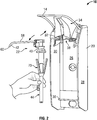
- Figure 1 illustrates a first embodiment of a fluid dispenser 10 adapted to be secured to a wall (not shown), and configured for manual activation as by a user using one hand 12 to urge a lever 14 downwardly so as to dispense fluid 16 onto the user's other hand 18.
- the fluid dispenser 10 is similar to that disclosed in U.S. Patent No. 7,748,573 to Ophardt et al., issued July 6, 2010 which is incorporated herein by reference.
- the fluid dispenser 10 includes a housing 20, a pump assembly 22, and a fluid reservoir 24.
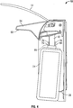
- the housing 20 is best shown in Figure 2 as having a back plate 26, spaced side walls 28 and 30, and an upper plate 32 defining an interior space therebetween sized for receiving the fluid reservoir 24 therein.
- a nozzle shield 34 is moveably coupled to the upper plate 32 to permit movement between a raised open position as shown in Figure 2 , wherein the pump assembly 22 can be inserted or removed from the housing 20, and a closed position as shown in Figure 1 .
- the upper plate 32 defines a central slot 38 adapted for removably coupling with a collar region 40 of the pump assembly 22.
- a support member 36 is attached to the back wall 26, for supporting the fluid reservoir 24 when held within the housing 20.
- the pump assembly 22 is best shown in Figure 2 as including a pump 42 and a dip tube 44.
- the pump assembly 22 is adapted to be removably coupled to the upper plate 32 for dispensing fluid from the fluid reservoir 24.
- the internal structure of the pump 42 is best shown in Figure 9 .
- the pump 42 includes a piston chamber forming body 46 and a piston forming element 48.
- the piston chamber forming body 46 is fixed to the housing 20 against movement through the coupling of the collar region 40 to the upper plate 32.
- the piston chamber forming body 46 carries and defines a piston chamber 50 and a dip tube coupling element 52 coaxially about a vertical axis 98.
- the piston forming element 48 is mounted to the piston chamber forming body 46 for relative vertical movement, with a piston 54 of the piston forming element 48 coaxially slidable within piston chamber 50.
- the piston 54 is biased upwardly by spring 56 disposed within the piston chamber 50 between the piston chamber 50 and the piston 54. Depression of the lever 14 moves the piston forming element 48 downwardly relative to the piston chamber forming body 46 against the bias of the spring 56.
- the piston forming element 48 includes a hollow spout tube 58 that extends from the piston 54 to a pump outlet 60.
- the piston 54 sits snuggly within the piston chamber 50, and is provided with a one way outlet duckbill valve 62 which permits fluid to flow upwardly into the piston 54 from the piston chamber 50, and prevents fluid from flowing out of the piston 54 into the piston chamber 50.
- the piston chamber 50 defines a cylindrical cavity within which the piston 54 is reciprocally coaxially slidable between a retracted position and an extended position to discharge fluid from the reservoir 24 out the pump outlet 60.
- a one-way inlet duckbill valve 64 sits between the piston chamber 50 and the dip tube coupling element 52, and permits fluid to flow upwardly into the piston chamber 50 from the dip tube coupling element 52, and prevents fluid from flowing out of the piston chamber 50 into the dip tube coupling element 52.
- a liquid compartment 51 is defined within the piston chamber 50 between the lower end of piston 54 carrying the one-way outlet duckbill valve 62 and the lower end of the piston chamber 50 carrying the one-way inlet duckbill valve 64.
- the volume of the liquid compartment 51 varies as the piston 54 moves between the retracted position and the extended position.
- the dip tube coupling element 52 is adapted for coupling to the dip tube 44, to place the pump 42 in fluid communication with the dip tube 44.
- the dip tube coupling element 52 is formed as a hollow tube extending downwardly from the piston chamber 50, and sized to fit in a sealed, friction fixed engagement within an outlet end 68 of the dip tube 44 such that friction holds the dip tube coupling element 52 and the dip tube 44 together in a coupled state against disengagement.
- the dip tube 44 is formed as an elongated hollow tube that extends downwardly along a longitudinal axis 98 from the outlet end 68 to an inlet end 66 positioned toward the bottom of the fluid reservoir 24 for drawing fluid 16 therefrom.
- the pump assembly 22 When in the pumping configuration shown in Figures 5 and 9 , with the pump outlet 60 external to the reservoir 24 and the inlet end 66 of the dip tube 44 in communication with fluid 16 in the reservoir 24, the pump assembly 22 is operated in a retraction stroke by depressing the lever 14, which causes the piston 54 to slide downwardly from the extended position toward the retracted position within the piston chamber 50. The movement of the piston 54 towards the retracted position reduces the volume of the liquid compartment 51, pressurizing the fluid 16 in the liquid compartment 51, forcing the fluid 16 upwards through the duckbill valve 62 through the hollow spout tube 58 and out the pump outlet 60.
- the pump assembly 22 and the fluid reservoir 24 are intended to be disposed of and replaced once the fluid 16 contained within the fluid reservoir 24 has been depleted.
- a locking member 70 is provided which is best shown in Figures 2 and 3 .
- the locking member 70 is coupled to the dip tube 44.
- the locking member 70 includes an annular ring 72 which is fixed to and surrounds the dip tube 44.
- Two elongated fingers 74 and 76 extend from the annular ring 72 from a lower proximal first end 78 to an upper distal second end 80.
- the upper distal second end 80 is provided with an upwardly directed stop surface 82.
- Each finger 74 and 76 extends radially outwardly as they extend axially upwardly such that the upper distal second end 80 is a greater radial distance from the dip tube 44 than the lower proximal first end 78.
- the fluid reservoir 24 is a hollow thin walled container formed with a circumferential side wall, closed at a lower end by a bottom wall and at an upper end by a top wall 23.
- the top wall 23 has an upwardly directed reservoir opening 86 at an upper end of an upwardly extending cylindrical neck 25 disposed about a vertical reservoir axis.
- the cylindrical neck 25 is supported and merges at its lower end into a radially outwardly extending top wall flange 29 generally normal to the reservoir axis which extends radially outwardly from the neck 25 to merge with a cylindrical downwardly extending annular wall 27 whose lower end merges outwardly and downwardly into the side wall.
- the interior surface of the top wall flange 29 provides an axially inwardly, that is, downwardly directed stopping shoulder 84.
- the stopping shoulder 84 is an inwardly, downwardly facing flat surface that surrounds the reservoir opening 86 within the reservoir 24.
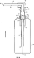
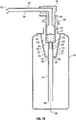
- the locking member 70 is coupled to the dip tube 44 such that as the dip tube 44 is inserted through the opening 86 of the fluid reservoir 24 into the fluid reservoir 24, the locking member 70 is also inserted through the opening 86 of the fluid reservoir 24 into the fluid reservoir 24 in a manner as shown by the sequence illustrated in succession in respect of the entire dispenser 10 by Figures 3 , 4 and 5 and also shown in cross-section with reference to the pump assembly 22 and reservoir 24 in Figures 7 , 8 and 9 .
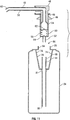
- Figures 9 and 10 show conditions when the pump assembly 22 is fixed to the housing 20 against axial movement and the pump assembly 22 is coupled to the dip tube 44 with the dip tube 44 and the locking member 70 is within the reservoir 24.
- Figures 5 and 9 illustrate a pumping configuration in which the reservoir 24 is supported on the support member 36 of the housing 20.
- the dip tube 44 is provided with a radially outwardly extending annular boss 81 carrying a catch shoulder 88 which extends radially outward from the dip tube 44 and is directed axially upwardly or outwardly toward the outlet end 68 of the dip tube 44, in opposition to an axially downwardly or inwardly directed catching shoulder 90 of the annular ring 72. Engagement of the catch shoulder 88 with the catching shoulder 90 prevents the dip tube 44 from sliding through the annular ring 72 and out the reservoir opening 86.
- the dip tube coupling element 52 and the dip tube 44 are held together by friction, and are configured to uncouple upon application of a sufficient force pulling the dip tube 44 axially downwardly away from the pump 42.
- the degree of force required is selected to be less than the force that would be required to fracture the locking member 70, or to otherwise detach the locking member 70 from the dip tube 44. This ensures that any attempt to forcibly detach the pump 42 from the reservoir 24 will result in the uncoupling of the dip tube 44 from the pump 42, as shown in Figures 6 and 11 . With the dip tube 44 removed from the pump 42 as seen in Figures 6 and 11 , the pump 42 can no longer be used to pump fluid 16 from a reservoir 24.
- the dip tube 44 is required to place the pump 42 in communication with fluid 16 contained within a fluid reservoir 24.
- the uncoupling of the pump 42 from the dip tube 44 prevents the pump assembly 22 from being reused.
- the locking member 70 is adapted to permit the dip tube 44 to be inserted through the reservoir opening 86 into the reservoir 24 while the locking member 70 is coupled to the dip tube 44.
- the fingers 74 and 76 are resiliently deformable having an inherent bias to assume an unbiased condition as seen in Figures 2 , 3 , 6 , 7 , 9 , 10 and 11 . When the fingers 74 and 76 are deflected from their unbiased condition their inherent bias biases them to return to the unbiased condition.
- Each of the fingers 74 and 76 have a radially outwardly directed cam surface 93 that angles radially outwardly as it extends axially upwardly.
- Each cam surface 93 is adapted to engage with a radially inwardly directed camming surface 94 formed by the lip of the reservoir opening 86 and the interior of the cylindrical neck 25 as seen in Figure 7 , so as to deflect the fingers 74 and 76 radially inward toward the dip tube 44 when the dip tube 44 is being inserted by the inlet end 66 first into the reservoir 24 through the reservoir opening 86 as seen in Figure 8 .
- This inward deflection of the fingers 74 and 76 permits the locking member 70 to pass through the reservoir opening 86 and into the reservoir 24, as best shown in Figures 4 and 8 .
- the fingers 74 and 76 deflect under their inherent bias to move radially outward from the dip tube 44 to their inherent unbiased condition assuming the locking configuration as shown in Figure 9 and 10 , wherein the stop surfaces 82 of the fingers 74 and 76 are positioned in opposition to the stopping shoulder 84, for locking the dip tube 44 within the reservoir 24. Since the stop surfaces 82 of the fingers 74 and 76 are spaced a distance greater than a diameter of the reservoir opening 86, the dip tube 44 is prevented from being extracted from the reservoir 24 through the reservoir opening 86.
- the relative orientations of the fingers 74 and 76 and the stopping shoulder 84, with the fingers 74 and 76 extending radially outwardly as they extend axially upwardly toward the outlet end 68 of the dip tube 44, and with the stopping shoulder 84 forming a flat, inwardly facing surface, are selected so that when the reservoir 24 is drawn axially away from the pump 42, the engagement of the fingers 74 and 76 with the stopping shoulder 84 urges the stop surfaces 82 of the fingers 74 and 76 to slide radially outwardly away from the reservoir opening 86 and thus to resist movement of the fingers 74 and 76 radially inward toward the dip tube 44.
- the relative size and location of the reservoir opening 86, the pump 42, the dip tube 44, and the stopping shoulder 84 prevent manual access to the locking member 70 as, for example, to prevent a user from manually deflecting the fingers 74 and 76 within the reservoir 24 to extract the dip tube 44.
- the outlet end 68 of the dip tube 44 does not extend outwardly beyond the reservoir opening 86, as can be advantageous to prevent a user from engaging the dip tube 44 through the reservoir opening 86 or attempting to couple the dip tube 44 with the pump 42.
- annular space 91 between the radially inwardly directed surface of the cylindrical neck 25 of the reservoir 24 and the radially outwardly directed surface of the piston chamber forming body 46 is sufficient to permit the fingers 74 and 76 when deflected to pass axially therethrough.
- the relative diameters of the cylindrical neck 25 of the reservoir 24 and the radially outwardly directed surface of the piston chamber forming body 46 are selected to minimize the annular space 91 yet permit the fingers 74 and 76 to pass there through.
- the relative size and configuration of the dip tube 44, the locking member 70 and the reservoir 24 and its reservoir opening 86, cylindrical neck 25, and stopping shoulder 84 are preferably selected to the prevent manual access to the dip tube 44 or to the locking member 70 as, for example, to prevent a user from manually deflecting the fingers 74 and 76 within the reservoir 24 to extract the dip tube 44.
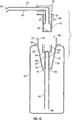
- FIG. 12 and 13 A second embodiment of the invention is illustrated in Figures 12 and 13 , wherein like numerals are used to represent like components.
- the embodiment of the invention shown in Figures 12 and 13 is identical to the first embodiment shown in Figure 10 but for five exceptions.
- a first exception is that the dip tube 44 and the dip tube coupling element 52 are fixed together against disengagement.
- the pump 42 is provided with a frangible or weakened region 96 which is configured to fracture when the pump 42 is pulled axially away from the reservoir 24.
- the piston chamber 50 has an annular weakened region 96 that extends around the entire circumference of the piston chamber 50.
- the weakened region 96 is configured to fracture when the pump 42 is pulled axially away from the reservoir 24 from the condition of Figure 12 to the condition of Figure 13 .
- each foot 99 provides for enhanced engagement with the stopping shoulder 84 to prevent relative axial movement and engagement between a radially outwardly directed surface 97 of the foot 99 with a radially inwardly directed surface of the cylindrical downwardly extending annular wall 27 of the reservoir 24 to limit radial outward movement of the foot 99.
- a fourth exception is that the diameter of the reservoir opening 86 and the neck 25 of the reservoir 24 is increased to facilitate the modified fingers 74 and 76, with each having a foot 99, to be inserted into the reservoir 24.
- a fifth exception is that the radially outwardly extending annular boss 81 on the dip tube 44 is enlarged to extend farther outwardly radially from the dip tube 44 and to carry as a radially outwardly directed surface an angled annular cam surface 83 that extends axially upwardly as it extends radially outwardly.
- the annular cam surface 83 merges upwardly with the cam surfaces 93 of the fingers 74 and 76.
- the annular cam surface 83 serves to assist during insertion of the dip tube 44 through the reservoir opening 86 in locating the dip tube 44 centered within the reservoir opening 86 by engaging the radially inwardly directed camming surface 94 formed by the lip of the reservoir opening 86 and the interior of the cylindrical neck 25.
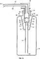
- FIG. 14 A third embodiment of the invention is illustrated in Figure 14 , wherein like reference numerals are used to denote like components.
- the embodiment shown in Figure 14 is identical to the embodiment shown in Figures 1 to 11 , with the exception that the duckbill valve 64 is carried on the outlet end 68 of the dip tube 44 rather than on the piston chamber forming body 46.
- the duckbill valve 64 is also removed, rendering the pump 42 inoperative upon uncoupling of the dip tube 44 from the pump 42.
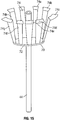
- Figure 15 depicts a dip tube 44 and locking member 70 in accordance with a fourth embodiment of the invention, wherein like reference numerals are used to represent like components.
- the dip tube 44 and locking member 70 as shown in Figure 15 are identical to those shown in Figure 12 , with the exception that the locking member 70 is provided with more than two fingers, namely, with a plurality of fingers 74a-74i spaced circumferentially from each other about the annular ring 72. This construction of the locking member 70 helps to ensure that the reservoir 24 is not reused.
- the plurality of fingers 74a-74i extend radially outward from the dip tube 44 in all directions, they act to substantially block the reservoir opening 86, for example, serving to impede any attempts to refill the reservoir 24 with fluid, or to insert a further dip tube 44 into the reservoir 24.
- the locking member 70 is furthermore configured to continue blocking the reservoir opening 86 both while the pump 42 is coupled to the reservoir 24 and after the pump 42 is uncoupled from the dip tube 44.
- FIG. 16 A fifth embodiment of the invention is shown in Figure 16 , wherein like numerals are used to denote like components.
- the embodiment shown in Figure 16 is most similar to the embodiment shown in Figure 14 , however, in Figure 16 , the reservoir 24 and pump assembly 22 are configured to dispense fluid 16 while in an inverted orientation as shown in Figure 16 , with the reservoir opening 86 facing downwards.
- the piston chamber forming body 46 is adapted to sealingly engage with the reservoir opening 86 so as to prevent the fluid 16 from leaking out of the reservoir 24 while inverted.
- the neck 25 of the reservoir 24 is threaded, and the piston chamber forming body 46 is provided with a threaded sleeve 104 for sealingly engaging with the threaded neck 25.
- the pump 42 is configured such that the pump outlet 60 extends directly downward from the piston 54, for dispensing the fluid 16 downwardly while in the inverted orientation. Since the reservoir 24 is inverted, the fluid 16 pools around the pump 42, and a shortened feed tube replaces the dip tube of the first embodiment to place the pump 42 in communication with the fluid 16. Accordingly, the pump assembly 22 is not provided with a dip tube.
- the body 46 has a cylindrical tube 106 open at an inner axial end.
- the locking member 70 is shown as integrally including a cap portion 108 and the fingers 74 and 76.
- the cap portion 108 has a cylindrical wall 109 forming the feed tube and an end wall 110 carrying the one-way inlet duckbill valve 64.
- the fingers 74 and 76 extend from their proximal first ends 78 secured to the cylindrical tube 106 radially outwardly and axially outwardly to their second ends 80.
- the cylindrical wall 109 of the feed tube of the cap portion 108 is disposed coaxially outwardly of the tube 106 in frictional engagement. If, after the threaded sleeve 104 has been disengaged from the threaded neck 25, the body 46 is drawn axially outwardly from the reservoir 24, the fingers 74 and 76 engage with the stopping shoulder 84 of the reservoir 24. When sufficient forces are applied to the body 46, the forces will overcome the frictional engagement of the cap portion 108 of the locking member 70 and the tube 106, disengaging the locking member 70 from the tube 106 and, in so doing, removing the inlet duckbill valve 64 from the tube 106 rendering the pump assembly as remaining on the body 46 inoperative.
- the fingers 74 and 76 of locking member 70 in Figure 16 are shown slightly shorter in axial length than in the other embodiments having a dip tube 44 however, and the locking member 70 and its fingers 74 and 76 function similarly as in the other embodiments to prevent the pump 42 from being removed from the reservoir opening 86 through engagement of the stop surface 82 of the locking member 70 with the stopping shoulder 84 of the reservoir 24.
- the fluid dispenser 10 of the present invention is used to dispense a hand cleaner such as hand soap or hand sanitizer. It is to be appreciated, however, that the fluid dispenser 10 could alternatively be used to dispense any desired fluid 16, such as hand cream, hair gel, toothpaste, food products or the like.
- the pump assembly 22 and reservoir 24 are intended to be disposed of and replaced after each use.
- the pump assembly 22 and reservoir 24 are formed from relatively inexpensive materials, such as plastics, although any suitable materials could be used. Since the pump assembly 22 and the reservoir 24 are intended to be replaced after use to dispense the fluid within the reservoir 24 but once, it is not necessary for the pump assembly 22 or the reservoir 24 to be constructed so as to withstand long periods of wear, or cleaning procedures such as autoclaving.
- any locking member 70 construction that functions to prevent extraction of the dip tube 44 could be used, and not just the particular construction that has been illustrated.
- the locking member 70 may, for example, be integrally formed with the dip tube 44.
- Figures 1 to 15 illustrate a dispenser 10 in which the pump assembly 22 is first coupled to the housing 20, as seen in Figure 3 and the reservoir 24, then coupled to the pump assembly 22 and the housing 20.
- the reservoir opening 86 of the reservoir 24 is not sealably engaged to the pump assembly 22.
- the pump assembly 22 is coupled to the reservoir 24 as in the condition shown in Figure 9 as well as Figure 5 .
- With the pump assembly 22 coupled to the reservoir 24 as in the condition shown in Figure 9 they, in effect, together form a removable cartridge 100 which can be removed from the dispenser 10 by pivoting the nozzle shield 34 to a raised position and sliding the cartridge 100, comprising both the pump assembly 22 and the reservoir 24 forwardly.
- such a cartridge 100 comprising the pump assembly 22 coupled to the reservoir 24 can be inserted into the dispenser 10 while the nozzle shield 34 is in a raised position.
- the cartridge 100 comprising the pump assembly 22 is coupled to the reservoir 24 as in the condition shown in Figure 9 may be modified to provide a secondary mechanism for coupling the reservoir 24 to the pump assembly 22, such as a threaded collar carried on the piston chamber forming body 46 which removably engages with a thread on the neck 25 of the reservoir 24. Nevertheless, in such a modification while the secondary mechanism is disengaged, the locking member 70 will continue to serve the function of preventing removal of the dip tube 44 and locking member 70 from within the reservoir 24.
- While the preferred embodiments have been illustrated as employing one particular form of piston pump 42, it is to be appreciated that many other possible types of pumps 42 could be used instead.
- the invention could be used in association with the pumps 42 described and illustrated in United States Patent No. 5,489,044 to Ophardt ; United States Patent No. 7,984,825 to Ophardt et al. ; and United States Patent No. 8,684,236 to Ophardt , which are incorporated herein by reference.
Landscapes
- Health & Medical Sciences (AREA)
- Public Health (AREA)
- Containers And Packaging Bodies Having A Special Means To Remove Contents (AREA)
Priority Applications (1)
| Application Number | Priority Date | Filing Date | Title |
|---|---|---|---|
| EP15164004.2A EP3081312B1 (fr) | 2015-04-17 | 2015-04-17 | Distributeur de fluide avec pompe à usage unique |
Applications Claiming Priority (1)
| Application Number | Priority Date | Filing Date | Title |
|---|---|---|---|
| EP15164004.2A EP3081312B1 (fr) | 2015-04-17 | 2015-04-17 | Distributeur de fluide avec pompe à usage unique |
Publications (2)
| Publication Number | Publication Date |
|---|---|
| EP3081312A1 true EP3081312A1 (fr) | 2016-10-19 |
| EP3081312B1 EP3081312B1 (fr) | 2021-03-17 |
Family
ID=52997279
Family Applications (1)
| Application Number | Title | Priority Date | Filing Date |
|---|---|---|---|
| EP15164004.2A Active EP3081312B1 (fr) | 2015-04-17 | 2015-04-17 | Distributeur de fluide avec pompe à usage unique |
Country Status (1)
| Country | Link |
|---|---|
| EP (1) | EP3081312B1 (fr) |
Cited By (4)
| Publication number | Priority date | Publication date | Assignee | Title |
|---|---|---|---|---|
| WO2019133317A1 (fr) * | 2017-12-29 | 2019-07-04 | Colgate-Palmolive Company | Système distributeur |
| EP3650128A1 (fr) | 2018-11-08 | 2020-05-13 | OP-Hygiene IP GmbH | Tube plongeur frangible |
| JP2023162824A (ja) * | 2022-04-27 | 2023-11-09 | 株式会社吉野工業所 | 吐出器 |
| EP4495023A1 (fr) | 2023-07-21 | 2025-01-22 | OP-Hygiene IP GmbH | Distributeur de fluide avec élément d'étanchéité frangible |
Families Citing this family (2)
| Publication number | Priority date | Publication date | Assignee | Title |
|---|---|---|---|---|
| WO2023091332A1 (fr) * | 2021-11-17 | 2023-05-25 | Gojo Industries, Inc. | Distributeur de désinfectant de dessus de table à usage unique doté d'un tube plongeur auto-détachable |
| WO2023200629A1 (fr) * | 2022-04-14 | 2023-10-19 | Gojo Industries, Inc. | Distributeurs de table avec mécanismes anti-remplissage et anti-effraction |
Citations (7)
| Publication number | Priority date | Publication date | Assignee | Title |
|---|---|---|---|---|
| US3129854A (en) * | 1961-08-21 | 1964-04-21 | Drackett Co | Dispensing device |
| US5489044A (en) | 1991-05-20 | 1996-02-06 | Hygiene-Technik Inc. | Method of preparing replaceable liquid soap reservoir |
| DE102007018349B3 (de) * | 2007-04-16 | 2008-04-30 | Gaurav Malhotra | Trinkhilfe |
| US20080164286A1 (en) * | 2004-12-23 | 2008-07-10 | Valois Sas | Fluid Product Dispenser |
| US7748573B2 (en) | 2006-03-08 | 2010-07-06 | Gotohti.Com | Removable nozzle shield for fluid dispenser |
| US7984825B2 (en) | 2007-06-18 | 2011-07-26 | Gotohti.Com Inc. | Optically keyed dispenser |
| US8684236B2 (en) | 2009-02-27 | 2014-04-01 | Gotohti.Com Inc. | Manual fluid dispenser with piezoelectric generator |
-
2015
- 2015-04-17 EP EP15164004.2A patent/EP3081312B1/fr active Active
Patent Citations (7)
| Publication number | Priority date | Publication date | Assignee | Title |
|---|---|---|---|---|
| US3129854A (en) * | 1961-08-21 | 1964-04-21 | Drackett Co | Dispensing device |
| US5489044A (en) | 1991-05-20 | 1996-02-06 | Hygiene-Technik Inc. | Method of preparing replaceable liquid soap reservoir |
| US20080164286A1 (en) * | 2004-12-23 | 2008-07-10 | Valois Sas | Fluid Product Dispenser |
| US7748573B2 (en) | 2006-03-08 | 2010-07-06 | Gotohti.Com | Removable nozzle shield for fluid dispenser |
| DE102007018349B3 (de) * | 2007-04-16 | 2008-04-30 | Gaurav Malhotra | Trinkhilfe |
| US7984825B2 (en) | 2007-06-18 | 2011-07-26 | Gotohti.Com Inc. | Optically keyed dispenser |
| US8684236B2 (en) | 2009-02-27 | 2014-04-01 | Gotohti.Com Inc. | Manual fluid dispenser with piezoelectric generator |
Cited By (14)
| Publication number | Priority date | Publication date | Assignee | Title |
|---|---|---|---|---|
| US11033920B2 (en) | 2017-12-29 | 2021-06-15 | Colgate-Palmolive Company | Dispenser system |
| US12168240B2 (en) | 2017-12-29 | 2024-12-17 | Colgate-Palmolive Company | Dispenser system |
| AU2018397599B2 (en) * | 2017-12-29 | 2021-09-09 | Colgate-Palmolive Company | Dispenser system |
| US10675646B2 (en) | 2017-12-29 | 2020-06-09 | Colgate-Palmolive Company | Dispenser system |
| CN111526767A (zh) * | 2017-12-29 | 2020-08-11 | 高露洁-棕榄公司 | 分配器系统 |
| WO2019133317A1 (fr) * | 2017-12-29 | 2019-07-04 | Colgate-Palmolive Company | Système distributeur |
| WO2019133464A1 (fr) * | 2017-12-29 | 2019-07-04 | Colgate-Palmolive Company | Système distributeur |
| EP4019147A1 (fr) | 2018-11-08 | 2022-06-29 | OP-Hygiene IP GmbH | Tube plongeur frangible |
| US10974267B2 (en) | 2018-11-08 | 2021-04-13 | Op-Hygiene Ip Gmbh | Frangible dip tube |
| EP3650128A1 (fr) | 2018-11-08 | 2020-05-13 | OP-Hygiene IP GmbH | Tube plongeur frangible |
| JP7720811B2 (ja) | 2022-04-27 | 2025-08-08 | 株式会社吉野工業所 | 吐出器 |
| JP2023162824A (ja) * | 2022-04-27 | 2023-11-09 | 株式会社吉野工業所 | 吐出器 |
| EP4495023A1 (fr) | 2023-07-21 | 2025-01-22 | OP-Hygiene IP GmbH | Distributeur de fluide avec élément d'étanchéité frangible |
| US12605015B2 (en) | 2023-07-21 | 2026-04-21 | Op-Hygiene Ip Gmbh | Fluid dispenser with frangible sealing element |
Also Published As
| Publication number | Publication date |
|---|---|
| EP3081312B1 (fr) | 2021-03-17 |
Similar Documents
| Publication | Publication Date | Title |
|---|---|---|
| EP3650128B1 (fr) | Tube plongeur frangible | |
| EP3081312B1 (fr) | Distributeur de fluide avec pompe à usage unique | |
| CN105407947B (zh) | 流体产品或粉末产品的分配装置 | |
| EP0836824B1 (fr) | Méthode d'évacuation | |
| EP2259982B1 (fr) | Système de distribution jetable comprenant un conteneur pliable, distributeur et procédé de distribution de liquide à partir de ce système de distribution | |
| US5975360A (en) | Capped piston pump | |
| US6082593A (en) | Low maintenance cosmetic dispenser with a slideable nozzle hood | |
| EP2641521B1 (fr) | Pompe de précharge adaptative | |
| US9062667B2 (en) | Variable volume bore piston pump | |
| US7959037B2 (en) | Severable piston pump | |
| EP3298939A1 (fr) | Pompe pour système de distribution sous comptoir | |
| CN105407946A (zh) | 流体产品或粉末产品的分配装置 | |
| WO2018236573A1 (fr) | Distributeur à réservoirs multiples | |
| US20230149964A1 (en) | Single use table top sanitizer dispensers and self-detaching dip tubes for same | |
| US10584697B2 (en) | Piston pump arrangement automatically disabling in absence of inlet liquid | |
| AU709023B2 (en) | Cosmetic dispenser | |
| EP3845104B1 (fr) | Pompe à tige stationnaire de sortie | |
| CA2507914A1 (fr) | Pompe a piston frangible |
Legal Events
| Date | Code | Title | Description |
|---|---|---|---|
| PUAI | Public reference made under article 153(3) epc to a published international application that has entered the european phase |
Free format text: ORIGINAL CODE: 0009012 |
|
| AK | Designated contracting states |
Kind code of ref document: A1 Designated state(s): AL AT BE BG CH CY CZ DE DK EE ES FI FR GB GR HR HU IE IS IT LI LT LU LV MC MK MT NL NO PL PT RO RS SE SI SK SM TR |
|
| AX | Request for extension of the european patent |
Extension state: BA ME |
|
| STAA | Information on the status of an ep patent application or granted ep patent |
Free format text: STATUS: REQUEST FOR EXAMINATION WAS MADE |
|
| RBV | Designated contracting states (corrected) |
Designated state(s): AL AT BE BG CH CY CZ DE DK EE ES FI FR GB GR HR HU IE IS IT LI LT LU LV MC MK MT NL NO PL PT RO RS SE SI SK SM TR |
|
| 17P | Request for examination filed |
Effective date: 20170419 |
|
| STAA | Information on the status of an ep patent application or granted ep patent |
Free format text: STATUS: EXAMINATION IS IN PROGRESS |
|
| 17Q | First examination report despatched |
Effective date: 20190807 |
|
| RIC1 | Information provided on ipc code assigned before grant |
Ipc: B05B 11/00 20060101AFI20200124BHEP Ipc: A47K 5/12 20060101ALI20200124BHEP Ipc: B05B 15/30 20180101ALN20200124BHEP |
|
| GRAP | Despatch of communication of intention to grant a patent |
Free format text: ORIGINAL CODE: EPIDOSNIGR1 |
|
| STAA | Information on the status of an ep patent application or granted ep patent |
Free format text: STATUS: GRANT OF PATENT IS INTENDED |
|
| INTG | Intention to grant announced |
Effective date: 20200403 |
|
| GRAJ | Information related to disapproval of communication of intention to grant by the applicant or resumption of examination proceedings by the epo deleted |
Free format text: ORIGINAL CODE: EPIDOSDIGR1 |
|
| STAA | Information on the status of an ep patent application or granted ep patent |
Free format text: STATUS: EXAMINATION IS IN PROGRESS |
|
| INTC | Intention to grant announced (deleted) | ||
| RIC1 | Information provided on ipc code assigned before grant |
Ipc: B05B 15/30 20180101ALN20200730BHEP Ipc: A47K 5/12 20060101ALI20200730BHEP Ipc: B05B 11/00 20060101AFI20200730BHEP |
|
| GRAP | Despatch of communication of intention to grant a patent |
Free format text: ORIGINAL CODE: EPIDOSNIGR1 |
|
| STAA | Information on the status of an ep patent application or granted ep patent |
Free format text: STATUS: GRANT OF PATENT IS INTENDED |
|
| INTG | Intention to grant announced |
Effective date: 20200930 |
|
| GRAS | Grant fee paid |
Free format text: ORIGINAL CODE: EPIDOSNIGR3 |
|
| GRAA | (expected) grant |
Free format text: ORIGINAL CODE: 0009210 |
|
| STAA | Information on the status of an ep patent application or granted ep patent |
Free format text: STATUS: THE PATENT HAS BEEN GRANTED |
|
| AK | Designated contracting states |
Kind code of ref document: B1 Designated state(s): AL AT BE BG CH CY CZ DE DK EE ES FI FR GB GR HR HU IE IS IT LI LT LU LV MC MK MT NL NO PL PT RO RS SE SI SK SM TR |
|
| REG | Reference to a national code |
Ref country code: GB Ref legal event code: FG4D |
|
| REG | Reference to a national code |
Ref country code: CH Ref legal event code: EP |
|
| REG | Reference to a national code |
Ref country code: DE Ref legal event code: R096 Ref document number: 602015066885 Country of ref document: DE |
|
| REG | Reference to a national code |
Ref country code: IE Ref legal event code: FG4D |
|
| REG | Reference to a national code |
Ref country code: AT Ref legal event code: REF Ref document number: 1371754 Country of ref document: AT Kind code of ref document: T Effective date: 20210415 |
|
| REG | Reference to a national code |
Ref country code: NL Ref legal event code: FP |
|
| REG | Reference to a national code |
Ref country code: LT Ref legal event code: MG9D |
|
| PG25 | Lapsed in a contracting state [announced via postgrant information from national office to epo] |
Ref country code: NO Free format text: LAPSE BECAUSE OF FAILURE TO SUBMIT A TRANSLATION OF THE DESCRIPTION OR TO PAY THE FEE WITHIN THE PRESCRIBED TIME-LIMIT Effective date: 20210617 Ref country code: BG Free format text: LAPSE BECAUSE OF FAILURE TO SUBMIT A TRANSLATION OF THE DESCRIPTION OR TO PAY THE FEE WITHIN THE PRESCRIBED TIME-LIMIT Effective date: 20210617 Ref country code: GR Free format text: LAPSE BECAUSE OF FAILURE TO SUBMIT A TRANSLATION OF THE DESCRIPTION OR TO PAY THE FEE WITHIN THE PRESCRIBED TIME-LIMIT Effective date: 20210618 Ref country code: HR Free format text: LAPSE BECAUSE OF FAILURE TO SUBMIT A TRANSLATION OF THE DESCRIPTION OR TO PAY THE FEE WITHIN THE PRESCRIBED TIME-LIMIT Effective date: 20210317 Ref country code: FI Free format text: LAPSE BECAUSE OF FAILURE TO SUBMIT A TRANSLATION OF THE DESCRIPTION OR TO PAY THE FEE WITHIN THE PRESCRIBED TIME-LIMIT Effective date: 20210317 |
|
| REG | Reference to a national code |
Ref country code: AT Ref legal event code: MK05 Ref document number: 1371754 Country of ref document: AT Kind code of ref document: T Effective date: 20210317 |
|
| PG25 | Lapsed in a contracting state [announced via postgrant information from national office to epo] |
Ref country code: SE Free format text: LAPSE BECAUSE OF FAILURE TO SUBMIT A TRANSLATION OF THE DESCRIPTION OR TO PAY THE FEE WITHIN THE PRESCRIBED TIME-LIMIT Effective date: 20210317 Ref country code: RS Free format text: LAPSE BECAUSE OF FAILURE TO SUBMIT A TRANSLATION OF THE DESCRIPTION OR TO PAY THE FEE WITHIN THE PRESCRIBED TIME-LIMIT Effective date: 20210317 Ref country code: LV Free format text: LAPSE BECAUSE OF FAILURE TO SUBMIT A TRANSLATION OF THE DESCRIPTION OR TO PAY THE FEE WITHIN THE PRESCRIBED TIME-LIMIT Effective date: 20210317 |
|
| PG25 | Lapsed in a contracting state [announced via postgrant information from national office to epo] |
Ref country code: LT Free format text: LAPSE BECAUSE OF FAILURE TO SUBMIT A TRANSLATION OF THE DESCRIPTION OR TO PAY THE FEE WITHIN THE PRESCRIBED TIME-LIMIT Effective date: 20210317 Ref country code: CZ Free format text: LAPSE BECAUSE OF FAILURE TO SUBMIT A TRANSLATION OF THE DESCRIPTION OR TO PAY THE FEE WITHIN THE PRESCRIBED TIME-LIMIT Effective date: 20210317 Ref country code: EE Free format text: LAPSE BECAUSE OF FAILURE TO SUBMIT A TRANSLATION OF THE DESCRIPTION OR TO PAY THE FEE WITHIN THE PRESCRIBED TIME-LIMIT Effective date: 20210317 Ref country code: AT Free format text: LAPSE BECAUSE OF FAILURE TO SUBMIT A TRANSLATION OF THE DESCRIPTION OR TO PAY THE FEE WITHIN THE PRESCRIBED TIME-LIMIT Effective date: 20210317 Ref country code: SM Free format text: LAPSE BECAUSE OF FAILURE TO SUBMIT A TRANSLATION OF THE DESCRIPTION OR TO PAY THE FEE WITHIN THE PRESCRIBED TIME-LIMIT Effective date: 20210317 |
|
| PG25 | Lapsed in a contracting state [announced via postgrant information from national office to epo] |
Ref country code: IS Free format text: LAPSE BECAUSE OF FAILURE TO SUBMIT A TRANSLATION OF THE DESCRIPTION OR TO PAY THE FEE WITHIN THE PRESCRIBED TIME-LIMIT Effective date: 20210717 Ref country code: RO Free format text: LAPSE BECAUSE OF FAILURE TO SUBMIT A TRANSLATION OF THE DESCRIPTION OR TO PAY THE FEE WITHIN THE PRESCRIBED TIME-LIMIT Effective date: 20210317 Ref country code: SK Free format text: LAPSE BECAUSE OF FAILURE TO SUBMIT A TRANSLATION OF THE DESCRIPTION OR TO PAY THE FEE WITHIN THE PRESCRIBED TIME-LIMIT Effective date: 20210317 Ref country code: ES Free format text: LAPSE BECAUSE OF FAILURE TO SUBMIT A TRANSLATION OF THE DESCRIPTION OR TO PAY THE FEE WITHIN THE PRESCRIBED TIME-LIMIT Effective date: 20210317 Ref country code: PT Free format text: LAPSE BECAUSE OF FAILURE TO SUBMIT A TRANSLATION OF THE DESCRIPTION OR TO PAY THE FEE WITHIN THE PRESCRIBED TIME-LIMIT Effective date: 20210719 Ref country code: PL Free format text: LAPSE BECAUSE OF FAILURE TO SUBMIT A TRANSLATION OF THE DESCRIPTION OR TO PAY THE FEE WITHIN THE PRESCRIBED TIME-LIMIT Effective date: 20210317 |
|
| REG | Reference to a national code |
Ref country code: DE Ref legal event code: R097 Ref document number: 602015066885 Country of ref document: DE |
|
| PG25 | Lapsed in a contracting state [announced via postgrant information from national office to epo] |
Ref country code: LU Free format text: LAPSE BECAUSE OF NON-PAYMENT OF DUE FEES Effective date: 20210417 |
|
| REG | Reference to a national code |
Ref country code: BE Ref legal event code: MM Effective date: 20210430 |
|
| PLBE | No opposition filed within time limit |
Free format text: ORIGINAL CODE: 0009261 |
|
| STAA | Information on the status of an ep patent application or granted ep patent |
Free format text: STATUS: NO OPPOSITION FILED WITHIN TIME LIMIT |
|
| PG25 | Lapsed in a contracting state [announced via postgrant information from national office to epo] |
Ref country code: DK Free format text: LAPSE BECAUSE OF FAILURE TO SUBMIT A TRANSLATION OF THE DESCRIPTION OR TO PAY THE FEE WITHIN THE PRESCRIBED TIME-LIMIT Effective date: 20210317 Ref country code: MC Free format text: LAPSE BECAUSE OF FAILURE TO SUBMIT A TRANSLATION OF THE DESCRIPTION OR TO PAY THE FEE WITHIN THE PRESCRIBED TIME-LIMIT Effective date: 20210317 Ref country code: LI Free format text: LAPSE BECAUSE OF NON-PAYMENT OF DUE FEES Effective date: 20210430 Ref country code: CH Free format text: LAPSE BECAUSE OF NON-PAYMENT OF DUE FEES Effective date: 20210430 Ref country code: AL Free format text: LAPSE BECAUSE OF FAILURE TO SUBMIT A TRANSLATION OF THE DESCRIPTION OR TO PAY THE FEE WITHIN THE PRESCRIBED TIME-LIMIT Effective date: 20210317 |
|
| 26N | No opposition filed |
Effective date: 20211220 |
|
| PG25 | Lapsed in a contracting state [announced via postgrant information from national office to epo] |
Ref country code: SI Free format text: LAPSE BECAUSE OF FAILURE TO SUBMIT A TRANSLATION OF THE DESCRIPTION OR TO PAY THE FEE WITHIN THE PRESCRIBED TIME-LIMIT Effective date: 20210317 |
|
| PG25 | Lapsed in a contracting state [announced via postgrant information from national office to epo] |
Ref country code: IT Free format text: LAPSE BECAUSE OF FAILURE TO SUBMIT A TRANSLATION OF THE DESCRIPTION OR TO PAY THE FEE WITHIN THE PRESCRIBED TIME-LIMIT Effective date: 20210317 Ref country code: IE Free format text: LAPSE BECAUSE OF NON-PAYMENT OF DUE FEES Effective date: 20210417 |
|
| PG25 | Lapsed in a contracting state [announced via postgrant information from national office to epo] |
Ref country code: IS Free format text: LAPSE BECAUSE OF FAILURE TO SUBMIT A TRANSLATION OF THE DESCRIPTION OR TO PAY THE FEE WITHIN THE PRESCRIBED TIME-LIMIT Effective date: 20210717 |
|
| PG25 | Lapsed in a contracting state [announced via postgrant information from national office to epo] |
Ref country code: BE Free format text: LAPSE BECAUSE OF NON-PAYMENT OF DUE FEES Effective date: 20210430 |
|
| PG25 | Lapsed in a contracting state [announced via postgrant information from national office to epo] |
Ref country code: HU Free format text: LAPSE BECAUSE OF FAILURE TO SUBMIT A TRANSLATION OF THE DESCRIPTION OR TO PAY THE FEE WITHIN THE PRESCRIBED TIME-LIMIT; INVALID AB INITIO Effective date: 20150417 |
|
| PG25 | Lapsed in a contracting state [announced via postgrant information from national office to epo] |
Ref country code: CY Free format text: LAPSE BECAUSE OF FAILURE TO SUBMIT A TRANSLATION OF THE DESCRIPTION OR TO PAY THE FEE WITHIN THE PRESCRIBED TIME-LIMIT Effective date: 20210317 |
|
| PG25 | Lapsed in a contracting state [announced via postgrant information from national office to epo] |
Ref country code: MK Free format text: LAPSE BECAUSE OF FAILURE TO SUBMIT A TRANSLATION OF THE DESCRIPTION OR TO PAY THE FEE WITHIN THE PRESCRIBED TIME-LIMIT Effective date: 20210317 |
|
| PG25 | Lapsed in a contracting state [announced via postgrant information from national office to epo] |
Ref country code: TR Free format text: LAPSE BECAUSE OF FAILURE TO SUBMIT A TRANSLATION OF THE DESCRIPTION OR TO PAY THE FEE WITHIN THE PRESCRIBED TIME-LIMIT Effective date: 20210317 |
|
| PG25 | Lapsed in a contracting state [announced via postgrant information from national office to epo] |
Ref country code: MT Free format text: LAPSE BECAUSE OF FAILURE TO SUBMIT A TRANSLATION OF THE DESCRIPTION OR TO PAY THE FEE WITHIN THE PRESCRIBED TIME-LIMIT Effective date: 20210317 |
|
| PGFP | Annual fee paid to national office [announced via postgrant information from national office to epo] |
Ref country code: NL Payment date: 20250426 Year of fee payment: 11 |
|
| PGFP | Annual fee paid to national office [announced via postgrant information from national office to epo] |
Ref country code: DE Payment date: 20250425 Year of fee payment: 11 |
|
| PGFP | Annual fee paid to national office [announced via postgrant information from national office to epo] |
Ref country code: GB Payment date: 20250426 Year of fee payment: 11 |
|
| PGFP | Annual fee paid to national office [announced via postgrant information from national office to epo] |
Ref country code: FR Payment date: 20250426 Year of fee payment: 11 |