EP3081341B1 - Ensemble d'outils pour une machine-outil portative - Google Patents
Ensemble d'outils pour une machine-outil portative Download PDFInfo
- Publication number
- EP3081341B1 EP3081341B1 EP16159670.5A EP16159670A EP3081341B1 EP 3081341 B1 EP3081341 B1 EP 3081341B1 EP 16159670 A EP16159670 A EP 16159670A EP 3081341 B1 EP3081341 B1 EP 3081341B1
- Authority
- EP
- European Patent Office
- Prior art keywords
- tool
- attachment
- housing
- spring
- receptacle
- Prior art date
- Legal status (The legal status is an assumption and is not a legal conclusion. Google has not performed a legal analysis and makes no representation as to the accuracy of the status listed.)
- Active
Links
Images



Classifications
-
- B—PERFORMING OPERATIONS; TRANSPORTING
- B25—HAND TOOLS; PORTABLE POWER-DRIVEN TOOLS; MANIPULATORS
- B25F—COMBINATION OR MULTI-PURPOSE TOOLS NOT OTHERWISE PROVIDED FOR; DETAILS OR COMPONENTS OF PORTABLE POWER-DRIVEN TOOLS NOT PARTICULARLY RELATED TO THE OPERATIONS PERFORMED AND NOT OTHERWISE PROVIDED FOR
- B25F3/00—Associations of tools for different working operations with one portable power-drive means; Adapters therefor
-
- B—PERFORMING OPERATIONS; TRANSPORTING
- B23—MACHINE TOOLS; METAL-WORKING NOT OTHERWISE PROVIDED FOR
- B23B—TURNING; BORING
- B23B45/00—Hand-held or like portable drilling machines, e.g. drill guns; Equipment therefor
- B23B45/003—Attachments
-
- B—PERFORMING OPERATIONS; TRANSPORTING
- B25—HAND TOOLS; PORTABLE POWER-DRIVEN TOOLS; MANIPULATORS
- B25B—TOOLS OR BENCH DEVICES NOT OTHERWISE PROVIDED FOR, FOR FASTENING, CONNECTING, DISENGAGING, OR HOLDING
- B25B21/00—Portable power-driven screw or nut setting or loosening tools; Attachments for drilling apparatus serving the same purpose
- B25B21/02—Portable power-driven screw or nut setting or loosening tools; Attachments for drilling apparatus serving the same purpose with means for imparting impact to screwdriver blade or nut socket
- B25B21/023—Portable power-driven screw or nut setting or loosening tools; Attachments for drilling apparatus serving the same purpose with means for imparting impact to screwdriver blade or nut socket for imparting an axial impact, e.g. for self-tapping screws
-
- B—PERFORMING OPERATIONS; TRANSPORTING
- B25—HAND TOOLS; PORTABLE POWER-DRIVEN TOOLS; MANIPULATORS
- B25B—TOOLS OR BENCH DEVICES NOT OTHERWISE PROVIDED FOR, FOR FASTENING, CONNECTING, DISENGAGING, OR HOLDING
- B25B23/00—Details of, or accessories for, spanners, wrenches, screwdrivers
- B25B23/0007—Connections or joints between tool parts
- B25B23/0035—Connection means between socket or screwdriver bit and tool
-
- B—PERFORMING OPERATIONS; TRANSPORTING
- B25—HAND TOOLS; PORTABLE POWER-DRIVEN TOOLS; MANIPULATORS
- B25D—PERCUSSIVE TOOLS
- B25D11/00—Portable percussive tools with electromotor or other motor drive
-
- B—PERFORMING OPERATIONS; TRANSPORTING
- B25—HAND TOOLS; PORTABLE POWER-DRIVEN TOOLS; MANIPULATORS
- B25D—PERCUSSIVE TOOLS
- B25D11/00—Portable percussive tools with electromotor or other motor drive
- B25D11/06—Means for driving the impulse member
- B25D11/08—Means for driving the impulse member comprising a worm mechanism, i.e. a continuous guide surface with steadily rising and falling incline
-
- B—PERFORMING OPERATIONS; TRANSPORTING
- B25—HAND TOOLS; PORTABLE POWER-DRIVEN TOOLS; MANIPULATORS
- B25D—PERCUSSIVE TOOLS
- B25D17/00—Details of, or accessories for, portable power-driven percussive tools
- B25D17/04—Handles; Handle mountings
-
- B—PERFORMING OPERATIONS; TRANSPORTING
- B25—HAND TOOLS; PORTABLE POWER-DRIVEN TOOLS; MANIPULATORS
- B25D—PERCUSSIVE TOOLS
- B25D17/00—Details of, or accessories for, portable power-driven percussive tools
- B25D17/08—Means for retaining and guiding the tool bit, e.g. chucks allowing axial oscillation of the tool bit
- B25D17/084—Rotating chucks or sockets
- B25D17/088—Rotating chucks or sockets with radial movable locking elements co-operating with bit shafts specially adapted therefor
-
- B—PERFORMING OPERATIONS; TRANSPORTING
- B25—HAND TOOLS; PORTABLE POWER-DRIVEN TOOLS; MANIPULATORS
- B25D—PERCUSSIVE TOOLS
- B25D17/00—Details of, or accessories for, portable power-driven percussive tools
- B25D17/24—Damping the reaction force
-
- B—PERFORMING OPERATIONS; TRANSPORTING
- B25—HAND TOOLS; PORTABLE POWER-DRIVEN TOOLS; MANIPULATORS
- B25F—COMBINATION OR MULTI-PURPOSE TOOLS NOT OTHERWISE PROVIDED FOR; DETAILS OR COMPONENTS OF PORTABLE POWER-DRIVEN TOOLS NOT PARTICULARLY RELATED TO THE OPERATIONS PERFORMED AND NOT OTHERWISE PROVIDED FOR
- B25F5/00—Details or components of portable power-driven tools not particularly related to the operations performed and not otherwise provided for
- B25F5/02—Construction of casings, bodies or handles
- B25F5/025—Construction of casings, bodies or handles with torque reaction bars for rotary tools
- B25F5/026—Construction of casings, bodies or handles with torque reaction bars for rotary tools in the form of an auxiliary handle
-
- B—PERFORMING OPERATIONS; TRANSPORTING
- B25—HAND TOOLS; PORTABLE POWER-DRIVEN TOOLS; MANIPULATORS
- B25D—PERCUSSIVE TOOLS
- B25D2250/00—General details of portable percussive tools; Components used in portable percussive tools
- B25D2250/025—Auxiliary percussive devices
Definitions
- the present invention relates to a tool attachment for a hand tool, which has a tool housing with a mounting interface, with an attachment housing, on which a locking unit for locking the tool attachment to the attachment interface of the power tool and a tool holder for receiving an insert tool are arranged. Moreover, the present invention relates to a tool system with a hand tool and such a tool attachment.
- the DE 10 2005 048 345 A1 discloses a hand-held power tool accessory unit designed in the manner of a replaceable tool attachment with a percussion unit and a coupling unit, which is provided for coupling the percussion unit to a hand-held power tool having a correspondingly designed interface.
- the impact mechanism unit has a rotary impact mechanism and can be connected to an associated insertion tool. During operation of the tool attachment coupled to a hand-held power tool, the insertion tool performs a combined turning and striking movement when the rotary impact mechanism is activated.
- the present invention provides a tool attachment for a hand tool that has a tool housing with a mounting interface.
- the tool attachment has an attachment housing on which a locking unit for locking the tool attachment to the attachment interface of the power tool and a tool holder for receiving an insertion tool are arranged.
- a percussion mechanism is arranged, which is adapted to act on an inserted in the tool holder insert tool in impact operation of the tool attachment with axial direction to the tool holder shocks, the tool holder is fixed in rotation fixed in the attachment housing at least in impact mode.
- the percussion is assigned a coaxially arranged for tool holder drive member.
- the invention thus enables the provision of a compact striking mechanism with reduced spatial dimensions.
- the drive member preferably has, at least in sections, a hexagonal outer circumference.
- the tool holder has a driven member rotatable about an associated axis of rotation, wherein the axis of rotation coincides with a drive axis of the striking mechanism.
- the percussion mechanism is preferably designed for directly driving the output member associated with the tool holder during impact operation of the tool attachment, wherein the output member is designed to transmit blows executed in the axial direction to the tool holder directly to an insert tool arranged in the tool holder.
- the striking mechanism has a spring-loaded impactor with a spring element, which has a ball guide with an associated Federspannglied is coupled.
- the invention thus enables the provision of a striking mechanism with a reliable and uncomplicated structure.
- the impact mechanism has an actuatable engagement clutch for activating the impact operation of the percussion mechanism.
- the invention thus makes it possible to provide an impact mechanism in which a corresponding impact operation can be activated and deactivated in a simple manner.
- the output member is axially biased by a spring member in a direction away from the locking unit direction.
- the engagement clutch is adapted to allow, upon actuation against the force exerted by the spring member force action, a drive of the spring biasing member for periodic clamping and releasing the spring element.
- the output member has a guide section, which is at least partially enclosed by a tool housing holder associated with the attachment housing, wherein at least sections an engagement contour to create a rotationally fixed coupling between the tool holder and the guide portion is provided at least in impact operation of the tool attachment between the guide portion and the tool holder.
- the percussion mechanism has a striker body spring-loaded with a spring element, which is coupled to an associated spring-tensioning element, wherein a transmission is arranged in the attachment housing is configured to increase a rotational speed of the spring biasing member in relation to a rotational speed of the drive member.
- an auxiliary handle and / or a fastening aid can be fastened to the attachment housing.
- the attachment aid By means of the attachment aid, the tool attachment can be used for temporary non-use, e.g. be attached to a garment, such as a belt or a bag, and yet remains handy at short notice.
- the tool holder is designed for receiving SDS-plus, SDS-Quick and / or HEX insert tools.
- the invention thus enables the provision of a universal tool attachment that can be used with a variety of different types of insert tools and thus can be used in a variety of different operating conditions.
- the insert tool is designed as a chisel.
- chisel work on a larger scale and especially in hard media such. As concrete or stone, be carried out easily.
- the present invention provides a tooling system having a hand tooling machine having a tool housing with a mounting interface and an interchangeable tool attachment.
- the replaceable tool attachment has an attachment housing on which a locking unit for locking the tool attachment to the attachment interface of the power tool and a tool holder for receiving an insert tool are arranged.
- a percussion mechanism is arranged, which is adapted to act on an inserted in the tool holder insert tool in impact operation of the tool attachment with axial direction to the tool holder shocks, the tool holder is fixed in rotation fixed in the attachment housing at least in impact mode.
- the tool system consisting of the hand tool with the interchangeable tool attachment allows intensive chiselling in harder media, such. Concrete or stone.
- Fig. 1 shows an exemplary hand tool 100 having a tool housing 105 with a handle 115.
- the handheld power tool 100 for mains-independent power supply can be mechanically and electrically connected to a battery pack 190.
- the hand tool 100 is exemplified as a cordless drill. It should be noted, however, that the present invention is not limited to cordless drill drivers, but rather may be applied to various hand tooling machines in which a tool is rotated, regardless of whether or not the hand tool is used network-dependent or independent of the mains with the battery pack 190 is operable, eg in a screwdriver or cordless screwdriver, etc.
- the drive motor 180 is z. B. via a manual switch 195 on and off and can be any type of motor, e.g. an electronically commutated motor or a DC motor.
- the transmission 109 may e.g. be designed in the manner of a reduction gear that can be realized, for example, with a trained with different planetary planetary gear, which is optionally associated with a torque clutch 199.
- the transmission 109 is illustratively arranged in a transmission housing 110 and the drive motor 180 in a motor housing 185, wherein the transmission housing 110 and the motor housing 185 are arranged in the tool housing 105.
- the drive motor 180 is connected via the gear 109 to a drive shaft 120, e.g. a drive spindle, connected.
- the motor 180 rotatably drives the drive shaft 120 via the gear 109.
- the power tool 100 is associated with a tool holder 140 for receiving an insert tool 150.
- the tool holder 140 is merely exemplified here as a bit holder 145 for receiving a screwdriver bit 151.
- the tool holder 140 may be formed integrally with the drive shaft 120 which can be driven by the drive motor 180 via the gear mechanism 109 or be connected to it in a tower-like manner.
- Fig. 2 shows the enlarged section 160 of the power tool 100 of Fig. 1 with the tool holder 140, which illustratively has the bit holder 145, here illustratively with a hexagonal inner receptacle 147 and a hexagon inner receptacle 147 associated locking member 148 for the screwdriver bit 151 of Fig. 1 is provided, and with a hereinafter also referred to as "machine interface" mounting interface 550th Mother is illustrative in the area of the bit holder 145 on the tool housing 105 and / or on the gear housing 110 of the power tool 100 of Fig. 1 fixed axially and radially stationary and secured against rotation. It should be noted, however, that the machine interface 550 is merely exemplified as a separate component and, alternatively, may be formed integrally with the tool housing 105 and / or the gear housing 110.
- the machine interface 550 serves for preferably non-rotationally secured attachment of an associated tool attachment (600 in FIG Fig. 3 . 4 ) and illustratively has a fastening element 551 secured against rotation on the end face 112 of the tool housing 105 and / or on the gear housing 110.
- This is exemplified at least partially sleeve or annular and annularly arranged in the region of one on the end face 112 on the tool housing 105 and the optional torque clutch 199 of Fig. 1 associated Drehmomenteinstellhülse 558 with suitable fasteners, such as screws or rivets attached, but may alternatively be integrally formed with the tool housing 105 and / or the gear housing 110.
- the fastening element 551 preferably surrounds the bit holder 145, at least in sections, with a predetermined radial spacing in order to allow an axial displacement of the locking sleeve 149 of the bit holder 145 in the interior of the fastening element 551.
- the fastening element 551 has on its outer circumference at least one blocking element 555 and at least two retaining members 552, 554.
- the blocking element 555 preferably has at least one locking toothing 556, and the at least two retaining elements 552, 554 are designed, for example, in the manner of bayonets for forming a bayonet connection. It should be understood, however, that the description of such a bayonet connection is merely exemplary in nature and is not intended to limit the invention. Rather, alternative mounting options for the machine interface 550 can be used in which a corresponding tool attachment (600 in Fig. 4 ) can be fastened via a rotational movement on the machine interface 550, eg a so-called wire-bar lock, etc.
- an at least partially cone-shaped centering aid 553 for the axial centering of a locking unit is provided on the machine interface 550 (602 in Fig. 4 ) of an associated tool attachment (600 in Fig. 4 ), wherein the fastening element 551 is adapted to the axial centering of the associated tool attachment (600 in Fig. 4 ) on the tool housing 105 and / or the transmission housing 110.
- an exemplary annular, at least partially funnel-shaped centering surface 559 for forming the centering aid 553 is provided on the inner circumference of the fastening element 551.
- centering surface 559 is funnel-shaped only by way of example and is not to be understood as limiting the invention. Rather, a conical configuration on an additional centering ring can be realized. Accordingly, reference to the term "cone-shaped" in the context of the present invention represents both a reference to a conical and a funnel-shaped configuration of a corresponding component.
- the centering 553 may instead of a single ring and funnel-shaped centering surface 559 have a plurality of cone-shaped arc sections, etc.
- the fastening element 551 has at least one and by way of example three optional angle adjustment members 557. These serve e.g. in a fastening of a trained in the manner of an angle or Exzentervorsatzes tool attachment on the machine interface 550 for specifying a predetermined angular position.
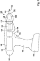
- Fig. 3 shows the hand tool 100 of Fig. 1 with a replaceable tool attachment 600 and an additional handle 350.
- the hand tool 100 illustratively has, in addition to the components described above on the one hand on the tool housing 105 on a slide switch 125, which serves a gear change of the transmission 109 of Fig. 1 and on the other hand, a preferred rubberized rotary ring 130 for adjusting a torque value, from which the optional torque clutch 199 of Fig. 1 in operation addresses.
- mounting interface 550 of preferably designed as sg "inline Schlagvorsatz” or "inline chisel attachment” tool attachment 600 by means of an attachment housing 610 of the Maschinenvorsatzes 600 trained attachment interface 602 attached.
- an attachment housing 610 of the Maschinenvorsatzes 600 trained attachment interface 602 attached to a tool holder 606 of the tool attachment 600.
- the insert tool 150 of Fig. 1 This is exemplified by a chisel 612.
- an additional handle 350 and a mounting aid 352 are also provided.
- the auxiliary handle 350 allows two handed operation of the hand tool 100 with the attached tool attachment 600, while the attachment aid 352 for temporary attachment to a garment, such as a belt or a trouser or jacket pocket, is used.
- the auxiliary handle 350 can be separated from the mounting aid 352 if necessary.
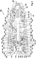
- Fig. 4 shows the tool attachment 600 of Fig. 3 , which by way of example has a fastening interface 602 designated below as “intent interface” for the purpose of clarity of the description, a drive unit 604 hereinafter also referred to as a “drive section” and a tool receptacle 606 hereinafter also referred to as a "receiving section".
- This illustratively has an SDS-plus or SDS-Quick receptacle 608 provided with a locking or actuating sleeve 695 for the preferred reception of the bit 612 of FIG Fig. 3 but can also have any other receptacle, eg a HEX receptacle, etc.
- the drive unit 604 has, for example, a percussion mechanism 640 configured in the manner of a mechanical percussion mechanism. Therefore, in order to simplify the description, the tool attachment 600 will be referred to as the "percussion attachment 600" in the further description.
- the drive section 604 has an attachment housing 610, which preferably has an outer, eg rubberized grip region 611.
- a drums 640 associated, rotationally driven drive member 697 is rotatably mounted in a bearing element 677.
- the drive member 697 is preferably arranged coaxially to the receiving portion 606 and serves to drive a driven member 698 via an associated, preferably activatable transmission 700 and the percussion 640, wherein the output member 698 according to the invention at least in a percussion operation against rotation within the attachment housing 610 is stored.
- the output member 698 has a guide section 652, which is at least partially enclosed by a tool holder 655 assigned to the attachment housing 610.
- an engagement contour 657 to provide a rotationally fixed at least in impact operation of the tool attachment 600 coupling between the tool holder holder 655 and attached to the attachment housing 610 guide portion 652 is provided.
- an annular flange 624 is formed on the driven member 698 in the region of the tool holder 655 at its axial side facing the striking mechanism 640 in order to prevent the driven member 698 from slipping out of the attachment housing 610.
- a support ring 625 for supporting a spring element 626, which rests against a plate-shaped engagement member 627 arranged in the receiving section 606 or in its locking or actuating sleeve 695.
- the spring element 626 designed in the manner of a frusto-conical pressure spring biases the locking or actuating sleeve 695 via the biasing member 627 in an axial direction pointing away from the attachment housing 610, as indicated by an arrow 601.
- the output member 698 is preferably a driven spindle which is associated with the receiving portion 606 and rotatable about a rotational axis 619, wherein the rotational axis 619 coincides with a corresponding drive axis 618 of the percussion mechanism 640 or a corresponding axis of rotation of the drive member 697.
- the percussion 640 is designed in the manner of a so-called "inline percussion" for direct impact drive of the output member 698 and the output spindle in impact operation of Schlagtechnikvorsatzes 600, wherein the output member 698 and the output spindle is adapted to corresponding impact pulses directly to the therein arranged insert tool 150 and the chisel 612 of Fig. 3 transferred to.
- a damping member 622 is provided in the attachment housing 610, which has a preferably formed as a locking ring securing element 621 and an annular base 623 is fixed in the region of the tool holder 655.
- the percussion mechanism 640 has a striking element 641 acted upon by a spring element 642, which is coupled via a ball guide 680 and a spherical tensioning element 645 to an associated spring tensioning element 646.
- the spring element 642 is preferably designed as a cylindrical compression spring. Of the Impactor 641 is preferably provided for the execution of axially aligned shocks, ie strikes in the direction of the arrow 601, against the output member 698 and the output spindle.
- the spring biasing member 646 is exemplified sleeve-shaped and with its front, the impactor 641 facing axial end 643 received in this, wherein in the region between the spring biasing member 646 and the impactor 641, the spherical clamping element 645 is arranged.
- This is arranged on the one hand in a radial recess 644 of the impactor body 641 and on the other hand can roll in a control cam 647 formed on the inner circumference of the spring tensioning member 646.
- Illustrated position of the spherical clamping element 645 corresponds illustratively a relaxed rest position 689 of the percussion mechanism 640, in which after the execution of an axial impact of the impactor 641 against the output member 698, the spring element 642 is maximally expanded and the impactor 641 rests against the annular flange 624 of the output member 698.
- a further axial impact is carried out by the release of the spherical clamping element 645 and thereby causing re-tensioning or compressing the spring element 642 by means of the rotating spring clamping member 646, a further axial impact.
- the spring tensioning member 646 receives the drive member 697, wherein the spring tensioning member 646 is arranged rotatably and thus independently of the drive member 697 on this.
- the activatable gear 700 which is activatable at least in impact operation of the percussion 640 and illustratively formed in the manner of a single-stage planetary gear with a drivable by the drive member 697 planet carrier 615 and a plurality of planetary gears 682. These are drivingly coupled to the spring tensioning member 646 via a rotational engagement toothing 648 and arranged in an associated ring gear 650.
- This is fixed to the housing and secured against rotation in the attachment housing 610 and has an impactor 641 facing axial end in which a further bearing element 679, such as a rolling bearing for rotatably supporting the spring tensioning member 646 is preferably arranged radially and axially immovable, and one of the impactor 641st facing away from and the intent interface 602 axial end on which the planet gears 682 attack.
- a further bearing element 679 such as a rolling bearing for rotatably supporting the spring tensioning member 646 is preferably arranged radially and axially immovable, and one of the impactor 641st facing away from and the intent interface 602 axial end on which the planet gears 682 attack.
- an engagement clutch 620 which is preferably actuatable by an axial displacement of the output member 698 or the output spindle against the spring force of a spring member 699.
- the output member 698 is biased axially by means of the spring member 699, preferably designed as a compression spring, in a direction pointing away from a locking unit 669 or in the direction of the arrow 601.
- the engagement clutch 620 is configured to, upon actuation against the force exerted by the spring member 699, drive the spring biasing member 646 to periodically tension and release the spring member 642, i. to enable the activation of the impact mode.
- this preferably has an approximately conical axial end 701, which is received in an approximately cylindrical bore 702 of the drive member 697.
- the cone-shaped axial end 701 after overcoming the spring force applied by the spring member 699, at least two spherical coupling bodies 703, 704 are pushed radially outwardly to turn on impact operation, so that a form-locking connection is made between the drive member 697 and the planetary carrier 615 of the transmission 700.
- the spring member 699 is added to secure the position or guidance in sections in a small hole 705 in the free axial end 701 of the output member 698 and the output spindle and is based on a non-designated hole bottom of the bore 702 of the drive member 697 from.
- the operation of the impact mechanism 640 and more details on components thereof are, for example, in the DE 10 2013 208 882.5 described, the disclosure of which is explicitly included in the present description, so that here for the sake of brevity of the description can be dispensed with a detailed description thereof.
- a remote from the drive portion 604, free axial end of the drive member 697 has at least partially a hexagonal outer periphery 665.
- an at least partially sleeve-shaped or tubular-shaped Winkeleinstellelement 672 is arranged, through which the drive member 697 engages at least in sections.
- This Winkeleinstellelement 672 is preferably rigid, ie axially and radially immovable, connected to the attachment housing 610 and / or formed integrally therewith.
- the Winkeleinstellelement 672 has at its the drive portion 604 axial end facing an outer annular collar 609 which is axially and radially stationary in the attachment housing 610, for example by pressing or jamming, and axially against the ring gear 650 of the transmission 700.
- This annular collar 609 is preferably formed on its inner circumference as a receptacle for the planetary carrier 615.
- an end-side Winkeleinstellvertechnikung 674 is provided at its other axial end 671.
- an actuating member 688 is formed on the drive member 697, which surrounds the drive member 697 at least partially sleeve-shaped and the axial loading of the locking sleeve 149 of Fig. 2 when connecting or disconnecting the tool attachment 600 is used.
- the drive member 697 and the actuator 688 may be formed in two or more pieces.
- the actuating member 688 is arranged for example in the interior of the Winkeleinstellelements 672 and preferably radially on all sides evenly spaced therefrom positioned.
- the attachment interface 602 serves for the producible and releasable attachment of the percussion attachment 600 to an associated hand-held power tool, for example the hand tool 100 of FIG Fig. 1 , or their machine interface 550 of Fig. 2 and illustratively has an angular position setting unit 670 associated with the angle adjusting element 672 and a locking unit 669.
- the locking unit 669 is configured to lock the tool attachment 600 in a locked state for operation on the hand tool at a predetermined angular position thereon and in a locked position Unlocking state to allow removal of Schlagtechnikvorsatzes 600 of the power tool.
- the Winkelpositionseinstelltechnik 670 is adapted to allow adjustment of the predetermined angular position of the percussion attachment 600 for operation on the power tool.
- the angular position setting unit 670 is preferably operable in the locking state of the locking unit 669 to allow a change in the predetermined angular position.
- Such an operation for changing the predetermined angular position is preferably carried out by a combined longitudinal and rotational movement of the attachment housing 610th
- the locking unit 669 has a locking body 632 and a rotatably mounted in this spring-loaded centering 681.
- This centering body 681 is connected via suitable fastening elements 683, e.g. Screws, secured against rotation on an axial end collar 605 of the Winkeleinstellelements 672, in which the bearing element 677 is arranged.
- the centering element 631 has at least one centering element 631, which is e.g. at least two arcuate, in the longitudinal direction of Schlagtechnikvorsatzes 600, i. opposite to the direction 601, bevelled centering areas 676, 678 has.
- centering member 631 has the two centering regions 676, 678 merely by way of example and not for the purpose of limiting the invention. Rather, the centering member 631 can also have a single centering region designed in the manner of a truncated cone.
- the locking body 632 preferably has at least two locking elements 666, 668, which are exemplified in the manner of bayonets to form a bayonet connection. Furthermore, an actuating ring 664 is arranged on the outer circumference of this locking body 632 by way of example, which can be actuated for locking the locking body 632 on the handheld power tool, wherein the locking body 632 and the actuating ring 664 can be formed in one piece.
- an optional, at least partially resilient blocking and blocking member 607 is arranged in the region between the locking body 632 and the actuating ring 664 in the region between the locking body 632 and the actuating ring 664.
- This is fixed in position, at least in sections, on the locking body 632 and / or the actuating ring 664 and designed to prevent the locking body 632 from rotating from its locking position into its unlocked position in the locking state of the locking unit 669, the blocking and blocking member 607 preferably being connected to the machine interface 550 from Fig. 2 associated blocking element 555 of Fig. 2 interacts.
- the actuating ring 664 is preferably designed to at least partially block the blocking and blocking member 607 in the locking state of the locking unit 669 against the machine interface 550 of FIG Fig. 2 to act on.
- the locking and blocking member 607 is hereby adapted to the actuating ring 664 in the locking state of the locking unit 669 in a blocking position on the locking body 632 to prevent an automatic rotation or a release of the actuating ring 664 relative to the locking body 632.
- Fig. 5 shows the tool attachment 600, which has the locking unit 669, which by means of the actuating ring 664 by the user for locking on the machine interface 550 of Fig. 2 is rotatable.
- the locking unit 669 has the approximately annular locking body 632 on which the two diametrically arranged, each formed in the manner of bayonets locking elements 666, 668 are formed.
- the rotatable by means of the actuating ring 664 locking body 632 is in this case arranged concentrically to the axis of rotation 619 of the drive member 697.
- the drive member 697 of the tool attachment 600 preferably has a hexagonal outer periphery 665 for producing a rotationally fixed, but axially movable positive connection with the tool holder 140 of the machine interface 550 of FIG Fig. 2 ,
- the rubberized grip region 611 is preferably formed at least in the area of the drive unit 604 in order to optimize the ease of operation.
Landscapes
- Engineering & Computer Science (AREA)
- Mechanical Engineering (AREA)
- Percussive Tools And Related Accessories (AREA)
Claims (13)
- Adaptateur d'outil (600) pour une machine-outil portative (100) qui comprend un boîtier d'outil (105) doté d'une interface de fixation (550), l'adaptateur d'outil comprenant un boîtier d'adaptateur (610) sur lequel sont disposés une unité de verrouillage (669) servant à verrouiller l'adaptateur d'outil (600) sur l'interface de fixation (550) de la machine-outil portative (100) et un logement d'outil (606) servant à loger un outil d'insertion (150), un mécanisme de percussion (640) étant disposé dans le boîtier d'adaptateur (610), lequel mécanisme de percussion est conçu pour, en mode de percussion de l'adaptateur d'outil (600), solliciter un outil d'insertion (150) disposé dans le logement d'outil (606) avec des percussions effectuées dans la direction axiale par rapport au logement d'outil (606), le logement d'outil (606) étant fixé en position de manière bloquée en rotation dans le boîtier d'adaptateur (610) au moins en mode de percussion, caractérisé en ce que le logement d'outil (606) comprend un élément de sortie (698) pouvant tourner autour d'un axe de rotation (619) associé, l'axe de rotation (619) coïncidant avec un axe d'entraînement (618) du mécanisme de percussion (640), et l'élément de sortie (698) comprenant une partie de guidage (652) qui est entourée au moins dans certaines zones par un support de logement d'outil (655) associé au boîtier d'adaptateur (610), au moins un contour d'engagement (657) étant prévu au moins dans certaines zones entre la partie de guidage (652) et le support de logement d'outil (655), lequel contour d'engagement sert à produire un accouplement bloqué en rotation entre le support de logement d'outil (655) et la partie de guidage (652) au moins en mode de percussion de l'adaptateur d'outil (600).
- Adaptateur d'outil selon la revendication 1, caractérisé en ce qu'un élément d'entraînement (697) disposé de manière coaxiale au logement d'outil (606) est associé au mécanisme de percussion (640).
- Adaptateur d'outil selon la revendication 2, caractérisé en ce que l'élément d'entraînement (697) présente, au moins dans certaines zones, une périphérie extérieure hexagonale (665).
- Adaptateur d'outil selon l'une quelconque des revendications précédentes, caractérisé en ce que le mécanisme de percussion (640) est conçu pour, en mode de percussion de l'adaptateur d'outil (600), entraîner directement en percussion l'élément de sortie (698) associé au logement d'outil (606), l'élément de sortie (698) étant conçu pour transmettre des percussions effectuées dans la direction axiale par rapport au logement d'outil (606) directement à un outil d'insertion (150) disposé dans le logement d'outil (606).
- Adaptateur d'outil selon l'une quelconque des revendications précédentes, caractérisé en ce que le mécanisme de percussion (640) comprend un corps de percussion (641) sollicité par un élément ressort (642), lequel corps de percussion est accouplé à un élément de tension de ressort (646) associé par le biais d'un guide de bille (680).
- Adaptateur d'outil selon l'une quelconque des revendications précédentes, caractérisé en ce que le mécanisme de percussion (640) comprend un embrayage d'engagement (620) pouvant être actionné et servant à activer le mode de percussion du mécanisme de percussion (640).
- Adaptateur d'outil selon l'une quelconque des revendications précédentes, caractérisé en ce que l'élément de sortie (698) est précontraint axialement, au moyen d'un élément ressort (699), dans un sens opposé à l'unité de verrouillage (669).
- Adaptateur d'outil selon les revendications 6 et 7, caractérisé en ce que l'embrayage d'engagement (620) est conçu pour, lors d'un actionnement à l'encontre de l'action de force exercée par l'élément ressort (699), permettre un entraînement de l'élément de tension de ressort (646) pour tendre et relâcher périodiquement l'élément ressort (642).
- Adaptateur d'outil selon l'une quelconque des revendications précédentes, caractérisé en ce que le mécanisme de percussion (640) comprend un corps de percussion (641) sollicité par un élément ressort (642), lequel corps de percussion est accouplé à un élément de tension de ressort (646) associé, une transmission (700) étant disposée dans le boîtier d'adaptateur (610), laquelle est conçue pour augmenter une vitesse de rotation de l'élément de tension de ressort (646) par rapport à une vitesse de rotation de l'élément d'entraînement (697).
- Adaptateur d'outil selon l'une quelconque des revendications précédentes, caractérisé en ce qu'une poignée supplémentaire (350) et/ou un auxiliaire de fixation (352) peuvent être fixés au boîtier d'adaptateur (610).
- Adaptateur d'outil selon l'une quelconque des revendications précédentes, caractérisé en ce que le logement d'outil (606) est conçu pour loger des outils d'insertion SDS-plus, SDS-Quick et/ou HEX.
- Adaptateur d'outil selon l'une quelconque des revendications précédentes, caractérisé en ce que l'outil d'insertion (150) est réalisé sous forme de burin.
- Système d'outil comprenant une machine-outil portative (100) qui comprend un boîtier d'outil (105) doté d'une interface de fixation (550), et comprenant un adaptateur d'outil (600) interchangeable selon l'une quelconque des revendications 1 à 12.
Applications Claiming Priority (1)
| Application Number | Priority Date | Filing Date | Title |
|---|---|---|---|
| DE102015206634.7A DE102015206634A1 (de) | 2015-04-14 | 2015-04-14 | Werkzeugvorsatz für eine Handwerkzeugmaschine |
Publications (2)
| Publication Number | Publication Date |
|---|---|
| EP3081341A1 EP3081341A1 (fr) | 2016-10-19 |
| EP3081341B1 true EP3081341B1 (fr) | 2019-01-02 |
Family
ID=55650090
Family Applications (1)
| Application Number | Title | Priority Date | Filing Date |
|---|---|---|---|
| EP16159670.5A Active EP3081341B1 (fr) | 2015-04-14 | 2016-03-10 | Ensemble d'outils pour une machine-outil portative |
Country Status (3)
| Country | Link |
|---|---|
| US (1) | US10661421B2 (fr) |
| EP (1) | EP3081341B1 (fr) |
| DE (1) | DE102015206634A1 (fr) |
Cited By (2)
| Publication number | Priority date | Publication date | Assignee | Title |
|---|---|---|---|---|
| USD1023710S1 (en) | 2021-03-19 | 2024-04-23 | Black & Decker Inc. | Power tool |
| USD1067007S1 (en) | 2021-03-19 | 2025-03-18 | Black & Decker Inc. | Attachment head for power tool |
Families Citing this family (11)
| Publication number | Priority date | Publication date | Assignee | Title |
|---|---|---|---|---|
| CN107106211B (zh) * | 2014-09-16 | 2020-02-04 | A.M.外科有限公司 | 用于将固定元件驱动到骨骼中的装置及其使用方法 |
| US20170252833A1 (en) * | 2016-03-04 | 2017-09-07 | Victor Martin BAYONA SALAZAR | Rigid self retracting ergonomic telescopic device, for drills that protects the user, collects wastes, fixed measurement drilling, increases the contact area, allow the total viewing and if it's necessary dosing lubrication; and its assembly process |
| DE102016214616A1 (de) * | 2016-08-05 | 2018-02-08 | Robert Bosch Gmbh | Vorsatzvorrichtung |
| WO2019183311A1 (fr) * | 2018-03-23 | 2019-09-26 | Milwaukee Electric Tool Corporation | Mécanisme de fixation destiné à un outil électrique |
| EP3823781A4 (fr) * | 2018-07-18 | 2022-07-27 | Apex Brands, Inc. | Perceuse mécanique portative à pompe |
| US12466038B2 (en) * | 2019-10-29 | 2025-11-11 | Atlas Copco Industrial Technique Ab | Socket for a tightening tool |
| EP3848162A1 (fr) * | 2020-01-10 | 2021-07-14 | Hilti Aktiengesellschaft | Système d'outil et procédé de raccordement d'un dispositif aspirateur à un outil |
| JP7837146B2 (ja) * | 2021-07-21 | 2026-03-30 | 株式会社マキタ | 電動工具 |
| JP1710821S (ja) * | 2021-08-05 | 2022-03-25 | 携帯用電気ハンマードリル本体 | |
| WO2025117585A1 (fr) | 2023-11-30 | 2025-06-05 | Stanley Black & Decker, Inc. | Outil électrique à têtes multiples et système de fixation associé et systèmes de fixation de têtes sur celui-ci |
| US12594657B2 (en) | 2023-11-30 | 2026-04-07 | Stanley Black & Decker, Inc. | Multi-headed power tool and systems for fastening heads thereon |
Family Cites Families (56)
| Publication number | Priority date | Publication date | Assignee | Title |
|---|---|---|---|---|
| US1665173A (en) * | 1925-08-10 | 1928-04-03 | John I Misener | Hammer attachment for electric drills and the like |
| US2724573A (en) * | 1954-07-26 | 1955-11-22 | Axel E Lundquist | Percussion attachment for portable drills |
| US3097858A (en) * | 1961-05-11 | 1963-07-16 | Skil Corp | Adapter and retainer assembly for nonrotary tool elements used with a rotary-hammer device |
| NL147356B (nl) * | 1965-03-05 | 1975-10-15 | Tech Metaalproducten Huygmetaa | Hameraanzethuis voor een boormotorhuis. |
| US4007795A (en) * | 1976-02-13 | 1977-02-15 | Skil Corporation | Attachment for a rotary-hammer tool |
| US4111060A (en) * | 1976-11-22 | 1978-09-05 | Fulvio Nerini | Drill attachment for converting rotary motion to reciprocatory motion |
| US4489792A (en) * | 1981-05-28 | 1984-12-25 | Fahim Atef E F | Hammer drill adapter |
| US4450919A (en) * | 1983-01-03 | 1984-05-29 | Cousineau Bernard L | Drill attachment |
| DE3522255A1 (de) * | 1985-06-21 | 1987-01-02 | Fischer Artur Dr H C | In einen bohrhammer bzw. schlagbohrmaschine einspannbare vorrichtung |
| JPS62124883A (ja) * | 1985-11-26 | 1987-06-06 | 芝浦メカトロニクス株式会社 | ロ−タリ−ハンマ |
| DE4135240A1 (de) * | 1991-10-25 | 1993-04-29 | Bosch Gmbh Robert | Bohrhammer |
| US5329802A (en) * | 1993-03-23 | 1994-07-19 | Nunez Delio A | Automatic slide hammer attachment |
| DE59600036D1 (de) * | 1995-03-24 | 1997-12-04 | Hilti Ag | Vorrichtung zur Übertragung von impulsartigen Schlägen auf ein kontinuierlich rotierendes Werkzeug |
| DE19604169A1 (de) * | 1996-02-06 | 1997-08-07 | Bosch Gmbh Robert | Halterung eines Zusatzgeräts für Handwerkzeugmaschinen |
| US5711380A (en) * | 1996-08-01 | 1998-01-27 | Chen; Yueh | Rotate percussion hammer/drill shift device |
| ATE345904T1 (de) * | 1997-01-30 | 2006-12-15 | Hilti Ag | Vorrichtung zur uebertragung von impulsartigen axialen schlägen auf ein bohrwerkzeug |
| US5992538A (en) * | 1997-08-08 | 1999-11-30 | Power Tool Holders Incorporated | Impact tool driver |
| GB9718312D0 (en) * | 1997-08-30 | 1997-11-05 | Black & Decker Inc | Power tool |
| US6223833B1 (en) * | 1999-06-03 | 2001-05-01 | One World Technologies, Inc. | Spindle lock and chipping mechanism for hammer drill |
| US20030089509A1 (en) * | 2000-01-22 | 2003-05-15 | Helmut Wanek | Hand machine tool |
| US7096972B2 (en) * | 2002-09-17 | 2006-08-29 | Orozco Jr Efrem | Hammer drill attachment |
| GB0311045D0 (en) * | 2003-05-14 | 2003-06-18 | Black & Decker Inc | Rotary hammer |
| US20060254044A1 (en) * | 2004-11-30 | 2006-11-16 | Hao Xu F | Power tool assembly |
| EP1674207B1 (fr) * | 2004-12-23 | 2008-12-10 | BLACK & DECKER INC. | Outil motorisé |
| GB2423044A (en) * | 2005-02-10 | 2006-08-16 | Black & Decker Inc | Hammer with cam-actuated driven member |
| US20060237205A1 (en) * | 2005-04-21 | 2006-10-26 | Eastway Fair Company Limited | Mode selector mechanism for an impact driver |
| DE102005041447A1 (de) * | 2005-08-31 | 2007-03-01 | Robert Bosch Gmbh | Bohrhammer |
| DE102005048345A1 (de) * | 2005-10-10 | 2007-04-12 | Robert Bosch Gmbh | Handwerkzeugmaschinenzusatzeinheit |
| DE102006029363A1 (de) * | 2006-06-27 | 2008-01-03 | Robert Bosch Gmbh | Elektrohandwerkzeug |
| US20100038104A1 (en) * | 2006-07-10 | 2010-02-18 | Otto Baumann | Hand held machine tool |
| SE0602364L (sv) * | 2006-11-08 | 2008-04-15 | Atlas Copco Tools Ab | Kraftverktyg med utbytbar växelenhet |
| CN201124406Y (zh) * | 2007-12-21 | 2008-10-01 | 姚耕 | 电钻多功能转换器 |
| TWI350236B (en) * | 2008-08-20 | 2011-10-11 | Bo Shen Chen | Power tool connector with imapct and vibration function |
| WO2011087542A2 (fr) * | 2009-10-23 | 2011-07-21 | California Institute Of Technology | Amplificateur à percussion de perceuses rotatives pour fonctionnement en tant que marteau perforateur rotatif |
| US8157021B2 (en) * | 2009-11-29 | 2012-04-17 | Chen Bo-Shen | Chisel adapter |
| EP2674259B1 (fr) * | 2009-12-18 | 2017-11-01 | Techtronic Power Tools Technology Limited | Système d'outil multifonction |
| US20130020106A1 (en) * | 2011-07-18 | 2013-01-24 | Black & Decker Inc. | Power tool |
| US20130228355A1 (en) * | 2011-07-18 | 2013-09-05 | Black & Decker Inc. | Power tool |
| US9776315B2 (en) * | 2011-11-11 | 2017-10-03 | Black & Decker Inc. | Power tool having interchangeable tool heads with an independent accessory switch |
| DE102011089913A1 (de) * | 2011-12-27 | 2013-06-27 | Robert Bosch Gmbh | Handwerkzeugvorrichtung |
| US9808925B2 (en) * | 2012-03-22 | 2017-11-07 | Hitachi Koki Co., Ltd. | Impact tool |
| WO2014075165A1 (fr) * | 2012-11-14 | 2014-05-22 | British Columbia Cancer Agency Branch | Accessoire de marteau perforateur tubulaire |
| DE102013213806A1 (de) * | 2012-11-15 | 2014-05-15 | Robert Bosch Gmbh | Werkzeugvorsatz für eine Handwerkzeugmaschine |
| DE102013213816A1 (de) * | 2012-11-15 | 2014-05-15 | Robert Bosch Gmbh | Wekzeugvorsatz für eine Handwerkzeugmaschine |
| DE102013213814A1 (de) * | 2012-11-15 | 2014-05-15 | Robert Bosch Gmbh | Werkzeugvorsatz für eine Handwerkzeugmaschine |
| US10011008B2 (en) * | 2012-11-15 | 2018-07-03 | Robert Bosch Gmbh | Tool attachment for a hand-held machine tool |
| DE102013213804A1 (de) * | 2012-11-22 | 2014-05-22 | Robert Bosch Gmbh | Werkzeugvorsatz für eine Handwerkzeugmaschine |
| US10259111B2 (en) * | 2013-04-03 | 2019-04-16 | Robert Bosch Gmbh | Tool attachment for a hand-held power tool |
| US9956677B2 (en) * | 2013-05-08 | 2018-05-01 | Black & Decker Inc. | Power tool with interchangeable power heads |
| DE102013208882A1 (de) | 2013-05-14 | 2014-11-20 | Robert Bosch Gmbh | Handwerkzeugvorrichtung |
| DE202013008724U1 (de) * | 2013-09-30 | 2015-01-05 | Robert Bosch Gmbh | Werkzeugvorsatz für eine Handwerkzeugmaschine |
| WO2015083268A1 (fr) * | 2013-12-05 | 2015-06-11 | 株式会社小林工具製作所 | Dispositif à mouvement alternatif rectiligne utilisant une perceuse électrique |
| DE102014224591B4 (de) * | 2014-05-07 | 2025-12-18 | Robert Bosch Gmbh | Werkzeugvorsatz sowie Werkzeugsystem |
| JP6309881B2 (ja) * | 2014-11-14 | 2018-04-11 | 株式会社マキタ | 作業工具 |
| DE102015015321B4 (de) * | 2014-11-28 | 2024-10-24 | Makita Corporation | Schlagwerkzeug mit Vibrationsdämpfung |
| US20170197305A1 (en) * | 2016-01-10 | 2017-07-13 | Omnitek Partners Llc | Chisel Head Attachment For Electric Drills and Screw Drivers and the Like and Electric Chisels |
-
2015
- 2015-04-14 DE DE102015206634.7A patent/DE102015206634A1/de not_active Withdrawn
-
2016
- 2016-03-10 EP EP16159670.5A patent/EP3081341B1/fr active Active
- 2016-03-14 US US15/069,668 patent/US10661421B2/en active Active
Non-Patent Citations (1)
| Title |
|---|
| None * |
Cited By (2)
| Publication number | Priority date | Publication date | Assignee | Title |
|---|---|---|---|---|
| USD1023710S1 (en) | 2021-03-19 | 2024-04-23 | Black & Decker Inc. | Power tool |
| USD1067007S1 (en) | 2021-03-19 | 2025-03-18 | Black & Decker Inc. | Attachment head for power tool |
Also Published As
| Publication number | Publication date |
|---|---|
| EP3081341A1 (fr) | 2016-10-19 |
| DE102015206634A1 (de) | 2016-10-20 |
| US10661421B2 (en) | 2020-05-26 |
| US20160303729A1 (en) | 2016-10-20 |
Similar Documents
| Publication | Publication Date | Title |
|---|---|---|
| EP3081341B1 (fr) | Ensemble d'outils pour une machine-outil portative | |
| EP2981395B1 (fr) | Adaptateur d'outil destiné à une machine-outil manuelle | |
| EP2745992B1 (fr) | Ensemble d'outils pour une machine-outil manuelle | |
| EP2745990B1 (fr) | Ensemble d'outils pour une machine-outil manuelle | |
| DE102014207713B4 (de) | Werkzeugvorsatz für eine Handwerkzeugmaschine | |
| EP2585241B1 (fr) | Machine-outil portative pourvue d'un mécanisme de percussion | |
| DE202013008724U1 (de) | Werkzeugvorsatz für eine Handwerkzeugmaschine | |
| EP2295206B1 (fr) | Machine-outil à main électrique combinée | |
| EP2745991A2 (fr) | Ensemble d'outils pour une machine-outil manuelle | |
| DE102004030760A1 (de) | Vorrichtung mit einer Drehmomentbegrenzungseinheit | |
| DE102011084499A1 (de) | Werkzeugvorsatz | |
| EP2262601A1 (fr) | Machine-outil à main | |
| WO2017211554A1 (fr) | Adaptateur pour serrage rapide | |
| EP2632641A1 (fr) | Organe de percussion mécanique pour une machine-outil à main | |
| DE102015206622A1 (de) | Werkzeugvorsatz für eine Handwerkzeugmaschine | |
| EP3053708B1 (fr) | Dispositif auxiliaire | |
| EP2745993B1 (fr) | Ensemble d'outils pour une machine-outil manuelle | |
| DE102012220905A1 (de) | Handwerkzeugmaschine mit einer Befestigungsschnittstelle | |
| DE102013204225A1 (de) | Handwerkzeugmaschine mit einer Antriebswelle zum drehenden Antrieb einer Werkzeugaufnahme | |
| WO2018024475A1 (fr) | Dispositif adaptateur | |
| EP2632642B1 (fr) | Machine-outil à main pourvue d'un organe de percussion mécanique | |
| DE102016224186A1 (de) | Adaptervorsatz zum Einspannen eines Rundschafteinsatzwerkzeugs | |
| DE102023212814A1 (de) | Handwerkzeugmaschine | |
| DE202008004563U1 (de) | Zusatzhandgriff |
Legal Events
| Date | Code | Title | Description |
|---|---|---|---|
| PUAI | Public reference made under article 153(3) epc to a published international application that has entered the european phase |
Free format text: ORIGINAL CODE: 0009012 |
|
| AK | Designated contracting states |
Kind code of ref document: A1 Designated state(s): AL AT BE BG CH CY CZ DE DK EE ES FI FR GB GR HR HU IE IS IT LI LT LU LV MC MK MT NL NO PL PT RO RS SE SI SK SM TR |
|
| AX | Request for extension of the european patent |
Extension state: BA ME |
|
| STAA | Information on the status of an ep patent application or granted ep patent |
Free format text: STATUS: REQUEST FOR EXAMINATION WAS MADE |
|
| 17P | Request for examination filed |
Effective date: 20170419 |
|
| RBV | Designated contracting states (corrected) |
Designated state(s): AL AT BE BG CH CY CZ DE DK EE ES FI FR GB GR HR HU IE IS IT LI LT LU LV MC MK MT NL NO PL PT RO RS SE SI SK SM TR |
|
| GRAP | Despatch of communication of intention to grant a patent |
Free format text: ORIGINAL CODE: EPIDOSNIGR1 |
|
| STAA | Information on the status of an ep patent application or granted ep patent |
Free format text: STATUS: GRANT OF PATENT IS INTENDED |
|
| INTG | Intention to grant announced |
Effective date: 20180821 |
|
| GRAS | Grant fee paid |
Free format text: ORIGINAL CODE: EPIDOSNIGR3 |
|
| GRAA | (expected) grant |
Free format text: ORIGINAL CODE: 0009210 |
|
| STAA | Information on the status of an ep patent application or granted ep patent |
Free format text: STATUS: THE PATENT HAS BEEN GRANTED |
|
| AK | Designated contracting states |
Kind code of ref document: B1 Designated state(s): AL AT BE BG CH CY CZ DE DK EE ES FI FR GB GR HR HU IE IS IT LI LT LU LV MC MK MT NL NO PL PT RO RS SE SI SK SM TR |
|
| REG | Reference to a national code |
Ref country code: GB Ref legal event code: FG4D Free format text: NOT ENGLISH |
|
| REG | Reference to a national code |
Ref country code: CH Ref legal event code: EP Ref country code: AT Ref legal event code: REF Ref document number: 1083760 Country of ref document: AT Kind code of ref document: T Effective date: 20190115 |
|
| REG | Reference to a national code |
Ref country code: IE Ref legal event code: FG4D Free format text: LANGUAGE OF EP DOCUMENT: GERMAN |
|
| REG | Reference to a national code |
Ref country code: DE Ref legal event code: R096 Ref document number: 502016003029 Country of ref document: DE |
|
| REG | Reference to a national code |
Ref country code: NL Ref legal event code: MP Effective date: 20190102 |
|
| REG | Reference to a national code |
Ref country code: LT Ref legal event code: MG4D |
|
| PG25 | Lapsed in a contracting state [announced via postgrant information from national office to epo] |
Ref country code: NL Free format text: LAPSE BECAUSE OF FAILURE TO SUBMIT A TRANSLATION OF THE DESCRIPTION OR TO PAY THE FEE WITHIN THE PRESCRIBED TIME-LIMIT Effective date: 20190102 |
|
| PG25 | Lapsed in a contracting state [announced via postgrant information from national office to epo] |
Ref country code: FI Free format text: LAPSE BECAUSE OF FAILURE TO SUBMIT A TRANSLATION OF THE DESCRIPTION OR TO PAY THE FEE WITHIN THE PRESCRIBED TIME-LIMIT Effective date: 20190102 Ref country code: SE Free format text: LAPSE BECAUSE OF FAILURE TO SUBMIT A TRANSLATION OF THE DESCRIPTION OR TO PAY THE FEE WITHIN THE PRESCRIBED TIME-LIMIT Effective date: 20190102 Ref country code: LT Free format text: LAPSE BECAUSE OF FAILURE TO SUBMIT A TRANSLATION OF THE DESCRIPTION OR TO PAY THE FEE WITHIN THE PRESCRIBED TIME-LIMIT Effective date: 20190102 Ref country code: ES Free format text: LAPSE BECAUSE OF FAILURE TO SUBMIT A TRANSLATION OF THE DESCRIPTION OR TO PAY THE FEE WITHIN THE PRESCRIBED TIME-LIMIT Effective date: 20190102 Ref country code: NO Free format text: LAPSE BECAUSE OF FAILURE TO SUBMIT A TRANSLATION OF THE DESCRIPTION OR TO PAY THE FEE WITHIN THE PRESCRIBED TIME-LIMIT Effective date: 20190402 Ref country code: PT Free format text: LAPSE BECAUSE OF FAILURE TO SUBMIT A TRANSLATION OF THE DESCRIPTION OR TO PAY THE FEE WITHIN THE PRESCRIBED TIME-LIMIT Effective date: 20190502 Ref country code: PL Free format text: LAPSE BECAUSE OF FAILURE TO SUBMIT A TRANSLATION OF THE DESCRIPTION OR TO PAY THE FEE WITHIN THE PRESCRIBED TIME-LIMIT Effective date: 20190102 |
|
| PG25 | Lapsed in a contracting state [announced via postgrant information from national office to epo] |
Ref country code: RS Free format text: LAPSE BECAUSE OF FAILURE TO SUBMIT A TRANSLATION OF THE DESCRIPTION OR TO PAY THE FEE WITHIN THE PRESCRIBED TIME-LIMIT Effective date: 20190102 Ref country code: HR Free format text: LAPSE BECAUSE OF FAILURE TO SUBMIT A TRANSLATION OF THE DESCRIPTION OR TO PAY THE FEE WITHIN THE PRESCRIBED TIME-LIMIT Effective date: 20190102 Ref country code: GR Free format text: LAPSE BECAUSE OF FAILURE TO SUBMIT A TRANSLATION OF THE DESCRIPTION OR TO PAY THE FEE WITHIN THE PRESCRIBED TIME-LIMIT Effective date: 20190403 Ref country code: LV Free format text: LAPSE BECAUSE OF FAILURE TO SUBMIT A TRANSLATION OF THE DESCRIPTION OR TO PAY THE FEE WITHIN THE PRESCRIBED TIME-LIMIT Effective date: 20190102 Ref country code: IS Free format text: LAPSE BECAUSE OF FAILURE TO SUBMIT A TRANSLATION OF THE DESCRIPTION OR TO PAY THE FEE WITHIN THE PRESCRIBED TIME-LIMIT Effective date: 20190502 Ref country code: BG Free format text: LAPSE BECAUSE OF FAILURE TO SUBMIT A TRANSLATION OF THE DESCRIPTION OR TO PAY THE FEE WITHIN THE PRESCRIBED TIME-LIMIT Effective date: 20190402 |
|
| REG | Reference to a national code |
Ref country code: DE Ref legal event code: R097 Ref document number: 502016003029 Country of ref document: DE |
|
| PG25 | Lapsed in a contracting state [announced via postgrant information from national office to epo] |
Ref country code: EE Free format text: LAPSE BECAUSE OF FAILURE TO SUBMIT A TRANSLATION OF THE DESCRIPTION OR TO PAY THE FEE WITHIN THE PRESCRIBED TIME-LIMIT Effective date: 20190102 Ref country code: RO Free format text: LAPSE BECAUSE OF FAILURE TO SUBMIT A TRANSLATION OF THE DESCRIPTION OR TO PAY THE FEE WITHIN THE PRESCRIBED TIME-LIMIT Effective date: 20190102 Ref country code: CZ Free format text: LAPSE BECAUSE OF FAILURE TO SUBMIT A TRANSLATION OF THE DESCRIPTION OR TO PAY THE FEE WITHIN THE PRESCRIBED TIME-LIMIT Effective date: 20190102 Ref country code: AL Free format text: LAPSE BECAUSE OF FAILURE TO SUBMIT A TRANSLATION OF THE DESCRIPTION OR TO PAY THE FEE WITHIN THE PRESCRIBED TIME-LIMIT Effective date: 20190102 Ref country code: MC Free format text: LAPSE BECAUSE OF FAILURE TO SUBMIT A TRANSLATION OF THE DESCRIPTION OR TO PAY THE FEE WITHIN THE PRESCRIBED TIME-LIMIT Effective date: 20190102 Ref country code: SK Free format text: LAPSE BECAUSE OF FAILURE TO SUBMIT A TRANSLATION OF THE DESCRIPTION OR TO PAY THE FEE WITHIN THE PRESCRIBED TIME-LIMIT Effective date: 20190102 Ref country code: IT Free format text: LAPSE BECAUSE OF FAILURE TO SUBMIT A TRANSLATION OF THE DESCRIPTION OR TO PAY THE FEE WITHIN THE PRESCRIBED TIME-LIMIT Effective date: 20190102 Ref country code: DK Free format text: LAPSE BECAUSE OF FAILURE TO SUBMIT A TRANSLATION OF THE DESCRIPTION OR TO PAY THE FEE WITHIN THE PRESCRIBED TIME-LIMIT Effective date: 20190102 |
|
| REG | Reference to a national code |
Ref country code: CH Ref legal event code: PL |
|
| PLBE | No opposition filed within time limit |
Free format text: ORIGINAL CODE: 0009261 |
|
| STAA | Information on the status of an ep patent application or granted ep patent |
Free format text: STATUS: NO OPPOSITION FILED WITHIN TIME LIMIT |
|
| PG25 | Lapsed in a contracting state [announced via postgrant information from national office to epo] |
Ref country code: LU Free format text: LAPSE BECAUSE OF NON-PAYMENT OF DUE FEES Effective date: 20190310 Ref country code: SM Free format text: LAPSE BECAUSE OF FAILURE TO SUBMIT A TRANSLATION OF THE DESCRIPTION OR TO PAY THE FEE WITHIN THE PRESCRIBED TIME-LIMIT Effective date: 20190102 |
|
| 26N | No opposition filed |
Effective date: 20191003 |
|
| REG | Reference to a national code |
Ref country code: BE Ref legal event code: MM Effective date: 20190331 |
|
| PG25 | Lapsed in a contracting state [announced via postgrant information from national office to epo] |
Ref country code: LI Free format text: LAPSE BECAUSE OF NON-PAYMENT OF DUE FEES Effective date: 20190331 Ref country code: IE Free format text: LAPSE BECAUSE OF NON-PAYMENT OF DUE FEES Effective date: 20190310 Ref country code: CH Free format text: LAPSE BECAUSE OF NON-PAYMENT OF DUE FEES Effective date: 20190331 |
|
| PG25 | Lapsed in a contracting state [announced via postgrant information from national office to epo] |
Ref country code: BE Free format text: LAPSE BECAUSE OF NON-PAYMENT OF DUE FEES Effective date: 20190331 Ref country code: SI Free format text: LAPSE BECAUSE OF FAILURE TO SUBMIT A TRANSLATION OF THE DESCRIPTION OR TO PAY THE FEE WITHIN THE PRESCRIBED TIME-LIMIT Effective date: 20190102 |
|
| PG25 | Lapsed in a contracting state [announced via postgrant information from national office to epo] |
Ref country code: TR Free format text: LAPSE BECAUSE OF FAILURE TO SUBMIT A TRANSLATION OF THE DESCRIPTION OR TO PAY THE FEE WITHIN THE PRESCRIBED TIME-LIMIT Effective date: 20190102 |
|
| PG25 | Lapsed in a contracting state [announced via postgrant information from national office to epo] |
Ref country code: MT Free format text: LAPSE BECAUSE OF FAILURE TO SUBMIT A TRANSLATION OF THE DESCRIPTION OR TO PAY THE FEE WITHIN THE PRESCRIBED TIME-LIMIT Effective date: 20190102 |
|
| PG25 | Lapsed in a contracting state [announced via postgrant information from national office to epo] |
Ref country code: CY Free format text: LAPSE BECAUSE OF FAILURE TO SUBMIT A TRANSLATION OF THE DESCRIPTION OR TO PAY THE FEE WITHIN THE PRESCRIBED TIME-LIMIT Effective date: 20190102 |
|
| PG25 | Lapsed in a contracting state [announced via postgrant information from national office to epo] |
Ref country code: HU Free format text: LAPSE BECAUSE OF FAILURE TO SUBMIT A TRANSLATION OF THE DESCRIPTION OR TO PAY THE FEE WITHIN THE PRESCRIBED TIME-LIMIT; INVALID AB INITIO Effective date: 20160310 |
|
| REG | Reference to a national code |
Ref country code: AT Ref legal event code: MM01 Ref document number: 1083760 Country of ref document: AT Kind code of ref document: T Effective date: 20210310 |
|
| PG25 | Lapsed in a contracting state [announced via postgrant information from national office to epo] |
Ref country code: MK Free format text: LAPSE BECAUSE OF FAILURE TO SUBMIT A TRANSLATION OF THE DESCRIPTION OR TO PAY THE FEE WITHIN THE PRESCRIBED TIME-LIMIT Effective date: 20190102 |
|
| PG25 | Lapsed in a contracting state [announced via postgrant information from national office to epo] |
Ref country code: AT Free format text: LAPSE BECAUSE OF NON-PAYMENT OF DUE FEES Effective date: 20210310 |
|
| PGFP | Annual fee paid to national office [announced via postgrant information from national office to epo] |
Ref country code: DE Payment date: 20250522 Year of fee payment: 10 |
|
| PGFP | Annual fee paid to national office [announced via postgrant information from national office to epo] |
Ref country code: GB Payment date: 20260324 Year of fee payment: 11 |
|
| PGFP | Annual fee paid to national office [announced via postgrant information from national office to epo] |
Ref country code: FR Payment date: 20260324 Year of fee payment: 11 |