EP3081345A2 - Adaptives automatisierungssystem zur bauteilprüfung - Google Patents
Adaptives automatisierungssystem zur bauteilprüfung Download PDFInfo
- Publication number
- EP3081345A2 EP3081345A2 EP16164880.3A EP16164880A EP3081345A2 EP 3081345 A2 EP3081345 A2 EP 3081345A2 EP 16164880 A EP16164880 A EP 16164880A EP 3081345 A2 EP3081345 A2 EP 3081345A2
- Authority
- EP
- European Patent Office
- Prior art keywords
- manipulator
- component
- checking
- measuring system
- hand
- Prior art date
- Legal status (The legal status is an assumption and is not a legal conclusion. Google has not performed a legal analysis and makes no representation as to the accuracy of the status listed.)
- Withdrawn
Links
Images
Classifications
-
- B—PERFORMING OPERATIONS; TRANSPORTING
- B25—HAND TOOLS; PORTABLE POWER-DRIVEN TOOLS; MANIPULATORS
- B25J—MANIPULATORS; CHAMBERS PROVIDED WITH MANIPULATION DEVICES
- B25J9/00—Program-controlled manipulators
- B25J9/16—Program controls
-
- B—PERFORMING OPERATIONS; TRANSPORTING
- B25—HAND TOOLS; PORTABLE POWER-DRIVEN TOOLS; MANIPULATORS
- B25J—MANIPULATORS; CHAMBERS PROVIDED WITH MANIPULATION DEVICES
- B25J9/00—Program-controlled manipulators
- B25J9/16—Program controls
- B25J9/1628—Program controls characterised by the control loop
- B25J9/1633—Program controls characterised by the control loop compliant, force, torque control, e.g. combined with position control
-
- B—PERFORMING OPERATIONS; TRANSPORTING
- B25—HAND TOOLS; PORTABLE POWER-DRIVEN TOOLS; MANIPULATORS
- B25J—MANIPULATORS; CHAMBERS PROVIDED WITH MANIPULATION DEVICES
- B25J9/00—Program-controlled manipulators
- B25J9/16—Program controls
- B25J9/1656—Program controls characterised by programming, planning systems for manipulators
-
- B—PERFORMING OPERATIONS; TRANSPORTING
- B25—HAND TOOLS; PORTABLE POWER-DRIVEN TOOLS; MANIPULATORS
- B25J—MANIPULATORS; CHAMBERS PROVIDED WITH MANIPULATION DEVICES
- B25J9/00—Program-controlled manipulators
- B25J9/16—Program controls
- B25J9/1679—Program controls characterised by the tasks executed
-
- G—PHYSICS
- G05—CONTROLLING; REGULATING
- G05B—CONTROL OR REGULATING SYSTEMS IN GENERAL; FUNCTIONAL ELEMENTS OF SUCH SYSTEMS; MONITORING OR TESTING ARRANGEMENTS FOR SUCH SYSTEMS OR ELEMENTS
- G05B19/00—Program-control systems
- G05B19/02—Program-control systems electric
- G05B19/42—Recording and playback systems, i.e. in which the program is recorded from a cycle of operations, e.g. the cycle of operations being manually controlled, after which this record is played back on the same machine
-
- G—PHYSICS
- G05—CONTROLLING; REGULATING
- G05B—CONTROL OR REGULATING SYSTEMS IN GENERAL; FUNCTIONAL ELEMENTS OF SUCH SYSTEMS; MONITORING OR TESTING ARRANGEMENTS FOR SUCH SYSTEMS OR ELEMENTS
- G05B19/00—Program-control systems
- G05B19/02—Program-control systems electric
- G05B19/42—Recording and playback systems, i.e. in which the program is recorded from a cycle of operations, e.g. the cycle of operations being manually controlled, after which this record is played back on the same machine
- G05B19/423—Teaching successive positions by walk-through, i.e. the tool head or end effector being grasped and guided directly, with or without servo-assistance, to follow a path
-
- G—PHYSICS
- G05—CONTROLLING; REGULATING
- G05B—CONTROL OR REGULATING SYSTEMS IN GENERAL; FUNCTIONAL ELEMENTS OF SUCH SYSTEMS; MONITORING OR TESTING ARRANGEMENTS FOR SUCH SYSTEMS OR ELEMENTS
- G05B2219/00—Program-control systems
- G05B2219/30—Nc systems
- G05B2219/36—Nc in input of data, input key till input tape
- G05B2219/36442—Automatically teaching, teach by showing
-
- G—PHYSICS
- G05—CONTROLLING; REGULATING
- G05B—CONTROL OR REGULATING SYSTEMS IN GENERAL; FUNCTIONAL ELEMENTS OF SUCH SYSTEMS; MONITORING OR TESTING ARRANGEMENTS FOR SUCH SYSTEMS OR ELEMENTS
- G05B2219/00—Program-control systems
- G05B2219/30—Nc systems
- G05B2219/39—Robotics, robotics to robotics hand
- G05B2219/39019—Calibration by cmm coordinate measuring machine over a certain volume
-
- G—PHYSICS
- G05—CONTROLLING; REGULATING
- G05B—CONTROL OR REGULATING SYSTEMS IN GENERAL; FUNCTIONAL ELEMENTS OF SUCH SYSTEMS; MONITORING OR TESTING ARRANGEMENTS FOR SUCH SYSTEMS OR ELEMENTS
- G05B2219/00—Program-control systems
- G05B2219/30—Nc systems
- G05B2219/39—Robotics, robotics to robotics hand
- G05B2219/39028—Relative to base calibrated 6-DOF device, cmm connected between wrist and base
-
- G—PHYSICS
- G05—CONTROLLING; REGULATING
- G05B—CONTROL OR REGULATING SYSTEMS IN GENERAL; FUNCTIONAL ELEMENTS OF SUCH SYSTEMS; MONITORING OR TESTING ARRANGEMENTS FOR SUCH SYSTEMS OR ELEMENTS
- G05B2219/00—Program-control systems
- G05B2219/30—Nc systems
- G05B2219/39—Robotics, robotics to robotics hand
- G05B2219/39107—Pick up article, object, measure, test it during motion path, place it
-
- G—PHYSICS
- G05—CONTROLLING; REGULATING
- G05B—CONTROL OR REGULATING SYSTEMS IN GENERAL; FUNCTIONAL ELEMENTS OF SUCH SYSTEMS; MONITORING OR TESTING ARRANGEMENTS FOR SUCH SYSTEMS OR ELEMENTS
- G05B2219/00—Program-control systems
- G05B2219/30—Nc systems
- G05B2219/40—Robotics, robotics mapping to robotics vision
- G05B2219/40391—Human to robot skill transfer
Definitions
- the present invention relates to a method for checking a component with a multi-axis manipulator, as well as a corresponding robot system.
- this component is typically measured with a hand-held measuring system, such as a hand-held laser scanner.
- a hand-held measuring system such as a hand-held laser scanner.
- An employee usually has to perform this procedure separately for each component to be measured.
- the present invention relates to a method for checking a component with a multi-axis manipulator.
- the checking of a component, or even testing of a component may involve various aspects, which, for example, involves a quality control of a component.
- the inspection of a component can be a measurement of the component in order to compare the dimension of the component, for example, with provided CAD data.
- the axes of the multi-axis manipulator are provided with sensors for detecting torques and forces.
- sensors are preferably force-moment sensors are used, and in particular sensors based on strain gauges (DMS), which are arranged on the axes - or at least on one axis - of the manipulator. Strain gauges allow a particularly precise detection of the forces acting. More preferably, all axes of the manipulator are equipped with such force-moment sensors. Thus, a particularly effective control and monitoring of the manipulator is possible.
- DMS strain gauges
- the manipulator can be operated in at least one of its degrees of freedom by means of compliance control, wherein this compliance can be controlled in particular by means of an impedance control, an admittance control, a position control or a torque control.
- the manipulator includes a measuring system for checking the component.
- the measuring system is separably attached to a flange of the manipulator, and preferably forms the last element of a kinematic chain of the manipulator.
- the measuring system may include one or more measuring devices, which for a checking of a component are suitable.
- the measuring system comprises a laser scanner, which can measure, for example, a component.
- the inventive method for checking the component in this case has a direct guiding of the manipulator by hand, wherein the manipulator is operated in an operating mode for active compliance control.
- An operator such as an employee, controls the manipulator by guiding the manipulator by hand.
- he preferably grasps the manipulator directly, and pushes or pulls the manipulator in a desired direction.
- the manipulator can be moved in this way as desired, so it is completely soft-connected.
- the hand-held manipulator is guided directly on the measuring system, the operator thus concentrates on the movement of the measuring system, and the manipulator detects the forces and torques arising due to the direct guidance and controls its axes accordingly, so that the manipulator of the direct guidance by the operator follows.
- the "gravitational compensation" of the manipulator is activated, so that the operator does not have to move the dead weight of the manipulator, but only has to guide the manipulator.
- the dead weight of the measuring system is also already included, so that this weight is also already taken into account by the manipulator, so that ultimately a further facilitation of the movement of the manipulator when guiding by hand is achieved.
- the method according to the invention comprises determining path points of the path guided by the direct guidance of the manipulator.
- the track points of the measuring system are detected during the immediate guidance of the manipulator by hand, and further preferably deposited in a controller.
- the axis angle of the manipulator can also be determined.
- the track points are determined such that this track guided by the immediately guided track can be automatically traveled in a later step by the manipulator based on the determined track points.
- the inventive method for checking the component further includes a departure of the track points by the manipulator.
- the track points which were previously determined for the track guided by the direct guidance of the manipulator are traversed by the manipulator in this step.
- the manipulator performs the same movements as during the step of directly guiding the manipulator by hand.
- this traversing of the track points is done by an automatic control of the drives of the manipulator, that is, without that an active control is performed by an operator.
- the component is checked by means of the measuring system during the travel of the track points through the manipulator.
- the checking of the component may preferably include at least one of the following: measuring the component, measuring a dimension of the component, detecting the component, or detecting and / or checking a feature of the component. For example, a hole in a component may be detected and e.g. a diameter of the detected hole can be measured.
- the method according to the invention for checking a component it is thus possible to intuitively and easily determine track points, which track points are later automatically traversed by the manipulator for checking the component.
- An employee therefore only has to specify a path once, whereby he can intuitively specify these path points by directly guiding the manipulator by hand.
- the employee no longer has to carry or lift the hand-held measuring system himself, since the hand-held measuring system is preferably the measuring system for checking the component, which is now held by the manipulator.
- the measuring system can be adaptively guided on different components in order to enable a check or quality control of these components.
- a movement of the manipulator during the step of directly guiding the manipulator by hand is limited, so that a movement of the measuring system is possible only in one plane. If, for example, the measuring system or the manipulator is to be guided along a flat surface of a component, restricting the movement of the manipulator allows a predetermined distance between measuring device and component to be easily maintained.
- all axes of the manipulator are soft-connected, so that the manipulator can be easily guided by hand, so that the track points to be traveled can be learned easily and intuitively.
- the present invention comprises a robot system comprising a manipulator whose axes are provided with sensors for detecting torques and forces.
- the manipulator of the robot system according to the invention comprises a measuring system for checking a component.
- the robot system has a control device which is set up to carry out a method according to the invention for checking a component.
- the measuring system for checking the component preferably comprises a laser scanner.
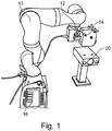
- the Fig. 1 shows a multi-axis manipulator 10 or articulated arm 10 whose axes are provided with sensors for detecting torques and forces.
- the exemplified manipulator 10 is a lightweight robot of the type KUKA LBR iiwa, which is fixedly installed in the illustrated embodiment.
- a laser scanner 14 is mounted, with which a workpiece or component 20th can be measured.
- a mobile terminal 16 is shown, which can also be used to control the manipulator 10.
- a pneumatic actuator is integrated, with which a trigger button of the laser scanner 14 (not shown) can be controlled via the manipulator 10.
- a PLC connection preferably also eliminates a PLC connection. It can therefore be used advantageously for a "manual operation" thought measuring system. Nevertheless, a deactivation / activation of the laser scanner 14 can also take place via a control of the manipulator 10 or be integrated into it.
- the manipulator can be switched in all axes or Cartesian in each of the x-, y- and z-direction.
- soft switching it is possible to guide the manipulator 10 by hand, so to press the manipulator 10 directly by hand in a desired direction.
- the manipulator 10 detects the forces and torques acting on the axles and controls its drives accordingly, so that it follows the hand guide.
- a "soft" robot or manipulator it can easily be guided by hand so that the runway can be taught in live.
- the web is recorded and stored so that it can be automatically run at any time.
- the operator can specify a selection menu in the input device 16.
- the laser scanner 14 can be deactivated, for example, in transitions from one component area to another, so that measurement errors are avoided.
- an activation and deactivation of the measuring system or laser scanner 14 is also detected or recorded and / or stored by the controller of the manipulator 10 so that the measuring system or the laser scanner 14 is likewise activated and deactivated during the automatic shutdown.
- the laser scanner 14 should have a certain distance from the component 20, the component 20 can be approached very close during the immediate guiding by hand, and then automatically a certain or predetermined distance between the laser scanner 14 and the component 20 can be adjusted.
- the corresponding automatic movement can be started, for example, via a selection menu in the input device 16.
- the distance between the laser scanner 14 and the workpiece or component 20 can also be detected automatically, and an advantageous distance can be set automatically by the manipulator 10.
- Another robot application is used to automatically remove the taught during the direct management of the manipulator 10 track points.
- An integrated in the program collision monitoring protects advantageous humans as well as the manipulator 10 and the laser scanner 14 from serious damage in the event of a collision.
- a 3D model of the component 20 is created by software from the images or image sequences recorded with the measuring system or laser scanner 14. This 3D model is then compared to a CAD model of the workpiece to determine if the manufactured component 20 corresponds to the CAD model. The component is thus checked on the basis of the recorded by the laser scanner 14 measurement data and a CAD model.
Landscapes
- Engineering & Computer Science (AREA)
- Robotics (AREA)
- Mechanical Engineering (AREA)
- Physics & Mathematics (AREA)
- General Physics & Mathematics (AREA)
- Automation & Control Theory (AREA)
- Manipulator (AREA)
Abstract
Description
- Die vorliegende Erfindung betrifft ein Verfahren zum Überprüfen eines Bauteils mit einem mehrachsigen Manipulator, als auch ein entsprechendes Robotersystem.
- Um ein Bauteil (oder ein Werkstück) einer Qualitätskontrolle zu unterziehen, wird dieses Bauteil üblicherweise mit einem Handmesssystem, wie etwa einem handgeführten Laserscanner, vermessen. Diesen Vorgang muss ein Mitarbeiter üblicherweise für jedes zu vermessende Bauteil separat durchführen.
- Obwohl solch eine Qualitätskontrolle mit einem Handmesssystem sehr adaptiv ist, ist diese Vorgehensweise mit Nachteilen verbunden. Zum einen ist das separate Führen eines Handmesssystems für jedes Bauteil aufwendig, und weiterhin wird ein Mitarbeiter benötigt, welcher auf diese Art die Qualitätskontrolle durchführt. Des Weiteren ist, da ein Mitarbeiter die Qualitätskontrolle per Hand durchführt, die Qualitätskontrolle folglich menschlichen Fehlereinflüssen ausgesetzt. Da die handgeführten Messgeräte teilweise auch sehr unergonomisch sein können (beispielsweise aufgrund ihres hohen Gewichts oder aufgrund eines unvorteilhaften Haltungswinkels, etc.), kann das Durchführen einer Qualitätskontrolle für einen Mitarbeiter entsprechend umständlich und aufwendig sein.
- Es ist somit eine Aufgabe der vorliegenden Erfindung, eine Methode bereitzustellen, welche ein einfaches und möglichst fehlerfreies Messen bzw. Überprüfen eines Bauteils erlaubt. Es ist eine weitere Aufgabe der vorliegenden Erfindung, ein System bereitzustellen, welches eine Qualitätskontrolle eines Bauteils erlaubt, wobei der Arbeitsaufwand eines Mitarbeiters reduziert wird. Eine weitere Aufgabe der vorliegenden Erfindung ist es, ein System zur Durchführung einer Qualitätskontrolle bereitzustellen, welches genaue Messaufnahmen des Bauteils liefert.
- Diese und weitere Aufgaben, welche beim Lesen der folgenden Beschreibung ersichtlich werden, werden durch den Gegenstand des Haupt- und Nebenanspruchs gelöst.
- Die vorliegende Erfindung betrifft ein Verfahren zum Überprüfen eines Bauteils mit einem mehrachsigen Manipulator. Das Überprüfen eines Bauteils, oder auch Prüfen eines Bauteils, kann dabei verschiedene Aspekte umfassen, welche beispielsweise eine Qualitätskontrolle eines Bauteils mit sich bringt. Somit kann es sich bei der Überprüfung eines Bauteils beispielsweise um ein Vermessen des Bauteils handeln, um die Dimension des Bauteils beispielsweise mit bereitgestellten CAD-Daten zu vergleichen.
- Gemäß der vorliegenden Erfindung sind die Achsen des mehrachsigen Manipulators mit Sensoren zur Erfassung von Drehmomenten und Kräften versehen. Als Sensoren kommen bevorzugt Kraft-Momenten-Sensoren zum Einsatz, und zwar insbesondere Sensoren, die auf Dehnungsmessstreifen (DMS) basieren, die an den Achsen - oder zumindest an einer Achse - des Manipulators angeordnet sind. Dehnungsmessstreifen erlauben eine besonders präzise Erfassung der wirkenden Kräfte. Weiter bevorzugt sind alle Achsen des Manipulators mit derartigen Kraft-Momenten-Sensoren ausgestattet. Somit ist eine besonders wirkungsvolle Steuerung und Überwachung des Manipulators möglich.
- Vorzugsweise kann der Manipulator in mindestens einem seiner Freiheitsgrade mittels Nachgiebigkeitsregelung betrieben werden, wobei diese Nachgiebigkeitsregelung insbesondere mittels einer Impedanzregelung, einer Admittanzregelung, einer Positionsregelung oder einer Drehmomentenregelung erfolgen kann.
- Der Manipulator umfasst ein Messsystem zum Überprüfen des Bauteils. Vorzugsweise ist das Messsystem trennbar an einem Flansch des Manipulators angebracht, und bildet vorzugsweise das letzte Element einer kinematischen Kette des Manipulators. Das Messsystem kann dabei ein oder mehrere Messvorrichtungen umfassen, welche für ein Überprüfen eines Bauteils geeignet sind. Besonders bevorzugt umfasst das Messsystem einen Laserscanner, welches beispielsweise ein Bauteil vermessen kann.
- Das erfindungsgemäße Verfahren zum Überprüfen des Bauteils weist dabei ein unmittelbares Führen des Manipulators von Hand auf, wobei der Manipulator in einem Betriebsmodus zur aktiven Nachgiebigkeitsregelung betrieben wird. Ein Bediener, wie beispielsweise ein Mitarbeiter, steuert dabei den Manipulator, indem er den Manipulator unmittelbar per Hand führt. Er fasst also vorzugsweise den Manipulator direkt an, und schiebt oder zieht den Manipulator in eine gewünschte Richtung. Vorzugsweise kann der Manipulator auf diese Weise beliebig bewegt werden, er ist also vollständig weichgeschaltet. Besonders bevorzugt wird der handgeführte Manipulator direkt am Messsystem geführt, der Bediener konzentriert sich also auf die Bewegung des Messsystems, und der Manipulator erfasst die aufgrund der unmittelbaren Führung auftretenden Kräfte und Drehmomente und steuert seine Achsen entsprechend, sodass der Manipulator der unmittelbaren Führung durch den Bediener folgt.
- Bevorzugt ist in dem Schritt, in welchem der Bediener das Messsystem per Hand führt, die "Gravitationskompensation" des Manipulators aktiviert, sodass der Bediener das Eigengewicht des Manipulators nicht zu bewegen hat, sondern den Manipulator lediglich führen muss. Dadurch wird eine sehr leichte Bewegung des Manipulators ermöglicht. Weiterhin bevorzugt ist in diesem Modus ebenso bereits das Eigengewicht des Messsystems mit eingerechnet, sodass auch dieses Gewicht vom Manipulator bereits berücksichtigt wird, sodass letztendlich eine weitere Erleichterung der Bewegung des Manipulators beim Führen von Hand erreicht wird.
- Weiter umfasst das erfindungsgemäße Verfahren ein Bestimmen von Bahnpunkten der durch das unmittelbare Führen des Manipulators geführten Bahn. Vorzugsweise werden die Bahnpunkte des Messsystems während des unmittelbaren Führens des Manipulators von Hand erfasst, und weiter vorzugsweise in einer Steuerung hinterlegt. Alternativ oder zusätzlich können auch Achswinkel des Manipulators bestimmt werden. Jedenfalls werden die Bahnpunkte derart bestimmt, dass diese durch das unmittelbare Führen geführte Bahn automatisch in einem späteren Schritt durch den Manipulator basierend auf den bestimmten Bahnpunkten abgefahren werden kann.
- Das erfindungsgemäße Verfahren zum Überprüfen des Bauteils umfasst ferner ein Abfahren der Bahnpunkte durch den Manipulator. Es werden also die Bahnpunkte, die zuvor für die durch das unmittelbare Führen des Manipulators geführte Bahn bestimmt wurden, in diesem Schritt durch den Manipulator abgefahren. Vorzugsweise führt der Manipulator dieselben Bewegungen durch, wie während des Schrittes des unmittelbaren Führens des Manipulators von Hand. Vorzugsweise erfolgt dieses Abfahren der Bahnpunkte durch eine automatische Ansteuerung der Antriebe des Manipulators, also ohne, dass eine aktive Steuerung durch einen Bediener erfolgt.
- Gemäß dem erfindungsgemäßen Verfahren wird während des Abfahrens der Bahnpunkte durch den Manipulator das Bauteil mittels des Messsystems überprüft. Das Überprüfen des Bauteils kann dabei vorzugsweise zumindest eines des Folgenden umfassen: Ein Vermessen des Bauteils, ein Vermessen einer Abmessung des Bauteils, ein Erkennen des Bauteils, oder ein Erkennen und/oder Prüfen eines Merkmals des Bauteils. Beispielsweise kann eine Bohrung in einem Bauteil erkannt und z.B. ein Durchmesser der erkannten Bohrung vermessen werden.
- Mittels des erfindungsgemäßen Verfahrens zum Überprüfen eines Bauteils ist es somit möglich, Bahnpunkte intuitiv und leicht zu bestimmen, welche Bahnpunkte später automatisch durch den Manipulator zum Überprüfen des Bauteils abgefahren werden. Ein Mitarbeiter muss also nur einmal eine Bahn vorgeben, wobei er hierbei durch unmittelbares Führen des Manipulators von Hand intuitiv diese Bahnpunkte vorgeben kann. Der Mitarbeiter muss das Handmesssystem nicht mehr selbst tragen bzw. heben, da das Handmesssystem vorzugsweise das Messsystem zum Überprüfen des Bauteils ist, welches nun von dem Manipulator gehalten wird. Das Messsystem kann somit trotz der Automatisierung adaptiv an unterschiedlichen Bauteilen geführt werden, um eine Überprüfung bzw. Qualitätskontrolle dieser Bauteile zu ermöglichen.
- Da nur einmal das Messsystem bzw. der Manipulator von Hand geführt werden muss, um die Bahnpunkte zur Überprüfung des Bauteils zu bestimmen, ist das Risiko von auftretenden Flüchtigkeitsfehlern viel geringer, als wenn jedes Bauteil separat mittels eines Handmesssystems einer Qualitätskontrolle durch einen Mitarbeiter unterzogen wird. Ferner ist es möglich, systematische Messfehler aufgrund der Wiederholbarkeit der Überprüfung des Bauteils zu reduzieren.
- Vorzugsweise ist eine Bewegung des Manipulators während des Schritts des unmittelbaren Führens des Manipulators von Hand eingeschränkt, sodass eine Bewegung des Messsystems nur in einer Ebene möglich ist. Wenn beispielsweise das Messsystem bzw. der Manipulator entlang einer ebenen Fläche eines Bauteils geführt werden soll, kann durch das Einschränken der Bewegung des Manipulators ein vorgegebener Abstand zwischen Messgerät und Bauteil leicht eingehalten werden.
- Vorzugsweise sind alle Achsen des Manipulators weichgeschaltet, sodass der Manipulator bequem von Hand geführt werden kann, sodass die abzufahrenden Bahnpunkte leicht und intuitiv eingelernt werden können.
- Ferner umfasst die vorliegende Erfindung ein Robotersystem, welches einen Manipulator umfasst, dessen Achsen mit Sensoren zur Erfassung von Drehmomenten und Kräften versehen sind. Ferner umfasst der Manipulator des erfindungsgemäßen Robotersystems ein Messsystem zum Überprüfen eines Bauteils. Weiterhin weist das Robotersystem eine Steuereinrichtung auf, welche eingerichtet ist, ein erfindungsgemäßes Verfahren zum Überprüfen eines Bauteils durchzuführen. Vorzugsweise umfasst das Messsystem zum Überprüfen des Bauteils dabei einen Laserscanner.
- Im Folgenden wird die Erfindung unter Bezugnahme auf die beigefügten Figuren genauer erläutert. Dabei zeigt:
- Fig. 1
- einen mehrachsigen Manipulator mit einem Messsystem zum Überprüfen eines Bauteils.
- Die
Fig. 1 zeigt einen mehrachsigen Manipulator 10 oder Gelenkarmroboter 10, dessen Achsen mit Sensoren zur Erfassung von Drehmomenten und Kräften versehen sind. Bei dem beispielhaft dargestellten Manipulator 10 handelt es sich um einen Leichtbauroboter des Typs KUKA LBR iiwa, welcher in der dargestellten Ausführungsform ortsfest installiert ist. An einem Handflansch 12 des Manipulators 10 ist ein Laserscanner 14 montiert, mit welchem ein Werkstück oder Bauteil 20 vermessen werden kann. Ferner ist in derFig. 1 ein mobiles Endgerät 16 dargestellt, welches ebenfalls zur Steuerung des Manipulators 10 verwendet werden kann. - An dem Messsystem, umfassend den Laserscanner 14, ist eine pneumatische Betätigung integriert, mit welcher über den Manipulator 10 ein Auslöseknopf des Laserscanners 14 (nicht gezeigt) angesteuert werden kann. Somit entfällt vorzugsweise auch eine SPS-Anbindung. Es kann also vorteilhaft ein für einen "Handbetrieb" gedachtes Messsystem verwendet werden. Dennoch kann eine De-/Aktivierung des Laserscanners 14 auch über eine Steuerung des Manipulators 10 erfolgen bzw. in diese eingebunden sein.
- Zum Einlernen der abzufahrenden Bahn steht eine Roboterapplikation zur Verfügung, die über verschiedene Funktionen verfügt, die im Folgenden kurz beschrieben werden. Mittels des Eingabegeräts 16 kann der Manipulator in allen Achsen weichgeschaltet werden oder auch kartesisch in jeweils der x-, y- und z-Richtung. Durch das Weichschalten ist es möglich, den Manipulator 10 per Hand zu führen, also den Manipulator 10 direkt per Hand in eine gewünschte Richtung zu drücken. Der Manipulator 10 erkennt die auf die Achsen wirkenden Kräfte und Drehmomente und steuert seine Antriebe entsprechend, sodass er der Handführung folgt. Durch die Verwendung eines "weichen" Roboters oder Manipulators kann dieser bequem per Hand geführt werden, sodass die abzufahrende Bahn live eingelernt werden kann. Die Bahn wird aufgezeichnet und gespeichert, sodass sie zu einer beliebigen Zeit automatisch abgefahren werden kann. Ob das Messsystem bzw. der Laserscanner 14 kontinuierlich während des Einlernens eingeschaltet ist, kann der Bediener über ein Auswahlmenü in dem Eingabegerät 16 festlegen. Somit kann der Laserscanner 14 beispielsweise bei Übergängen von einem Bauteilbereich zu einem anderen deaktiviert werden, sodass Messfehler hierbei vermieden werden.
- Weiterhin wird ebenso eine Aktivierung und Deaktivierung des Messsystems bzw. Laserscanners 14 von der Steuerung des Manipulators 10 detektiert bzw. aufgezeichnet und/oder gespeichert, sodass beim automatischen Abfahren das Messsystems bzw. der Laserscanner 14 ebenso aktiviert und deaktiviert wird.
- Da der Laserscanner 14 einen gewissen Abstand zum Bauteil 20 haben sollte, kann das Bauteil 20 während dem unmittelbaren Führen von Hand sehr nah angefahren werden, und anschließend automatisch ein gewisser oder vorgegebener Abstand zwischen dem Laserscanner 14 und dem Bauteil 20 eingestellt werden. Die entsprechende automatische Bewegung kann beispielsweise über ein Auswahlmenü in dem Eingabegerät 16 gestartet werden. Vorzugsweise kann der Abstand zwischen Laserscanner 14 und Werkstück bzw. Bauteil 20 auch automatisch erkannt werden, und ein vorteilhafter Abstand automatisch durch den Manipulator 10 eingestellt werden.
- Eine weitere Roboterapplikation dient dazu, die während dem unmittelbaren Führen des Manipulators 10 von Hand eingelernten Bahnpunkte automatisch abzufahren. Eine im Programm integrierte Kollisionsüberwachung schützt dabei vorteilhaft den Menschen als auch den Manipulator 10 sowie den Laserscanner 14 vor ernsthaften Schäden im Falle eines Zusammenstoßes.
- Mittels einer weiteren Applikation können überflüssige Zwischenpunkte der eingelernten Bahn, also uninteressante Bahnpunkte, gelöscht werden. Hierzu können bestimmte Algorithmen verwendet werden, mit welcher die Bahn, welche aus den Bahnpunkten besteht, geglättet wird. Hierzu muss der Bediener die Applikation einmal ausführen und die komplette Bahn abfahren, bis diese optimal eingestellt ist. Anschließend kann der Bediener entscheiden, ob ein oder mehrere Bahnpunkte gelöscht werden oder nicht.
- Im Abschluss wird durch eine Software aus den mit dem Messsystem oder Laserscanner 14 aufgenommenen Bildern bzw. Bildfolgen ein 3D-Modell des Bauteils 20 erstellt. Dieses 3D-Modell wird dann mit einem CAD-Modell des Werkstücks verglichen, um festzustellen, ob das hergestellte Bauteil 20 dem CAD-Modell entspricht. Das Bauteil wird also anhand der durch den Laserscanner 14 aufgenommenen Messdaten und einem CAD-Modell überprüft.
-
- 10
- Manipulator
- 12
- Flansch
- 14
- Laserscanner
- 16
- Eingabegerät
- 20
- Bauteil
Claims (6)
- Verfahren zum Überprüfen eines Bauteils (20) mit einem mehrachsigen Manipulator (10), dessen Achsen mit Sensoren zur Erfassung von Drehmomenten und Kräften versehen sind, und wobei der Manipulator (10) ferner ein Messsystem zum Überprüfen des Bauteils (20) umfasst, das Verfahren aufweisend:a) Unmittelbares Führen des Manipulators (10) von Hand, wobei der Manipulator (10) in einem Betriebsmodus zur aktiven Nachgiebigkeitsregelung betrieben wird;b) Bestimmen von Bahnpunkten der durch das unmittelbare Führen des Manipulators (10) geführten Bahn;c) Abfahren der Bahnpunkte durch den Manipulator (10), undd) während Schritt c): Überprüfen des Bauteils (20) mittels des Messsystems.
- Verfahren nach Anspruch 1, wobei das Messsystem zum Überprüfen des Bauteils (20) einen Laserscanner (14) umfasst.
- Verfahren nach Anspruch 1 oder 2, wobei das Überprüfen des Bauteils (20) zumindest eines der folgenden umfasst:Vermessen des Bauteils (20);Vermessen einer Abmessung des Bauteils (20);Erkennen des Bauteils (20), undErkennen und/oder Prüfen eines Merkmals des Bauteils (20).
- Verfahren nach einem der voranstehenden Ansprüche, wobei eine Bewegung des Manipulators (10) während Schritt a) eingeschränkt ist, sodass eine Bewegung des Messsystems in nur einer Ebene möglich ist.
- Robotersystem, umfassend einen Manipulator (10), dessen Achsen mit Sensoren zur Erfassung von Drehmomenten und Kräften versehen sind, und wobei der Manipulator (10) ferner ein Messsystem zum Überprüfen eines Bauteils (20) umfasst, und wobei das Robotersystem ferner eine Steuereinrichtung aufweist, welche eingerichtet ist ein Verfahren nach einem der Ansprüche 1 bis 4 durchzuführen.
- Robotersystem nach Anspruch 5, wobei das Messsystem zum Überprüfen des Bauteils (20) einen Laserscanner umfasst.
Applications Claiming Priority (1)
| Application Number | Priority Date | Filing Date | Title |
|---|---|---|---|
| DE102015206981.8A DE102015206981A1 (de) | 2015-04-17 | 2015-04-17 | Adaptives Automatisierungssystem zur Bauteilprüfung |
Publications (2)
| Publication Number | Publication Date |
|---|---|
| EP3081345A2 true EP3081345A2 (de) | 2016-10-19 |
| EP3081345A3 EP3081345A3 (de) | 2016-12-07 |
Family
ID=55754132
Family Applications (1)
| Application Number | Title | Priority Date | Filing Date |
|---|---|---|---|
| EP16164880.3A Withdrawn EP3081345A3 (de) | 2015-04-17 | 2016-04-12 | Adaptives automatisierungssystem zur bauteilprüfung |
Country Status (2)
| Country | Link |
|---|---|
| EP (1) | EP3081345A3 (de) |
| DE (1) | DE102015206981A1 (de) |
Cited By (1)
| Publication number | Priority date | Publication date | Assignee | Title |
|---|---|---|---|---|
| CN117428774A (zh) * | 2023-11-23 | 2024-01-23 | 中国船舶集团有限公司第七一六研究所 | 一种用于船舶巡检的工业机器人控制方法及系统 |
Citations (2)
| Publication number | Priority date | Publication date | Assignee | Title |
|---|---|---|---|---|
| EP1431706A2 (de) * | 2002-12-20 | 2004-06-23 | Fanuc Ltd | Reduzierung des Messfehlers eines optisches Sensors zur Messung eines Objekts in drei Dimensionen |
| US20060181236A1 (en) * | 2003-02-13 | 2006-08-17 | Abb Ab | Method and a system for programming an industrial robot to move relative to defined positions on an object, including generation of a surface scanning program |
Family Cites Families (9)
| Publication number | Priority date | Publication date | Assignee | Title |
|---|---|---|---|---|
| EP0850730B1 (de) * | 1995-09-14 | 2002-07-24 | Kabushiki Kaisha Yaskawa Denki | Lehrvorrichtung für roboter |
| DE29806822U1 (de) * | 1998-04-16 | 1999-09-09 | KUKA Schweissanlagen GmbH, 86165 Augsburg | Einrichtung zur Qualitätsüberwachung für Bearbeitungseinrichtungen für Werkstücke |
| JP2004317286A (ja) * | 2003-04-16 | 2004-11-11 | Kanto Auto Works Ltd | プレス成形品の残留応力計測装置及びそのオフラインティーチング方法 |
| GB2417090A (en) * | 2003-04-28 | 2006-02-15 | Stephen James Crampton | CMM arm with exoskeleton |
| JP4722400B2 (ja) * | 2004-01-26 | 2011-07-13 | 株式会社ミツトヨ | ガイドレールの支持装置、ガイドレール装置、駆動装置および測定機 |
| DE102004023033A1 (de) * | 2004-05-06 | 2005-11-24 | Claas Fertigungstechnik Gmbh | Vorrichtung und Verfahren zur Vermessung von Bauteilen |
| DE102012009010A1 (de) * | 2012-05-05 | 2012-12-13 | Daimler Ag | Verfahren zum Erzeugen einer Bewegung eines Roboters |
| EP2705935A1 (de) * | 2012-09-11 | 2014-03-12 | Hexagon Technology Center GmbH | Koordinatenmessmaschine |
| DE102013218823A1 (de) * | 2013-09-19 | 2015-04-02 | Kuka Laboratories Gmbh | Verfahren zum manuell geführten Verstellen der Pose eines Manipulatorarms eines Industrieroboters und zugehöriger Industrieroboter |
-
2015
- 2015-04-17 DE DE102015206981.8A patent/DE102015206981A1/de not_active Withdrawn
-
2016
- 2016-04-12 EP EP16164880.3A patent/EP3081345A3/de not_active Withdrawn
Patent Citations (2)
| Publication number | Priority date | Publication date | Assignee | Title |
|---|---|---|---|---|
| EP1431706A2 (de) * | 2002-12-20 | 2004-06-23 | Fanuc Ltd | Reduzierung des Messfehlers eines optisches Sensors zur Messung eines Objekts in drei Dimensionen |
| US20060181236A1 (en) * | 2003-02-13 | 2006-08-17 | Abb Ab | Method and a system for programming an industrial robot to move relative to defined positions on an object, including generation of a surface scanning program |
Cited By (1)
| Publication number | Priority date | Publication date | Assignee | Title |
|---|---|---|---|---|
| CN117428774A (zh) * | 2023-11-23 | 2024-01-23 | 中国船舶集团有限公司第七一六研究所 | 一种用于船舶巡检的工业机器人控制方法及系统 |
Also Published As
| Publication number | Publication date |
|---|---|
| DE102015206981A1 (de) | 2016-10-20 |
| EP3081345A3 (de) | 2016-12-07 |
Similar Documents
| Publication | Publication Date | Title |
|---|---|---|
| DE102017001305B4 (de) | Fehlerdiagnosevorrichtung eines Robotersystem zum Beurteilen eines Fehlers anhand eines Kamerabildes | |
| DE102021114598B4 (de) | Verfahren zum Durchführen einer Herstellungsoperation sowie Herstellungssystem zur Durchfürung des Verfahrens | |
| EP2272637B1 (de) | Verfahren und eine Vorrichtung zum Betreiben eines Manipulators | |
| EP3037905B1 (de) | Vorrichtung und verfahren zum aufnehmen von positionen | |
| DE102007026299B4 (de) | Industrieroboter und Verfahren zum Programmieren eines Industrieroboters | |
| DE102020130635A1 (de) | Automatisiertes geführtes Robotersystem | |
| WO2015158612A1 (de) | Robotervorrichtung mit einer linearachse | |
| EP2615413B1 (de) | Verfahren und eine Vorrichtung zum Entfernen von Fehlern in Fahrzeugkarosserieteilen | |
| DE202010005418U1 (de) | Kalibriereinrichtung | |
| DE102020206568B4 (de) | Programmiersystem zum handgeführten Programmieren einer Bewegung eines Industrieroboters, Industrieroboter mit einem solchen Programmiersystem und Verfahren zum handgeführten Programmieren einer Bewegung eines Industrieroboters | |
| WO2016066616A1 (de) | Verfahren und robotersystem zur nutzung eines industrieroboters für prüfaufgaben | |
| DE102010047641B4 (de) | Steuerung eines Roboters | |
| DE102021214721B3 (de) | Verfahren und System zum Betreiben eines Roboters | |
| WO2020094878A1 (de) | Roboter und verfahren zur steuerung der bewegung eines roboters | |
| WO2017080649A2 (de) | Sensitive roboter durch sensorik vor der ersten roboterachse | |
| DE102019120157B3 (de) | Verifikation eines Massemodells eines Robotermanipulators | |
| DE102016013083B4 (de) | Kalibrieren eines Modells eines Prozess-Roboters und Betreiben eines Prozess-Roboters | |
| EP3081345A2 (de) | Adaptives automatisierungssystem zur bauteilprüfung | |
| DE102016103055A1 (de) | Verfahren zum Bearbeiten eines Werkstücks | |
| DE102015200319A1 (de) | Einmessverfahren aus Kombination von Vorpositionierung und Handführen | |
| DE102017010688B3 (de) | Verfahren und System zum Steuern eines Roboters | |
| DE102019131401B3 (de) | Kalibrierung einer Impedanzregelung eines Robotermanipulators | |
| DE202018100762U1 (de) | Prüfstation | |
| DE102016215683B4 (de) | Verfahren zur Steuerung einer robotergestützten Bearbeitung eines Werkstückes mittels einer Mensch-Roboter-Kollaboration-Schnittstelle | |
| EP3212364B1 (de) | Verfahren und robotersystem zur automatischen bahnermittlung |
Legal Events
| Date | Code | Title | Description |
|---|---|---|---|
| PUAI | Public reference made under article 153(3) epc to a published international application that has entered the european phase |
Free format text: ORIGINAL CODE: 0009012 |
|
| AK | Designated contracting states |
Kind code of ref document: A2 Designated state(s): AL AT BE BG CH CY CZ DE DK EE ES FI FR GB GR HR HU IE IS IT LI LT LU LV MC MK MT NL NO PL PT RO RS SE SI SK SM TR |
|
| AX | Request for extension of the european patent |
Extension state: BA ME |
|
| PUAL | Search report despatched |
Free format text: ORIGINAL CODE: 0009013 |
|
| AK | Designated contracting states |
Kind code of ref document: A3 Designated state(s): AL AT BE BG CH CY CZ DE DK EE ES FI FR GB GR HR HU IE IS IT LI LT LU LV MC MK MT NL NO PL PT RO RS SE SI SK SM TR |
|
| AX | Request for extension of the european patent |
Extension state: BA ME |
|
| RIC1 | Information provided on ipc code assigned before grant |
Ipc: G05B 19/42 20060101ALI20161028BHEP Ipc: B25J 9/16 20060101AFI20161028BHEP Ipc: G05B 19/423 20060101ALI20161028BHEP |
|
| 17P | Request for examination filed |
Effective date: 20170607 |
|
| RBV | Designated contracting states (corrected) |
Designated state(s): AL AT BE BG CH CY CZ DE DK EE ES FI FR GB GR HR HU IE IS IT LI LT LU LV MC MK MT NL NO PL PT RO RS SE SI SK SM TR |
|
| 17Q | First examination report despatched |
Effective date: 20191205 |
|
| STAA | Information on the status of an ep patent application or granted ep patent |
Free format text: STATUS: THE APPLICATION IS DEEMED TO BE WITHDRAWN |
|
| 18D | Application deemed to be withdrawn |
Effective date: 20200603 |
|
| P01 | Opt-out of the competence of the unified patent court (upc) registered |
Effective date: 20230528 |