EP3081361A1 - Dispositif destine a la regulation de temperature variothermique d'un outil de moulage par injection - Google Patents
Dispositif destine a la regulation de temperature variothermique d'un outil de moulage par injection Download PDFInfo
- Publication number
- EP3081361A1 EP3081361A1 EP16164667.4A EP16164667A EP3081361A1 EP 3081361 A1 EP3081361 A1 EP 3081361A1 EP 16164667 A EP16164667 A EP 16164667A EP 3081361 A1 EP3081361 A1 EP 3081361A1
- Authority
- EP
- European Patent Office
- Prior art keywords
- return
- cooling
- circuit
- heating
- cooling circuit
- Prior art date
- Legal status (The legal status is an assumption and is not a legal conclusion. Google has not performed a legal analysis and makes no representation as to the accuracy of the status listed.)
- Granted
Links
Images
Classifications
-
- B—PERFORMING OPERATIONS; TRANSPORTING
- B29—WORKING OF PLASTICS; WORKING OF SUBSTANCES IN A PLASTIC STATE IN GENERAL
- B29C—SHAPING OR JOINING OF PLASTICS; SHAPING OF MATERIAL IN A PLASTIC STATE, NOT OTHERWISE PROVIDED FOR; AFTER-TREATMENT OF THE SHAPED PRODUCTS, e.g. REPAIRING
- B29C45/00—Injection moulding, i.e. forcing the required volume of moulding material through a nozzle into a closed mould; Apparatus therefor
- B29C45/17—Component parts, details or accessories; Auxiliary operations
- B29C45/72—Heating or cooling
- B29C45/73—Heating or cooling of the mould
- B29C45/7306—Control circuits therefor
-
- B—PERFORMING OPERATIONS; TRANSPORTING
- B29—WORKING OF PLASTICS; WORKING OF SUBSTANCES IN A PLASTIC STATE IN GENERAL
- B29C—SHAPING OR JOINING OF PLASTICS; SHAPING OF MATERIAL IN A PLASTIC STATE, NOT OTHERWISE PROVIDED FOR; AFTER-TREATMENT OF THE SHAPED PRODUCTS, e.g. REPAIRING
- B29C45/00—Injection moulding, i.e. forcing the required volume of moulding material through a nozzle into a closed mould; Apparatus therefor
- B29C45/17—Component parts, details or accessories; Auxiliary operations
- B29C45/72—Heating or cooling
- B29C45/73—Heating or cooling of the mould
- B29C2045/7393—Heating or cooling of the mould alternately heating and cooling
Definitions
- the invention relates to a device for the variothermic temperature control of an injection mold according to the preamble of patent claim 1.
- the mold wall of the injection mold is heated to a temperature above the glass transition temperature of the plastic before the injection process. Only after the filling of the cavity is a tool cooling until the molding has reached the necessary demolding temperature.
- integrated cooling channels are alternately flowed through warm and cold in the injection mold.
- the heating of the mold wall to a high temperature level is achieved by a pressure-superposed hot water temperature control unit with flow temperatures of up to 180 ° Celsius and more.
- the hot water is pumped at pressures of up to 8 bar through the channels of the injection mold until the desired mold temperature is achieved.
- the cooling of the mold wall via a second temperature control unit with low flow temperature.
- the invention aims to remedy this situation.
- the invention is based on the object to provide a device for variothermal tempering of an injection mold, which can be produced with minimal effort and in which the Cycle time of the tool is reduced. According to the invention, this object is solved by the features of the characterizing part of patent claim 1.
- a device for variothermal tempering of an injection mold is created, which can be produced with minimal effort and in which the cycle time of the tool is reduced. Due to the direct coupling of the cooling circuit with the water network, only one temperature control unit is required. Essential to the invention is that the water of the water network is fed directly as a cooling medium in the cooling circuit (direct cooling). The heat exchanger regularly used in the prior art for cooling the cooling medium within the cooling circuit is eliminated. By arranged in the inlet pressure pump in combination with the arranged in the return overflow or throttle valve, the realization of a constant water pressure within the coupled with the heating circuit cooling circuit is possible. The high temperature difference of the two circuits allows significantly reduced cycle times.
- a reusable piece in particular a T-piece or Y-piece an extremely low water exchange (water change) between the heating and cooling circuit is effected.
- the reusable piece can be arranged directly to flow or return of the tool. As a result, fast reaction times can be achieved even with a remote valve assembly from the tool.
- a heat condenser is arranged in the return of the heating circuit.
- the term "heat condenser” is understood in the present case to mean a device which - in accordance with a heat storage tank - is designed to receive and store heat of a hot medium flowing through and to deliver the stored heat to the subsequent flow of a colder medium.
- a second heat source is created, which can be heated during a cooling process. During the subsequent heating process, the heat can be given off again, whereby the heating time of the water is shortened.
- the overflow or throttle valve is immediately arranged a bypass line in the return of the cooling circuit, in which a shut-off valve is arranged.
- a shut-off valve is arranged in the return of the cooling circuit, in which a shut-off valve is arranged.
- a high volume flow can be achieved during the cooling phase in the short term, whereby the cooling capacity is significantly increased.
- the shut-off valve can be closed again and the required system pressure can be restored via the overflow valve.
- the functionality of such a bypass line can alternatively, albeit with significantly poor efficiency, be achieved by replacing the overcurrent or throttle valve by a solenoid valve.
- the solenoid valve is opened during cooling, whereby a resistance-free flow of the cooling water is achieved.
- the solenoid valve is closed, whereby the required pressure is rebuilt.
- the return of the cooling circuit is connected via a coupling having a check valve with the return of the heating circuit, in which a heat exchanger is arranged.
- At least one thermal sensor is arranged, which is connected to a process control of the injection mold. This allows a temperature-controlled process control. In order to achieve the tool temperature required for the injection process, the injection process of the plastic compound into the cavity of the tool can thus be triggered. Similarly, upon reaching the temperature required for the ejection of the injection molded product thus formed, the opening of the tool with subsequent ejection of the product may be initiated.
- a thermal sensor is arranged in the injection mold. Alternatively or additionally, a thermal sensor may be arranged in the return of the heating circuit. The invention is further based on the object to provide a method for variothermal tempering of an injection mold, which minimizes effort and is efficient.
- this object is achieved in that in the heating phase for heating the injection mold (3) in the heating circuit (1) flow (12) and return (13) via a multi-way valve (16) continuously switched under coupling of the temperature control unit (11) separated from each other and in the cooling circuit (2) supply (21) and return (22) via a multi-way valve (25) switched off and connected to each other with decoupling from the water network (4).
- a heat condenser is preferably arranged in the temporary standby circuit. This makes it possible to heat the thermal condenser during continuous operation of the temperature control during the cooling phase. The heat stored there can be released in the subsequent heating phase for accelerated heating of the water.
- the return of the cooling circuit is temporarily guided around the overflow valve in the cooling phase via a bypass line.
- a bypass line can also be replaced by a solenoid valve, whereby the functionality of the bypass line is also - albeit with poor overall efficiency - achievable.
- the return of the cooling circuit is temporarily passed through a heat exchanger in the cooling phase, which is connected to the return of the temporary standby circuit.
- At least one thermal sensor is arranged in the injection mold and / or the return of the heating circuit and / or the cooling circuit, by means of which a temperature-based control of the injection mold takes place.
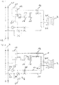
- the device selected as an exemplary embodiment essentially comprises a heating circuit 1 and a cooling circuit 2 connected thereto, which are guided through an injection molding tool 3.
- the injection mold 3 is shown only schematically in the figures, the 31 and the return line 32 connecting, guided within the injection mold 3 heating or cooling channels are not shown.
- the heating circuit 1 comprises a temperature control unit 11, the flow 12 and return 13 are connected to the injection mold 3.
- the temperature control unit 11 is connected via supply lines 7 to the inlet 21 of the cooling circuit 2 or the outlet 42 of the water network 4 (shown in dashed lines in the figures).
- the temperature control unit 1 is formed in a generally known manner and essentially comprises an inner container receptacle of a water reservoir, a pump and a Heater.
- a heater (booster) 14 and a heat condenser 15 are arranged one behind the other in the embodiment. Between heat condenser 15 and injection mold 3, the supply line 12 is connected to the return line 13 via a multiway valve arrangement 16.
- the cooling circuit 2 is connected directly to the inlet 41 and the outlet 42 of a water network.
- a pressure pump 23 is arranged, which ensures the required operating pressure together with the arranged in the return 22 of the cooling circuit 2 spill valve 24.
- the overflow valve 24 promptly a bypass line 6 is arranged in the return line 22 of the cooling circuit 2, which has a shut-off valve 61. Downstream of the pressure pump 23 and the bypass line 6 are inlet 21 and return 22 of the cooling circuit 2 via a multi-way valve assembly 25 connected to each other.
- a throttle valve may be arranged. In the event that - for whatever reason - a bypass line is to be avoided, the bypass functionality - albeit with significantly poor efficiency - can also be achieved by replacing the overflow valve with a solenoid valve. However, this solution is not preferable.
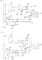
- FIG. 2 the device according to the invention during the heating phase of the injection mold 3 is shown.
- the multi-way valve assembly 16 is set such that the supply line 12 and the return line 13 of the heating circuit 1 are continuous; the two lines are not connected.
- the multi-way valve assembly 25 of the cooling circuit 2 is connected such that the inlet 21 and the return 22 of the cooling circuit 2 are connected and respectively blocked water supply side.
- the heating cycle 1 caused thereby is in FIG. 2 shown in bold lines.
- the T-pieces 311, 321 are connected via the injection molding tool 3 to the heating or cooling circuits 1, 2, a special role. While in FIG. 2 circumscribed in bold heating circuit 1 forms in the thin branches of the tees 311, 321 a standing water column 10 off. A mixing of the hot water of the heating circuit 1 with cold water does not take place.
- FIG. 3 the device according to the invention is shown in the cooling phase.
- the multi-way valve assembly 16 of the heating circuit 1 is connected such that supply 12 and return 13 are connected to each other under decoupling from the temperature control unit 11.
- the multi-way valve arrangement 25 of the cooling circuit 2 is connected in such a way that inlet 21 and return 22 run continuously and separate from one another.
- the cooling circuit thus produced is in FIG. 3 represented by bold lines.
- a standing water column 20 is formed.
- a mixing of the hot water of this standing water column with the cooling circuit 2 shown in bold does not take place.
- the shut-off valve 61 of the bypass line 6 is opened, whereby an increased volume flow and thus an increased cooling capacity is achieved.
- this shut-off valve is closed, which is rebuilt via the pressure pump 23 in conjunction with the spill valve 24 of the required pressure before switching to the heating phase.
- a heat exchanger 81 having a coupling 8 which comprises a arranged in the return line 22 of the cooling circuit 2 check valve 82.
- the shut-off valve 82 When the shut-off valve 82 is closed, the water heated by the heated injection mold 3 flows through the heat exchanger 81, which causes additional water heating in the standby circuit 5.
- the coupling 8 By arranged in the coupling 8 further shut-off valve 83 inadvertent cooling of the heating circuit is avoided when falling below a limit temperature.
Landscapes
- Engineering & Computer Science (AREA)
- Manufacturing & Machinery (AREA)
- Mechanical Engineering (AREA)
- Moulds For Moulding Plastics Or The Like (AREA)
Priority Applications (1)
| Application Number | Priority Date | Filing Date | Title |
|---|---|---|---|
| PL16164667T PL3081361T3 (pl) | 2012-12-03 | 2013-10-28 | Urządzenie do wariotermicznej regulacji temperaturowej narzędzia do odlewania ciśnieniowego |
Applications Claiming Priority (2)
| Application Number | Priority Date | Filing Date | Title |
|---|---|---|---|
| DE102012111700.4A DE102012111700B4 (de) | 2012-12-03 | 2012-12-03 | Vorrichtung und Verfahren zur variothermen Temperierung eines Spritzgießwerkzeugs |
| EP13190485.6A EP2737992B1 (fr) | 2012-12-03 | 2013-10-28 | Procédé destinés à la régulation de température variothermique d'un outil de moulage par injection |
Related Parent Applications (2)
| Application Number | Title | Priority Date | Filing Date |
|---|---|---|---|
| EP13190485.6A Division-Into EP2737992B1 (fr) | 2012-12-03 | 2013-10-28 | Procédé destinés à la régulation de température variothermique d'un outil de moulage par injection |
| EP13190485.6A Division EP2737992B1 (fr) | 2012-12-03 | 2013-10-28 | Procédé destinés à la régulation de température variothermique d'un outil de moulage par injection |
Publications (2)
| Publication Number | Publication Date |
|---|---|
| EP3081361A1 true EP3081361A1 (fr) | 2016-10-19 |
| EP3081361B1 EP3081361B1 (fr) | 2017-10-18 |
Family
ID=49488485
Family Applications (2)
| Application Number | Title | Priority Date | Filing Date |
|---|---|---|---|
| EP16164667.4A Active EP3081361B1 (fr) | 2012-12-03 | 2013-10-28 | Dispositif destine a la regulation de temperature variothermique d'un outil de moulage par injection |
| EP13190485.6A Active EP2737992B1 (fr) | 2012-12-03 | 2013-10-28 | Procédé destinés à la régulation de température variothermique d'un outil de moulage par injection |
Family Applications After (1)
| Application Number | Title | Priority Date | Filing Date |
|---|---|---|---|
| EP13190485.6A Active EP2737992B1 (fr) | 2012-12-03 | 2013-10-28 | Procédé destinés à la régulation de température variothermique d'un outil de moulage par injection |
Country Status (3)
| Country | Link |
|---|---|
| EP (2) | EP3081361B1 (fr) |
| DE (2) | DE102012111700B4 (fr) |
| PL (1) | PL3081361T3 (fr) |
Cited By (1)
| Publication number | Priority date | Publication date | Assignee | Title |
|---|---|---|---|---|
| US20250144851A1 (en) * | 2023-11-08 | 2025-05-08 | Precision Machinery Research & Development Center | High-efficiency mold temperature control system |
Families Citing this family (4)
| Publication number | Priority date | Publication date | Assignee | Title |
|---|---|---|---|---|
| AT516167B1 (de) * | 2015-02-20 | 2016-03-15 | Zizala Lichtsysteme Gmbh | Temperiervorrichtung zum variothermen oder konventionellen Temperieren von Formwerkzeugen |
| AT520890B1 (de) * | 2018-02-01 | 2020-03-15 | Wittmann Kunststoffgeraete | Temperiergerät und Verfahren zum Steuern und Regeln eines Temperiergeräts für ein |
| EP3915754B1 (fr) | 2020-05-26 | 2023-04-19 | Wenz Kunststoff GmbH & Co. KG | Dispositif et procédé de mise en température variothermique d'un outil de moulage par injection |
| DE102022119347A1 (de) | 2021-08-06 | 2023-02-09 | Zechmayer GmbH Werkzeug- und Formenbau | VORRICHTUNG UND VERFAHREN ZUR VARIOTHERMEN TEMPERIERUNG VON SPRITZGIEßWERKZEUGEN |
Citations (3)
| Publication number | Priority date | Publication date | Assignee | Title |
|---|---|---|---|---|
| DE102008045006A1 (de) * | 2008-08-29 | 2010-03-04 | Kraussmaffei Technologies Gmbh | Verfahren und Vorrichtung zur variothermen Temperierung von Spritzgießwerkzeugen |
| JP2012045872A (ja) * | 2010-08-30 | 2012-03-08 | Matsui Mfg Co | 金型温度調節装置 |
| JP2012081595A (ja) * | 2010-10-07 | 2012-04-26 | Matsui Mfg Co | 金型温度調節装置 |
Family Cites Families (5)
| Publication number | Priority date | Publication date | Assignee | Title |
|---|---|---|---|---|
| DE1778068B2 (de) * | 1968-03-25 | 1976-05-06 | Konus-Kessel Gesellschaft für Wärmetechnik mbH & Co KG, 6832 Hockenheim | Vorrichtung zum aufeinanderfolgenden heizen und kuehlen einer bearbeitungseinrichtung |
| US4251479A (en) * | 1979-06-28 | 1981-02-17 | Allied Record Company | Method and apparatus for injection molding data carrying elements |
| JPH1034657A (ja) * | 1996-07-19 | 1998-02-10 | Taiho Kogyo Kk | 成形型の加熱冷却装置 |
| DE10329494B3 (de) * | 2003-06-30 | 2004-07-01 | Technotrans Ag | Temperiervorrichtung für Spritzgiesswerkzeuge |
| JP5069503B2 (ja) * | 2007-06-26 | 2012-11-07 | 三菱重工プラスチックテクノロジー株式会社 | 射出成形システム、コンピュータプログラム、射出成形方法、射出成形機 |
-
2012
- 2012-12-03 DE DE102012111700.4A patent/DE102012111700B4/de active Active
-
2013
- 2013-10-28 DE DE202013104810U patent/DE202013104810U1/de not_active Expired - Lifetime
- 2013-10-28 PL PL16164667T patent/PL3081361T3/pl unknown
- 2013-10-28 EP EP16164667.4A patent/EP3081361B1/fr active Active
- 2013-10-28 EP EP13190485.6A patent/EP2737992B1/fr active Active
Patent Citations (3)
| Publication number | Priority date | Publication date | Assignee | Title |
|---|---|---|---|---|
| DE102008045006A1 (de) * | 2008-08-29 | 2010-03-04 | Kraussmaffei Technologies Gmbh | Verfahren und Vorrichtung zur variothermen Temperierung von Spritzgießwerkzeugen |
| JP2012045872A (ja) * | 2010-08-30 | 2012-03-08 | Matsui Mfg Co | 金型温度調節装置 |
| JP2012081595A (ja) * | 2010-10-07 | 2012-04-26 | Matsui Mfg Co | 金型温度調節装置 |
Cited By (2)
| Publication number | Priority date | Publication date | Assignee | Title |
|---|---|---|---|---|
| US20250144851A1 (en) * | 2023-11-08 | 2025-05-08 | Precision Machinery Research & Development Center | High-efficiency mold temperature control system |
| US12318970B2 (en) * | 2023-11-08 | 2025-06-03 | Precision Machinery Research & Development Center | High-efficiency mold temperature control system |
Also Published As
| Publication number | Publication date |
|---|---|
| PL3081361T3 (pl) | 2018-04-30 |
| DE102012111700B4 (de) | 2017-01-19 |
| EP2737992B1 (fr) | 2016-06-29 |
| EP3081361B1 (fr) | 2017-10-18 |
| DE102012111700A1 (de) | 2014-06-05 |
| DE202013104810U1 (de) | 2013-11-27 |
| EP2737992A1 (fr) | 2014-06-04 |
Similar Documents
| Publication | Publication Date | Title |
|---|---|---|
| DE4210312C2 (de) | Einrichtung zum Auswechseln und wahlweisen Beaufschlagen von einer oder mehreren Formen für die Kunststoffverarbeitung mit einer Flüssigkeit oder einem unter Druck stehenden Gas | |
| DE69114326T2 (de) | Gekühlter Spritzgiessverteilerkanal. | |
| EP2737992B1 (fr) | Procédé destinés à la régulation de température variothermique d'un outil de moulage par injection | |
| DE112009002481B4 (de) | Transportable Steuereinheit für eine Formtemperatur und Verfahren zum Steuern der Temperatur in einer Form | |
| DE2713339A1 (de) | Abkuehlsystem fuer formen | |
| AT516167B1 (de) | Temperiervorrichtung zum variothermen oder konventionellen Temperieren von Formwerkzeugen | |
| DE69913378T2 (de) | Spritzgiesskühlungskern mit rippenkappe | |
| DE202012104680U1 (de) | Vorrichtung zur variothermen Temperierung eines Spritzgießwerkzeugs | |
| DE102008025557B4 (de) | Spritzgießmaschine | |
| EP3915754B1 (fr) | Dispositif et procédé de mise en température variothermique d'un outil de moulage par injection | |
| AT508118B1 (de) | Spritzgiessmaschine | |
| DE2507580A1 (de) | Vorrichtung zum zufuehren fliessfaehigen materials unter druck | |
| DE102013108998B4 (de) | Temperier- und Wärmerückgewinnungssystem für wenigstens eine mit einem Fluid temperierbare Maschine und Verfahren zum Betreiben eines Temperier- und Wärmerückgewinnungssystem | |
| EP0499139B1 (fr) | Dispositif pour admettre un ou plusieurs fluides dans plusieurs moules et pour tempérer les moules pour la transformation des matières plastiques | |
| EP1243394B1 (fr) | Technique de moulage par injection de pièces en matière plastique présentant une partie creuse et appareil de moulage | |
| DE102014007186C5 (de) | Verfahren und Vorrichtung zur Herstellung von Faserverbundbauteilen in einem Reaktionsgießprozess | |
| DE102010000616A1 (de) | Kühlsystem | |
| DE202006020117U1 (de) | Vorrichtung zur Temperierung eines Formwerkzeuges zur Herstellung von Formlingen aus Kunststoff oder Metall | |
| DE102010047953A1 (de) | Anordnung zum Einspritzen von Kunststoff in eine Kavität einer Kunststoffspritzmaschine | |
| DE10329493B3 (de) | Zufuhrvorrichtung für ein Temperiermittel zur Versorgung von Temperiermittelkanälen | |
| DE202011000636U1 (de) | Pumpenmodul zur Verwendung in einem Verteiler für ein Fußbodenheizungssystem | |
| AT505443A2 (de) | Vorrichtung zur entnahme von wärme aus einem wärmeträgerspeicher | |
| DE102023124565A1 (de) | Spritzgießvorrichtung und Spritzgießverfahren zur Herstellung eines Elastomerbauteils sowie Vorwärmaggregat zur Verwendung mit einer Spritzgießvorrichtung | |
| DE102016114706A1 (de) | Adapterplatte sowie Spritzgießmaschine mit einer solchen | |
| DE102023113310A1 (de) | Vorrichtung und Verfahren zur Spritzgießfertigung von Bauteilen |
Legal Events
| Date | Code | Title | Description |
|---|---|---|---|
| PUAI | Public reference made under article 153(3) epc to a published international application that has entered the european phase |
Free format text: ORIGINAL CODE: 0009012 |
|
| AC | Divisional application: reference to earlier application |
Ref document number: 2737992 Country of ref document: EP Kind code of ref document: P |
|
| AK | Designated contracting states |
Kind code of ref document: A1 Designated state(s): AL AT BE BG CH CY CZ DE DK EE ES FI FR GB GR HR HU IE IS IT LI LT LU LV MC MK MT NL NO PL PT RO RS SE SI SK SM TR |
|
| 17P | Request for examination filed |
Effective date: 20161021 |
|
| RBV | Designated contracting states (corrected) |
Designated state(s): AL AT BE BG CH CY CZ DE DK EE ES FI FR GB GR HR HU IE IS IT LI LT LU LV MC MK MT NL NO PL PT RO RS SE SI SK SM TR |
|
| REG | Reference to a national code |
Ref country code: DE Ref legal event code: R079 Ref document number: 502013008626 Country of ref document: DE Free format text: PREVIOUS MAIN CLASS: B29C0045160000 Ipc: B29C0045730000 |
|
| GRAP | Despatch of communication of intention to grant a patent |
Free format text: ORIGINAL CODE: EPIDOSNIGR1 |
|
| RIC1 | Information provided on ipc code assigned before grant |
Ipc: B29C 45/73 20060101AFI20170620BHEP |
|
| INTG | Intention to grant announced |
Effective date: 20170711 |
|
| GRAS | Grant fee paid |
Free format text: ORIGINAL CODE: EPIDOSNIGR3 |
|
| GRAA | (expected) grant |
Free format text: ORIGINAL CODE: 0009210 |
|
| AC | Divisional application: reference to earlier application |
Ref document number: 2737992 Country of ref document: EP Kind code of ref document: P |
|
| AK | Designated contracting states |
Kind code of ref document: B1 Designated state(s): AL AT BE BG CH CY CZ DE DK EE ES FI FR GB GR HR HU IE IS IT LI LT LU LV MC MK MT NL NO PL PT RO RS SE SI SK SM TR |
|
| REG | Reference to a national code |
Ref country code: GB Ref legal event code: FG4D Free format text: NOT ENGLISH |
|
| REG | Reference to a national code |
Ref country code: CH Ref legal event code: EP |
|
| REG | Reference to a national code |
Ref country code: AT Ref legal event code: REF Ref document number: 937553 Country of ref document: AT Kind code of ref document: T Effective date: 20171115 Ref country code: IE Ref legal event code: FG4D Free format text: LANGUAGE OF EP DOCUMENT: GERMAN |
|
| REG | Reference to a national code |
Ref country code: FR Ref legal event code: PLFP Year of fee payment: 5 |
|
| REG | Reference to a national code |
Ref country code: DE Ref legal event code: R096 Ref document number: 502013008626 Country of ref document: DE |
|
| REG | Reference to a national code |
Ref country code: CH Ref legal event code: NV Representative=s name: DR.-ING. ULRICH KOETTER, CH |
|
| REG | Reference to a national code |
Ref country code: NL Ref legal event code: FP |
|
| REG | Reference to a national code |
Ref country code: LT Ref legal event code: MG4D |
|
| PG25 | Lapsed in a contracting state [announced via postgrant information from national office to epo] |
Ref country code: ES Free format text: LAPSE BECAUSE OF FAILURE TO SUBMIT A TRANSLATION OF THE DESCRIPTION OR TO PAY THE FEE WITHIN THE PRESCRIBED TIME-LIMIT Effective date: 20171018 Ref country code: LT Free format text: LAPSE BECAUSE OF FAILURE TO SUBMIT A TRANSLATION OF THE DESCRIPTION OR TO PAY THE FEE WITHIN THE PRESCRIBED TIME-LIMIT Effective date: 20171018 Ref country code: SE Free format text: LAPSE BECAUSE OF FAILURE TO SUBMIT A TRANSLATION OF THE DESCRIPTION OR TO PAY THE FEE WITHIN THE PRESCRIBED TIME-LIMIT Effective date: 20171018 Ref country code: FI Free format text: LAPSE BECAUSE OF FAILURE TO SUBMIT A TRANSLATION OF THE DESCRIPTION OR TO PAY THE FEE WITHIN THE PRESCRIBED TIME-LIMIT Effective date: 20171018 Ref country code: NO Free format text: LAPSE BECAUSE OF FAILURE TO SUBMIT A TRANSLATION OF THE DESCRIPTION OR TO PAY THE FEE WITHIN THE PRESCRIBED TIME-LIMIT Effective date: 20180118 |
|
| PG25 | Lapsed in a contracting state [announced via postgrant information from national office to epo] |
Ref country code: GR Free format text: LAPSE BECAUSE OF FAILURE TO SUBMIT A TRANSLATION OF THE DESCRIPTION OR TO PAY THE FEE WITHIN THE PRESCRIBED TIME-LIMIT Effective date: 20180119 Ref country code: HR Free format text: LAPSE BECAUSE OF FAILURE TO SUBMIT A TRANSLATION OF THE DESCRIPTION OR TO PAY THE FEE WITHIN THE PRESCRIBED TIME-LIMIT Effective date: 20171018 Ref country code: LV Free format text: LAPSE BECAUSE OF FAILURE TO SUBMIT A TRANSLATION OF THE DESCRIPTION OR TO PAY THE FEE WITHIN THE PRESCRIBED TIME-LIMIT Effective date: 20171018 Ref country code: RS Free format text: LAPSE BECAUSE OF FAILURE TO SUBMIT A TRANSLATION OF THE DESCRIPTION OR TO PAY THE FEE WITHIN THE PRESCRIBED TIME-LIMIT Effective date: 20171018 Ref country code: BG Free format text: LAPSE BECAUSE OF FAILURE TO SUBMIT A TRANSLATION OF THE DESCRIPTION OR TO PAY THE FEE WITHIN THE PRESCRIBED TIME-LIMIT Effective date: 20180118 Ref country code: IS Free format text: LAPSE BECAUSE OF FAILURE TO SUBMIT A TRANSLATION OF THE DESCRIPTION OR TO PAY THE FEE WITHIN THE PRESCRIBED TIME-LIMIT Effective date: 20180218 |
|
| REG | Reference to a national code |
Ref country code: DE Ref legal event code: R097 Ref document number: 502013008626 Country of ref document: DE |
|
| REG | Reference to a national code |
Ref country code: IE Ref legal event code: MM4A |
|
| PG25 | Lapsed in a contracting state [announced via postgrant information from national office to epo] |
Ref country code: EE Free format text: LAPSE BECAUSE OF FAILURE TO SUBMIT A TRANSLATION OF THE DESCRIPTION OR TO PAY THE FEE WITHIN THE PRESCRIBED TIME-LIMIT Effective date: 20171018 Ref country code: CZ Free format text: LAPSE BECAUSE OF FAILURE TO SUBMIT A TRANSLATION OF THE DESCRIPTION OR TO PAY THE FEE WITHIN THE PRESCRIBED TIME-LIMIT Effective date: 20171018 Ref country code: LU Free format text: LAPSE BECAUSE OF NON-PAYMENT OF DUE FEES Effective date: 20171028 Ref country code: DK Free format text: LAPSE BECAUSE OF FAILURE TO SUBMIT A TRANSLATION OF THE DESCRIPTION OR TO PAY THE FEE WITHIN THE PRESCRIBED TIME-LIMIT Effective date: 20171018 Ref country code: SK Free format text: LAPSE BECAUSE OF FAILURE TO SUBMIT A TRANSLATION OF THE DESCRIPTION OR TO PAY THE FEE WITHIN THE PRESCRIBED TIME-LIMIT Effective date: 20171018 Ref country code: MC Free format text: LAPSE BECAUSE OF FAILURE TO SUBMIT A TRANSLATION OF THE DESCRIPTION OR TO PAY THE FEE WITHIN THE PRESCRIBED TIME-LIMIT Effective date: 20171018 |
|
| PLBE | No opposition filed within time limit |
Free format text: ORIGINAL CODE: 0009261 |
|
| STAA | Information on the status of an ep patent application or granted ep patent |
Free format text: STATUS: NO OPPOSITION FILED WITHIN TIME LIMIT |
|
| PG25 | Lapsed in a contracting state [announced via postgrant information from national office to epo] |
Ref country code: SM Free format text: LAPSE BECAUSE OF FAILURE TO SUBMIT A TRANSLATION OF THE DESCRIPTION OR TO PAY THE FEE WITHIN THE PRESCRIBED TIME-LIMIT Effective date: 20171018 Ref country code: IT Free format text: LAPSE BECAUSE OF FAILURE TO SUBMIT A TRANSLATION OF THE DESCRIPTION OR TO PAY THE FEE WITHIN THE PRESCRIBED TIME-LIMIT Effective date: 20171018 |
|
| 26N | No opposition filed |
Effective date: 20180719 |
|
| PG25 | Lapsed in a contracting state [announced via postgrant information from national office to epo] |
Ref country code: MT Free format text: LAPSE BECAUSE OF FAILURE TO SUBMIT A TRANSLATION OF THE DESCRIPTION OR TO PAY THE FEE WITHIN THE PRESCRIBED TIME-LIMIT Effective date: 20171018 |
|
| REG | Reference to a national code |
Ref country code: FR Ref legal event code: PLFP Year of fee payment: 6 |
|
| PG25 | Lapsed in a contracting state [announced via postgrant information from national office to epo] |
Ref country code: IE Free format text: LAPSE BECAUSE OF NON-PAYMENT OF DUE FEES Effective date: 20171028 |
|
| PG25 | Lapsed in a contracting state [announced via postgrant information from national office to epo] |
Ref country code: SI Free format text: LAPSE BECAUSE OF FAILURE TO SUBMIT A TRANSLATION OF THE DESCRIPTION OR TO PAY THE FEE WITHIN THE PRESCRIBED TIME-LIMIT Effective date: 20171018 |
|
| REG | Reference to a national code |
Ref country code: DE Ref legal event code: R082 Ref document number: 502013008626 Country of ref document: DE Representative=s name: PATENTANWAELTE DOERNER & KOETTER PARTG MBB, DE Ref country code: DE Ref legal event code: R081 Ref document number: 502013008626 Country of ref document: DE Owner name: WELLER, KARSTEN, DE Free format text: FORMER OWNER: WENZ KUNSTSTOFF GMBH & CO. KG, 58511 LUEDENSCHEID, DE |
|
| REG | Reference to a national code |
Ref country code: CH Ref legal event code: PUE Owner name: KARSTEN WELLER, DE Free format text: FORMER OWNER: WENZ KUNSTSTOFF GMBH AND CO. KG, DE |
|
| REG | Reference to a national code |
Ref country code: GB Ref legal event code: 732E Free format text: REGISTERED BETWEEN 20181213 AND 20181219 |
|
| REG | Reference to a national code |
Ref country code: BE Ref legal event code: PD Owner name: WELLER, KARSTEN; DE Free format text: DETAILS ASSIGNMENT: CHANGE OF OWNER(S), CESSION; FORMER OWNER NAME: WENZ KUNSTSTOFF GMBH & CO. KG Effective date: 20181217 |
|
| REG | Reference to a national code |
Ref country code: AT Ref legal event code: PC Ref document number: 937553 Country of ref document: AT Kind code of ref document: T Owner name: KARSTEN WELLER, DE Effective date: 20190304 |
|
| REG | Reference to a national code |
Ref country code: NL Ref legal event code: PD Owner name: KARSTEN WELLER; DE Free format text: DETAILS ASSIGNMENT: CHANGE OF OWNER(S), ASSIGNMENT; FORMER OWNER NAME: WENZ KUNSTSTOFF GMBH & CO. KG Effective date: 20190225 |
|
| PG25 | Lapsed in a contracting state [announced via postgrant information from national office to epo] |
Ref country code: HU Free format text: LAPSE BECAUSE OF FAILURE TO SUBMIT A TRANSLATION OF THE DESCRIPTION OR TO PAY THE FEE WITHIN THE PRESCRIBED TIME-LIMIT; INVALID AB INITIO Effective date: 20131028 |
|
| PG25 | Lapsed in a contracting state [announced via postgrant information from national office to epo] |
Ref country code: RO Free format text: LAPSE BECAUSE OF FAILURE TO SUBMIT A TRANSLATION OF THE DESCRIPTION OR TO PAY THE FEE WITHIN THE PRESCRIBED TIME-LIMIT Effective date: 20171018 |
|
| PG25 | Lapsed in a contracting state [announced via postgrant information from national office to epo] |
Ref country code: CY Free format text: LAPSE BECAUSE OF FAILURE TO SUBMIT A TRANSLATION OF THE DESCRIPTION OR TO PAY THE FEE WITHIN THE PRESCRIBED TIME-LIMIT Effective date: 20171018 |
|
| PG25 | Lapsed in a contracting state [announced via postgrant information from national office to epo] |
Ref country code: MK Free format text: LAPSE BECAUSE OF FAILURE TO SUBMIT A TRANSLATION OF THE DESCRIPTION OR TO PAY THE FEE WITHIN THE PRESCRIBED TIME-LIMIT Effective date: 20171018 |
|
| PG25 | Lapsed in a contracting state [announced via postgrant information from national office to epo] |
Ref country code: PT Free format text: LAPSE BECAUSE OF FAILURE TO SUBMIT A TRANSLATION OF THE DESCRIPTION OR TO PAY THE FEE WITHIN THE PRESCRIBED TIME-LIMIT Effective date: 20171018 |
|
| PG25 | Lapsed in a contracting state [announced via postgrant information from national office to epo] |
Ref country code: AL Free format text: LAPSE BECAUSE OF FAILURE TO SUBMIT A TRANSLATION OF THE DESCRIPTION OR TO PAY THE FEE WITHIN THE PRESCRIBED TIME-LIMIT Effective date: 20171018 |
|
| P01 | Opt-out of the competence of the unified patent court (upc) registered |
Effective date: 20230422 |
|
| REG | Reference to a national code |
Ref country code: CH Ref legal event code: U11 Free format text: ST27 STATUS EVENT CODE: U-0-0-U10-U11 (AS PROVIDED BY THE NATIONAL OFFICE) Effective date: 20251101 |
|
| PGFP | Annual fee paid to national office [announced via postgrant information from national office to epo] |
Ref country code: NL Payment date: 20251023 Year of fee payment: 13 |
|
| PGFP | Annual fee paid to national office [announced via postgrant information from national office to epo] |
Ref country code: DE Payment date: 20251015 Year of fee payment: 13 |
|
| PGFP | Annual fee paid to national office [announced via postgrant information from national office to epo] |
Ref country code: GB Payment date: 20251024 Year of fee payment: 13 |
|
| PGFP | Annual fee paid to national office [announced via postgrant information from national office to epo] |
Ref country code: AT Payment date: 20251021 Year of fee payment: 13 |
|
| PGFP | Annual fee paid to national office [announced via postgrant information from national office to epo] |
Ref country code: FR Payment date: 20251024 Year of fee payment: 13 |
|
| PGFP | Annual fee paid to national office [announced via postgrant information from national office to epo] |
Ref country code: TR Payment date: 20251122 Year of fee payment: 13 Ref country code: BE Payment date: 20251022 Year of fee payment: 13 |
|
| PGFP | Annual fee paid to national office [announced via postgrant information from national office to epo] |
Ref country code: CH Payment date: 20251101 Year of fee payment: 13 |
|
| PGFP | Annual fee paid to national office [announced via postgrant information from national office to epo] |
Ref country code: PL Payment date: 20251020 Year of fee payment: 13 |