EP3081412B1 - Dispositif de réglage de direction d'écoulement d'air - Google Patents
Dispositif de réglage de direction d'écoulement d'air Download PDFInfo
- Publication number
- EP3081412B1 EP3081412B1 EP14870499.2A EP14870499A EP3081412B1 EP 3081412 B1 EP3081412 B1 EP 3081412B1 EP 14870499 A EP14870499 A EP 14870499A EP 3081412 B1 EP3081412 B1 EP 3081412B1
- Authority
- EP
- European Patent Office
- Prior art keywords
- fin
- fins
- knob
- shaft
- blowing mode
- Prior art date
- Legal status (The legal status is an assumption and is not a legal conclusion. Google has not performed a legal analysis and makes no representation as to the accuracy of the status listed.)
- Active
Links
Images






Classifications
-
- B—PERFORMING OPERATIONS; TRANSPORTING
- B60—VEHICLES IN GENERAL
- B60H—ARRANGEMENTS OF HEATING, COOLING, VENTILATING OR OTHER AIR-TREATING DEVICES SPECIALLY ADAPTED FOR PASSENGER OR GOODS SPACES OF VEHICLES
- B60H1/00—Heating, cooling or ventilating devices
- B60H1/34—Nozzles; Air-diffusers
-
- F—MECHANICAL ENGINEERING; LIGHTING; HEATING; WEAPONS; BLASTING
- F24—HEATING; RANGES; VENTILATING
- F24F—AIR-CONDITIONING; AIR-HUMIDIFICATION; VENTILATION; USE OF AIR CURRENTS FOR SCREENING
- F24F13/00—Details common to, or for air-conditioning, air-humidification, ventilation or use of air currents for screening
- F24F13/08—Air-flow control members, e.g. louvres, grilles, flaps or guide plates
- F24F13/10—Air-flow control members, e.g. louvres, grilles, flaps or guide plates movable, e.g. dampers
- F24F13/14—Air-flow control members, e.g. louvres, grilles, flaps or guide plates movable, e.g. dampers built up of tilting members, e.g. louvre
- F24F13/15—Air-flow control members, e.g. louvres, grilles, flaps or guide plates movable, e.g. dampers built up of tilting members, e.g. louvre with parallel simultaneously tiltable lamellae
-
- B—PERFORMING OPERATIONS; TRANSPORTING
- B60—VEHICLES IN GENERAL
- B60H—ARRANGEMENTS OF HEATING, COOLING, VENTILATING OR OTHER AIR-TREATING DEVICES SPECIALLY ADAPTED FOR PASSENGER OR GOODS SPACES OF VEHICLES
- B60H1/00—Heating, cooling or ventilating devices
- B60H1/00642—Control systems or circuits; Control members or indication devices for heating, cooling or ventilating devices
- B60H1/00814—Control systems or circuits characterised by their output, for controlling particular components of the heating, cooling or ventilating installation
- B60H1/00821—Control systems or circuits characterised by their output, for controlling particular components of the heating, cooling or ventilating installation the components being ventilating, air admitting or air distributing devices
- B60H1/00871—Air directing means, e.g. blades in an air outlet
-
- B—PERFORMING OPERATIONS; TRANSPORTING
- B60—VEHICLES IN GENERAL
- B60H—ARRANGEMENTS OF HEATING, COOLING, VENTILATING OR OTHER AIR-TREATING DEVICES SPECIALLY ADAPTED FOR PASSENGER OR GOODS SPACES OF VEHICLES
- B60H1/00—Heating, cooling or ventilating devices
- B60H1/34—Nozzles; Air-diffusers
- B60H1/3407—Nozzles; Air-diffusers providing an air stream in a fixed direction, e.g. using a grid or porous panel
-
- B—PERFORMING OPERATIONS; TRANSPORTING
- B60—VEHICLES IN GENERAL
- B60H—ARRANGEMENTS OF HEATING, COOLING, VENTILATING OR OTHER AIR-TREATING DEVICES SPECIALLY ADAPTED FOR PASSENGER OR GOODS SPACES OF VEHICLES
- B60H1/00—Heating, cooling or ventilating devices
- B60H1/34—Nozzles; Air-diffusers
- B60H1/3414—Nozzles; Air-diffusers with means for adjusting the air stream direction
-
- B—PERFORMING OPERATIONS; TRANSPORTING
- B60—VEHICLES IN GENERAL
- B60H—ARRANGEMENTS OF HEATING, COOLING, VENTILATING OR OTHER AIR-TREATING DEVICES SPECIALLY ADAPTED FOR PASSENGER OR GOODS SPACES OF VEHICLES
- B60H1/00—Heating, cooling or ventilating devices
- B60H1/34—Nozzles; Air-diffusers
- B60H1/3414—Nozzles; Air-diffusers with means for adjusting the air stream direction
- B60H1/3421—Nozzles; Air-diffusers with means for adjusting the air stream direction using only pivoting shutters
-
- B—PERFORMING OPERATIONS; TRANSPORTING
- B60—VEHICLES IN GENERAL
- B60H—ARRANGEMENTS OF HEATING, COOLING, VENTILATING OR OTHER AIR-TREATING DEVICES SPECIALLY ADAPTED FOR PASSENGER OR GOODS SPACES OF VEHICLES
- B60H1/00—Heating, cooling or ventilating devices
- B60H1/34—Nozzles; Air-diffusers
- B60H1/345—Nozzles; Air-diffusers with means for adjusting divergence, convergence or oscillation of air stream
-
- F—MECHANICAL ENGINEERING; LIGHTING; HEATING; WEAPONS; BLASTING
- F24—HEATING; RANGES; VENTILATING
- F24F—AIR-CONDITIONING; AIR-HUMIDIFICATION; VENTILATION; USE OF AIR CURRENTS FOR SCREENING
- F24F13/00—Details common to, or for air-conditioning, air-humidification, ventilation or use of air currents for screening
- F24F13/02—Ducting arrangements
- F24F13/06—Outlets for directing or distributing air into rooms or spaces, e.g. ceiling air diffuser
-
- F—MECHANICAL ENGINEERING; LIGHTING; HEATING; WEAPONS; BLASTING
- F24—HEATING; RANGES; VENTILATING
- F24F—AIR-CONDITIONING; AIR-HUMIDIFICATION; VENTILATION; USE OF AIR CURRENTS FOR SCREENING
- F24F13/00—Details common to, or for air-conditioning, air-humidification, ventilation or use of air currents for screening
- F24F13/02—Ducting arrangements
- F24F13/06—Outlets for directing or distributing air into rooms or spaces, e.g. ceiling air diffuser
- F24F13/075—Outlets for directing or distributing air into rooms or spaces, e.g. ceiling air diffuser having parallel rods or lamellae directing the outflow, e.g. the rods or lamellae being individually adjustable
-
- F—MECHANICAL ENGINEERING; LIGHTING; HEATING; WEAPONS; BLASTING
- F24—HEATING; RANGES; VENTILATING
- F24F—AIR-CONDITIONING; AIR-HUMIDIFICATION; VENTILATION; USE OF AIR CURRENTS FOR SCREENING
- F24F13/00—Details common to, or for air-conditioning, air-humidification, ventilation or use of air currents for screening
- F24F13/08—Air-flow control members, e.g. louvres, grilles, flaps or guide plates
- F24F13/10—Air-flow control members, e.g. louvres, grilles, flaps or guide plates movable, e.g. dampers
- F24F13/14—Air-flow control members, e.g. louvres, grilles, flaps or guide plates movable, e.g. dampers built up of tilting members, e.g. louvre
- F24F13/1426—Air-flow control members, e.g. louvres, grilles, flaps or guide plates movable, e.g. dampers built up of tilting members, e.g. louvre characterised by actuating means
-
- B—PERFORMING OPERATIONS; TRANSPORTING
- B60—VEHICLES IN GENERAL
- B60H—ARRANGEMENTS OF HEATING, COOLING, VENTILATING OR OTHER AIR-TREATING DEVICES SPECIALLY ADAPTED FOR PASSENGER OR GOODS SPACES OF VEHICLES
- B60H1/00—Heating, cooling or ventilating devices
- B60H1/34—Nozzles; Air-diffusers
- B60H2001/3471—Details of actuators
Definitions
- the present invention relates to an airflow-direction adjustment device varying a flow of air toward a front-side opening portion through a fin in a cooling and heating equipment, air conditioning equipment, or the like, and especially varying the fin through a link mechanism, with the features of the preamble of claim 1.
- FR 2 710 879 A1 discloses a conventional airflow-direction adjustment device wherein the front horizontal vane supporting the knob is pushed forward, thereby pushing also the rear vertical vane forward.
- US 5 364 303 A discloses an airflow-direction adjustment device wherein a knob is supported by vanes intended to be moved in a scattered mode.
- Figs. 16(a) and 16(b) show an airflow-direction adjustment device for a vehicle disclosed in Fig. 1 and Fig. 2 of JP2002-277040 .
- the structure comprises a case (frame) 10 set in such a way as to blow out air to outside from a front-side opening portion; five fins 12, 14, 16, 18, and 20 disposed approximately in parallel relative to an opposed support portion (second connection element) 44 inside the case 10, and located on right and left side faces wherein one end side in a plate width direction is pivotally supported turnably through pins 42 respectively; a link mechanism associating four fins 12, 14, 18, and 20 among the aforementioned fins to move; a button 54 and an operation element 52 as a switch linked to the link mechanism; and the like.
- the aforementioned structure can adjustably switch between a parallel air-blowing mode in Fig. 16(a) wherein the aforementioned fins become approximately parallel to each other, and a scattered air-blowing mode in Fig. 16(b) wherein among the aforementioned fins, the first fins 14 and 18 sandwiching the intermediate fin 16, and the second fins 12 and 20 are turned in the directions opposite to each other.
- the link mechanism is interposed between a first connection element 24 disposed movably forward against an urging force of a return spring 40, and each fin 12, 14, 16, 18, and 20.
- the link mechanism is formed by pins 22 located on one side face of each fin and provided approximately in a middle in the plate width direction; and slot-shaped links 26, 28, 30, 32, and 34 provided in the first connection element 24 and fitting into the pins 22.
- the links 26 and 28, and the links 32 and 34 are formed in arc grooves inclined in the directions opposite to each other. Then, in order to switch from the parallel air-blowing mode in Fig. 16(a) to the scattered air-blowing mode in Fig.
- each fin 12, 14, 16, 18, and 20 is guided in a groove shape of the links 26, 28, 30, 32, and 34 wherein each pin 22 corresponds so as to be switched to the scattered air-blowing mode.
- the latch mechanism 56 releases the push button, so that the first connection element 24 is returned to the original position by the urging force of the spring 40, and each fin is guided by the links 26, 28, 30, 32, and 34 wherein each pin 22 corresponds so as to be switched to the parallel air-blowing mode.
- JP2002-277040 in the aforementioned structure, there are disclosed two modified examples wherein the aforementioned link mechanism is modified. Among those, in the link mechanism disclosed in Fig. 3 and Fig. 4 in JP2002-277040 (not shown in the drawings), the fins 12 and 14 on a lower side are turnably connected relative to the first connection element 24 through each arm pivotally supported by common pins 62; the fins 18 and 20 on an upper side are turnably connected relative to the first connection element 24 through each arm pivotally supported by the common pins 62; and the intermediate fin 16 is fitted into the slot-shaped link 30 provided in the first connection element 24 through the pin 22.
- the fins 12 and 14 on the lower side are turnably connected relative to the first connection element 24 through links 60 and 70; the fins 18 and 20 on the upper side are turnably connected relative to the first connection element 24 through the links 60 and 70; and the intermediate fin 16 having two structures is connected by the link, and fitted into the slot-shaped link 30 provided in the first connection element 24 through the pin 22.
- each fin includes the relatively large first connection element which is connected through the link mechanism, and the first connection element is movably incorporated relative to the frame. Also, there are required the button and the operation element moving the first connection element forward against the urging force of the spring; and further the latch mechanism maintaining the state after the movement as well. As a result, the structure of the aforementioned JP2002-277040 becomes complicated so as to be difficult to obtain reduction in weight as well.
- the link mechanism has the structure of connecting the first connection element and each fin in any structure, and in a case of forming a plurality of slot-shaped links in the first connection element in Fig. 1 and Fig. 2 of JP2002-277040 , an excellent operation is difficult to be maintained, and in cases of the structure in Fig. 3 and Fig. 4 of JP2002-277040 , and the structure in Fig. 5 and Fig. 6 of JP2002-277040 , there are many dedicated links in addition to the first connection element so as to become complicated and increase weight as well.
- An object of the present invention is to solve the aforementioned problems, and easily obtain a simplified structure and the reduction in weight as well as excellence in an airflow-direction adjustment.
- Other objects of the present invention will be clarified in the following explanation of contents.
- the present invention provides an airflow-direction adjustment device with the features of claim 1.
- the parallel air-blowing mode and the scattered air-blowing mode can be switched by operating the knob to move forward and backward, and the parallel air-blowing mode and the inclined air-blowing mode can be switched by operating the knob to move horizontally so as to provide various air-blowing modes with fewer parts.
- the structure comprising the link mechanism associating two or more fins among the plurality of fins; and the operating knob so as to adjustably switch between the parallel air-blowing mode wherein the fins become approximately parallel to each other, and the scattered air-blowing mode wherein the two or more fins are turned in the directions opposite to each other, can be carried out by the structure of connecting the knob to the intermediate fin; and the structure of two first links turnably connecting respectively one end side corresponding to the first fins disposed on both adjacent sides of the intermediate fin, and turnably connecting respectively the corresponding other end side to the intermediate fin as the link mechanism.
- the single knob connected to the intermediate fin, the intermediate fin, and the fins on both adjacent sides of the intermediate fin can be connected by the two links forming the link mechanism so as to be carried out with a total of three members.
- Figs. 1(a) and 1(b) schematically show an airflow-direction adjustment device according to a first embodiment which does not form part of the invention but is useful for understanding the invention, wherein Fig. 1(a) is an external view in a parallel air-blowing mode state; and Fig. 1(b) is an external view in a scattered air-blowing mode state.
- an airflow-direction adjustment device 1 of the first embodiment comprises a case 2 set in such a way as to blow out air to an outside from an inside; a plurality (in the embodiment, five pieces) of horizontal-type fins 30 to 34 (3) disposed approximately in parallel relative to bearing brackets 7A and 7B (7) facing on right and left near a front-side opening inside the case 2, and located on right and left side faces 30a to 34a and 30b to 34b (see Fig.
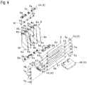
- a link mechanism 4 associating two or more fins; a switch 5 linked to the link mechanism 4; a plurality (in the embodiment, five pieces) of vertical-type fins 6A to 6E (6) disposed approximately in parallel relative to bearing brackets 9A and 9B (9) facing on top and bottom on a deep side of the front-side opening inside the case 2, and located on top and bottom side faces wherein an approximately middle is pivotally supported turnably; a connection member 9C (see Fig. 4 ) associating the fins 6A to 6E; and an operating operation member 8.
- the vertical-type fins 6 can adjustably switch an airflow direction by turning each fin 6A to 6E to right and left only at a predetermined angle through the operation member 8.
- the horizontal-type fin 3 can adjustably switch between a parallel air-blowing mode wherein each fin 30 to 34 becomes approximately parallel to each other; and a scattered air-blowing mode wherein two or more fins (in the embodiment, the fins 31 and 33 which are first fins, and the fins 30 and 34 which are second fins, and in an embodiment wherein the fins 3 have a three-piece structure, the fins 31 and 33 which are the first fins) are turned in directions opposite to each other, through the switch 5.
- the switch 5 is assembled movably to the intermediate fin 32 disposed in a middle among the plurality of fins 3;
- the link mechanism 4 includes two first links 41 and 42 turnably connecting respectively one end 42a and 41a sides (see Fig. 9(b) ) corresponding to the other end sides in a plate width direction of the first fins 31 and 33 disposed on both adjacent sides of the intermediate fin 32, and turnably connecting respectively the corresponding other end 42b and 41b sides (see Fig.
- the link mechanism 4 includes two second links 40 and 43 for associating or synchronizing the second fins 30 and 34 disposed on sides opposite to the intermediate fin 32 among both adjacent sides of the first fins 31 and 33, and the fin 30 with the first fin 31, and the fin 34 with the first fin 33 as the plurality of fins 3.
- the link mechanism 4 includes two second links 40 and 43 for associating or synchronizing the second fins 30 and 34 disposed on sides opposite to the intermediate fin 32 among both adjacent sides of the first fins 31 and 33, and the fin 30 with the first fin 31, and the fin 34 with the first fin 33 as the plurality of fins 3.
- a main member 20 and a front frame 25 forming the case 2; each fin 30 to 34 forming the horizontal-type fin 3; each link 40 to 44 forming the link mechanism 4; the operating switch 5; each fin 6A to 6E forming the vertical-type fins 6; a knob 8A and a base 8B forming the operation member 8; the brackets 7 and 9 or each bracket 7A, 7B, 9A, and 9B; and the connection member 9C, are all resin articles; however, they may be made of materials other than resin.
- the case 2 is formed to divide an inner space 24 in a state wherein the front frame 25 which is a decorative frame is mounted on a front side of the main member 20.
- the main member 20 includes engagement portions 21a and 21b provided on a back portion side; positioning portions 22a and 22b provided on front and back portions; attachment portions 23; and the like, which are located on an outer face, to be mounted on an installation portion of a vehicle and the like using those portions.
- the inner space 24 opens in a front-and-back direction, and a front frame 25 side is set as an air outlet, and a back end side is set as an air inlet.
- the front frame 25 includes a flange portion 26 integrated around a frame, and is mounted on the main member 20 through an engagement hole 27, engagement piece portions 28a and 28b, and the like provided on the flange portion 26.
- brackets 9A and 9B for the vertical-type fins are mounted on an inner face of the top and bottom of the main member; and the brackets 7A and 7B for the horizontal-type fin are mounted on an inside face of the right and left of the main member.
- the brackets 9A and 9B have five shaft holes 9a facing each other.
- the fins 6A to 6E include shaft portions 6a respectively protruding on upper and lower end portions, and are turnably supported in a state wherein each shaft portion 6a thereof is fitted into the corresponding shaft hole 9a relative to the brackets 9A and 9B.
- each fin 6A to 6E includes shaft portions 6b provided in a step portion on an upper end side, and disposed on one step lower side than the shaft portions 6a, and the shaft portions 6b are turnably fitted respectively into corresponding shaft holes 9b provided in the arm-shaped connection member 9C. Consequently, in each fin 6A to 6E, in a state assembled to the operation member 8, i.e. the base 8B mounted on the intermediate fin 6C, and the later-described intermediate fin 32 slidably to the right and left, when the fins 6A to 6E are moved to the right and left through the knob 8A connected to the base 8B, all fins 6A to 6E are integrally associated through the connection member 9C.
- the brackets 7A and 7B have five shaft holes 7a facing each other.
- the fins 30 to 34 include shaft portions 35a to 39a respectively protruding on each side face of the right end portions 30a to 34a and the left end portions 30b to 34b, and in a state wherein each shaft portion 35a to 39a is fitted into the corresponding shaft hole 7a relative to the brackets 7A and 7B, the fins 30 to 34 are disposed approximately in parallel between the same brackets, and turnably supported.
- each fin 30 to 34 includes notch portions 30c to 34c provided in the left end portions 30b to 34b.
- notch portions 30c to 34c in the notch portions 30c and 31c, and the notch portions 33c and 34c, there are provided shaft portions 35b and 36b, and shaft portions 38b and 39b which are approximately in parallel to the shaft portions 35a and 36a, and the shaft portions 38a and 39a, and slightly smaller.
- the notch portion 32c of the intermediate fin 32 is formed larger compared to the notch portions 30c, 31c, 33c, and 34c, and is not provided with a shaft portion corresponding to the shaft portions 35b, 36b, 38b, and 39b.
- the notch portion 32c is used as a portion to movably dispose the end portions 41b and 42b corresponding to the later-described first links 41 and 42 (and the connection portion 51 of the switch 5 connecting to the end portions 41b and 42b).
- the intermediate fin 32 includes a concave portion 32d located at the left end portion 32b and provided at a periphery portion corresponding to the notch portion 32c; and a guide groove 32e located in a middle portion of right and left and provided at one side close to a line connecting the shaft portions 37a on both sides; and a guide groove 32f provided on the other side and facing the guide groove 32e.
- the concave portion 32d forms a guide device by fitting into convex portions 56 (see Fig. 9(d) ) on a switch 5 side when the later-described switch 5 slides in a front-and-back direction.
- the guide grooves 32e and 32f are used for assembling the knob 8A in Fig. 4 slidably in a right-and-left direction only for a predetermined distance.
- the knob 8A is connected to the aforementioned base 8B in a state assembled to the intermediate fin 32 through the guide grooves 32e and 32f.
- the aforementioned link mechanism 4 includes a total of four links of the first links 41 and 42, and the second links 40 and 43.
- the link mechanism 4 with respect to the embodiment, if a device structure has three fins 31 to 33, the second links 40 and 43 are to be omitted, and contrarily, if the device structure has seven fins, two more links are to be added.
- the lowermost link 40 is the first link, and includes a shaft hole 45a provided in one end portion 40a, and a shaft hole 45b provided in a step portion of the other end portion 40b.
- the link 41 is the second link, and includes a shaft hole 46a provided in one end portion 41a and communicated with the shaft hole 45b; and a shaft portion 49b provided in a step portion of the other end portion 41b.
- the link 42 is the third link, and includes a shaft hole 47a provided in one end portion 42a; and a shaft portion 49a provided in a step portion of the other end portion 42b, and disposed back to back with the shaft portion 49b.
- the uppermost link 43 is the fourth link, and includes a shaft hole 48a provided in one end portion 43a; and a shaft hole 48b provided in a step portion of the other end portion 41b, and communicated with the shaft hole 47a.
- the fins 31 and 33 can adjustably switch between the parallel air-blowing mode disposed approximately in parallel to the intermediate fin 32; and the scattered air-blowing mode turned in the opposite directions through the switch 5.
- the shaft portion 36b of the fin 31 forming the first fin is turnably fitted into the shaft holes 45a and 46a; the shaft portion 38b of the fin 33 forming the first fin is turnably fitted into the shaft holes 48b and 47a; furthermore, the shaft portion 35b of the fin 30 forming the second fin is turnably fitted into the shaft hole 45a; and the shaft portion 39b of the fin 34 forming the second fin is turnably fitted into the shaft hole 48a.
- the fins 30 and 31, and the fins 33 and 34 can adjustably switch between the parallel air-blowing mode disposed approximately in parallel to the intermediate fin 32; and the scattered air-blowing mode turned in the opposite directions through the switch 5.
- the aforementioned switch 5 has an approximately U shape, and is formed by a main member 50 internally disposing the left end portion 32b of the intermediate fin 32; and the connection portion 51 integrated with a front side of the main member 50.
- the main member 50 includes the convex portions 56 respectively provided on facing inner faces of the U shape, and fitting into the concave portion 32d of the intermediate fin 32.
- the convex portions 56 form the guide device for moving the switch 5 to front and back together with the concave portion 32d.
- connection portion 51 forms link clamping piece portions 53 and 54 divided into two through a vertical groove 52 in a middle of the right and left.
- each clamping piece portion 53 and 54 there are provided horizontal shaft holes 53a and 54a on the same shaft line.
- the shaft portions 49a and 49b there are fitted the shaft portions 49a and 49b corresponding to the aforementioned links 41 and 42 in a state wherein the respective other ends 41b and 42b are superimposed.
- the first fins 31 and 33 can switch between the parallel air-blowing mode in Figs. 5(a) to 5(c) , and the scattered air-blowing mode in Figs. 6(a) to 6(c) by the first links 41 and 42 (the second link 41 and the third link 42) connected respectively through the switch 5.
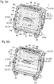
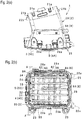
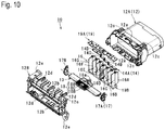
- an airflow-direction adjustment device 10 of the second embodiment comprises a case 12 set in such a way as to blow out air to an outside from an inside; a horizontal-type fin 13 pivotally supported turnably relative to bearing brackets 17A and 17B (17) facing on right and left near a front opening inside the case 12; a plurality (in the embodiment, seven pieces) of vertical-type fins 16A to 16G (16) wherein top and bottom ends are pivotally supported turnably relative to bearing brackets 19A and 19B (19) facing on top and bottom on a deep side of the front opening inside the case 12; a link mechanism 14 associating two or more fins among each fin 16; and an operating knob 18.
- the horizontal-type fin 13 can adjustably switch an airflow direction by turning a back side up and down only at a predetermined angle as a supporting point on a front side of a plate width.
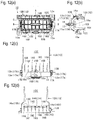
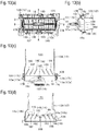
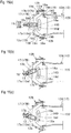
- the vertical-type fins 16A to 16G (16) can adjustably switch between the parallel air-blowing mode (see Figs. 12(a) to 12(d) ) which becomes approximately parallel to each other; and the scattered air-blowing mode (see Figs.
- the knob 18 is turned in the same direction by operating to move horizontally, i.e. to a left or right side, so that each vertical-type fin 16A to 16G is switched to an inclined air-blowing mode which becomes non-parallel to the brackets 17A and 17B which are support portions.
- the knob 18 is supported in the horizontal-type fin 13, and movable to front and back, and right and left in a state connected to the intermediate fin 16D among the vertical-type fins 16.
- the link mechanism 14 includes two first links 14B and 14C turnably connecting respectively the intermediate fin 16D, and the first fins 16C and 16E disposed on both adjacent sides of the intermediate fin 16D; and furthermore, two second links 14A and 14D for associating or synchronizing the second fins 16B and 16F disposed on sides opposite to the intermediate fin 16D among both adjacent sides of the first fins 16C and 16E, the third fins 16A and 16G disposed outside the second fins 16B and 16F as for the plurality of fins 16, the second fins 16B and 16F, and the third fins 16A and 16G with the first fins 16C and 16E.
- structures except for the essential parts can be modified so as to be described briefly.
- a main member 12A and a front frame 12B forming the case 12; the horizontal-type fin 13; each fin 16A to 16G forming the vertical-type fins 16; each link 14A to 14D forming the link mechanism 14; an upper knob 18A and a lower knob 18B forming the knob 18; the right and left brackets 17A and 17B (17) which are the support portions; and the top and bottom brackets 19A and 19B (19) which are second support portions, are all resin articles; however, they may be made of materials other than resin.
- the case 12 is formed to divide an inner space 12C by the main member 12A having an approximately cylinder shape, and the front frame 12B which is the decorative frame mounted on a front side of the main member 12A.
- the main member 12A and the front frame 12B are positioned by engaging a piece portion 12b on a front frame side with a receiving portion 12a on a main member side.
- a connection piece 12d on the front frame side is engaged with a locking portion 12c on the main member side so as to become the case 12 as an integrated article.
- the case 12 is mounted on the installation portion of the vehicle and the like using an attachment portion 12e provided in the front frame 12B.
- the inner space 12C opens in the front-and-back direction, and a front frame 12B side is set as the air outlet, and a back end side is set as the air inlet.
- brackets 17A and 17B for the horizontal-type fin 13 are mounted on an inside face of the right and left of the main member; and the brackets 19A and 19B for the vertical-type fins are mounted on an inner face of the top and bottom of the main member.
- the brackets 17A and 17B there are provided a shaft hole 17a on a front side (a side where the air is blown out to the outside), and an arc groove 17b on a back side (a back side in the inner space) facing each other respectively (see Fig. 11 ).
- the arc groove 17b has a gentle arc shape around the shaft hole 17a.
- the brackets 19A and 19B there are formed seven shaft holes 19a to 19g in a state facing on top and bottom.
- the shaft holes 19a to 19g are provided approximately at an equal interval.
- the shaft holes 19a to 19c and the shaft holes 19e to 19g are simple through-holes.
- the intermediate shaft hole 19d is formed in a groove shape having an approximately concave shape, i.e. a dovetail groove shape which can move shaft portions 16a of the later-described intermediate fin 16D in a bracket plate-width direction.
- the fins 16A to 16G include the shaft portions 16a located on upper and lower end faces and protruding on the same shaft line respectively in an approximately middle in a plate width direction; and shaft portions 16b located on the upper end face, and projected in a step formed such that a back side where the shaft portion 16a does not protrude is formed in one step below.
- the upper and lower shaft portions 16a of the fins 16A to 16C and 16E to 16G are formed in a simple convex shape.
- each upper and lower shaft portion 16a of the intermediate fin 16D has a small-diameter neck movable along the dovetail groove shape of the aforementioned shaft hole 19d.
- each upper and lower shaft portion 16a is supported turnably and movably to front and back in the shaft hole 19d having the dovetail groove shape of the brackets 19A and 19B.
- the fins 16A to 16G are operated to be connected by four links 14A to 14D forming the link mechanism 14.
- the intermediate fin 16D positioned in a middle of right and left, and the first fins 16C and 16E disposed on both adjacent sides of the intermediate fin 16D are turnably connected by the two first links 14B and 14C.
- One first fin 16C, the second fin 16B located outside the first fin 16C, and the third fin 16A located outside the second fin 16B are turnably connected by the second link 14A.
- the other first fin 16E, the second fin 16F located outside the first fin 16E, and the third fin 16G located outside the second fin 16F are turnably connected by the second link 14D.
- the intermediate fin 16D there is provided an arc groove 16d in an up-and-down direction on a front side in the plate width direction, and a portion between the arc groove 16d and a front edge portion becomes a graspable piece portion 16c.
- front edge sides of the first fins 16C and 16E and the piece portion 16c are formed in an arc shape.
- the first links 14B and 14C include shaft holes 14a and 14a provided on both end sides. Then, in one first link 14B, the shaft hole 14a on one end side fits into the shaft portion 16b of the first fin 16C, and the shaft hole 14a on the other end side fits into the shaft portion 16b of the intermediate fin 16D. In the other first link 14C, the shaft hole 14a on one end side fits into the shaft portion 16b of the intermediate fin 16D, and the shaft hole 14a on the other end side fits into the shaft portion 16b of the first fin 16E. Also, the second links 14A and 14D are made longer than the first links 14B and 14C, and include three shaft holes 14a respectively provided on both end sides and a middle.
- the shaft hole 14a on one end side fits into the shaft portion 16b of the third fin 16A; the shaft hole 14a on the other end side fits into the shaft portion 16b of the first fin 16C; and the shaft hole 14a in the middle fits into the shaft portion 16b of the second fin 16B.
- the shaft hole 14a on one end side fits into the shaft portion 16b of the third fin 16G; the shaft hole 14a on the other end side fits into the shaft portion 16b of the first fin 16E; and the shaft hole 14a in the middle fits into the shaft portion 16b of the second fin 16F.
- the aforementioned horizontal-type fin 13 is turnably supported between the brackets 17A and 17B.
- the horizontal-type fin 13 includes shaft portions 13a and shaft portions 13b respectively projected on each right and left side face; a relief opening 13c located in an intermediate portion of the right and left, and provided on a back side; a control portion 13d formed such that a just-in-front side is formed one step thicker including an edge portion of the opening 13c; and a hole portion 13e provided in a middle of the control portion 13d.
- the horizontal-type fin 13 is disposed between the brackets 17A and 17B approximately in parallel to the same brackets in a state wherein the shaft portions 13a on both sides are fitted into the corresponding shaft holes 17a, and the shaft portions 13b on both sides are fitted into the arc-shaped guide hole 17b. Consequently, the horizontal-type fin 13 is supported such that the back side in the plate width direction is turnable in an up-and-down direction only at a predetermined angle according to the arc-shaped guide hole 17b as a supporting point of the shaft portion 13a.
- an elastic member (not shown in the drawings) as needed.
- the elastic member is a member moderately pressed against the later-described operating knob 18 so as to prevent the knob 18 from unexpectedly shifting due to vibrations and the like.
- the knob 18 in the horizontal-type fin 13, there is assembled the knob 18 to be movable to front and back only for a predetermined distance, and movable horizontally to right and left only for a predetermined distance at a foremost position.
- the knob 18 is formed by the upper knob 18A and the lower knob 18B sandwiching the fin 13 from top and bottom; and a decorative knob 18C located between both knobs 18A and 18B, and mounted on a front side.
- the upper and lower knobs 18A and 18B include approximately L-shaped piece portions 18a projected in a middle of right and left at a back edge; a step portion 18b provided in an opposed inner face to release the control portion 13d, and control a movement range of the knob 18; a wall portion 18c positioning the decorative knob 18C, and a latching wall 18d provided on a back side of the wall portion 18c to lock both end sides of the decorative knob 18C, respectively provided on an inner face front side of the lower knob 18B; claw portions 18e provided on both sides of the wall portion 18c to engage locking portions (not shown in the drawings) on an upper knob side; an engagement portion 18f provided on an inner face back side of the lower knob 18B to engage a corresponding portion on the upper knob side; and the like.
- the decorative knob 18C is attached relative to the lower knob 18B by locking both end portions in the latching wall 18d.
- the claw portions 18e on a lower knob side, and the engagement portion 18f respectively engage corresponding portions of the upper knob 18A so as to be integrated.
- each piece portion 18a of the upper and lower knobs is disposed in the arc groove 16d of the intermediate fin 16D.
- the knob 18 restrains the piece portion 16c of the intermediate fin 16D inside each piece portion 18a, and with a restraint aspect thereof, the knob 18 is connected or linked to the intermediate fin 16D.
- the details can be modified or developed provided that they comprise the structures defined in the appended claims.
- the structure wherein the front frame is attached to the main member later there is shown the structure wherein the front frame is attached to the main member later; however, the front frame may be omitted, or the shape of the main member or the shape of the front frame are optional as well.
- the vertical-type fins can be omitted, or in the second embodiment according to the invention, the horizontal-type fin can be made as a non-moving type which does not move.
Landscapes
- Engineering & Computer Science (AREA)
- Mechanical Engineering (AREA)
- Physics & Mathematics (AREA)
- Thermal Sciences (AREA)
- Chemical & Material Sciences (AREA)
- Combustion & Propulsion (AREA)
- General Engineering & Computer Science (AREA)
- Air-Flow Control Members (AREA)
- Air-Conditioning For Vehicles (AREA)
Claims (6)
- Dispositif de réglage de direction de flux d'air (10) comprenant:un boîtier (12) placé de manière à souffler de l'air vers l'extérieur depuis une partie d'ouverture côté avant ;une pluralité d'ailettes (16) dont les extrémités supérieures et inférieures sont supportées de manière pivotante en rotation par rapport aux parties de support opposées à l'intérieur du boîtier (12) ;un mécanisme de liaison (14) associant deux ou plusieurs ailettes ; etun bouton de commande (18) permettant de commuter de façon réglable entre un mode de soufflage d'air parallèle selon lequel les ailettes deviennent sensiblement parallèles les unes aux autres, et un mode de soufflage d'air diffusé selon lequel deux ou plusieurs ailettes (16C, 16E) sont tournées dans une direction opposée entre elles par l'intermédiaire du bouton (18)en ce que le bouton (18) est supporté de façon mobile vers l'avant et l'arrière et vers la droite et la gauche dans un état relié à une ailette intermédiaire (16D) disposée au milieu parmi la pluralité d'ailettes (16), et le mécanisme de liaison (14) comporte deux premières liaisons (14B, 14C), chacune étant reliée en rotation au niveau d'une extrémité à une première ailette (16C, 16E) disposée de manière adjacente à l'ailette intermédiaire (16D), et étant reliée en rotation au niveau de l'autre extrémité à l'ailette intermédiaire (16D), caractérisé en ce que le bouton (18) est connecté ou relié à l'ailette intermédiaire (16D) par le biais d'une partie de pièce (16c) de l'ailette intermédiaire (16D) et dû à un mouvement vers l'avant de l'ailette intermédiaire (16D), la partie de pièce (16c) et le côté avant entrent dans une ouverture de décharge (13c) située dans une partie intermédiaire de la droite et de la gauche d'une ailette de type horizontal (13) supportant le bouton (18) et située en aval des ailettes de type vertical (16) devant être débloquées en maintenant un état approximativement parallèle aux supports (17A, 17B) montés sur une face intérieure de la droite et de la gauche du boîtier (12) et l'ailette de type horizontal (13) étant supportée par les supports (17A, 17B).
- Dispositif de réglage de direction de flux d'air selon la revendication 1, en ce que la pluralité d'ailettes (16) comporte une deuxième ailette (16B) disposée sur un côté opposé à l'ailette intermédiaire (16D) parmi deux côtés adjacents de la première ailette (16C) ; et une troisième ailette (16A) disposée sur un côté opposé à la première ailette (16C) parmi deux côtés adjacents de la deuxième ailette (16B), et le mécanisme de liaison (14) comporte deux seconds liens (14A, 14D) reliant en rotation respectivement la première ailette (16C), la seconde ailette (16B) et la troisième ailette (16A).
- Dispositif de réglage de direction de flux d'air selon la revendication 2, comprenant en outre ladite ailette de type horizontal (13) en ce que les deux côtés d'extrémité droit et gauche sont supportés de manière pivotante en rotation par rapport aux supports (17A, 17B) à l'intérieur du boîtier (12), en ce que le bouton (18) est supporté de manière mobile vers l'avant et l'arrière et vers la droite et la gauche par rapport à l'ailette de type horizontal (13), et actionné pour avancer afin de commuter la première ailette (16C), ou la première ailette (16C) et la deuxième ailette (16B), ou la première ailette (16C) à la troisième ailette (16G) du mode de soufflage d'air parallèle en mode de soufflage d'air diffusé par le biais du mécanisme de liaison (14).
- Dispositif de réglage de direction de flux d'air selon la revendication 2 ou 3, en ce que dans un état avancé, le bouton (18) est actionné pour être poussé vers l'arrière afin de commuter la première ailette (16C), ou la première ailette (16C) et la deuxième ailette (16B), ou la première ailette (16C) à la troisième ailette (16G) du mode de soufflage d'air diffusé en mode de soufflage d'air parallèle qui devient approximativement parallèle aux supports (17A, 17B) par le biais du mécanisme de liaison (14), et dans un état dans lequel le bouton (18) est actionné pour avancer vers un côté gauche ou droit afin de tourner chaque ailette (16) dans une direction approximativement identique de manière à commuter en un mode de soufflage d'air incliné qui devient non parallèle aux supports (17A, 17B).
- Dispositif de réglage de direction de flux d'air selon la revendication 1, en ce que dans l'autre première liaison (14C), le trou d'arbre (14a) sur un côté d'extrémité s'emboîte dans la partie d'arbre (16b) de l'ailette intermédiaire (16D), et le trou d'arbre (14a) sur l'autre côté d'extrémité s'emboîte dans la partie d'arbre (16b) de la première ailette (16E), en ce que les secondes liaisons (14A) et (14D) sont plus longues que les premières liaisons (14B) et (14C), et comportent trois trous d'arbre (14a) respectivement ménagés sur les deux côtés d'extrémité et au milieu, en ce que dans une seconde liaison (14A), le trou d'arbre (14a) sur un côté d'extrémité s'emboîte dans la partie d'arbre (16b) de la troisième ailette (16A) ; le trou d'arbre (14a) sur l'autre côté d'extrémité s'emboîte dans la partie d'arbre (16b) de la première ailette (16C) ; et le trou d'arbre (14a) au milieu s'emboîte dans la partie d'arbre (16b) de la deuxième ailette (16B), en ce que dans l'autre seconde liaison (14D), le trou d'arbre (14a) sur un côté d'extrémité s'emboîte dans la partie d'arbre (16b) de la troisième ailette (16G) ; le trou d'arbre (14a) sur l'autre côté d'extrémité s'emboîte dans la partie d'arbre (16b) de la première ailette (16E) ; et le trou d'arbre (14a) au milieu s'emboîte dans la partie d'arbre (16b) de la deuxième ailette (16F).
- Dispositif de réglage de direction de flux d'air selon la revendication 1, en ce que l'ailette de type horizontal (13) comporte des parties d'arbre (13a) et des parties d'arbre (13b) respectivement en saillie sur chaque face latérale droite et gauche ; l'ouverture de décharge (13c) située dans une partie intermédiaire de droite et de gauche et ménagée sur un côté arrière ; une partie de commande (13d) formée de telle sorte qu'un côté juste à l'avant est formé d'un étage plus épais comportant une partie de bord de l'ouverture (13c) ; et une partie de trou (13e) ménagée au milieu de la partie de commande (13d).
Applications Claiming Priority (2)
| Application Number | Priority Date | Filing Date | Title |
|---|---|---|---|
| JP2013256623 | 2013-12-12 | ||
| PCT/JP2014/082863 WO2015087975A1 (fr) | 2013-12-12 | 2014-12-11 | Dispositif de réglage de direction d'écoulement d'air |
Publications (3)
| Publication Number | Publication Date |
|---|---|
| EP3081412A1 EP3081412A1 (fr) | 2016-10-19 |
| EP3081412A4 EP3081412A4 (fr) | 2017-11-15 |
| EP3081412B1 true EP3081412B1 (fr) | 2020-07-01 |
Family
ID=53371274
Family Applications (1)
| Application Number | Title | Priority Date | Filing Date |
|---|---|---|---|
| EP14870499.2A Active EP3081412B1 (fr) | 2013-12-12 | 2014-12-11 | Dispositif de réglage de direction d'écoulement d'air |
Country Status (6)
| Country | Link |
|---|---|
| US (1) | US10254004B2 (fr) |
| EP (1) | EP3081412B1 (fr) |
| JP (1) | JP6120992B2 (fr) |
| KR (2) | KR20150068900A (fr) |
| CN (1) | CN105813872B (fr) |
| WO (1) | WO2015087975A1 (fr) |
Families Citing this family (25)
| Publication number | Priority date | Publication date | Assignee | Title |
|---|---|---|---|---|
| CN105813868B (zh) * | 2013-12-06 | 2018-01-09 | 株式会社利富高韩国 | 安装用于车辆通气孔的翼状旋钮的结构 |
| JP6260543B2 (ja) * | 2015-01-13 | 2018-01-17 | トヨタ自動車株式会社 | レジスタ |
| JP6534526B2 (ja) * | 2015-01-13 | 2019-06-26 | 豊和化成株式会社 | レジスタ用操作ノブ |
| KR101683508B1 (ko) * | 2015-06-26 | 2016-12-07 | 현대자동차 주식회사 | 차량용 에어 벤트 장치 |
| JP6500235B2 (ja) * | 2015-11-16 | 2019-04-17 | 豊田合成株式会社 | 空調用レジスタ |
| JP6385007B2 (ja) * | 2015-11-30 | 2018-09-05 | 株式会社ニフコ | 風向調整装置 |
| KR101684192B1 (ko) | 2015-12-10 | 2016-12-07 | 현대자동차주식회사 | 자동차용 에어벤트 |
| DE102015017009B4 (de) * | 2015-12-30 | 2018-04-26 | Faurecia Innenraum Systeme Gmbh | Auslassvorrichtung |
| JP6629168B2 (ja) * | 2016-11-10 | 2020-01-15 | 株式会社ニフコ | 風向調整装置 |
| US10752088B2 (en) * | 2016-12-09 | 2020-08-25 | Tesla, Inc. | Infotainment system with air-vent control |
| JP2019038390A (ja) | 2017-08-25 | 2019-03-14 | 豊田合成株式会社 | 空調用レジスタ |
| KR102394803B1 (ko) * | 2017-09-25 | 2022-05-04 | 현대자동차주식회사 | 자동차용 슬림형 에어벤트 장치 |
| US10807443B2 (en) * | 2017-10-31 | 2020-10-20 | Honda Motor Co., Ltd. | Air vent for a vehicle HVAC system |
| CN107856502B (zh) * | 2017-11-09 | 2019-12-31 | 安徽江淮汽车集团股份有限公司 | 空调出风口组件 |
| IT201800002534A1 (it) | 2018-02-09 | 2019-08-09 | Plastic Components And Modules Automotive S P A | Diffusore di aerazione per veicoli. |
| KR102598528B1 (ko) * | 2018-05-16 | 2023-11-03 | 현대자동차주식회사 | 자동차용 전동식 에어벤트 장치 |
| KR102359587B1 (ko) * | 2019-04-04 | 2022-02-07 | 현대자동차주식회사 | 에어벤트 장치 |
| CN110103676A (zh) * | 2019-04-19 | 2019-08-09 | 浙江吉利控股集团有限公司 | 一种车载空调出风调节装置及具有该调节装置的车辆 |
| CN110341439B (zh) * | 2019-07-09 | 2021-03-26 | 比亚迪股份有限公司 | 一种出风口导风结构及其安装方法 |
| CN110588292A (zh) * | 2019-07-27 | 2019-12-20 | 浙江智动汽车部件有限公司 | 一种新型的出风口叶片结构 |
| CN110500756B (zh) * | 2019-09-07 | 2023-08-22 | 珠海格力电器股份有限公司 | 一种出风组件、控制方法及空调 |
| DE102020207151A1 (de) * | 2020-06-08 | 2021-12-09 | Volkswagen Aktiengesellschaft | Luftausströmer für ein Kraftfahrzeug |
| US11940171B2 (en) * | 2021-01-19 | 2024-03-26 | Air Distribution Technologies Ip, Llc | Diffuser adjustment assembly systems and methods |
| CN113212116B (zh) * | 2021-06-03 | 2022-06-14 | 宁波均胜群英汽车系统股份有限公司 | 一种联动控制的出风口 |
| CN114056057B (zh) * | 2021-12-30 | 2024-01-16 | 上海延锋金桥汽车饰件系统有限公司 | 用于交通工具的通风口装置 |
Family Cites Families (14)
| Publication number | Priority date | Publication date | Assignee | Title |
|---|---|---|---|---|
| JPS5920591Y2 (ja) * | 1980-09-17 | 1984-06-15 | トヨタ自動車株式会社 | ク−ラ吹出口構造 |
| JPS5972440U (ja) * | 1982-11-06 | 1984-05-17 | トヨタ自動車株式会社 | 空気吹出しグリル装置 |
| JPS5991531U (ja) * | 1982-12-10 | 1984-06-21 | トヨタ自動車株式会社 | 空気吹出しグリル装置 |
| JPS60178741U (ja) * | 1984-05-07 | 1985-11-27 | 株式会社日立ホームテック | 風向切替装置 |
| JPH0387155U (fr) * | 1989-12-22 | 1991-09-04 | ||
| JPH0461247U (fr) * | 1990-10-01 | 1992-05-26 | ||
| US5364303A (en) * | 1993-07-09 | 1994-11-15 | Summit Polymers, Inc. | Air vent adjustable vanes for controlling air flow direction |
| FR2710879B1 (fr) * | 1993-10-06 | 1996-01-05 | Peugeot | Aérateur perfectionné, notamment pour planche de bord de véhicule automobile. |
| US5690550A (en) | 1996-04-24 | 1997-11-25 | Manchester Plastics, Inc. | Diffuser outlet assembly |
| DE20100740U1 (de) | 2001-01-16 | 2001-05-31 | TRW Automotive Electronics & Components GmbH & Co.KG, 67677 Enkenbach-Alsenborn | Luft-Ausströmer, insbesondere zur Fahrzeugklimatisierung |
| JP4379188B2 (ja) * | 2004-04-22 | 2009-12-09 | 豊田合成株式会社 | 空調用レジスタ |
| JP4890203B2 (ja) * | 2006-11-20 | 2012-03-07 | 豊和化成株式会社 | 車室内用空気吹出装置 |
| JP5404713B2 (ja) * | 2011-08-11 | 2014-02-05 | 三菱電機株式会社 | 左右風向調整装置およびこれを装備した空気調和機の室内機 |
| DE102011115178B4 (de) * | 2011-09-28 | 2014-10-09 | Audi Ag | Luftausströmer eines Lüftungs- und Heizungsmoduls für Kraftfahrzeuge mit einer Umschaltung zwischen einer Spotstellung und einer Diffusstellung |
-
2014
- 2014-11-26 KR KR1020140166098A patent/KR20150068900A/ko not_active Ceased
- 2014-12-11 KR KR1020167017338A patent/KR101928633B1/ko active Active
- 2014-12-11 JP JP2015552514A patent/JP6120992B2/ja active Active
- 2014-12-11 US US15/104,058 patent/US10254004B2/en active Active
- 2014-12-11 CN CN201480067337.2A patent/CN105813872B/zh active Active
- 2014-12-11 EP EP14870499.2A patent/EP3081412B1/fr active Active
- 2014-12-11 WO PCT/JP2014/082863 patent/WO2015087975A1/fr not_active Ceased
Non-Patent Citations (1)
| Title |
|---|
| None * |
Also Published As
| Publication number | Publication date |
|---|---|
| JP6120992B2 (ja) | 2017-04-26 |
| EP3081412A4 (fr) | 2017-11-15 |
| CN105813872B (zh) | 2019-02-05 |
| US10254004B2 (en) | 2019-04-09 |
| KR20160091415A (ko) | 2016-08-02 |
| CN105813872A (zh) | 2016-07-27 |
| WO2015087975A1 (fr) | 2015-06-18 |
| JPWO2015087975A1 (ja) | 2017-03-16 |
| EP3081412A1 (fr) | 2016-10-19 |
| US20160313025A1 (en) | 2016-10-27 |
| KR20150068900A (ko) | 2015-06-22 |
| KR101928633B1 (ko) | 2018-12-12 |
Similar Documents
| Publication | Publication Date | Title |
|---|---|---|
| EP3081412B1 (fr) | Dispositif de réglage de direction d'écoulement d'air | |
| US10807442B2 (en) | Wind direction adjustment device | |
| EP2881272B1 (fr) | Registre | |
| JP2007118660A (ja) | 車両用シートスライド装置およびその組み立て方法 | |
| CN212447322U (zh) | 用于手套箱的机械式按钮解锁机构及手套箱 | |
| JP2016210219A (ja) | 空調用レジスタ | |
| JP6350341B2 (ja) | 空調用レジスタ | |
| JP6499609B2 (ja) | 車両用レジスタ装置 | |
| KR101305807B1 (ko) | 에어벤트윙 조립체 | |
| JP2016052815A (ja) | レジスタ | |
| JP2019006380A (ja) | ヘッドレスト | |
| JP2016223674A (ja) | 部材の係止構造及び風向調整装置 | |
| JP7270561B2 (ja) | レジスタ | |
| JP5488554B2 (ja) | 車両用シートスライド装置 | |
| JP6800465B2 (ja) | 空調用レジスタ | |
| JP7561091B2 (ja) | 空調用レジスタフィン | |
| JP5011089B2 (ja) | 車両用内装部材の取付構造 | |
| JP5855908B2 (ja) | 椅子 | |
| JP6672703B2 (ja) | 規制装置 | |
| JP7119855B2 (ja) | 空調用レジスタ | |
| WO2016163286A1 (fr) | Dispositif de siège de véhicule | |
| JP2015140532A (ja) | ロック装置 | |
| JP7667071B2 (ja) | 風向調整装置及びエアベント | |
| JP5846439B2 (ja) | パッケージトレイ | |
| JP2013094594A (ja) | 椅子 |
Legal Events
| Date | Code | Title | Description |
|---|---|---|---|
| PUAI | Public reference made under article 153(3) epc to a published international application that has entered the european phase |
Free format text: ORIGINAL CODE: 0009012 |
|
| 17P | Request for examination filed |
Effective date: 20160617 |
|
| AK | Designated contracting states |
Kind code of ref document: A1 Designated state(s): AL AT BE BG CH CY CZ DE DK EE ES FI FR GB GR HR HU IE IS IT LI LT LU LV MC MK MT NL NO PL PT RO RS SE SI SK SM TR |
|
| AX | Request for extension of the european patent |
Extension state: BA ME |
|
| DAX | Request for extension of the european patent (deleted) | ||
| A4 | Supplementary search report drawn up and despatched |
Effective date: 20171018 |
|
| RIC1 | Information provided on ipc code assigned before grant |
Ipc: B60H 1/34 20060101AFI20171012BHEP Ipc: F24F 13/075 20060101ALI20171012BHEP Ipc: F24F 13/06 20060101ALI20171012BHEP Ipc: F24F 13/15 20060101ALI20171012BHEP Ipc: F24F 13/14 20060101ALI20171012BHEP |
|
| STAA | Information on the status of an ep patent application or granted ep patent |
Free format text: STATUS: EXAMINATION IS IN PROGRESS |
|
| 17Q | First examination report despatched |
Effective date: 20180928 |
|
| GRAP | Despatch of communication of intention to grant a patent |
Free format text: ORIGINAL CODE: EPIDOSNIGR1 |
|
| STAA | Information on the status of an ep patent application or granted ep patent |
Free format text: STATUS: GRANT OF PATENT IS INTENDED |
|
| GRAS | Grant fee paid |
Free format text: ORIGINAL CODE: EPIDOSNIGR3 |
|
| INTG | Intention to grant announced |
Effective date: 20200309 |
|
| GRAA | (expected) grant |
Free format text: ORIGINAL CODE: 0009210 |
|
| STAA | Information on the status of an ep patent application or granted ep patent |
Free format text: STATUS: THE PATENT HAS BEEN GRANTED |
|
| AK | Designated contracting states |
Kind code of ref document: B1 Designated state(s): AL AT BE BG CH CY CZ DE DK EE ES FI FR GB GR HR HU IE IS IT LI LT LU LV MC MK MT NL NO PL PT RO RS SE SI SK SM TR |
|
| REG | Reference to a national code |
Ref country code: AT Ref legal event code: REF Ref document number: 1285843 Country of ref document: AT Kind code of ref document: T Effective date: 20200715 Ref country code: CH Ref legal event code: EP |
|
| REG | Reference to a national code |
Ref country code: IE Ref legal event code: FG4D |
|
| REG | Reference to a national code |
Ref country code: DE Ref legal event code: R096 Ref document number: 602014067351 Country of ref document: DE |
|
| REG | Reference to a national code |
Ref country code: LT Ref legal event code: MG4D |
|
| PG25 | Lapsed in a contracting state [announced via postgrant information from national office to epo] |
Ref country code: BG Free format text: LAPSE BECAUSE OF FAILURE TO SUBMIT A TRANSLATION OF THE DESCRIPTION OR TO PAY THE FEE WITHIN THE PRESCRIBED TIME-LIMIT Effective date: 20201001 |
|
| REG | Reference to a national code |
Ref country code: NL Ref legal event code: MP Effective date: 20200701 |
|
| REG | Reference to a national code |
Ref country code: AT Ref legal event code: MK05 Ref document number: 1285843 Country of ref document: AT Kind code of ref document: T Effective date: 20200701 |
|
| PG25 | Lapsed in a contracting state [announced via postgrant information from national office to epo] |
Ref country code: AT Free format text: LAPSE BECAUSE OF FAILURE TO SUBMIT A TRANSLATION OF THE DESCRIPTION OR TO PAY THE FEE WITHIN THE PRESCRIBED TIME-LIMIT Effective date: 20200701 Ref country code: NO Free format text: LAPSE BECAUSE OF FAILURE TO SUBMIT A TRANSLATION OF THE DESCRIPTION OR TO PAY THE FEE WITHIN THE PRESCRIBED TIME-LIMIT Effective date: 20201001 Ref country code: GR Free format text: LAPSE BECAUSE OF FAILURE TO SUBMIT A TRANSLATION OF THE DESCRIPTION OR TO PAY THE FEE WITHIN THE PRESCRIBED TIME-LIMIT Effective date: 20201002 Ref country code: CZ Free format text: LAPSE BECAUSE OF FAILURE TO SUBMIT A TRANSLATION OF THE DESCRIPTION OR TO PAY THE FEE WITHIN THE PRESCRIBED TIME-LIMIT Effective date: 20200701 Ref country code: SE Free format text: LAPSE BECAUSE OF FAILURE TO SUBMIT A TRANSLATION OF THE DESCRIPTION OR TO PAY THE FEE WITHIN THE PRESCRIBED TIME-LIMIT Effective date: 20200701 Ref country code: ES Free format text: LAPSE BECAUSE OF FAILURE TO SUBMIT A TRANSLATION OF THE DESCRIPTION OR TO PAY THE FEE WITHIN THE PRESCRIBED TIME-LIMIT Effective date: 20200701 Ref country code: FI Free format text: LAPSE BECAUSE OF FAILURE TO SUBMIT A TRANSLATION OF THE DESCRIPTION OR TO PAY THE FEE WITHIN THE PRESCRIBED TIME-LIMIT Effective date: 20200701 Ref country code: LT Free format text: LAPSE BECAUSE OF FAILURE TO SUBMIT A TRANSLATION OF THE DESCRIPTION OR TO PAY THE FEE WITHIN THE PRESCRIBED TIME-LIMIT Effective date: 20200701 Ref country code: PT Free format text: LAPSE BECAUSE OF FAILURE TO SUBMIT A TRANSLATION OF THE DESCRIPTION OR TO PAY THE FEE WITHIN THE PRESCRIBED TIME-LIMIT Effective date: 20201102 Ref country code: HR Free format text: LAPSE BECAUSE OF FAILURE TO SUBMIT A TRANSLATION OF THE DESCRIPTION OR TO PAY THE FEE WITHIN THE PRESCRIBED TIME-LIMIT Effective date: 20200701 |
|
| PG25 | Lapsed in a contracting state [announced via postgrant information from national office to epo] |
Ref country code: IS Free format text: LAPSE BECAUSE OF FAILURE TO SUBMIT A TRANSLATION OF THE DESCRIPTION OR TO PAY THE FEE WITHIN THE PRESCRIBED TIME-LIMIT Effective date: 20201101 Ref country code: LV Free format text: LAPSE BECAUSE OF FAILURE TO SUBMIT A TRANSLATION OF THE DESCRIPTION OR TO PAY THE FEE WITHIN THE PRESCRIBED TIME-LIMIT Effective date: 20200701 Ref country code: RS Free format text: LAPSE BECAUSE OF FAILURE TO SUBMIT A TRANSLATION OF THE DESCRIPTION OR TO PAY THE FEE WITHIN THE PRESCRIBED TIME-LIMIT Effective date: 20200701 Ref country code: PL Free format text: LAPSE BECAUSE OF FAILURE TO SUBMIT A TRANSLATION OF THE DESCRIPTION OR TO PAY THE FEE WITHIN THE PRESCRIBED TIME-LIMIT Effective date: 20200701 |
|
| PG25 | Lapsed in a contracting state [announced via postgrant information from national office to epo] |
Ref country code: NL Free format text: LAPSE BECAUSE OF FAILURE TO SUBMIT A TRANSLATION OF THE DESCRIPTION OR TO PAY THE FEE WITHIN THE PRESCRIBED TIME-LIMIT Effective date: 20200701 |
|
| REG | Reference to a national code |
Ref country code: DE Ref legal event code: R097 Ref document number: 602014067351 Country of ref document: DE |
|
| PG25 | Lapsed in a contracting state [announced via postgrant information from national office to epo] |
Ref country code: RO Free format text: LAPSE BECAUSE OF FAILURE TO SUBMIT A TRANSLATION OF THE DESCRIPTION OR TO PAY THE FEE WITHIN THE PRESCRIBED TIME-LIMIT Effective date: 20200701 Ref country code: SM Free format text: LAPSE BECAUSE OF FAILURE TO SUBMIT A TRANSLATION OF THE DESCRIPTION OR TO PAY THE FEE WITHIN THE PRESCRIBED TIME-LIMIT Effective date: 20200701 Ref country code: EE Free format text: LAPSE BECAUSE OF FAILURE TO SUBMIT A TRANSLATION OF THE DESCRIPTION OR TO PAY THE FEE WITHIN THE PRESCRIBED TIME-LIMIT Effective date: 20200701 Ref country code: IT Free format text: LAPSE BECAUSE OF FAILURE TO SUBMIT A TRANSLATION OF THE DESCRIPTION OR TO PAY THE FEE WITHIN THE PRESCRIBED TIME-LIMIT Effective date: 20200701 Ref country code: DK Free format text: LAPSE BECAUSE OF FAILURE TO SUBMIT A TRANSLATION OF THE DESCRIPTION OR TO PAY THE FEE WITHIN THE PRESCRIBED TIME-LIMIT Effective date: 20200701 |
|
| PLBE | No opposition filed within time limit |
Free format text: ORIGINAL CODE: 0009261 |
|
| STAA | Information on the status of an ep patent application or granted ep patent |
Free format text: STATUS: NO OPPOSITION FILED WITHIN TIME LIMIT |
|
| PG25 | Lapsed in a contracting state [announced via postgrant information from national office to epo] |
Ref country code: AL Free format text: LAPSE BECAUSE OF FAILURE TO SUBMIT A TRANSLATION OF THE DESCRIPTION OR TO PAY THE FEE WITHIN THE PRESCRIBED TIME-LIMIT Effective date: 20200701 |
|
| 26N | No opposition filed |
Effective date: 20210406 |
|
| PG25 | Lapsed in a contracting state [announced via postgrant information from national office to epo] |
Ref country code: SK Free format text: LAPSE BECAUSE OF FAILURE TO SUBMIT A TRANSLATION OF THE DESCRIPTION OR TO PAY THE FEE WITHIN THE PRESCRIBED TIME-LIMIT Effective date: 20200701 |
|
| REG | Reference to a national code |
Ref country code: CH Ref legal event code: PL |
|
| GBPC | Gb: european patent ceased through non-payment of renewal fee |
Effective date: 20201211 |
|
| PG25 | Lapsed in a contracting state [announced via postgrant information from national office to epo] |
Ref country code: SI Free format text: LAPSE BECAUSE OF FAILURE TO SUBMIT A TRANSLATION OF THE DESCRIPTION OR TO PAY THE FEE WITHIN THE PRESCRIBED TIME-LIMIT Effective date: 20200701 Ref country code: MC Free format text: LAPSE BECAUSE OF FAILURE TO SUBMIT A TRANSLATION OF THE DESCRIPTION OR TO PAY THE FEE WITHIN THE PRESCRIBED TIME-LIMIT Effective date: 20200701 |
|
| REG | Reference to a national code |
Ref country code: BE Ref legal event code: MM Effective date: 20201231 |
|
| PG25 | Lapsed in a contracting state [announced via postgrant information from national office to epo] |
Ref country code: FR Free format text: LAPSE BECAUSE OF NON-PAYMENT OF DUE FEES Effective date: 20201231 Ref country code: LU Free format text: LAPSE BECAUSE OF NON-PAYMENT OF DUE FEES Effective date: 20201211 Ref country code: IE Free format text: LAPSE BECAUSE OF NON-PAYMENT OF DUE FEES Effective date: 20201211 |
|
| PG25 | Lapsed in a contracting state [announced via postgrant information from national office to epo] |
Ref country code: CH Free format text: LAPSE BECAUSE OF NON-PAYMENT OF DUE FEES Effective date: 20201231 Ref country code: GB Free format text: LAPSE BECAUSE OF NON-PAYMENT OF DUE FEES Effective date: 20201211 Ref country code: LI Free format text: LAPSE BECAUSE OF NON-PAYMENT OF DUE FEES Effective date: 20201231 |
|
| PG25 | Lapsed in a contracting state [announced via postgrant information from national office to epo] |
Ref country code: IS Free format text: LAPSE BECAUSE OF FAILURE TO SUBMIT A TRANSLATION OF THE DESCRIPTION OR TO PAY THE FEE WITHIN THE PRESCRIBED TIME-LIMIT Effective date: 20201101 Ref country code: TR Free format text: LAPSE BECAUSE OF FAILURE TO SUBMIT A TRANSLATION OF THE DESCRIPTION OR TO PAY THE FEE WITHIN THE PRESCRIBED TIME-LIMIT Effective date: 20200701 Ref country code: MT Free format text: LAPSE BECAUSE OF FAILURE TO SUBMIT A TRANSLATION OF THE DESCRIPTION OR TO PAY THE FEE WITHIN THE PRESCRIBED TIME-LIMIT Effective date: 20200701 Ref country code: CY Free format text: LAPSE BECAUSE OF FAILURE TO SUBMIT A TRANSLATION OF THE DESCRIPTION OR TO PAY THE FEE WITHIN THE PRESCRIBED TIME-LIMIT Effective date: 20200701 |
|
| PG25 | Lapsed in a contracting state [announced via postgrant information from national office to epo] |
Ref country code: MK Free format text: LAPSE BECAUSE OF FAILURE TO SUBMIT A TRANSLATION OF THE DESCRIPTION OR TO PAY THE FEE WITHIN THE PRESCRIBED TIME-LIMIT Effective date: 20200701 |
|
| PG25 | Lapsed in a contracting state [announced via postgrant information from national office to epo] |
Ref country code: BE Free format text: LAPSE BECAUSE OF NON-PAYMENT OF DUE FEES Effective date: 20201231 |
|
| PGFP | Annual fee paid to national office [announced via postgrant information from national office to epo] |
Ref country code: DE Payment date: 20251028 Year of fee payment: 12 |