EP3081466B1 - Gesamtheit von elementen, die einen zusammenbau von zwei arten von fahrbaren geräten für kinder ermöglicht - Google Patents
Gesamtheit von elementen, die einen zusammenbau von zwei arten von fahrbaren geräten für kinder ermöglicht Download PDFInfo
- Publication number
- EP3081466B1 EP3081466B1 EP15195187.8A EP15195187A EP3081466B1 EP 3081466 B1 EP3081466 B1 EP 3081466B1 EP 15195187 A EP15195187 A EP 15195187A EP 3081466 B1 EP3081466 B1 EP 3081466B1
- Authority
- EP
- European Patent Office
- Prior art keywords
- platform
- seat
- boss
- mounting
- elements
- Prior art date
- Legal status (The legal status is an assumption and is not a legal conclusion. Google has not performed a legal analysis and makes no representation as to the accuracy of the status listed.)
- Active
Links
Images




Classifications
-
- B—PERFORMING OPERATIONS; TRANSPORTING
- B62—LAND VEHICLES FOR TRAVELLING OTHERWISE THAN ON RAILS
- B62K—CYCLES; CYCLE FRAMES; CYCLE STEERING DEVICES; RIDER-OPERATED TERMINAL CONTROLS SPECIALLY ADAPTED FOR CYCLES; CYCLE AXLE SUSPENSIONS; CYCLE SIDECARS, FORECARS, OR THE LIKE
- B62K15/00—Collapsible or foldable cycles
- B62K15/006—Collapsible or foldable cycles the frame being foldable
-
- B—PERFORMING OPERATIONS; TRANSPORTING
- B62—LAND VEHICLES FOR TRAVELLING OTHERWISE THAN ON RAILS
- B62H—CYCLE STANDS; SUPPORTS OR HOLDERS FOR PARKING OR STORING CYCLES; APPLIANCES PREVENTING OR INDICATING UNAUTHORIZED USE OR THEFT OF CYCLES; LOCKS INTEGRAL WITH CYCLES; DEVICES FOR LEARNING TO RIDE CYCLES
- B62H7/00—Devices for learning to ride cycles, not otherwise provided for, e.g. assisting balance
-
- B—PERFORMING OPERATIONS; TRANSPORTING
- B62—LAND VEHICLES FOR TRAVELLING OTHERWISE THAN ON RAILS
- B62J—CYCLE SADDLES OR SEATS; AUXILIARY DEVICES OR ACCESSORIES SPECIALLY ADAPTED TO CYCLES AND NOT OTHERWISE PROVIDED FOR, e.g. ARTICLE CARRIERS OR CYCLE PROTECTORS
- B62J1/00—Saddles or other seats for cycles; Arrangement thereof; Component parts
-
- B—PERFORMING OPERATIONS; TRANSPORTING
- B62—LAND VEHICLES FOR TRAVELLING OTHERWISE THAN ON RAILS
- B62K—CYCLES; CYCLE FRAMES; CYCLE STEERING DEVICES; RIDER-OPERATED TERMINAL CONTROLS SPECIALLY ADAPTED FOR CYCLES; CYCLE AXLE SUSPENSIONS; CYCLE SIDECARS, FORECARS, OR THE LIKE
- B62K13/00—Cycles convertible to, or transformable into, other types of cycles or land vehicle
-
- B—PERFORMING OPERATIONS; TRANSPORTING
- B62—LAND VEHICLES FOR TRAVELLING OTHERWISE THAN ON RAILS
- B62K—CYCLES; CYCLE FRAMES; CYCLE STEERING DEVICES; RIDER-OPERATED TERMINAL CONTROLS SPECIALLY ADAPTED FOR CYCLES; CYCLE AXLE SUSPENSIONS; CYCLE SIDECARS, FORECARS, OR THE LIKE
- B62K19/00—Cycle frames
- B62K19/30—Frame parts shaped to receive other cycle parts or accessories
-
- B—PERFORMING OPERATIONS; TRANSPORTING
- B62—LAND VEHICLES FOR TRAVELLING OTHERWISE THAN ON RAILS
- B62K—CYCLES; CYCLE FRAMES; CYCLE STEERING DEVICES; RIDER-OPERATED TERMINAL CONTROLS SPECIALLY ADAPTED FOR CYCLES; CYCLE AXLE SUSPENSIONS; CYCLE SIDECARS, FORECARS, OR THE LIKE
- B62K21/00—Steering devices
- B62K21/12—Handlebars; Handlebar stems
-
- B—PERFORMING OPERATIONS; TRANSPORTING
- B62—LAND VEHICLES FOR TRAVELLING OTHERWISE THAN ON RAILS
- B62K—CYCLES; CYCLE FRAMES; CYCLE STEERING DEVICES; RIDER-OPERATED TERMINAL CONTROLS SPECIALLY ADAPTED FOR CYCLES; CYCLE AXLE SUSPENSIONS; CYCLE SIDECARS, FORECARS, OR THE LIKE
- B62K3/00—Bicycles
- B62K3/002—Bicycles without a seat, i.e. the rider operating the vehicle in a standing position, e.g. non-motorized scooters; non-motorized scooters with skis or runners
-
- B—PERFORMING OPERATIONS; TRANSPORTING
- B62—LAND VEHICLES FOR TRAVELLING OTHERWISE THAN ON RAILS
- B62K—CYCLES; CYCLE FRAMES; CYCLE STEERING DEVICES; RIDER-OPERATED TERMINAL CONTROLS SPECIALLY ADAPTED FOR CYCLES; CYCLE AXLE SUSPENSIONS; CYCLE SIDECARS, FORECARS, OR THE LIKE
- B62K5/00—Cycles with handlebars, equipped with three or more main road wheels
- B62K5/02—Tricycles
- B62K5/06—Frames for tricycles
-
- B—PERFORMING OPERATIONS; TRANSPORTING
- B62—LAND VEHICLES FOR TRAVELLING OTHERWISE THAN ON RAILS
- B62K—CYCLES; CYCLE FRAMES; CYCLE STEERING DEVICES; RIDER-OPERATED TERMINAL CONTROLS SPECIALLY ADAPTED FOR CYCLES; CYCLE AXLE SUSPENSIONS; CYCLE SIDECARS, FORECARS, OR THE LIKE
- B62K9/00—Children's cycles
-
- B—PERFORMING OPERATIONS; TRANSPORTING
- B62—LAND VEHICLES FOR TRAVELLING OTHERWISE THAN ON RAILS
- B62K—CYCLES; CYCLE FRAMES; CYCLE STEERING DEVICES; RIDER-OPERATED TERMINAL CONTROLS SPECIALLY ADAPTED FOR CYCLES; CYCLE AXLE SUSPENSIONS; CYCLE SIDECARS, FORECARS, OR THE LIKE
- B62K9/00—Children's cycles
- B62K9/02—Tricycles
Definitions
- Scooter shall be broadly understood as designating any type of craft comprising a platform provided with at least one front wheel, at least one rear wheel and a handle on the front allowing a child to stay on the platform.
- a scooter is an attractive device for a child but must be learned to avoid falls. For this purpose, it is known to provide the mounting of a removable seat on a scooter, which facilitates this learning.
- the present invention aims to remedy these significant disadvantages.
- Patent Application Publications No. US 2014/217685 A1 , CN 202754075 U and DE 20 2011 001596 U1 describe sets of elements for constituting various kinds of wheeled vehicles for children, which do not however make it possible to overcome perfectly the aforementioned drawbacks.
- the set of elements concerned comprises, in a manner known per se, a platform, at least one front wheel, at least one rear wheel, a handle comprising an amount intended to be connected to the front of the platform. , and a removable seat. Said handle is removable relative to the platform, and the platform comprises, on the side of the front wheel or wheels, a receiving well of the lower portion of the amount that comprises this handle, for mounting the handle on the platform.
- the platform includes a front boss.
- the set of elements according to the invention thus makes it possible to constitute either a conventional scooter when said handle is mounted on the front of the platform, or a machine capable of being overlapped when the support body and the seat are mounted. on the platform.
- the adjusted application of this support body on said boss allows a stable mounting of this body on the platform.
- the support body comprises, at a rear end, a well of shape identical to that of the well that includes the platform, adapted to receive the lower portion of the amount that comprises the handle.
- the element assembly thus makes it possible to constitute, in addition, a learning machine, including the platform, the support body, the seat mounted on this body and the handle connected to the rear of this body.
- This handle allows an adult to control the use of the machine by a child.
- the machine can thus, according to the position given to the seat, be adapted to the size of the child, the seat being lower when in the forward position and higher when in the rear position.
- the inclination of said seat mounting portion may in particular be such that a longitudinal axis of this support portion forms, when the support body is mounted on the platform, an angle of the order of 20 to 30 ° with the plane in which the platform generally extends, that is to say a plane parallel to that containing the axes of the wheels.
- the well may have an axis perpendicular to the plane in which the platform generally extends, in which case the handle has a rectilinear amount.
- the well is generally cylindrical in shape and has an axis inclined in a vertical front-rear plane of the platform, towards the rear of this platform; the handle comprises an amount bent at its lower part; this elbow defines a lower portion of the upright, of generally cylindrical shape, which is intended to be engaged in the well with pivoting capacity in this well.
- fore-and-aft vertical plane is meant the longitudinal plane of the platform which is substantially perpendicular to the plane in which the platform generally extends, that is to say a plane parallel to that containing the axes of the wheels.
- the handle is adapted, by pivoting in the well, to move from an unfolding position, in which it is substantially perpendicular to the platform, to a folding position, in which it extends along the platform.
- the set of elements further comprises an elongate element able to be mounted on the platform, transversely to this platform, and having a length such that it protrudes on either side of this platform. in this mounting position.
- said rear extension has a flattened free end portion adapted to bear against the platform, said elongated element being intended to be mounted on the platform between this platform. flattened free end portion and platform.
- the platform may comprise a tapped hole for mounting said elongated element, this elongated element may comprise a central mounting hole, and said flattened free end portion may also comprise a hole, these different holes coming into coincidence with each other in said mounting position and being adapted to receive a mounting screw of the extension and the elongated member on the platform.
- the support body 4 has a front portion 4a and a rear portion 4b for mounting the seat 6.
- the front portion 4a has a front extension 22 and a rear extension 23 defining between them a housing 24 having a shape corresponding in hollow to that of the boss 14.
- This housing thus has a shape adjusted to that of the boss 14 so that the support body 4 is adapted to be engaged on the boss 14 in an adjusted manner, with application of said front extension 22 against the front portion of the boss 14 and application of said rear extension 23 against the rear portion of this boss 14.
- the front extension 22 has an enlarged shape completely covering the front face of the boss 14. At its front end, it comprises a locking cavity 25 with double ducts, coinciding with the homologous cavity formed by the boss 14 during assembly of the body 4 on the subassembly 2. This cavity 25 is able to receive with friction, just like the other cavity, the two rods forming the body of the locking key 5.
- the rear extension 23 is formed of two parallel branches constituting together a base bearing against the rear face of the boss 14 and coming to rest against the platform 10.
- the rear portion 4b has a substantially straight shape and extends from the front portion 4a being inclined with respect to this front portion. As shown in figure 2 , this inclination is such that, when the support body 4 is mounted on the platform 10, the portion 4b has a height increasing towards the rear of the machine 1.
- the angle that makes, in this mounting position, the longitudinal axis of this part 4b with the plane in which the platform extends longitudinally 10 is of the order of 20 to 30 degrees. In other words, this axis longitudinally forms an angle of the order of 110 to 120 degrees with a straight line extending midway between the front extension 22 and the rear extension 23.
- the rear portion 4b comprises three holes 28 for mounting the seat 6, and a rear well 29 for mounting the handle 3.
- the holes 28 are evenly spaced. As is visible on the figure 5 they are arranged at the bottom of cavities that form the support body 4 and are intended to receive screws 31 cooperating with threaded holes formed at the base of the seat 6. They thus allow the mounting of this seat on the body 4 according to a front seat position 6, of lower height, shown on the figure 6 , and a rear position, of higher height, shown on the figure 7 .
- the well 29 has a shape identical to that of the well 13 and thus allows the mounting of the handle 3 on the rear portion of the body 4, so that the handle protrudes from the machine 1, towards the rear and towards the up, as visible on the Figures 3 and 4 .
- the locking key 5 has a gripping head and a body intended to be engaged with friction in the two aforementioned locking cavities. The key 5 thus makes it possible to lock the body 4 in the engagement position on the boss 14.
- the seat 6 comprises meanwhile, a portion forming a seat for a child and a pair of side handles 35 forming a fixed mini-handlebar, which allows the child can stay on this seat.
- the set of elements according to the invention thus makes it possible to constitute either a conventional scooter when the handle 3 is mounted on the platform 10, or a "mini-moto" type machine when the body 4 and the seat 6 are mounted on this platform 10, a learning device when the handle 3 is mounted on the body 4, the handle 3 then allowing an adult, having this handle in hand, to maintain control of the machine 1 and consisting.
- the set of elements according to the second embodiment comprises elements identical or very similar to those of the first embodiment; for simplicity, the elements already described, which are found in this second embodiment, will be designated by the same reference numerals and will not be described again. It will be the same for the third embodiment.
- the set of elements further comprises an elongated element 40 adapted to be mounted on the platform 10, transversely to this platform, and having a length such that it exceeds the share and else of this platform in this mounting position.
- the two parts of this element 40 which protrude on both sides of the platform 10 are able to form footrests for the child riding the seat.
- the rear extension 23 is in this case formed by a single branch ending in a flattened free end portion 23a adapted to bear against the platform.
- the elongated element 40 is intended to be mounted on the platform 10 between this portion 23a and the platform 10.
- the platform 10 comprises a tapped hole; the elongated member 40 includes a central mounting hole, and said portion 23a also includes a central mounting hole.
- These different holes come into coincidence with each other in said mounting position and are adapted to receive a screw 41 for mounting the extension 23 and the element 40 on the platform 10.
- the front extension 22 for its part, comprises a wedging pad 22a capable of coming into fitted engagement in a corresponding cavity formed by the boss 14.
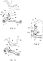
- the well 13 has a generally cylindrical shape and an axis inclined in a vertical front-back plane of the platform 10, this inclination being towards the rear of this platform; the handle 3 then comprises, as visible on the Figures 14 to 17 , an amount 20 which is bent at its lower part. This bend defines a lower portion 20a of the upright 20, of generally cylindrical shape, which is intended to be engaged in the well 13 with pivoting capacity in this well.
- the handle 3 is adapted, by pivoting in the well 13, to move from an unfolding position, in which it is substantially perpendicular to the platform 10, to a folding position, visible on the figure 16 in which it extends along the platform 10.
- the inclination of the axis of the well 13 is of the order of 45 °, and the bent portion of the upright 20 extends over an arc such that the axis of the lower portion 20a forms an angle of the order of 135 ° with the longitudinal axis of the rest of the upright 20.
- the platform 10 is constituted by a structural body 50, the thickness of which makes it possible to form the boss 14, and by a shell 51, of reduced thickness, permitting a covering of the body 50.
- a groove 55 is formed in the body 50 coaxially with the well 13, at the upper part of the latter and just below the hull 51.
- This groove 55 has a diameter greater than that of the opening 54, so that is delimited by the hull 51 in the upper part.
- the groove 55 communicates, at its lower part, with two radial housings 56 diametrically opposite one another. This groove 55 and these housings 56 are able to receive two diametrically opposed projections 75 that includes the portion 20a, as described below.
- the shell 51 forms two radial notches 60 opening into the opening 54 (only one of which is visible on the figures 11 and 15 ).
- the projections 75 are able to be engaged in these notches 60 and then in the groove 55, then in the housing 56.
- the lower portion 20a and the adjacent bent portion house a locking member 70 for controlling the assembly / disassembly and locking of the handle 3 on the platform 10.
- This member 70 comprises a lower locking pin 71 , an intermediate branch and an actuating portion 72.
- the finger 71 forms a right angle with the intermediate branch and is intended to be engaged in one or other of the housing 57, 58.
- the intermediate branch is urged by a spring 73 extending between it and the lower portion 20a, which normally holds the member 70 in the position shown on the figure 14 , in which the finger 71 protrudes radially beyond the wall of the lower portion 20a and is adapted to be engaged in one or the other of the housing 57 or 58.
- the spring 73 is, however, able to be compressed by such that the finger 71 can be brought into a retracted position in which it does not protrude beyond the wall of the lower portion 20a and is thus clear of the housing 57 or 58.
- the actuating portion 72 is bent with respect to the intermediate branch. In the position shown on the figure 14 it projects through a light provided in the lower portion 20a and in said bent portion.
- the locking member 70 is pivotally mounted with respect to this lower portion 20a by means of an axis situated substantially between the intermediate branch and the actuating part 72.
- the lower portion 20a comprises the two aforementioned projections 75, integral with it, which are diametrically opposed to one another and which are arranged on a diameter parallel to the axis in which the finger 71 is movable relative to the lower portion 20a.
- the handle 3 is then pivoted either towards the unfolded position or towards the folding position, and when either of these positions is reached, the protrusions 75 fall into the and into the housings 56 and the finger 71, under the action of the spring 73, enters the housing 57 or the housing 58 as appropriate, thus locking the handle 3 in one or other of these positions.
- the user exerts pressure on the actuating portion 72 so as to bring the locking member 70 in the retracted position mentioned above.
- it exerts an axial traction on the lower portion 20a so as to extract the projections 75 of the housing 56 and to bring these projections 75 in the groove 55.
- the finger 71 is brought above the housing 57, so that maintaining said pressure on the actuating portion 72 becomes unnecessary, and the projections 75 abut against the hull 51, causing undesired extraction of the lower portion 20a out of the well 13 can not occur.
- the handle 3 is then pivoted to the folding position shown on the figure 16 in which the protrusions 75 fall into the respective recesses 56; the lower portion 20a is thus brought into the position in which the finger 71 is placed opposite the housing 58 and engages in this housing under the bias of the spring 73, which locks the handle 3 in this folding position.
- the body 50 forms a threaded hole 80 on the front side of the boss 14 and a cavity 81 on the rear side of this boss.
- a hole is arranged on the front extension 22 and a holding stud 82 is arranged on the rear extension 23; this hole is intended to coincide with the threaded hole 80 in the mounting position of the body 4 on the platform 10, and the stud 82 is intended to engage in said cavity 81 in the same mounting position.
- a screw 85 is intended to be screwed into the threaded hole 80, to ensure the mounting of the body 4 on the platform 10.
- the invention thus provides a set of modular elements 1 having wide possibilities of use, and having decisive advantages.
Landscapes
- Engineering & Computer Science (AREA)
- Mechanical Engineering (AREA)
- Steering Devices For Bicycles And Motorcycles (AREA)
Claims (10)
- Satz von Elementen, die die Möglichkeit bieten, zwei Arten von Rädervorrichtung (1) für Kinder, d. h. eine Vorrichtung des Roller-Typs und eine Vorrichtung, die dazu bestimmt ist, überlappt zu werden, zu bilden, wobei der Satz von Elementen eine Plattform (10), mindestens eine Vorderrad (11), mindestens ein Hinterrad (12), einen Griff (3) mit einem mit der Vorderseite der Plattform (10) Pfosten (20) verbunden wird und einem abnehmbaren Sitz (6) umfasst;- der Griff (3) gegenüber der Plattform (10) abnehmbar ist und die Plattform (10) auf der Seite des Vorderrades oder der Vorderrad (11) eine erste Vertiefung (13) zur Aufnahme des unteren Teils des Pfostens (20) aufweist zum Befestigen des Griffs (3) an der Plattform (10);- die Plattform (10) einen vorderen Vorsprung (14) aufweist;dadurch gekennzeichnet, dass:- die erste Vertiefung (13) öffnet sich am oberen Teil dieses Vorsprungs (14);- der Satz von Elementen einen Sitzstützkörper (4) zum Stützen des Sitzes (6) aufweist, wobei der vordere Abschnitt (4a) eine vordere Verlängerung (22) und eine hintere Verlängerung (23) aufweist, die ein Gehäuse (24) zwischen sich definiert, wobei dieses Gehäuse (24) eine der Form des Vorsprungs (14) entsprechende Hohlform aufweist, so dass nach dem Entfernen des Handgriffs (3) gegenüber der erster Vertiefung (13) der Sitzstützkörper (4) auf den Vorsprung (14) mit dem Aufbringen der vorderen Verlängerung (22) gegen den vorderen Abschnitt des Vorsprungs (14) und das Aufbringen der hinteren Verlängerung (23) gegen den hinteren Teil des Vorsprungs (14) passgenau angeordnet wird;- der Satz von Elementen Befestigungsmittel (28, 31) zum befestigen des Sitzes (6) an dem Sitzstützkörper (4) aufweist und- der Satz von Elementen Befestigungsmittel (5; 41; 80 bis 85) zum befestigen mindestens eines der Verlängerungen (22, 23) an der Plattform (10) aufweist.
- Satz von Elementen nach Anspruch 1, dadurch gekennzeichnet, dass der Sitzstützkörper (4) an einem hinteren Ende eine zweite Vertiefung (29) aufweist, die eine Form ähnlich der Form der ersten Vertiefung (13) aufweist, die die Plattform (10) aufweist, um den unteren Teil des Pfostens (20) aufzunehmen wird, den der Griff (3) aufweist.
- Satz von Elementen nach Anspruch 1 oder 2, dadurch gekennzeichnet, dass:- der Sitzstützkörper (4) einen Sitzbefestigungsabschnitt (4b) des Sitzes (6) aufweist, der sich von dem vorderen Abschnitt (4a) dieses Sitzstützkörpers (4) erstreckt und der in Bezug auf diesen vorderen Abschnitt (4a) geneigt ist, wobei diese Neigung ist dass den Sitzbefestigungsabschnitt (4b) des Sitzes (6) eine zunehmende Höhe in Richtung zu hinter des Fahrzeugs (1) aufweist, wenn der Sitzstützkörper (4) auf der Plattform (10) montiert ist- die Befestigungsmittel (28, 31) zum Befestigen des Sitzes (6) an dem Sitzbefestigungsabschnitt (4b) ermöglichen die Montage des Sitzes (6) in mindestens zwei Positionen auf dem Sitzbefestigungsabschnitt (4b), nämlich einer Vorderseite Position, von geringerer Höhe und mindestens einer Hinterseite Position, von größerer Höhe.
- Satz von Elementen nach Anspruch 3, dadurch gekennzeichnet, dass die Neigung des Sitzbefestigungsabschnitts (4b) des Sitzes (6) derart ist, dass sich eine Längsachse dieses Sitzbefestigungsabschnitts (4b), wenn der Sitzstützkörper (4) an die Plattform (10) angebracht ist, ein Winkel in der Größenordnung von 20 bis 30 ° bildet, mit der Ebene, in der im allgemeinen die Plattform (10) liegt, d.h. eine Ebene parallel zu der, die die Achsen der Räder (11, 12) enthält.
- Satz von Elementen nach einem der Ansprüche 1 bis 4, dadurch gekennzeichnet, dass die Befestigungsmittel mindestens einer der Verlängerungen an der Plattform (10) umfassen:- einen Verriegelungshohlraum, der in dem vorderen Abschnitt des Vorsprungs (14) angeordnet ist;- einen in der vorderen Verlängerung (22) des Sitzstützkörpers (4) ausgebildeten Verriegelungshohlraum (25), der so ausgelegt ist, dass er mit dem Verriegelungshohlraum zusammenfällt, den der Vorsprung (14) aufweist, wenn der Sitzstützkörper (4) in Eingriff auf dem Vorsprung (14) steht; und- einen Verriegelungsschlüssel (5), der dazu bestimmt ist, in die beiden Verriegelungshohlräume eingreifen zu können und so bemessen zu sein, dass er sich in die beiden Hohlräume erstreckt, um es möglich zu machen, den Sitzstützkörper (4) auf dem Vorsprung (14) zu verriegeln.
- Satz von Elementen nach einem der Ansprüche 1 bis 4, dadurch gekennzeichnet, dass die Befestigungsmittel mindestens eines der Verlängerungen auf der Plattform (10) umfassen:- ein Gewindeloch (80) und einen Haltehohlraum (81), von denen einer auf der Vorderseite des Vorsprungs (14) und der andere auf der Rückseite des Vorsprungs (14) angeordnet ist;- ein Loch, das an einer der Verlängerungen (22) vorgesehen ist, und einen Haltezapfen (82), der an der anderen Verlängerung (23) vorgesehen ist und dazu bestimmt ist, mit dem Gewindeloch (80) zusammenzufallen und in Eingriff in dem Haltehohlraum (81) bei der Montage des Sitzstützkörpers (4) auf der Plattform (10);- eine Schraube (85), die dazu bestimmt ist, in das Gewindeloch (80) eingeschraubt zu werden.
- Satz von Elementen nach einem der Ansprüche 1 bis 6, dadurch gekennzeichnet, dass die erste Vertiefung (13) eine Achse aufweist, die senkrecht zu der Ebene liegt, in der die Plattform (10) im allgemeinen liegt, und dass der Pfosten (20) der dem Griff (3) umfasst gerade ist.
- Satz von Elementen nach einem der Ansprüche 1 bis 6, dadurch gekennzeichnet, dass die erste Vertiefung (13) im wesentlichen zylindrisch ist und eine in eine vordere hintere vertikale Ebene der Plattform (10) geneigte Achse nach hinten der Plattform (10) aufweist; der Griff (3) einen Pfosten (20) aufweist, der an seinem unteren Abschnitt gebogen ist; der gebogene Abschnitt einen unteren Abschnitt (20a) des Pfostens (20) definiert, der im allgemeinen zylindrisch ist, der in die erste Vertiefung (13) eingreifen soll, mit der Fähigkeit, in diesem ersten Vertiefung (13) zu schwenken.
- Satz von Elementen nach einem der Ansprüche 1 bis 8, dadurch gekennzeichnet, dass es ein langgestrecktes Element (40) aufweist, das auf der Plattform (10) quer zur Plattform (10) montierbar wird und eine solche Länge aufweist von beiden Seiten der Plattform (10) in einer Einbaulage vorsteht.
- Satz von Elementen nach Anspruch 9, dadurch gekennzeichnet, dass die hintere Verlängerung (23) einen abgeflachten freien Endabschnitt (23a) aufweist, der an der Plattform (10) anliegbar wird, wobei das längliche Element (40) auf der Plattform (10) zwischen diesem abgeflachten freien Endabschnitt (23a) und der Plattform (10) anzubringen ist.
Priority Applications (1)
| Application Number | Priority Date | Filing Date | Title |
|---|---|---|---|
| US15/079,238 US9809272B2 (en) | 2015-04-14 | 2016-03-24 | Set of elements giving the possibility of forming two types of wheeled devices for children |
Applications Claiming Priority (2)
| Application Number | Priority Date | Filing Date | Title |
|---|---|---|---|
| FR1553228A FR3035065B1 (fr) | 2015-04-14 | 2015-04-14 | Ensemble d'elements permettant de constituer deux sortes d'engins a roues pour enfants |
| FR1559851A FR3042466B1 (fr) | 2015-10-16 | 2015-10-16 | Engin a roues, notamment pour enfants |
Publications (2)
| Publication Number | Publication Date |
|---|---|
| EP3081466A1 EP3081466A1 (de) | 2016-10-19 |
| EP3081466B1 true EP3081466B1 (de) | 2017-08-09 |
Family
ID=54540991
Family Applications (1)
| Application Number | Title | Priority Date | Filing Date |
|---|---|---|---|
| EP15195187.8A Active EP3081466B1 (de) | 2015-04-14 | 2015-11-18 | Gesamtheit von elementen, die einen zusammenbau von zwei arten von fahrbaren geräten für kinder ermöglicht |
Country Status (3)
| Country | Link |
|---|---|
| US (1) | US9809272B2 (de) |
| EP (1) | EP3081466B1 (de) |
| CN (1) | CN105501359B (de) |
Families Citing this family (11)
| Publication number | Priority date | Publication date | Assignee | Title |
|---|---|---|---|---|
| AT517807A1 (de) * | 2015-09-16 | 2017-04-15 | Scoot & Ride Gmbh | Tretroller mit ansteckbarem oder angelenktem Element als Sitz oder Lenkstange |
| CN208429181U (zh) * | 2018-05-18 | 2019-01-25 | 纳恩博(北京)科技有限公司 | 一种滑板车座椅的安装结构及滑板车 |
| USD914104S1 (en) * | 2019-01-31 | 2021-03-23 | Id Development Limited | Three wheeled scooter |
| CN209719703U (zh) * | 2019-03-06 | 2019-12-03 | 创意念有限公司 | 儿童轮式车辆 |
| USD934349S1 (en) * | 2019-08-09 | 2021-10-26 | Chrome Cherry Design Studio (Pty) Ltd | Child's ride-on vehicle |
| CN112793694A (zh) * | 2020-06-30 | 2021-05-14 | 纳恩博(北京)科技有限公司 | 车架装置 |
| USD1004487S1 (en) | 2021-05-18 | 2023-11-14 | Id Development Limited | Tricycle |
| USD1004488S1 (en) | 2021-05-18 | 2023-11-14 | Id Development Limited | Tricycle |
| USD985062S1 (en) * | 2021-08-26 | 2023-05-02 | Jinhua Wei Xi Imp. & Exp. Trading Co., Ltd. | Kids scooter |
| FR3134071A1 (fr) * | 2022-04-05 | 2023-10-06 | Id Development Limited | Engin roulant pour enfant, à siège réversible |
| USD1051781S1 (en) * | 2023-07-19 | 2024-11-19 | Fujian Besrey Baby Products Co., Ltd. | Tricycle |
Family Cites Families (8)
| Publication number | Priority date | Publication date | Assignee | Title |
|---|---|---|---|---|
| US8517403B2 (en) * | 2010-02-16 | 2013-08-27 | Huffy Corporation | Convertible child vehicle |
| DE202011001596U1 (de) | 2011-01-17 | 2011-04-14 | Micro Mobility Systems Ag | Kleinkind-Roller |
| CN201980349U (zh) * | 2011-01-27 | 2011-09-21 | 段家新 | 一种新型儿童脚踏滑板两用车 |
| CN202201107U (zh) * | 2011-07-22 | 2012-04-25 | 段家新 | 一种旋转式儿童脚踏滑板两用车 |
| US20130082451A1 (en) * | 2011-10-03 | 2013-04-04 | Henkel Lin | Multifunctional vehicle |
| CN202754075U (zh) | 2012-07-20 | 2013-02-27 | 娃乐都儿童用品(昆山)有限公司 | 一种乘坐玩具 |
| US9545969B2 (en) | 2013-02-01 | 2017-01-17 | Radio Flyer Inc. | Conversion scooter |
| USD785716S1 (en) * | 2016-01-22 | 2017-05-02 | Radio Flyer Inc. | Convertible scooter |
-
2015
- 2015-11-18 EP EP15195187.8A patent/EP3081466B1/de active Active
- 2015-12-04 CN CN201510886422.8A patent/CN105501359B/zh active Active
-
2016
- 2016-03-24 US US15/079,238 patent/US9809272B2/en active Active
Non-Patent Citations (1)
| Title |
|---|
| None * |
Also Published As
| Publication number | Publication date |
|---|---|
| US20160304152A1 (en) | 2016-10-20 |
| US9809272B2 (en) | 2017-11-07 |
| CN105501359A (zh) | 2016-04-20 |
| CN105501359B (zh) | 2018-05-11 |
| EP3081466A1 (de) | 2016-10-19 |
Similar Documents
| Publication | Publication Date | Title |
|---|---|---|
| EP3081466A1 (de) | Gesamtheit von elementen, die einen zusammenbau von zwei arten von fahrbaren geräten für kinder ermöglicht | |
| EP3156311B1 (de) | Rollwagen, insbesondere für kinder | |
| EP2531393B1 (de) | Ausziehbares zweirädriges fahrzeug | |
| FR2756533A1 (fr) | Mecanisme pliable pour une poussette | |
| FR3083204A1 (fr) | Trottinette pliable a encombrement reduit | |
| FR3054520A1 (fr) | Colonne de direction depliable / repliable, notamment pour un vehicule a roues depliable / repliable de type trottinette | |
| FR3018260A1 (fr) | Ensemble d'elements permettant de constituer une trottinette pour enfants | |
| WO2018134500A1 (fr) | Tricycle | |
| FR2974279A1 (fr) | Dispositif de bagage combine a un moyen de transport individuel | |
| FR3008896A1 (fr) | Systeme de fixation reglable pour planche de glisse et planche equipee d’un tel systeme | |
| EP3183165B1 (de) | Rollersartiges fahrzeug mit rädern | |
| FR2843088A1 (fr) | Ensemble comprenant un recipient et des sous-ensembles deployables, permettant de former un vehicule a roues, du genre "trottinette" | |
| FR3035065A1 (fr) | Ensemble d'elements permettant de constituer deux sortes d'engins a roues pour enfants | |
| EP4091905B1 (de) | Fahrzeug für kinder | |
| EP1308381A1 (de) | Einen Schaukelsitz oder Schiebewagen beziehungsweise Rutscher bildendes Spielzeug, sowie Verfahren zur Verwandlung eines solchen Spielzeugs | |
| FR2849823A1 (fr) | Bicyclette transportable a cadre demontable avec guidon et pedales de gabarits reduits | |
| FR2915728A1 (fr) | Trotinette | |
| EP1608546B1 (de) | Landfahrzeug wie zum beispiel ein tretroller, roller oder dergleichen | |
| FR3101604A1 (fr) | Trottinette pliable | |
| EP0952077B1 (de) | Kurbelarm für Kinderspielzeug und Kinderspielzeug mit einem solchem Kurbelarm | |
| WO2024089317A1 (fr) | Ensemble modulable permettant de constituer une poussette et un engin à roues pour enfant | |
| FR2895725A1 (fr) | Jouet sur roues pour enfant, susceptible d'adopter differentes configurations | |
| FR2944474A3 (fr) | Compas de dessin avec elements porte-accessoires a montage articule. | |
| FR2792902A1 (fr) | Jouet a roues pour enfant | |
| FR3101605A1 (fr) | Trottinette pliable |
Legal Events
| Date | Code | Title | Description |
|---|---|---|---|
| PUAI | Public reference made under article 153(3) epc to a published international application that has entered the european phase |
Free format text: ORIGINAL CODE: 0009012 |
|
| AK | Designated contracting states |
Kind code of ref document: A1 Designated state(s): AL AT BE BG CH CY CZ DE DK EE ES FI FR GB GR HR HU IE IS IT LI LT LU LV MC MK MT NL NO PL PT RO RS SE SI SK SM TR |
|
| AX | Request for extension of the european patent |
Extension state: BA ME |
|
| 17P | Request for examination filed |
Effective date: 20170131 |
|
| RBV | Designated contracting states (corrected) |
Designated state(s): AL AT BE BG CH CY CZ DE DK EE ES FI FR GB GR HR HU IE IS IT LI LT LU LV MC MK MT NL NO PL PT RO RS SE SI SK SM TR |
|
| GRAP | Despatch of communication of intention to grant a patent |
Free format text: ORIGINAL CODE: EPIDOSNIGR1 |
|
| INTG | Intention to grant announced |
Effective date: 20170510 |
|
| GRAS | Grant fee paid |
Free format text: ORIGINAL CODE: EPIDOSNIGR3 |
|
| GRAA | (expected) grant |
Free format text: ORIGINAL CODE: 0009210 |
|
| AK | Designated contracting states |
Kind code of ref document: B1 Designated state(s): AL AT BE BG CH CY CZ DE DK EE ES FI FR GB GR HR HU IE IS IT LI LT LU LV MC MK MT NL NO PL PT RO RS SE SI SK SM TR |
|
| REG | Reference to a national code |
Ref country code: GB Ref legal event code: FG4D Free format text: NOT ENGLISH |
|
| REG | Reference to a national code |
Ref country code: CH Ref legal event code: EP Ref country code: AT Ref legal event code: REF Ref document number: 916476 Country of ref document: AT Kind code of ref document: T Effective date: 20170815 |
|
| REG | Reference to a national code |
Ref country code: IE Ref legal event code: FG4D Free format text: LANGUAGE OF EP DOCUMENT: FRENCH |
|
| REG | Reference to a national code |
Ref country code: DE Ref legal event code: R096 Ref document number: 602015004020 Country of ref document: DE |
|
| REG | Reference to a national code |
Ref country code: FR Ref legal event code: PLFP Year of fee payment: 3 |
|
| REG | Reference to a national code |
Ref country code: NL Ref legal event code: MP Effective date: 20170809 |
|
| REG | Reference to a national code |
Ref country code: LT Ref legal event code: MG4D |
|
| REG | Reference to a national code |
Ref country code: AT Ref legal event code: MK05 Ref document number: 916476 Country of ref document: AT Kind code of ref document: T Effective date: 20170809 |
|
| PG25 | Lapsed in a contracting state [announced via postgrant information from national office to epo] |
Ref country code: FI Free format text: LAPSE BECAUSE OF FAILURE TO SUBMIT A TRANSLATION OF THE DESCRIPTION OR TO PAY THE FEE WITHIN THE PRESCRIBED TIME-LIMIT Effective date: 20170809 Ref country code: HR Free format text: LAPSE BECAUSE OF FAILURE TO SUBMIT A TRANSLATION OF THE DESCRIPTION OR TO PAY THE FEE WITHIN THE PRESCRIBED TIME-LIMIT Effective date: 20170809 Ref country code: NO Free format text: LAPSE BECAUSE OF FAILURE TO SUBMIT A TRANSLATION OF THE DESCRIPTION OR TO PAY THE FEE WITHIN THE PRESCRIBED TIME-LIMIT Effective date: 20171109 Ref country code: SE Free format text: LAPSE BECAUSE OF FAILURE TO SUBMIT A TRANSLATION OF THE DESCRIPTION OR TO PAY THE FEE WITHIN THE PRESCRIBED TIME-LIMIT Effective date: 20170809 Ref country code: LT Free format text: LAPSE BECAUSE OF FAILURE TO SUBMIT A TRANSLATION OF THE DESCRIPTION OR TO PAY THE FEE WITHIN THE PRESCRIBED TIME-LIMIT Effective date: 20170809 Ref country code: AT Free format text: LAPSE BECAUSE OF FAILURE TO SUBMIT A TRANSLATION OF THE DESCRIPTION OR TO PAY THE FEE WITHIN THE PRESCRIBED TIME-LIMIT Effective date: 20170809 Ref country code: NL Free format text: LAPSE BECAUSE OF FAILURE TO SUBMIT A TRANSLATION OF THE DESCRIPTION OR TO PAY THE FEE WITHIN THE PRESCRIBED TIME-LIMIT Effective date: 20170809 |
|
| PG25 | Lapsed in a contracting state [announced via postgrant information from national office to epo] |
Ref country code: IS Free format text: LAPSE BECAUSE OF FAILURE TO SUBMIT A TRANSLATION OF THE DESCRIPTION OR TO PAY THE FEE WITHIN THE PRESCRIBED TIME-LIMIT Effective date: 20171209 Ref country code: RS Free format text: LAPSE BECAUSE OF FAILURE TO SUBMIT A TRANSLATION OF THE DESCRIPTION OR TO PAY THE FEE WITHIN THE PRESCRIBED TIME-LIMIT Effective date: 20170809 Ref country code: GR Free format text: LAPSE BECAUSE OF FAILURE TO SUBMIT A TRANSLATION OF THE DESCRIPTION OR TO PAY THE FEE WITHIN THE PRESCRIBED TIME-LIMIT Effective date: 20171110 Ref country code: BG Free format text: LAPSE BECAUSE OF FAILURE TO SUBMIT A TRANSLATION OF THE DESCRIPTION OR TO PAY THE FEE WITHIN THE PRESCRIBED TIME-LIMIT Effective date: 20171109 Ref country code: ES Free format text: LAPSE BECAUSE OF FAILURE TO SUBMIT A TRANSLATION OF THE DESCRIPTION OR TO PAY THE FEE WITHIN THE PRESCRIBED TIME-LIMIT Effective date: 20170809 Ref country code: PL Free format text: LAPSE BECAUSE OF FAILURE TO SUBMIT A TRANSLATION OF THE DESCRIPTION OR TO PAY THE FEE WITHIN THE PRESCRIBED TIME-LIMIT Effective date: 20170809 Ref country code: LV Free format text: LAPSE BECAUSE OF FAILURE TO SUBMIT A TRANSLATION OF THE DESCRIPTION OR TO PAY THE FEE WITHIN THE PRESCRIBED TIME-LIMIT Effective date: 20170809 |
|
| PG25 | Lapsed in a contracting state [announced via postgrant information from national office to epo] |
Ref country code: CZ Free format text: LAPSE BECAUSE OF FAILURE TO SUBMIT A TRANSLATION OF THE DESCRIPTION OR TO PAY THE FEE WITHIN THE PRESCRIBED TIME-LIMIT Effective date: 20170809 Ref country code: DK Free format text: LAPSE BECAUSE OF FAILURE TO SUBMIT A TRANSLATION OF THE DESCRIPTION OR TO PAY THE FEE WITHIN THE PRESCRIBED TIME-LIMIT Effective date: 20170809 |
|
| REG | Reference to a national code |
Ref country code: DE Ref legal event code: R097 Ref document number: 602015004020 Country of ref document: DE |
|
| PG25 | Lapsed in a contracting state [announced via postgrant information from national office to epo] |
Ref country code: SK Free format text: LAPSE BECAUSE OF FAILURE TO SUBMIT A TRANSLATION OF THE DESCRIPTION OR TO PAY THE FEE WITHIN THE PRESCRIBED TIME-LIMIT Effective date: 20170809 Ref country code: SM Free format text: LAPSE BECAUSE OF FAILURE TO SUBMIT A TRANSLATION OF THE DESCRIPTION OR TO PAY THE FEE WITHIN THE PRESCRIBED TIME-LIMIT Effective date: 20170809 Ref country code: IT Free format text: LAPSE BECAUSE OF FAILURE TO SUBMIT A TRANSLATION OF THE DESCRIPTION OR TO PAY THE FEE WITHIN THE PRESCRIBED TIME-LIMIT Effective date: 20170809 Ref country code: EE Free format text: LAPSE BECAUSE OF FAILURE TO SUBMIT A TRANSLATION OF THE DESCRIPTION OR TO PAY THE FEE WITHIN THE PRESCRIBED TIME-LIMIT Effective date: 20170809 |
|
| PLBE | No opposition filed within time limit |
Free format text: ORIGINAL CODE: 0009261 |
|
| STAA | Information on the status of an ep patent application or granted ep patent |
Free format text: STATUS: NO OPPOSITION FILED WITHIN TIME LIMIT |
|
| PG25 | Lapsed in a contracting state [announced via postgrant information from national office to epo] |
Ref country code: MC Free format text: LAPSE BECAUSE OF FAILURE TO SUBMIT A TRANSLATION OF THE DESCRIPTION OR TO PAY THE FEE WITHIN THE PRESCRIBED TIME-LIMIT Effective date: 20170809 |
|
| 26N | No opposition filed |
Effective date: 20180511 |
|
| PG25 | Lapsed in a contracting state [announced via postgrant information from national office to epo] |
Ref country code: SI Free format text: LAPSE BECAUSE OF FAILURE TO SUBMIT A TRANSLATION OF THE DESCRIPTION OR TO PAY THE FEE WITHIN THE PRESCRIBED TIME-LIMIT Effective date: 20170809 Ref country code: LU Free format text: LAPSE BECAUSE OF NON-PAYMENT OF DUE FEES Effective date: 20171118 |
|
| REG | Reference to a national code |
Ref country code: BE Ref legal event code: MM Effective date: 20171130 |
|
| REG | Reference to a national code |
Ref country code: IE Ref legal event code: MM4A |
|
| PG25 | Lapsed in a contracting state [announced via postgrant information from national office to epo] |
Ref country code: MT Free format text: LAPSE BECAUSE OF FAILURE TO SUBMIT A TRANSLATION OF THE DESCRIPTION OR TO PAY THE FEE WITHIN THE PRESCRIBED TIME-LIMIT Effective date: 20170809 |
|
| PG25 | Lapsed in a contracting state [announced via postgrant information from national office to epo] |
Ref country code: IE Free format text: LAPSE BECAUSE OF NON-PAYMENT OF DUE FEES Effective date: 20171118 |
|
| PG25 | Lapsed in a contracting state [announced via postgrant information from national office to epo] |
Ref country code: BE Free format text: LAPSE BECAUSE OF NON-PAYMENT OF DUE FEES Effective date: 20171130 |
|
| PG25 | Lapsed in a contracting state [announced via postgrant information from national office to epo] |
Ref country code: HU Free format text: LAPSE BECAUSE OF FAILURE TO SUBMIT A TRANSLATION OF THE DESCRIPTION OR TO PAY THE FEE WITHIN THE PRESCRIBED TIME-LIMIT; INVALID AB INITIO Effective date: 20151118 |
|
| REG | Reference to a national code |
Ref country code: CH Ref legal event code: PL |
|
| PG25 | Lapsed in a contracting state [announced via postgrant information from national office to epo] |
Ref country code: CH Free format text: LAPSE BECAUSE OF NON-PAYMENT OF DUE FEES Effective date: 20181130 Ref country code: RO Free format text: LAPSE BECAUSE OF FAILURE TO SUBMIT A TRANSLATION OF THE DESCRIPTION OR TO PAY THE FEE WITHIN THE PRESCRIBED TIME-LIMIT Effective date: 20170809 Ref country code: LI Free format text: LAPSE BECAUSE OF NON-PAYMENT OF DUE FEES Effective date: 20181130 |
|
| PG25 | Lapsed in a contracting state [announced via postgrant information from national office to epo] |
Ref country code: CY Free format text: LAPSE BECAUSE OF FAILURE TO SUBMIT A TRANSLATION OF THE DESCRIPTION OR TO PAY THE FEE WITHIN THE PRESCRIBED TIME-LIMIT Effective date: 20170809 |
|
| PG25 | Lapsed in a contracting state [announced via postgrant information from national office to epo] |
Ref country code: MK Free format text: LAPSE BECAUSE OF FAILURE TO SUBMIT A TRANSLATION OF THE DESCRIPTION OR TO PAY THE FEE WITHIN THE PRESCRIBED TIME-LIMIT Effective date: 20170809 |
|
| PG25 | Lapsed in a contracting state [announced via postgrant information from national office to epo] |
Ref country code: TR Free format text: LAPSE BECAUSE OF FAILURE TO SUBMIT A TRANSLATION OF THE DESCRIPTION OR TO PAY THE FEE WITHIN THE PRESCRIBED TIME-LIMIT Effective date: 20170809 |
|
| PG25 | Lapsed in a contracting state [announced via postgrant information from national office to epo] |
Ref country code: PT Free format text: LAPSE BECAUSE OF FAILURE TO SUBMIT A TRANSLATION OF THE DESCRIPTION OR TO PAY THE FEE WITHIN THE PRESCRIBED TIME-LIMIT Effective date: 20170809 |
|
| PG25 | Lapsed in a contracting state [announced via postgrant information from national office to epo] |
Ref country code: AL Free format text: LAPSE BECAUSE OF FAILURE TO SUBMIT A TRANSLATION OF THE DESCRIPTION OR TO PAY THE FEE WITHIN THE PRESCRIBED TIME-LIMIT Effective date: 20170809 |
|
| P01 | Opt-out of the competence of the unified patent court (upc) registered |
Effective date: 20230525 |
|
| PGFP | Annual fee paid to national office [announced via postgrant information from national office to epo] |
Ref country code: DE Payment date: 20251119 Year of fee payment: 11 |
|
| PGFP | Annual fee paid to national office [announced via postgrant information from national office to epo] |
Ref country code: GB Payment date: 20251120 Year of fee payment: 11 |
|
| PGFP | Annual fee paid to national office [announced via postgrant information from national office to epo] |
Ref country code: FR Payment date: 20251128 Year of fee payment: 11 |