EP3081489B1 - Kit de construction et procédé pour une structure de logement de borne pour une cabine de véhicule - Google Patents
Kit de construction et procédé pour une structure de logement de borne pour une cabine de véhicule Download PDFInfo
- Publication number
- EP3081489B1 EP3081489B1 EP16164440.6A EP16164440A EP3081489B1 EP 3081489 B1 EP3081489 B1 EP 3081489B1 EP 16164440 A EP16164440 A EP 16164440A EP 3081489 B1 EP3081489 B1 EP 3081489B1
- Authority
- EP
- European Patent Office
- Prior art keywords
- sandwich
- monument
- fastening rail
- plug region
- rail
- Prior art date
- Legal status (The legal status is an assumption and is not a legal conclusion. Google has not performed a legal analysis and makes no representation as to the accuracy of the status listed.)
- Active
Links
Images



Classifications
-
- B—PERFORMING OPERATIONS; TRANSPORTING
- B64—AIRCRAFT; AVIATION; COSMONAUTICS
- B64D—EQUIPMENT FOR FITTING IN OR TO AIRCRAFT; FLIGHT SUITS; PARACHUTES; ARRANGEMENT OR MOUNTING OF POWER PLANTS OR PROPULSION TRANSMISSIONS IN AIRCRAFT
- B64D11/00—Passenger or crew accommodation; Flight-deck installations not otherwise provided for
- B64D11/04—Galleys
-
- B—PERFORMING OPERATIONS; TRANSPORTING
- B23—MACHINE TOOLS; METAL-WORKING NOT OTHERWISE PROVIDED FOR
- B23P—METAL-WORKING NOT OTHERWISE PROVIDED FOR; COMBINED OPERATIONS; UNIVERSAL MACHINE TOOLS
- B23P15/00—Making specific metal objects by operations not covered by a single other subclass or a group in this subclass
-
- B—PERFORMING OPERATIONS; TRANSPORTING
- B29—WORKING OF PLASTICS; WORKING OF SUBSTANCES IN A PLASTIC STATE IN GENERAL
- B29C—SHAPING OR JOINING OF PLASTICS; SHAPING OF MATERIAL IN A PLASTIC STATE, NOT OTHERWISE PROVIDED FOR; AFTER-TREATMENT OF THE SHAPED PRODUCTS, e.g. REPAIRING
- B29C65/00—Joining or sealing of preformed parts, e.g. welding of plastics materials; Apparatus therefor
- B29C65/56—Joining or sealing of preformed parts, e.g. welding of plastics materials; Apparatus therefor using mechanical means or mechanical connections, e.g. form-fits
-
- B—PERFORMING OPERATIONS; TRANSPORTING
- B29—WORKING OF PLASTICS; WORKING OF SUBSTANCES IN A PLASTIC STATE IN GENERAL
- B29C—SHAPING OR JOINING OF PLASTICS; SHAPING OF MATERIAL IN A PLASTIC STATE, NOT OTHERWISE PROVIDED FOR; AFTER-TREATMENT OF THE SHAPED PRODUCTS, e.g. REPAIRING
- B29C65/00—Joining or sealing of preformed parts, e.g. welding of plastics materials; Apparatus therefor
- B29C65/56—Joining or sealing of preformed parts, e.g. welding of plastics materials; Apparatus therefor using mechanical means or mechanical connections, e.g. form-fits
- B29C65/62—Stitching
-
- B—PERFORMING OPERATIONS; TRANSPORTING
- B29—WORKING OF PLASTICS; WORKING OF SUBSTANCES IN A PLASTIC STATE IN GENERAL
- B29C—SHAPING OR JOINING OF PLASTICS; SHAPING OF MATERIAL IN A PLASTIC STATE, NOT OTHERWISE PROVIDED FOR; AFTER-TREATMENT OF THE SHAPED PRODUCTS, e.g. REPAIRING
- B29C66/00—General aspects of processes or apparatus for joining preformed parts
- B29C66/01—General aspects dealing with the joint area or with the area to be joined
- B29C66/05—Particular design of joint configurations
- B29C66/10—Particular design of joint configurations particular design of the joint cross-sections
- B29C66/12—Joint cross-sections combining only two joint-segments; Tongue and groove joints; Tenon and mortise joints; Stepped joint cross-sections
- B29C66/124—Tongue and groove joints
-
- B—PERFORMING OPERATIONS; TRANSPORTING
- B29—WORKING OF PLASTICS; WORKING OF SUBSTANCES IN A PLASTIC STATE IN GENERAL
- B29C—SHAPING OR JOINING OF PLASTICS; SHAPING OF MATERIAL IN A PLASTIC STATE, NOT OTHERWISE PROVIDED FOR; AFTER-TREATMENT OF THE SHAPED PRODUCTS, e.g. REPAIRING
- B29C70/00—Shaping composites, i.e. plastics material comprising reinforcements, fillers or preformed parts, e.g. inserts
- B29C70/68—Shaping composites, i.e. plastics material comprising reinforcements, fillers or preformed parts, e.g. inserts by incorporating or moulding on preformed parts, e.g. inserts or layers, e.g. foam blocks
- B29C70/86—Incorporated in coherent impregnated reinforcing layers, e.g. by winding
-
- B—PERFORMING OPERATIONS; TRANSPORTING
- B64—AIRCRAFT; AVIATION; COSMONAUTICS
- B64D—EQUIPMENT FOR FITTING IN OR TO AIRCRAFT; FLIGHT SUITS; PARACHUTES; ARRANGEMENT OR MOUNTING OF POWER PLANTS OR PROPULSION TRANSMISSIONS IN AIRCRAFT
- B64D11/00—Passenger or crew accommodation; Flight-deck installations not otherwise provided for
- B64D11/02—Toilet fittings
-
- B—PERFORMING OPERATIONS; TRANSPORTING
- B23—MACHINE TOOLS; METAL-WORKING NOT OTHERWISE PROVIDED FOR
- B23P—METAL-WORKING NOT OTHERWISE PROVIDED FOR; COMBINED OPERATIONS; UNIVERSAL MACHINE TOOLS
- B23P2700/00—Indexing scheme relating to the articles being treated, e.g. manufactured, repaired, assembled, connected or other operations covered in the subgroups
- B23P2700/01—Aircraft parts
-
- B—PERFORMING OPERATIONS; TRANSPORTING
- B29—WORKING OF PLASTICS; WORKING OF SUBSTANCES IN A PLASTIC STATE IN GENERAL
- B29C—SHAPING OR JOINING OF PLASTICS; SHAPING OF MATERIAL IN A PLASTIC STATE, NOT OTHERWISE PROVIDED FOR; AFTER-TREATMENT OF THE SHAPED PRODUCTS, e.g. REPAIRING
- B29C65/00—Joining or sealing of preformed parts, e.g. welding of plastics materials; Apparatus therefor
- B29C65/48—Joining or sealing of preformed parts, e.g. welding of plastics materials; Apparatus therefor using adhesives, i.e. using supplementary joining material; solvent bonding
-
- B—PERFORMING OPERATIONS; TRANSPORTING
- B29—WORKING OF PLASTICS; WORKING OF SUBSTANCES IN A PLASTIC STATE IN GENERAL
- B29C—SHAPING OR JOINING OF PLASTICS; SHAPING OF MATERIAL IN A PLASTIC STATE, NOT OTHERWISE PROVIDED FOR; AFTER-TREATMENT OF THE SHAPED PRODUCTS, e.g. REPAIRING
- B29C65/00—Joining or sealing of preformed parts, e.g. welding of plastics materials; Apparatus therefor
- B29C65/56—Joining or sealing of preformed parts, e.g. welding of plastics materials; Apparatus therefor using mechanical means or mechanical connections, e.g. form-fits
- B29C65/562—Joining or sealing of preformed parts, e.g. welding of plastics materials; Apparatus therefor using mechanical means or mechanical connections, e.g. form-fits using extra joining elements, i.e. which are not integral with the parts to be joined
-
- B—PERFORMING OPERATIONS; TRANSPORTING
- B29—WORKING OF PLASTICS; WORKING OF SUBSTANCES IN A PLASTIC STATE IN GENERAL
- B29C—SHAPING OR JOINING OF PLASTICS; SHAPING OF MATERIAL IN A PLASTIC STATE, NOT OTHERWISE PROVIDED FOR; AFTER-TREATMENT OF THE SHAPED PRODUCTS, e.g. REPAIRING
- B29C66/00—General aspects of processes or apparatus for joining preformed parts
- B29C66/01—General aspects dealing with the joint area or with the area to be joined
- B29C66/05—Particular design of joint configurations
- B29C66/10—Particular design of joint configurations particular design of the joint cross-sections
- B29C66/12—Joint cross-sections combining only two joint-segments; Tongue and groove joints; Tenon and mortise joints; Stepped joint cross-sections
- B29C66/124—Tongue and groove joints
- B29C66/1242—Tongue and groove joints comprising interlocking undercuts
- B29C66/12425—Other specific interlocking undercuts not provided for in B29C66/12421 - B29C66/12423
-
- B—PERFORMING OPERATIONS; TRANSPORTING
- B29—WORKING OF PLASTICS; WORKING OF SUBSTANCES IN A PLASTIC STATE IN GENERAL
- B29C—SHAPING OR JOINING OF PLASTICS; SHAPING OF MATERIAL IN A PLASTIC STATE, NOT OTHERWISE PROVIDED FOR; AFTER-TREATMENT OF THE SHAPED PRODUCTS, e.g. REPAIRING
- B29C66/00—General aspects of processes or apparatus for joining preformed parts
- B29C66/01—General aspects dealing with the joint area or with the area to be joined
- B29C66/05—Particular design of joint configurations
- B29C66/10—Particular design of joint configurations particular design of the joint cross-sections
- B29C66/12—Joint cross-sections combining only two joint-segments; Tongue and groove joints; Tenon and mortise joints; Stepped joint cross-sections
- B29C66/124—Tongue and groove joints
- B29C66/1244—Tongue and groove joints characterised by the male part, i.e. the part comprising the tongue
- B29C66/12443—Tongue and groove joints characterised by the male part, i.e. the part comprising the tongue having the tongue substantially in the middle
-
- B—PERFORMING OPERATIONS; TRANSPORTING
- B29—WORKING OF PLASTICS; WORKING OF SUBSTANCES IN A PLASTIC STATE IN GENERAL
- B29C—SHAPING OR JOINING OF PLASTICS; SHAPING OF MATERIAL IN A PLASTIC STATE, NOT OTHERWISE PROVIDED FOR; AFTER-TREATMENT OF THE SHAPED PRODUCTS, e.g. REPAIRING
- B29C66/00—General aspects of processes or apparatus for joining preformed parts
- B29C66/40—General aspects of joining substantially flat articles, e.g. plates, sheets or web-like materials; Making flat seams in tubular or hollow articles; Joining single elements to substantially flat surfaces
- B29C66/41—Joining substantially flat articles ; Making flat seams in tubular or hollow articles
- B29C66/43—Joining a relatively small portion of the surface of said articles
-
- B—PERFORMING OPERATIONS; TRANSPORTING
- B29—WORKING OF PLASTICS; WORKING OF SUBSTANCES IN A PLASTIC STATE IN GENERAL
- B29C—SHAPING OR JOINING OF PLASTICS; SHAPING OF MATERIAL IN A PLASTIC STATE, NOT OTHERWISE PROVIDED FOR; AFTER-TREATMENT OF THE SHAPED PRODUCTS, e.g. REPAIRING
- B29C66/00—General aspects of processes or apparatus for joining preformed parts
- B29C66/40—General aspects of joining substantially flat articles, e.g. plates, sheets or web-like materials; Making flat seams in tubular or hollow articles; Joining single elements to substantially flat surfaces
- B29C66/41—Joining substantially flat articles ; Making flat seams in tubular or hollow articles
- B29C66/43—Joining a relatively small portion of the surface of said articles
- B29C66/434—Joining substantially flat articles for forming corner connections, fork connections or cross connections
- B29C66/4342—Joining substantially flat articles for forming corner connections, e.g. for making V-shaped pieces
- B29C66/43421—Joining substantially flat articles for forming corner connections, e.g. for making V-shaped pieces with a right angle, e.g. for making L-shaped pieces
-
- B—PERFORMING OPERATIONS; TRANSPORTING
- B29—WORKING OF PLASTICS; WORKING OF SUBSTANCES IN A PLASTIC STATE IN GENERAL
- B29C—SHAPING OR JOINING OF PLASTICS; SHAPING OF MATERIAL IN A PLASTIC STATE, NOT OTHERWISE PROVIDED FOR; AFTER-TREATMENT OF THE SHAPED PRODUCTS, e.g. REPAIRING
- B29C66/00—General aspects of processes or apparatus for joining preformed parts
- B29C66/50—General aspects of joining tubular articles; General aspects of joining long products, i.e. bars or profiled elements; General aspects of joining single elements to tubular articles, hollow articles or bars; General aspects of joining several hollow-preforms to form hollow or tubular articles
- B29C66/51—Joining tubular articles, profiled elements or bars; Joining single elements to tubular articles, hollow articles or bars; Joining several hollow-preforms to form hollow or tubular articles
- B29C66/54—Joining several hollow-preforms, e.g. half-shells, to form hollow articles, e.g. for making balls, containers; Joining several hollow-preforms, e.g. half-cylinders, to form tubular articles
-
- B—PERFORMING OPERATIONS; TRANSPORTING
- B29—WORKING OF PLASTICS; WORKING OF SUBSTANCES IN A PLASTIC STATE IN GENERAL
- B29C—SHAPING OR JOINING OF PLASTICS; SHAPING OF MATERIAL IN A PLASTIC STATE, NOT OTHERWISE PROVIDED FOR; AFTER-TREATMENT OF THE SHAPED PRODUCTS, e.g. REPAIRING
- B29C66/00—General aspects of processes or apparatus for joining preformed parts
- B29C66/70—General aspects of processes or apparatus for joining preformed parts characterised by the composition, physical properties or the structure of the material of the parts to be joined; Joining with non-plastics material
- B29C66/71—General aspects of processes or apparatus for joining preformed parts characterised by the composition, physical properties or the structure of the material of the parts to be joined; Joining with non-plastics material characterised by the composition of the plastics material of the parts to be joined
-
- B—PERFORMING OPERATIONS; TRANSPORTING
- B29—WORKING OF PLASTICS; WORKING OF SUBSTANCES IN A PLASTIC STATE IN GENERAL
- B29C—SHAPING OR JOINING OF PLASTICS; SHAPING OF MATERIAL IN A PLASTIC STATE, NOT OTHERWISE PROVIDED FOR; AFTER-TREATMENT OF THE SHAPED PRODUCTS, e.g. REPAIRING
- B29C66/00—General aspects of processes or apparatus for joining preformed parts
- B29C66/70—General aspects of processes or apparatus for joining preformed parts characterised by the composition, physical properties or the structure of the material of the parts to be joined; Joining with non-plastics material
- B29C66/72—General aspects of processes or apparatus for joining preformed parts characterised by the composition, physical properties or the structure of the material of the parts to be joined; Joining with non-plastics material characterised by the structure of the material of the parts to be joined
- B29C66/721—Fibre-reinforced materials
-
- B—PERFORMING OPERATIONS; TRANSPORTING
- B29—WORKING OF PLASTICS; WORKING OF SUBSTANCES IN A PLASTIC STATE IN GENERAL
- B29C—SHAPING OR JOINING OF PLASTICS; SHAPING OF MATERIAL IN A PLASTIC STATE, NOT OTHERWISE PROVIDED FOR; AFTER-TREATMENT OF THE SHAPED PRODUCTS, e.g. REPAIRING
- B29C66/00—General aspects of processes or apparatus for joining preformed parts
- B29C66/70—General aspects of processes or apparatus for joining preformed parts characterised by the composition, physical properties or the structure of the material of the parts to be joined; Joining with non-plastics material
- B29C66/72—General aspects of processes or apparatus for joining preformed parts characterised by the composition, physical properties or the structure of the material of the parts to be joined; Joining with non-plastics material characterised by the structure of the material of the parts to be joined
- B29C66/721—Fibre-reinforced materials
- B29C66/7212—Fibre-reinforced materials characterised by the composition of the fibres
-
- B—PERFORMING OPERATIONS; TRANSPORTING
- B29—WORKING OF PLASTICS; WORKING OF SUBSTANCES IN A PLASTIC STATE IN GENERAL
- B29C—SHAPING OR JOINING OF PLASTICS; SHAPING OF MATERIAL IN A PLASTIC STATE, NOT OTHERWISE PROVIDED FOR; AFTER-TREATMENT OF THE SHAPED PRODUCTS, e.g. REPAIRING
- B29C66/00—General aspects of processes or apparatus for joining preformed parts
- B29C66/70—General aspects of processes or apparatus for joining preformed parts characterised by the composition, physical properties or the structure of the material of the parts to be joined; Joining with non-plastics material
- B29C66/72—General aspects of processes or apparatus for joining preformed parts characterised by the composition, physical properties or the structure of the material of the parts to be joined; Joining with non-plastics material characterised by the structure of the material of the parts to be joined
- B29C66/725—General aspects of processes or apparatus for joining preformed parts characterised by the composition, physical properties or the structure of the material of the parts to be joined; Joining with non-plastics material characterised by the structure of the material of the parts to be joined being hollow-walled or honeycombs
- B29C66/7252—General aspects of processes or apparatus for joining preformed parts characterised by the composition, physical properties or the structure of the material of the parts to be joined; Joining with non-plastics material characterised by the structure of the material of the parts to be joined being hollow-walled or honeycombs hollow-walled
- B29C66/72525—General aspects of processes or apparatus for joining preformed parts characterised by the composition, physical properties or the structure of the material of the parts to be joined; Joining with non-plastics material characterised by the structure of the material of the parts to be joined being hollow-walled or honeycombs hollow-walled comprising honeycomb cores
-
- B—PERFORMING OPERATIONS; TRANSPORTING
- B29—WORKING OF PLASTICS; WORKING OF SUBSTANCES IN A PLASTIC STATE IN GENERAL
- B29C—SHAPING OR JOINING OF PLASTICS; SHAPING OF MATERIAL IN A PLASTIC STATE, NOT OTHERWISE PROVIDED FOR; AFTER-TREATMENT OF THE SHAPED PRODUCTS, e.g. REPAIRING
- B29C66/00—General aspects of processes or apparatus for joining preformed parts
- B29C66/70—General aspects of processes or apparatus for joining preformed parts characterised by the composition, physical properties or the structure of the material of the parts to be joined; Joining with non-plastics material
- B29C66/72—General aspects of processes or apparatus for joining preformed parts characterised by the composition, physical properties or the structure of the material of the parts to be joined; Joining with non-plastics material characterised by the structure of the material of the parts to be joined
- B29C66/727—General aspects of processes or apparatus for joining preformed parts characterised by the composition, physical properties or the structure of the material of the parts to be joined; Joining with non-plastics material characterised by the structure of the material of the parts to be joined being porous, e.g. foam
-
- B—PERFORMING OPERATIONS; TRANSPORTING
- B29—WORKING OF PLASTICS; WORKING OF SUBSTANCES IN A PLASTIC STATE IN GENERAL
- B29C—SHAPING OR JOINING OF PLASTICS; SHAPING OF MATERIAL IN A PLASTIC STATE, NOT OTHERWISE PROVIDED FOR; AFTER-TREATMENT OF THE SHAPED PRODUCTS, e.g. REPAIRING
- B29C66/00—General aspects of processes or apparatus for joining preformed parts
- B29C66/70—General aspects of processes or apparatus for joining preformed parts characterised by the composition, physical properties or the structure of the material of the parts to be joined; Joining with non-plastics material
- B29C66/73—General aspects of processes or apparatus for joining preformed parts characterised by the composition, physical properties or the structure of the material of the parts to be joined; Joining with non-plastics material characterised by the intensive physical properties of the material of the parts to be joined, by the optical properties of the material of the parts to be joined, by the extensive physical properties of the parts to be joined, by the state of the material of the parts to be joined or by the material of the parts to be joined being a thermoplastic or a thermoset
- B29C66/739—General aspects of processes or apparatus for joining preformed parts characterised by the composition, physical properties or the structure of the material of the parts to be joined; Joining with non-plastics material characterised by the intensive physical properties of the material of the parts to be joined, by the optical properties of the material of the parts to be joined, by the extensive physical properties of the parts to be joined, by the state of the material of the parts to be joined or by the material of the parts to be joined being a thermoplastic or a thermoset characterised by the material of the parts to be joined being a thermoplastic or a thermoset
- B29C66/7394—General aspects of processes or apparatus for joining preformed parts characterised by the composition, physical properties or the structure of the material of the parts to be joined; Joining with non-plastics material characterised by the intensive physical properties of the material of the parts to be joined, by the optical properties of the material of the parts to be joined, by the extensive physical properties of the parts to be joined, by the state of the material of the parts to be joined or by the material of the parts to be joined being a thermoplastic or a thermoset characterised by the material of the parts to be joined being a thermoplastic or a thermoset characterised by the material of at least one of the parts being a thermoset
- B29C66/73941—General aspects of processes or apparatus for joining preformed parts characterised by the composition, physical properties or the structure of the material of the parts to be joined; Joining with non-plastics material characterised by the intensive physical properties of the material of the parts to be joined, by the optical properties of the material of the parts to be joined, by the extensive physical properties of the parts to be joined, by the state of the material of the parts to be joined or by the material of the parts to be joined being a thermoplastic or a thermoset characterised by the material of the parts to be joined being a thermoplastic or a thermoset characterised by the material of at least one of the parts being a thermoset characterised by the materials of both parts being thermosets
-
- B—PERFORMING OPERATIONS; TRANSPORTING
- B29—WORKING OF PLASTICS; WORKING OF SUBSTANCES IN A PLASTIC STATE IN GENERAL
- B29K—INDEXING SCHEME ASSOCIATED WITH SUBCLASSES B29B, B29C OR B29D, RELATING TO MOULDING MATERIALS OR TO MATERIALS FOR MOULDS, REINFORCEMENTS, FILLERS OR PREFORMED PARTS, e.g. INSERTS
- B29K2715/00—Condition, form or state of preformed parts, e.g. inserts
-
- B—PERFORMING OPERATIONS; TRANSPORTING
- B29—WORKING OF PLASTICS; WORKING OF SUBSTANCES IN A PLASTIC STATE IN GENERAL
- B29L—INDEXING SCHEME ASSOCIATED WITH SUBCLASS B29C, RELATING TO PARTICULAR ARTICLES
- B29L2009/00—Layered products
-
- B—PERFORMING OPERATIONS; TRANSPORTING
- B29—WORKING OF PLASTICS; WORKING OF SUBSTANCES IN A PLASTIC STATE IN GENERAL
- B29L—INDEXING SCHEME ASSOCIATED WITH SUBCLASS B29C, RELATING TO PARTICULAR ARTICLES
- B29L2031/00—Other particular articles
- B29L2031/30—Vehicles, e.g. ships or aircraft, or body parts thereof
- B29L2031/3005—Body finishings
-
- B—PERFORMING OPERATIONS; TRANSPORTING
- B29—WORKING OF PLASTICS; WORKING OF SUBSTANCES IN A PLASTIC STATE IN GENERAL
- B29L—INDEXING SCHEME ASSOCIATED WITH SUBCLASS B29C, RELATING TO PARTICULAR ARTICLES
- B29L2031/00—Other particular articles
- B29L2031/30—Vehicles, e.g. ships or aircraft, or body parts thereof
- B29L2031/3076—Aircrafts
-
- B—PERFORMING OPERATIONS; TRANSPORTING
- B64—AIRCRAFT; AVIATION; COSMONAUTICS
- B64D—EQUIPMENT FOR FITTING IN OR TO AIRCRAFT; FLIGHT SUITS; PARACHUTES; ARRANGEMENT OR MOUNTING OF POWER PLANTS OR PROPULSION TRANSMISSIONS IN AIRCRAFT
- B64D11/00—Passenger or crew accommodation; Flight-deck installations not otherwise provided for
- B64D2011/0046—Modular or preassembled units for creating cabin interior structures
-
- Y—GENERAL TAGGING OF NEW TECHNOLOGICAL DEVELOPMENTS; GENERAL TAGGING OF CROSS-SECTIONAL TECHNOLOGIES SPANNING OVER SEVERAL SECTIONS OF THE IPC; TECHNICAL SUBJECTS COVERED BY FORMER USPC CROSS-REFERENCE ART COLLECTIONS [XRACs] AND DIGESTS
- Y02—TECHNOLOGIES OR APPLICATIONS FOR MITIGATION OR ADAPTATION AGAINST CLIMATE CHANGE
- Y02T—CLIMATE CHANGE MITIGATION TECHNOLOGIES RELATED TO TRANSPORTATION
- Y02T50/00—Aeronautics or air transport
- Y02T50/40—Weight reduction
Definitions
- the present invention relates to a construction kit for a housing structure of a monument for a cabin of a vehicle and to a method for producing such a construction kit.
- the present invention relates to a monument for an aircraft cabin, for example of a passenger aircraft.
- present cabin monument and the associated construction kit and the associated method can be used in various types of vehicles, these and the problem addressed thereby are described in greater detail in relation to an aircraft cabin. In principle, however, the present invention can also be used in spacecraft, watercraft, rail vehicles or the like.
- aircraft cabins of passenger aircraft also comprise fixtures which are provided for use by the crew or the passengers of the aircraft.
- fixtures in an aircraft passenger cabin comprise for example storage lockers, toilets, galleys, bar fixtures, dividing walls etc. and are also referred to as monuments. Due to the naturally restricted space available in aircraft cabins, such monuments have a very integrated and compact structure and are additionally frequently provided as integral modules.
- Such monuments are typically anchored in a fixed position on the housing thereof in a corresponding installation position inside the aircraft cabin.
- a metal perforated rail can be mounted on a housing upper surface of a monument by means of screws, which upper surface in turn can be fastened to a primary structure of the aircraft by means of additional metal components, such as mounting brackets, connecting rods or the like.
- additional metal components such as mounting brackets, connecting rods or the like.
- such perforated rails can be provided with regularly spaced holes, in which the additional connection elements can be fixed in a longitudinal direction of the rail at regular intervals.
- such components for fastening monuments are produced from aluminium or a corresponding metal or metal alloy, for example by means of an extrusion process.
- DE 10 2005 054 890 A1 and US 8,528,859 B2 describe for example systems for fixing monuments in position in aircraft cabins, in which a plurality of individual metal components are used for fastening.
- the system from DE 10 2005 054 890 A1 thus provides a system carrier for fixing interior fitting components at the heads thereof, which is fastened to a fuselage by means of a plurality of formers and is equipped with a plurality of fastening means for connecting the interior fitting components.
- said system provides at least one fastening rail which is located in a cabin floor, which extends in parallel with the system carrier and along which are located corresponding fastening means for fixing the interior fitting components at the feet thereof.
- the cabin components of modern passenger aircraft are increasingly constructed from fibre composite materials.
- the housing walls of monuments are sometimes structured in sandwich constructions.
- a core structure made of synthetic polymer paper arranged in the manner of honeycomb, such as aramid paper or the like is conventionally surrounded by plane-parallel cover layers which are applied on both sides.
- the cover layers can be formed for example by a fibre-reinforced plastics material, such as a glass-fibre-reinforced phenol resin or a carbon-fibre-reinforced epoxy resin.
- the core structure can alternatively also be formed from a rigid foam, such as a polymethacrylimide rigid foam (PMI rigid foam).
- PMI rigid foam polymethacrylimide rigid foam
- Finished sandwich panels can be processed further for the assembly of a monument housing, by inserting or adhering metal inserts to form screw-in connections, hinges, articulations or the like so that the panels can be interconnected. Further functions are typically likewise only installed retroactively in already finished sandwich panels, e.g. door-locking systems. Inter alia, ducts can be milled or drilled into the sandwich panels in order to be able to lay cooling pipes, electrical cables or the like.
- Document US 2012/119029 A1 discloses a monument for a cabin of a vehicle, which is designed for installation in a passenger cabin of an aircraft. This means, in particular, the use of materials of the lowest possible density, the use of high-strength fiber-reinforced composites, sandwich panels with honeycomb core and the like so that with the lowest possible weight adequate stability of the housing and of all the installations can be achieved.
- Document GB 2 340 065 A discloses a method of gluing planar or sheet parts, in particular panels or sandwich-like structures, e.g. made of composite fiber materials.
- the regions of the parts to be glued to one another are provided with tongues which overlap after gluing.
- the contact faces of the tongues are wetted with adhesive.
- the webs of the covering skin left between two adjacent tongues of the two sandwich-like structures when the tongues have been cut out are folded back in such a way that they cover the corresponding regions of the sandwich core and are glued to this core.
- these covering skin webs are wetted in addition to the tongues or their side walls with an adhesive layer which assures further bonding of the sandwich parts.
- the webs remaining after the tongues have been cut out may also be cut off so that the sandwich webs are glued directly to one another.
- Document WO 98/09860 A1 discloses a covering plate provided with a securing track for securing seats, the securing track being embedded into the covering plate in the form of an extruded profile, in particular an extruded aluminium profile.
- the covering plate is preferably suited for flooring in a railway car.
- the covering plate is also applicable for walls and ceilings when they are provided with securing tracks for securing shelves, tables, seats and similar furnishing elements, which are secured to the carrying structure by the covering plate.
- the covering plate is formed by first laying a first outer plate in a mould and then laying down a desired number of profiles. Next, a core material, either in the form of foam or foamed plastic material, is placed in between the profiles. Then second outer plates are laid and the structure is cured.
- thermoplastic construction elements and methods of coupling thereof which method comprises the steps of: providing a first thermoplastic construction element with a tongue connection piece; providing a second thermoplastic construction element with a groove connection piece; and positioning the tongue connection piece of the first element into the groove connection piece of the second element.
- the present invention addresses the problem of providing a lightweight but stable, multifunctional monument housing for fixing in a vehicle cabin, which housing is composed of as few individual components as possible.
- this problem is solved by a construction kit having the features of claim 1, by a monument having the features of claim 8, by an aircraft or spacecraft having the features of claim 9, and by a method having the features of claim 10.
- a construction kit for forming a housing structure of a monument for a cabin of a vehicle comprises a plurality of integrally formed sandwich panels which each have two cover panels, which surround a core. Furthermore, the sandwich panels are formed with panel connecting structures which are each formed as a plug region or as a mating plug region.
- the mating plug region is formed so as to be complementary to the plug region in such a way that a plug region of a sandwich panel can be plugged into the mating plug region of another sandwich panel to connect the sandwich panels to form the housing structure of the monument.
- the construction kit comprises at least one fastening rail, which has a receiving space extending along the longitudinal direction of the fastening rail, which space is designed to receive and fasten mounting feet of fixing elements to the fastening rail in order to fix the monument in position inside the cabin.
- the fastening rail is formed with rail-to-panel connecting structures, which are each formed as a plug region or as a mating plug region.
- the mating plug region of the fastening rail is formed so as to be complementary to the plug region of the sandwich panels, and the plug region of the fastening rail is formed so as to be complementary to the mating plug region of the sandwich panels, so that the fastening rail can be plugged together with the sandwich panels.
- the monument for a cabin of a vehicle.
- the monument comprises a housing structure which is formed with a construction kit according to the invention.
- an aircraft or spacecraft comprising a cabin and a monument
- the housing structure of which is formed with a construction kit according to the invention.
- the construction kit further provides a fastening rail, which has a receiving space extending along the longitudinal direction of the fastening rail.
- the receiving space is designed to receive and fasten mounting feet of fixing elements to the fastening rail in order to fix the monument in position inside the cabin.
- the fastening rail is formed with rail-to-panel connecting structures, which are each formed as a plug region or as a mating plug region.
- the mating plug region of the fastening rail is formed so as to be complementary to the plug region of the sandwich panels, and the plug region of the fastening rail is formed so as to be complementary to the mating plug region of the sandwich panels, so that the fastening rail can be plugged together with sandwich panels.
- the aircraft or spacecraft further comprises a fixing element which is connected to a structure of the aircraft or spacecraft and has mounting feet. The mounting feet are mounted at a distance from one another in the fastening rail of the monument and fix the monument in a position inside the cabin by means of the fixing element.
- a method for producing a construction kit for the housing structure of a monument for a cabin of a vehicle comprises the step of arranging two cover panels made of fibre composite semi-finished products around a core made of a foam to form a sandwich structure. Furthermore, the method comprises the step of inserting prefabricated panel connecting structures made of fibre composite semi-finished products in the sandwich structure to form plug regions or mating plug regions. Furthermore, the method comprises the step of impregnating the sandwich structure with a synthetic resin. Furthermore, the method comprises the step of curing the sandwich structure which is impregnated with synthetic resin, and forming a sandwich panel.
- the method comprises providing a plurality of sandwich panels for the construction kit, wherein the mating plug region is formed so as to be complementary to the plug region in such a way that a plug region of a sandwich panel can be plugged into the mating plug region of another sandwich panel to connect the sandwich panels to form the housing structure of the monument.
- the method comprises providing at least one fastening rail, which has a receiving space extending along the longitudinal direction of the fastening rail, which space is designed to receive and fasten mounting feet of fixing elements to the fastening rail in order to fix the monument in position inside the cabin, wherein the fastening rail is formed with rail-to-panel connecting structures, which are each formed as a plug region or as a mating plug region, and wherein the mating plug region of the fastening rail is formed so as to be complementary to the plug region of the sandwich panels, and the plug region of the fastening rail is formed so as to be complementary to the mating plug region of the sandwich panels, so that the fastening rail can be plugged together with sandwich panels.
- the fundamental idea of the present invention is to provide a construction kit for the construction of a monument housing in which a monument housing made of individual prefabricated components can be assembled, in which certain functions are already integrated during the production of the components.
- a particular advantage of the solution according to the invention is that it makes it possible to avoid elaborate secondary machining of components, for example of sandwich panels. For example, it is no longer necessary to introduce heavy metal inserts into the sandwich panels retroactively.
- the sandwich panels are already produced so as to be integral with connecting structures. Individual sandwich panels can be plugged together in the present invention simply by means of the connecting structures provided for this purpose. Since fewer individual parts are required, the structure of the monument is thus simplified, and the weight of the monument is reduced. As a result, not only fuel is saved hereby, but also in general, costs and installation expenditure are saved due to the simplified assembly.
- the present invention thus improves both the assembly of cabin monuments and the monuments themselves.
- An additional advantage of the solution according to the invention results when fixing monuments in a cabin of a vehicle.
- a fastening rail is provided in the construction kit, which rail can easily be plugged together with the sandwich panels, a means for fixing a monument in position is effectively already integrated in the housing of the monument.
- Said rail can be positioned and optimally designed in accordance with each monument.
- the fastening rail is thus used firstly as a fixing interface of the monument.
- a fastening rail of this type reinforces the structure of the corresponding housing side of the monument and thus the monument per se.
- Complex fastening constructions comprising heavy external perforated rails or the like are rendered superfluous by the present invention.
- the connecting structures can be in the form of pins (plug region) or complementarily shaped slots (mating plug region).
- additional connecting structures which are known to a person skilled in the art are also provided in this case, such as tongues, prongs or springs as the plug region and corresponding grooves as the mating plug region.
- the connection itself can be in the form of an interlocking connection or for example a frictional connection.
- additional connecting closures can also be advantageous as a complement to the basic connection, e.g. adhesive connections (material bonds).
- reinforcement fibres and/or layers of reinforcement fibres can be provided in the core of the sandwich panels.
- the density distribution of the reinforcement fibres can be increased at the plug regions and/or the mating plug regions.
- the method can comprise sewing up the core with a plurality of reinforcement fibres and/or introducing a plurality of layers of reinforcement fibres.
- carbon fibres or the like having variable thicknesses and rigidities can be introduced into the core in an automated process.
- the precise distribution of the fibres and in particular the density distribution thereof can be accordingly variably optimised in such a way that such regions in which high loading of the components is to be expected are permeated by fibres to a particularly great extent.
- elongate hollow spaces can be provided in the core of the sandwich panels.
- the hollow spaces can each extend through the core in a direction which is substantially parallel to the cover panels.
- the method can accordingly comprise forming elongate hollow spaces in the core of the sandwich structures.
- Hollow spaces of this type are required for implementing different systems, e.g. door systems, electrical installations comprising cables or the like, ventilation or air-conditioning system pipes, fire-protection or extinguishing means, water pipes etc.
- different systems e.g. door systems, electrical installations comprising cables or the like, ventilation or air-conditioning system pipes, fire-protection or extinguishing means, water pipes etc.
- pultrusion processes or other flow production processes it is possible to introduce individual foam layers having different densities and geometric designs in a desired arrangement into the core of the sandwich panels.
- prefabricated foam cores can also be used, which are have already been produced with the desired hollow spaces, e.g. in an extrusion process.
- hollow spaces of this type are accordingly incorporated during the production of the sandwich panels and thus no longer have to be installed in the secondary machining in an elaborate and cost-intensive manner, or no pipes etc. have to be mounted in the monuments separately in addition to the panels.
- At least two of the sandwich panels can be formed integrally with one another to form a monument component.
- said method can accordingly comprise the step of plugging together a plurality of sandwich structures by means of the plug regions and the mating plug regions.
- the curing of the sandwich structures which are impregnated with synthetic resin and plugged together can comprise forming an integral monument component.
- the sandwich structures can be interconnected during the production of the sandwich panels, i.e. before the curing thereof. In addition to a purely mechanical connection, the subsequent impregnation and curing then provide integral bonding of the individual sandwich panels to one another.
- a fastening rail which has a receiving space extending along the longitudinal direction of the fastening rail.
- the receiving space is designed to receive and fasten mounting feet of fixing elements to the fastening rail in order to fix the monument in position inside the cabin.
- the fastening rail is formed with rail-to-panel connecting structures, which are each formed as a plug region or as a mating plug region.
- the mating plug region of the fastening rail is formed so as to be complementary to the plug region of the sandwich panels, and the plug region of the fastening rail is formed so as to be complementary to the mating plug region of the sandwich panels, so that the fastening rail can be plugged together with the sandwich panels.
- the fastening rail can be formed in such a way that the fastening rail and one or both cover panels of the sandwich panels are flush at the outer face or faces.
- the fixing interface of the monument in the cabin would thus advantageously already be space-efficient and incorporated in the monument in an unobtrusive manner.
- the fastening rail can additionally be adhered together with the sandwich panels.
- the sandwich panels themselves can also be adhered to one another at the connecting structures.
- the sandwich panels can be components made of fibre-reinforced plastics material which are adhered to a fastening rail made of plastics material or metal.
- the fastening rail can be formed with a plurality of regularly spaced holes in the receiving space.
- the holes can be designed to receive and fasten mounting feet of fixing elements to the fastening rail. Both the holes and the mounting feet can be standardised.
- fixing elements can consequently be attached to the monument in a particularly flexible and variable manner.
- the monument can thus be attached in an aircraft cabin differently according to the respective needs or conditions.
- the fastening rail can, for example, be formed as a seat rail.
- seat rails are designed to be considerably lighter and more space-efficient.
- standardised seat rails can be used so that no specific cost-intensive solutions are required for each fastening.
- the seat rail advantageously further provides prefabricated and standardised holes, via which corresponding mounting feet can be attached to the fastening rail.
- the "fittings" made of plastics material or metal which are conventionally used to fasten seats can be used. This could then be fixed in a desired position, e.g. by means of screws, studs, adhesive connections, twist locks etc.
- the conventional mounting methods which are known to a person skilled in the art can be used for fixing the mounting feet, as are also used in the case of other fields of application of fastening rails, for example seat rails.
- the fastening rails can be formed substantially from fibre-reinforced plastics material. Furthermore, at least two of the sandwich panels can be formed integrally together with a fastening rail located therebetween to form a monument component.
- the step of plugging together can comprise introducing a fastening rail made of a fibre composite semi-finished product comprising prefabricated rail-to-panel connecting structures. In this case, the rail-to-panel connecting structures can form plug regions or mating plug regions. Furthermore, the step of plugging together can comprise plugging together the fastening rail with sandwich structures.
- monument components can be integrally formed which already contain the fastening rail as a fixing interface, i.e. the fastening rail is formed integrally with one or more sandwich panels.
- the fastening rail is used both as a fixing interface for fixing the monument in position in a vehicle cabin and as a connection interface between sandwich panels.
- the fastening rail can thus also be laminated into the sandwich panels to a certain extent.
- the monument can be produced to be particularly lightweight and economical.
- Fig. 1 is a schematic perspective view of a construction kit according to the invention for a housing structure of a monument according to one embodiment of the invention.
- the reference sign 1 denotes a construction kit for a housing structure of a monument 10 for the cabin of an aircraft 100, for example of a passenger aircraft.
- a monument 10 which is constructed with the construction kit 1 from Fig. 1 , is shown schematically in a cross-sectional view in Fig. 3 .
- the monument 10 in Fig. 3 is fastened to a structure (not shown) of the aircraft from Fig. 4 .
- the structure can be a primary structure of the aircraft, for example an attachment point of an aircraft former which fixes the monument 10 in a position in the aircraft cabin 14.
- the monument 10 in Fig. 3 is described in detail further below.
- the construction kit 1 comprises integrally formed sandwich panels 2 and fastening rails 11, which form a construction system composed of individual components to form the structure of a monument housing.
- the sandwich panels 2 in this case form the housing walls of the monument 10.
- the fastening rails 11 are plugged together with the sandwich panels 2 and are used to fix the monument 10 in the cabin 14.
- Each sandwich panel 2 comprises two cover panels 3 in each case, which panels surround a core 4. Furthermore, each sandwich panel 2 is formed with connecting structures which are each formed as a plug region 6a or as a mating plug region 6b.
- the fastening rail 11 is also formed with connecting structures of this type (plug regions 6a' and/or mating plug regions 6b'). For the sake of simplicity, in Fig. 1 , only one connecting structure (in each case a plug region 6a) is drawn in for each sandwich panel 2, whereas the fastening rail 11 comprises two connecting structures of this type (two mating plug regions 6b').
- the sandwich panels 2 can comprise a plurality of connecting structures of this type.
- the fastening rail 11 can also be formed with another number of connecting structures in a different arrangement and design.
- the mating plug region 6b' is formed so as to be complementary to the plug region 6a in such a way that a connecting structure which is formed as a plug region 6a can be plugged into a connecting structure which is formed as a mating plug region 6b' in order to connect two components.
- the plug region 6a can be in the form of a tongue, a protrusion or a pin
- the mating plug region 6b' can be in the form of a complementarily shaped groove, recess or slot.
- the plug region 6a can be available for example as a latching portion, and the mating plug region 6b' accordingly as a mating latching portion.
- sandwich panels 2 can be connected to one another and to fastening rails 11 by means of the connecting structures, in that these are simply plugged into one another.
- the plug-in connection is adhered in order to rigidly fix two components to one another in each case.
- this can also be superfluous, due to the fact that the specific design of the connecting structures themselves already allows a rigid connection of two components.
- the construction kit 1 shown in Fig. 1 opens up the possibility of assembling complex housing structures of monuments 10.
- the cover panels 3 of the sandwich panels 2 can be formed for example by a fibre-reinforced plastics material, such as a glass-fibre-reinforced phenol resin or a carbon-fibre-reinforced epoxy resin.
- the core structure 4 is formed from a rigid foam, for example a PMI rigid foam.
- the core 4 can also comprise polymer paper arranged in the manner of honeycomb, e.g. an aramid paper or the like.
- Such designs of the walls of monument housings are characterised inter alia by a low weight, high stability and optimum heat- and/or sound-insulation properties.
- Sandwich panels 2 from the embodiment shown in Fig. 1 can be produced for example in a flow production, e.g. in a pultrusion process.
- two cover panels 3 made of fibre composite semi-finished products are arranged around a core 4 made of a rigid foam to form a sandwich structure.
- Prefabricated connecting structures made of fibre composite semi-finished products can then be inserted in the sandwich structure from the side in order to form plug regions 6a and mating plug regions 6b.
- the sandwich structure can be impregnated with a synthetic resin and subsequently cured to produce a sandwich panel 2.
- the sandwich panels 2 shown in Fig. 1 can comprise reinforcement fibres 5 (e.g. carbon fibres) and/or layers of reinforcement fibres 5 or the like, which are sewn into or inserted in the core 4.
- reinforcement fibres 5 of this type can also be wrapped around the core 4.
- the reinforcement fibres 5 having an increased density can be arranged specifically in the plug regions 6a and/or the mating plug regions 6b or in other regions with high loading in order to better reinforce said regions.
- reinforcement fibres 5 of this type can be introduced in a fully automated manner before being impregnated and cured.
- one of the sandwich panels 2 in Fig. 1 is shown provided with an elongate hollow space 13 by way of example.
- the hollow space 13 extends through the core 4 of the sandwich panels 2 in a direction which is parallel to the cover panels 3 and parallel to the connecting structure from one end to the other end of the sandwich panels 2.
- a hollow space 13 of this type can be formed even during the production of the sandwich panels 2 by correspondingly shaping the foam.
- the foam can be arranged in layers in such a way that a hollow space 13 is produced.
- the hollow space 13 can be used for various purposes.
- cable ducts, ventilation pipes or supply pipes can lead through the hollow space 13 and as a result be integrated in the sandwich panels 2, i.e. the housing walls of the monument 10.
- the fastening rail 2 is designed for fastening fixing elements 16.
- the fastening rail 2 has a receiving space 9 extending along a longitudinal direction of the fastening rail 2. Holes 7 lead into the receiving space 9, which holes are designed in such a way that associated mounting feet 15 of a fixing element 16 can be mounted.
- the fastening rail 2 can be designed corresponding to a seat rail or can correspond to such a rail.
- the fastening rail 2 can thus be for example a component in which a plurality of holes 7 and slots 8 are introduced at regular intervals and so as to be interconnected.
- the fastening rail 11 can be a component made of a plastics material. Said rail can be produced for example in an injection moulding process. Furthermore, the fastening rail 11 can also be reinforced with fibres (e.g. glass or carbon fibres), which have been integrally bonded with a plastics material (e.g. a synthetic resin) in a pultrusion process or the like. Alternatively, however, the fastening rail 11 can also be produced from aluminium or an aluminium alloy by means of an extrusion process.
- a plastics material e.g. a synthetic resin
- Fig. 1 finished sandwich panels 2 are shown which are plugged together with a fastening rail 11 (optionally with an additional adhesive bond).
- a complete housing structure of a monument 10 can be assembled.
- the mentioned components can also be joined during the production process, i.e. in particular before being impregnated with synthetic resin and subsequently being cured.
- corresponding semi-finished products of the components are plugged together, jointly impregnated and then cured.
- integral monument components 12 composed of a plurality of sandwich panels 2 are consequently provided with or without an integrated fastening rail 11.
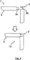
- Fig. 2 is a schematic cross-sectional view of two sandwich panels 2 of the construction kit 1 from Fig. 1 before (above) and after (below) the connection of the sandwich panels 2.
- the two sandwich panels 2 are fastened to one another via the plug regions 6a and mating plug regions 6b thereof, so that together, they form a monument component 12. This can be carried out before or after the impregnation with synthetic resin and the curing.
- Fig. 3 is a schematic cross-sectional view of a monument 10, which is constructed with the construction kit 1 from Fig. 1 and is fixed in position in a cabin 14 (not shown) of an aircraft 100.
- the monument 10 is a box-shaped fixture for an aircraft cabin 14.
- the monument can be for example a storage locker or a galley or the like.
- the solution according to the invention can be applied to various monuments which are to be positioned in an aircraft cabin 14 in a stationary manner.
- the monument 10 is composed of a plurality of monument components 12 and fastening rails 11.
- the fastening rails 11 are flush with an outer housing side.
- the monument components 12 can have been produced for example as in Fig. 2 and then connected by means of connecting structures (plug regions 6a and mating plug regions 6b') to the fastening rails 11.
- a fixing element 16 which is shown in Fig. 3 comprises a pivot bearing 18, on which connecting struts 19 are mounted, which in turn are each attached to the fastening rail 11 by means of a mounting foot 15.
- a tension rod 17 is mounted in the pivot bearing 18, which rod is rigidly connected to a structure of the aircraft 100.
- the mounting feet 15 are shaped so as to correspond to the holes 7 in the fastening rail 11.
- the mounting feet 15 can be fittings made of plastics material or metal, for example in the form of a slide such as is also used for fastening aircraft seats or similar components. Such fittings can be attached in a slidably displaceable manner for mounting on a rail.
- fittings there are fittings, the lower surface of which is shaped so as to precisely fit a portion consisting of holes 7 and slots 8 of the seat rail so that the fitting can be introduced into the receiving space 11 of the seat rail in a desired position.
- the fitting can be brought into a locked position, in which, due to the shape of the lower surface thereof, it cannot be lifted upwards out of the receiving space of the seat rail again (without shifting once more).
- the fitting can be secured for example by means of a setting screw or a lever device and thus rigidly connected to the seat rail.
- the connecting struts 19 can be formed for example from fibre-reinforced plastics material.
- the connecting struts 19 can be pultruded, hollow or solid carbon profiles, i.e. can consist of carbon-fibre-reinforced plastics material (CFRP).
- CFRP carbon-fibre-reinforced plastics material
- embodiments made of metal, such as aluminium or titanium, are provided in any case.
- the connecting struts 19 can be bonded for example to the pivot bearing 18 and to the mounting feet 15 and/or fastened by means of interference fits, screw-in connections or the like.
- the connecting struts 19 can comprise reinforcing structures, such as longitudinal ribs or the like.
- the pivot bearing 18 can be a simple metal component, such as are known to a person skilled in the art from various other applications.
- the tension rod 17 for example an extruded aluminium part, can be pivotally mounted in a hole in the pivot bearing in this case by means of a pin or the like. Furthermore, the tension rod 17 can have a symmetrical design, wherein a corresponding connection on the other side of the tension rod 17 is closed by the primary structure of the aircraft 100.
- Fig. 5 shows a schematic flow chart of a method M according to the invention for producing the construction kit 1 from Fig. 1 .
- the method M comprises arranging two cover panels 3 made of fibre composite semi-finished products around a core 4 made of a foam to form a sandwich structure.
- This step can further comprise sewing up the core 4 with a plurality of reinforcement fibres 5 and/or introducing a plurality of layers of reinforcement fibres 5.
- the density distribution of the reinforcement fibres 5 in the core 4 can be increased in the region of the plug regions 6a and/or the mating plug regions 6b.
- elongate hollow spaces 13 can additionally be formed in the core 4 of the sandwich structures, which hollow spaces each extend through the core 4 in a direction which is substantially parallel to the cover panels 3.
- the method further comprises inserting prefabricated panel connecting structures made of fibre composite semi-finished products in the sandwich structure to form plug regions or mating plug regions.
- the method can comprise plugging together a plurality of sandwich structures by means of the plug regions 6a and the mating plug regions 6b.
- This step can alternatively or additionally comprise introducing a fastening rail 11 made of a fibre composite semi-finished product comprising prefabricated rail-to-panel connecting structures.
- the rail-to-panel connecting structures can form plug regions 6a' or mating plug regions 6b'.
- this step can further comprise plugging together the fastening rail 11 with sandwich structures by means of the plug regions 6a' or mating plug regions 6b'.
- a fourth step under M4 the sandwich structure is impregnated with a synthetic resin, and in a fourth step under M5, the sandwich structure which is impregnated with synthetic resin is cured, and a sandwich panel 2 or an integral monument component 12 is thus formed.
Landscapes
- Engineering & Computer Science (AREA)
- Mechanical Engineering (AREA)
- Aviation & Aerospace Engineering (AREA)
- Chemical & Material Sciences (AREA)
- Composite Materials (AREA)
- Connection Of Plates (AREA)
Claims (14)
- Kit de construction (1) pour former une structure de logement d'un dispositif d'ameublement (10) pour une cabine (14) d'un véhicule, en particulier d'un aéronef ou engin spatial (100), comprenant une pluralité de panneaux sandwich formés de façon monobloc (2) qui ont chacun deux panneaux de revêtement (3), qui entourent une âme (4), et sont formés avec des structures de raccordement de panneau qui sont chacune sous la forme d'une région d'enfichage (6a) ou d'une région d'enfichage correspondante (6b), dans lequel la région d'enfichage correspondante (6b) est formée afin d'être complémentaire à la région d'enfichage (6a) de manière telle qu'une région d'enfichage (6a) d'un panneau sandwich (2) puisse être enfichée dans la région d'enfichage correspondante (6b) d'un autre panneau sandwich (2) pour raccorder les panneaux sandwich (2) pour former la structure de logement du dispositif d'ameublement (10), caractérisé en ce que :
le kit de construction (1) comprend au moins un rail d'arrimage (11), qui a un espace de réception (9) s'étendant le long de la direction longitudinale du rail d'arrimage (11), lequel espace est conçu pour recevoir et arrimer des pieds de montage (15) d'éléments de fixation (16) au rail d'arrimage (11) afin de fixer le dispositif d'ameublement (10) en position à l'intérieur de la cabine (14), dans lequel le rail d'arrimage (11) est formé avec des structures de raccordement de rail-à-panneau, qui sont chacune sous la forme d'une région d'enfichage (6a') ou d'une région d'enfichage correspondante (6b'), et dans lequel la région d'enfichage correspondante (6b') du rail d'arrimage (11) est formée afin d'être complémentaire à la région d'enfichage (6a) des panneaux sandwich (2), et la région d'enfichage (6a') du rail d'arrimage (11) est formée afin d'être complémentaire à la région d'enfichage correspondante (6b) des panneaux sandwich (2), pour que le rail d'arrimage (11) puisse être enfiché conjointement avec des panneaux sandwich (2). - Kit de construction (1) selon la revendication 1, dans lequel des fibres de renforcement (5) et/ou des couches de fibres de renforcement (5) sont prévues dans l'âme (4) des panneaux sandwich (2), dont la distribution de densité est augmentée au niveau des régions d'enfichage (6a) et/ou des régions d'enfichage correspondantes (6b).
- Kit de construction (1) selon la revendication 1 ou 2, dans lequel des espaces creux allongés (13) sont prévus dans l'âme (4) des panneaux sandwich (2), lesquels espaces creux s'étendent chacun à travers l'âme (4) dans une direction qui est sensiblement parallèle aux panneaux de revêtement (3).
- Kit de construction (1) selon au moins une des revendications précédentes, dans lequel au moins deux des panneaux sandwich (2) sont formés de façon monobloc l'un avec l'autre afin de former un composant de dispositif d'ameublement (12).
- Kit de construction (1) selon la revendication 1, dans lequel le rail d'arrimage (11) est formé avec une pluralité de trous régulièrement espacés (7) dans l'espace de réception (9), lesquels trous sont conçus pour recevoir et arrimer des pieds de montage (15) d'éléments de fixation (16) au rail d'arrimage (11).
- Kit de construction (1) selon au moins l'une des revendications 1 à 5, dans lequel le rail d'arrimage (11) est sous la forme d'un rail de siège.
- Kit de construction (1) selon au moins l'une des revendications 1 à 6, dans lequel le rail d'arrimage (11) est formé sensiblement à partir de matériau plastique renforcé de fibres, et au moins deux des panneaux sandwich (2) sont formés de façon monobloc conjointement avec les rails d'arrimage (11) situés entre ceux-ci pour former un composant de dispositif d'ameublement (12).
- Dispositif d'ameublement (10) pour une cabine (14) d'un véhicule, en particulier d'un aéronef ou engin spatial (100), comprenant une structure de logement qui est formée avec un kit de construction (1) selon au moins l'une des revendications 1 à 7.
- Aéronef ou engin spatial (100), comprenant une cabine (14), un dispositif d'ameublement (1) comprenant une structure de logement qui est formée avec un kit de construction (1) selon au moins l'une des revendications 1 à 7, et un élément de fixation (16) qui est raccordé à une structure de l'aéronef ou de l'engin spatial (100) et a des pieds de montage (15) qui sont montés à une distance les uns des autres dans le rail d'arrimage (11) du dispositif d'ameublement (10) et fixent le dispositif d'ameublement (10) dans une position à l'intérieur de la cabine (14) au moyen de l'élément de fixation (16).
- Procédé (M) pour produire un kit de construction (1) pour former la structure de logement d'un dispositif d'ameublement (10) pour une cabine (14) d'un véhicule, en particulier d'un aéronef ou engin spatial (100), comprenant les étapes de :l'agencement (M1) de deux panneaux de revêtement (3) faits de produits semi-finis en fibres composites autour d'une âme (4) faite d'une mousse pour former une structure sandwich ;l'insertion (M2) de structures de raccordement de panneau préfabriquées faites de produits semi-finis en fibres composites dans la structure sandwich pour former des régions d'enfichage (6a) ou régions d'enfichage correspondantes (6b) ;l'imprégnation (M4) de la structure sandwich avec une résine synthétique ;le durcissement (M5) de la structure sandwich qui est imprégnée avec de la résine synthétique et la formation d'un panneau sandwich (2) ;la fourniture d'une pluralité de panneaux sandwich (2) pour le kit de construction (1), dans lequel la région d'enfichage correspondante (6b) est formée afin d'être complémentaire à la région d'enfichage (6a) de manière telle qu'une région d'enfichage (6a) d'un panneau sandwich (2) puisse être enfichée dans la région d'enfichage correspondante (6b) d'un autre panneau sandwich (2) pour raccorder les panneaux sandwich (2) pour former la structure de logement du dispositif d'ameublement (10) ; etla fourniture d'au moins un rail d'arrimage (11), qui a un espace de réception (9) s'étendant le long de la direction longitudinale du rail d'arrimage (11), lequel espace est conçu pour recevoir et arrimer des pieds de montage (15) d'éléments de fixation (16) au rail d'arrimage (11) afin de fixer le dispositif d'ameublement (10) en position à l'intérieur de la cabine (14), dans lequel le rail d'arrimage (11) est formé avec des structures de raccordement de rail-à-panneau, qui sont chacune sous la forme d'une région d'enfichage (6a') ou d'une région d'enfichage correspondante (6b'), et dans lequel la région d'enfichage correspondante (6b') du rail d'arrimage (11) est formée afin d'être complémentaire à la région d'enfichage (6a) des panneaux sandwich (2), et la région d'enfichage (6a') du rail d'arrimage (11) est formée afin d'être complémentaire à la région d'enfichage correspondante (6b) des panneaux sandwich (2), pour que le rail d'arrimage (11) puisse être enfiché conjointement avec des panneaux sandwich (2).
- Procédé (M) selon la revendication 10, dans lequel le procédé comprend en outre l'étape de l'enfichage conjoint (M3) d'une pluralité de structures sandwich par l'intermédiaire des régions d'enfichage (6a) et des régions d'enfichage correspondantes (6b), et dans lequel le durcissement (M5) des structures sandwich qui sont imprégnées avec de la résine synthétique et enfichées conjointement comprend la formation d'un composant de dispositif d'ameublement monobloc (12).
- Procédé (M) selon la revendication 10 ou 11, dans lequel l'étape de l'enfichage conjoint (M3) comprend l'introduction d'un rail d'arrimage (11) fait d'un produit semi-fini en fibres composites ayant des structures de raccordement de rail-à-panneau préfabriquées, qui forment des régions d'enfichage (6a') ou des régions d'enfichage correspondantes (6b'), et l'enfichage du rail d'arrimage (11) conjointement avec des structures sandwich.
- Procédé (M) selon au moins l'une des revendications 10 à 12, dans lequel l'étape de l'agencement (M1) comprend la couture de l'âme (4) avec une pluralité de fibres de renforcement (5) et/ou l'introduction d'une pluralité de couches de fibres de renforcement (5), et dans lequel une distribution de densité des fibres de renforcement (5) dans l'âme (4) est augmentée au niveau des régions d'enfichage (6a) et/ou des régions d'enfichage correspondantes (6b).
- Procédé (M) selon au moins l'une des revendications 10 à 13, dans lequel l'étape de l'agencement (M1) comprend la formation d'espaces creux allongés (13) dans l'âme (4) des structures sandwich, lesquels espaces creux s'étendent chacun à travers l'âme (4) dans une direction qui est sensiblement parallèle aux plaques de revêtement (3).
Applications Claiming Priority (1)
| Application Number | Priority Date | Filing Date | Title |
|---|---|---|---|
| DE102015206713.0A DE102015206713A1 (de) | 2015-04-15 | 2015-04-15 | Bausatz und Verfahren für einen Gehäuseaufbau eines Monuments für eine Fahrzeugkabine |
Publications (2)
| Publication Number | Publication Date |
|---|---|
| EP3081489A1 EP3081489A1 (fr) | 2016-10-19 |
| EP3081489B1 true EP3081489B1 (fr) | 2019-12-11 |
Family
ID=55701841
Family Applications (1)
| Application Number | Title | Priority Date | Filing Date |
|---|---|---|---|
| EP16164440.6A Active EP3081489B1 (fr) | 2015-04-15 | 2016-04-08 | Kit de construction et procédé pour une structure de logement de borne pour une cabine de véhicule |
Country Status (3)
| Country | Link |
|---|---|
| US (1) | US10137989B2 (fr) |
| EP (1) | EP3081489B1 (fr) |
| DE (1) | DE102015206713A1 (fr) |
Families Citing this family (6)
| Publication number | Priority date | Publication date | Assignee | Title |
|---|---|---|---|---|
| EP3424823B1 (fr) * | 2016-02-29 | 2021-08-18 | Canon Denshi Kabushiki Kaisha | Satellite artificiel |
| DE102016210664A1 (de) * | 2016-06-15 | 2017-12-21 | Bayerische Motorenwerke Aktiengesellschaft | Verfahren zum Verbinden zweier Bauteile sowie Bauteilanordnung |
| CN106848954B (zh) * | 2017-03-24 | 2018-02-09 | 中国人民解放军国防科学技术大学 | 航天器用多功能结构电缆及其制备方法 |
| DE102017214340A1 (de) * | 2017-08-17 | 2019-02-21 | Airbus Operations Gmbh | Verfahren zur Herstellung eines Sandwichbauteils, Kern für ein Sandwichbauteil sowie Sandwichbauteil |
| DE202017106215U1 (de) * | 2017-10-13 | 2019-01-15 | Rehau Ag + Co | Rahmen für ein Gepäckfach eines Flugzeuges |
| CN112658600B (zh) * | 2020-11-30 | 2023-02-17 | 上海航天精密机械研究所 | 一种通用钣焊钛合金舱体加工方法 |
Citations (2)
| Publication number | Priority date | Publication date | Assignee | Title |
|---|---|---|---|---|
| US20020144767A1 (en) * | 2001-04-06 | 2002-10-10 | Johnson David W. | Method of clinching the top and bottom ends of Z-axis fibers into the respective top and bottom surfaces of a composite laminate |
| US20120248245A1 (en) * | 2009-03-24 | 2012-10-04 | Airbus Operations Gmbh | Convertible monuments |
Family Cites Families (46)
| Publication number | Priority date | Publication date | Assignee | Title |
|---|---|---|---|---|
| US5445861A (en) * | 1992-09-04 | 1995-08-29 | The Boeing Company | Lightweight honeycomb panel structure |
| GB2340065B (en) * | 1996-02-24 | 2000-06-28 | Eurocopter Deutschland | Method of achieving a glued connection of planar or sheet parts |
| DE19654672A1 (de) * | 1996-07-30 | 1998-02-05 | Swap Technology Ag | Wellkarton-Wabenkern, Verfahren und Vorrichtung zu seiner Herstellung |
| DK174563B1 (da) * | 1996-09-06 | 2003-06-10 | Daimlerchrysler Rail Systems | Beklædningsplade samt fremgangsmåde til fremstilling af en sådan beklædningsplade |
| US6284089B1 (en) * | 1997-12-23 | 2001-09-04 | The Boeing Company | Thermoplastic seam welds |
| CO4870729A1 (es) * | 1998-02-09 | 1999-12-27 | Steven C Meyerson | Paneles de construccion |
| US5974784A (en) * | 1998-10-12 | 1999-11-02 | Nu-Chem, Inc. | Insulative shield, particularly for automotive exhaust components |
| SE517183C2 (sv) * | 2000-01-24 | 2002-04-23 | Valinge Aluminium Ab | Låssystem för mekanisk hopfogning av golvskivor, golvskiva försedd med låssystemet och metod för framställning av sådana golvskivor |
| SE518184C2 (sv) * | 2000-03-31 | 2002-09-03 | Perstorp Flooring Ab | Golvbeläggningsmaterial innefattande skivformiga golvelement vilka sammanfogas med hjälp av sammankopplingsorgan |
| AT411374B (de) * | 2000-06-06 | 2003-12-29 | Kaindl M | Belag, verkleidung od.dgl., paneele für dessen bildung sowie verfahren und gerät zur herstellung der paneele |
| US20020014302A1 (en) | 2000-07-13 | 2002-02-07 | Kazak Composites, Incorporated | Method for incorporating rigid elements into the core of composite structural members in a pultrusion process |
| US6823638B2 (en) * | 2001-06-27 | 2004-11-30 | Pergo (Europe) Ab | High friction joint, and interlocking joints for forming a generally planar surface, and method of assembling the same |
| US8028486B2 (en) * | 2001-07-27 | 2011-10-04 | Valinge Innovation Ab | Floor panel with sealing means |
| SE525657C2 (sv) * | 2002-04-08 | 2005-03-29 | Vaelinge Innovation Ab | Golvskivor för flytande golv framställda av åtminstone två olika materialskikt samt halvfabrikat för tillverkning av golvskivor |
| DE10243196B4 (de) * | 2002-09-18 | 2007-03-22 | Kaindl Flooring Gmbh | Paneele mit Verbindungsklammer |
| US7281685B2 (en) * | 2004-08-20 | 2007-10-16 | Airbus Deutschland Gmbh | Flush-top seat mounting rail for passenger aircraft |
| US7988809B2 (en) * | 2004-09-01 | 2011-08-02 | Hexcel Corporation | Aircraft floor and interior panels using edge coated honeycomb |
| US7641414B1 (en) * | 2004-09-04 | 2010-01-05 | Joyce Jared L | Furniture and joint systems |
| US20060080927A1 (en) * | 2004-10-15 | 2006-04-20 | Werzalit Ag & Co. Kg | Profiled element for establishing tongue and groove connections, and laminate thereof |
| US8215078B2 (en) * | 2005-02-15 | 2012-07-10 | Välinge Innovation Belgium BVBA | Building panel with compressed edges and method of making same |
| US8769904B1 (en) * | 2005-03-24 | 2014-07-08 | Barrette Outdoor Living, Inc. | Interlock panel, panel assembly, and method for shipping |
| ITMI20051199A1 (it) * | 2005-06-24 | 2006-12-25 | Intersider Acciai S P A | Piastrella per rivestimenti in metallo metodo per la produzione e rivestimenti relativi |
| FR2891239B1 (fr) * | 2005-09-28 | 2009-04-17 | Airbus France Sas | Panneau de plancher et installation pour la fixation d'elements d'amenagement comportant de tels panneaux |
| DE102005054890B4 (de) | 2005-11-17 | 2014-08-21 | Airbus Operations Gmbh | Flugzeugrumpfstruktur mit einer Passagierkabine und einer Befestigungsstruktur zur Fixierung von Inneneinrichtungskomponenten in der Passagierkabine |
| SE530653C2 (sv) * | 2006-01-12 | 2008-07-29 | Vaelinge Innovation Ab | Fuktsäker golvskiva samt golv med ett elastiskt ytskikt omfattande ett dekorativt spår |
| US7601654B2 (en) * | 2006-03-30 | 2009-10-13 | Honeywell International Inc. | Molded ballistic panel with enhanced structural performance |
| NL1031771C2 (nl) * | 2006-05-08 | 2007-11-09 | Fits Holding B V | Het koppelen van thermoplastische sandwichpanelen. |
| DE102007007832A1 (de) * | 2007-02-16 | 2008-11-20 | Kaindl Flooring Gmbh | Verkleidungspaneel |
| US8016230B2 (en) * | 2007-05-11 | 2011-09-13 | The Boeing Company | Fastner-free primary structural joint for sandwich panels |
| JP4699425B2 (ja) * | 2007-06-22 | 2011-06-08 | 株式会社ジャムコ | サンドイッチパネル |
| DE102007032233B4 (de) | 2007-07-11 | 2014-07-10 | Airbus Operations Gmbh | Installationssystem für ein Flugzeug |
| FR2921076B1 (fr) * | 2007-09-18 | 2010-04-02 | Roy Guy Le | Panneau a forte resistance structurelle, dispositif et procede pour fabriquer un tel panneau |
| NL2002289C2 (en) * | 2008-12-04 | 2010-06-07 | Gtm Holding B V | Sandwich panel, support member for use in a sandwich panel and aircraft provided with such a sandwich panel. |
| BE1018389A3 (nl) * | 2008-12-17 | 2010-10-05 | Unilin Bvba | Samengesteld element, meerlagige plaat en paneelvormig element voor het vormen van zulk samengesteld element. |
| DE102008064120A1 (de) * | 2008-12-19 | 2010-07-01 | Airbus Deutschland Gmbh | Montagesystem zur Befestigung eines Strukturmonuments in einer gewünschten Position in einer Flugzeugkabine |
| DE102009034406A1 (de) * | 2009-07-23 | 2011-02-03 | Airbus Operations Gmbh | Monument für eine Kabine eines Fahrzeugs |
| JP2011131628A (ja) * | 2009-12-22 | 2011-07-07 | Kawasaki Heavy Ind Ltd | 鉄道車両の内装構造 |
| DE102010011219A1 (de) * | 2010-03-09 | 2011-09-15 | Performa Möbel und Design GmbH | Montagesystem zur beweglichen Anbringung eines Bauteils an einer Wand |
| DE102010047385A1 (de) * | 2010-10-02 | 2012-04-05 | Tutech Innovation Gmbh | Halterung für Inneneinrichtungskomponenten in Flugzeugkabinen |
| KR101219878B1 (ko) * | 2010-12-29 | 2013-01-09 | 전남대학교산학협력단 | 트러스 구조의 심재를 구비한 샌드위치 패널의 제조방법 |
| BE1019891A5 (nl) * | 2011-03-28 | 2013-02-05 | Unilin Bvba | Samengesteld element en rugwandconstructie hierbij toegepast. |
| WO2012149379A2 (fr) * | 2011-04-28 | 2012-11-01 | Zin Technologies, Inc. | Structure composite collée et cousue |
| CN103906623A (zh) * | 2011-10-31 | 2014-07-02 | 仓敷纺绩株式会社 | 层叠结构体 |
| WO2013084023A1 (fr) * | 2011-12-05 | 2013-06-13 | Csir | Objet ignifugé et son procédé de fabrication |
| US8776698B2 (en) * | 2012-10-08 | 2014-07-15 | Advanced Composite Structures, Llc | Composite air cargo pallet |
| WO2015095396A1 (fr) * | 2013-12-17 | 2015-06-25 | C&D Zodiac, Inc. | Ensemble panneau isolé par un aérogel polyimide |
-
2015
- 2015-04-15 DE DE102015206713.0A patent/DE102015206713A1/de not_active Withdrawn
-
2016
- 2016-04-08 EP EP16164440.6A patent/EP3081489B1/fr active Active
- 2016-04-12 US US15/096,388 patent/US10137989B2/en active Active
Patent Citations (2)
| Publication number | Priority date | Publication date | Assignee | Title |
|---|---|---|---|---|
| US20020144767A1 (en) * | 2001-04-06 | 2002-10-10 | Johnson David W. | Method of clinching the top and bottom ends of Z-axis fibers into the respective top and bottom surfaces of a composite laminate |
| US20120248245A1 (en) * | 2009-03-24 | 2012-10-04 | Airbus Operations Gmbh | Convertible monuments |
Also Published As
| Publication number | Publication date |
|---|---|
| EP3081489A1 (fr) | 2016-10-19 |
| US10137989B2 (en) | 2018-11-27 |
| DE102015206713A1 (de) | 2016-10-20 |
| US20160304206A1 (en) | 2016-10-20 |
Similar Documents
| Publication | Publication Date | Title |
|---|---|---|
| EP3081489B1 (fr) | Kit de construction et procédé pour une structure de logement de borne pour une cabine de véhicule | |
| US9902483B2 (en) | Window panel for an airframe and method of producing same | |
| US8424804B2 (en) | Attachment arrangement for attaching a component to the fuselage of an aircraft, aircraft and method for constructing an attachment arrangement | |
| RU2641959C2 (ru) | Композитный шляпообразный профиль усиления, композитные усиленные шляпообразными профилями гермоперегородки и способы их изготовления | |
| RU2641026C2 (ru) | Силовые кессонные конструкции и способы их получения | |
| US8240606B2 (en) | Integrated aircraft floor with longitudinal beams | |
| US10137974B2 (en) | Monument for a cabin of a vehicle, and fastening arrangement | |
| RU2664524C2 (ru) | Слоистый композитный радиусный заполнитель с элементом заполнителя геометрической формы и способ его формирования | |
| US8096504B2 (en) | Integrated aircraft structure in composite material | |
| US9359078B2 (en) | Aircraft galley monument structure | |
| RU2646400C2 (ru) | Способ и система изготовления композитных конструкций с заполнителями зазора из материала на основе рубленого волокна | |
| CN106275370B (zh) | 加强机身部件以及用于制造加强机身部件的方法和装置 | |
| US11800641B2 (en) | Composite panel comprising an integrated electrical circuit and manufacturing method thereof | |
| US8814091B2 (en) | Floor made out of composite material and process for manufacturing such a floor | |
| US20160101576A1 (en) | Method for manufacturing a fibre composite component, fibre composite component, and structural component for an aircraft or spacecraft | |
| JP2012501889A (ja) | 補強構造が統合されたサンドイッチパネル及びその製造のための方法 | |
| BRPI0806718A2 (pt) | elemento de revestimento como parte de uma fuselagem de aeronave | |
| CN110901881A (zh) | 用于载具的地板系统 | |
| EP3081449B1 (fr) | Construction de plancher pour un véhicule | |
| US20090242150A1 (en) | Curtain support assembly, in a framework design, in a cabin of a vehicle | |
| US8372498B2 (en) | Composite core densification | |
| CN101203374B (zh) | 用于生产大致壳状的部件的工艺 | |
| CN113955071A (zh) | 飞行器机身及其成型方法、飞行器 | |
| EP2818403B1 (fr) | Composant structural d'aéronef localement renforcé | |
| HK1228865A1 (en) | Interior trim part and set of prefabricated parts for an aircraft cell |
Legal Events
| Date | Code | Title | Description |
|---|---|---|---|
| PUAI | Public reference made under article 153(3) epc to a published international application that has entered the european phase |
Free format text: ORIGINAL CODE: 0009012 |
|
| AK | Designated contracting states |
Kind code of ref document: A1 Designated state(s): AL AT BE BG CH CY CZ DE DK EE ES FI FR GB GR HR HU IE IS IT LI LT LU LV MC MK MT NL NO PL PT RO RS SE SI SK SM TR |
|
| AX | Request for extension of the european patent |
Extension state: BA ME |
|
| STAA | Information on the status of an ep patent application or granted ep patent |
Free format text: STATUS: REQUEST FOR EXAMINATION WAS MADE |
|
| 17P | Request for examination filed |
Effective date: 20170407 |
|
| RBV | Designated contracting states (corrected) |
Designated state(s): AL AT BE BG CH CY CZ DE DK EE ES FI FR GB GR HR HU IE IS IT LI LT LU LV MC MK MT NL NO PL PT RO RS SE SI SK SM TR |
|
| STAA | Information on the status of an ep patent application or granted ep patent |
Free format text: STATUS: EXAMINATION IS IN PROGRESS |
|
| 17Q | First examination report despatched |
Effective date: 20180309 |
|
| GRAP | Despatch of communication of intention to grant a patent |
Free format text: ORIGINAL CODE: EPIDOSNIGR1 |
|
| STAA | Information on the status of an ep patent application or granted ep patent |
Free format text: STATUS: GRANT OF PATENT IS INTENDED |
|
| INTG | Intention to grant announced |
Effective date: 20190726 |
|
| RIN1 | Information on inventor provided before grant (corrected) |
Inventor name: VON AHLEN, TIM Inventor name: FENNEN, ANSGAR JOSEF Inventor name: LUEBBERING, CHRISTIAN Inventor name: HIEBING, DANIEL Inventor name: BAJORAT, FALK |
|
| GRAS | Grant fee paid |
Free format text: ORIGINAL CODE: EPIDOSNIGR3 |
|
| GRAA | (expected) grant |
Free format text: ORIGINAL CODE: 0009210 |
|
| STAA | Information on the status of an ep patent application or granted ep patent |
Free format text: STATUS: THE PATENT HAS BEEN GRANTED |
|
| AK | Designated contracting states |
Kind code of ref document: B1 Designated state(s): AL AT BE BG CH CY CZ DE DK EE ES FI FR GB GR HR HU IE IS IT LI LT LU LV MC MK MT NL NO PL PT RO RS SE SI SK SM TR |
|
| REG | Reference to a national code |
Ref country code: GB Ref legal event code: FG4D |
|
| REG | Reference to a national code |
Ref country code: CH Ref legal event code: EP |
|
| REG | Reference to a national code |
Ref country code: AT Ref legal event code: REF Ref document number: 1211950 Country of ref document: AT Kind code of ref document: T Effective date: 20191215 |
|
| REG | Reference to a national code |
Ref country code: DE Ref legal event code: R096 Ref document number: 602016025870 Country of ref document: DE |
|
| REG | Reference to a national code |
Ref country code: IE Ref legal event code: FG4D |
|
| REG | Reference to a national code |
Ref country code: NL Ref legal event code: MP Effective date: 20191211 |
|
| REG | Reference to a national code |
Ref country code: LT Ref legal event code: MG4D |
|
| PG25 | Lapsed in a contracting state [announced via postgrant information from national office to epo] |
Ref country code: SE Free format text: LAPSE BECAUSE OF FAILURE TO SUBMIT A TRANSLATION OF THE DESCRIPTION OR TO PAY THE FEE WITHIN THE PRESCRIBED TIME-LIMIT Effective date: 20191211 Ref country code: LV Free format text: LAPSE BECAUSE OF FAILURE TO SUBMIT A TRANSLATION OF THE DESCRIPTION OR TO PAY THE FEE WITHIN THE PRESCRIBED TIME-LIMIT Effective date: 20191211 Ref country code: BG Free format text: LAPSE BECAUSE OF FAILURE TO SUBMIT A TRANSLATION OF THE DESCRIPTION OR TO PAY THE FEE WITHIN THE PRESCRIBED TIME-LIMIT Effective date: 20200311 Ref country code: FI Free format text: LAPSE BECAUSE OF FAILURE TO SUBMIT A TRANSLATION OF THE DESCRIPTION OR TO PAY THE FEE WITHIN THE PRESCRIBED TIME-LIMIT Effective date: 20191211 Ref country code: GR Free format text: LAPSE BECAUSE OF FAILURE TO SUBMIT A TRANSLATION OF THE DESCRIPTION OR TO PAY THE FEE WITHIN THE PRESCRIBED TIME-LIMIT Effective date: 20200312 Ref country code: NO Free format text: LAPSE BECAUSE OF FAILURE TO SUBMIT A TRANSLATION OF THE DESCRIPTION OR TO PAY THE FEE WITHIN THE PRESCRIBED TIME-LIMIT Effective date: 20200311 Ref country code: LT Free format text: LAPSE BECAUSE OF FAILURE TO SUBMIT A TRANSLATION OF THE DESCRIPTION OR TO PAY THE FEE WITHIN THE PRESCRIBED TIME-LIMIT Effective date: 20191211 |
|
| PG25 | Lapsed in a contracting state [announced via postgrant information from national office to epo] |
Ref country code: RS Free format text: LAPSE BECAUSE OF FAILURE TO SUBMIT A TRANSLATION OF THE DESCRIPTION OR TO PAY THE FEE WITHIN THE PRESCRIBED TIME-LIMIT Effective date: 20191211 Ref country code: HR Free format text: LAPSE BECAUSE OF FAILURE TO SUBMIT A TRANSLATION OF THE DESCRIPTION OR TO PAY THE FEE WITHIN THE PRESCRIBED TIME-LIMIT Effective date: 20191211 |
|
| PG25 | Lapsed in a contracting state [announced via postgrant information from national office to epo] |
Ref country code: AL Free format text: LAPSE BECAUSE OF FAILURE TO SUBMIT A TRANSLATION OF THE DESCRIPTION OR TO PAY THE FEE WITHIN THE PRESCRIBED TIME-LIMIT Effective date: 20191211 |
|
| PG25 | Lapsed in a contracting state [announced via postgrant information from national office to epo] |
Ref country code: ES Free format text: LAPSE BECAUSE OF FAILURE TO SUBMIT A TRANSLATION OF THE DESCRIPTION OR TO PAY THE FEE WITHIN THE PRESCRIBED TIME-LIMIT Effective date: 20191211 Ref country code: RO Free format text: LAPSE BECAUSE OF FAILURE TO SUBMIT A TRANSLATION OF THE DESCRIPTION OR TO PAY THE FEE WITHIN THE PRESCRIBED TIME-LIMIT Effective date: 20191211 Ref country code: NL Free format text: LAPSE BECAUSE OF FAILURE TO SUBMIT A TRANSLATION OF THE DESCRIPTION OR TO PAY THE FEE WITHIN THE PRESCRIBED TIME-LIMIT Effective date: 20191211 Ref country code: CZ Free format text: LAPSE BECAUSE OF FAILURE TO SUBMIT A TRANSLATION OF THE DESCRIPTION OR TO PAY THE FEE WITHIN THE PRESCRIBED TIME-LIMIT Effective date: 20191211 Ref country code: EE Free format text: LAPSE BECAUSE OF FAILURE TO SUBMIT A TRANSLATION OF THE DESCRIPTION OR TO PAY THE FEE WITHIN THE PRESCRIBED TIME-LIMIT Effective date: 20191211 Ref country code: PT Free format text: LAPSE BECAUSE OF FAILURE TO SUBMIT A TRANSLATION OF THE DESCRIPTION OR TO PAY THE FEE WITHIN THE PRESCRIBED TIME-LIMIT Effective date: 20200506 |
|
| PG25 | Lapsed in a contracting state [announced via postgrant information from national office to epo] |
Ref country code: SK Free format text: LAPSE BECAUSE OF FAILURE TO SUBMIT A TRANSLATION OF THE DESCRIPTION OR TO PAY THE FEE WITHIN THE PRESCRIBED TIME-LIMIT Effective date: 20191211 Ref country code: IS Free format text: LAPSE BECAUSE OF FAILURE TO SUBMIT A TRANSLATION OF THE DESCRIPTION OR TO PAY THE FEE WITHIN THE PRESCRIBED TIME-LIMIT Effective date: 20200411 Ref country code: SM Free format text: LAPSE BECAUSE OF FAILURE TO SUBMIT A TRANSLATION OF THE DESCRIPTION OR TO PAY THE FEE WITHIN THE PRESCRIBED TIME-LIMIT Effective date: 20191211 |
|
| REG | Reference to a national code |
Ref country code: DE Ref legal event code: R097 Ref document number: 602016025870 Country of ref document: DE |
|
| REG | Reference to a national code |
Ref country code: AT Ref legal event code: MK05 Ref document number: 1211950 Country of ref document: AT Kind code of ref document: T Effective date: 20191211 |
|
| PLBE | No opposition filed within time limit |
Free format text: ORIGINAL CODE: 0009261 |
|
| STAA | Information on the status of an ep patent application or granted ep patent |
Free format text: STATUS: NO OPPOSITION FILED WITHIN TIME LIMIT |
|
| PG25 | Lapsed in a contracting state [announced via postgrant information from national office to epo] |
Ref country code: DK Free format text: LAPSE BECAUSE OF FAILURE TO SUBMIT A TRANSLATION OF THE DESCRIPTION OR TO PAY THE FEE WITHIN THE PRESCRIBED TIME-LIMIT Effective date: 20191211 |
|
| 26N | No opposition filed |
Effective date: 20200914 |
|
| PG25 | Lapsed in a contracting state [announced via postgrant information from national office to epo] |
Ref country code: MC Free format text: LAPSE BECAUSE OF FAILURE TO SUBMIT A TRANSLATION OF THE DESCRIPTION OR TO PAY THE FEE WITHIN THE PRESCRIBED TIME-LIMIT Effective date: 20191211 Ref country code: AT Free format text: LAPSE BECAUSE OF FAILURE TO SUBMIT A TRANSLATION OF THE DESCRIPTION OR TO PAY THE FEE WITHIN THE PRESCRIBED TIME-LIMIT Effective date: 20191211 Ref country code: SI Free format text: LAPSE BECAUSE OF FAILURE TO SUBMIT A TRANSLATION OF THE DESCRIPTION OR TO PAY THE FEE WITHIN THE PRESCRIBED TIME-LIMIT Effective date: 20191211 |
|
| REG | Reference to a national code |
Ref country code: CH Ref legal event code: PL |
|
| PG25 | Lapsed in a contracting state [announced via postgrant information from national office to epo] |
Ref country code: IT Free format text: LAPSE BECAUSE OF FAILURE TO SUBMIT A TRANSLATION OF THE DESCRIPTION OR TO PAY THE FEE WITHIN THE PRESCRIBED TIME-LIMIT Effective date: 20191211 Ref country code: CH Free format text: LAPSE BECAUSE OF NON-PAYMENT OF DUE FEES Effective date: 20200430 Ref country code: LI Free format text: LAPSE BECAUSE OF NON-PAYMENT OF DUE FEES Effective date: 20200430 Ref country code: LU Free format text: LAPSE BECAUSE OF NON-PAYMENT OF DUE FEES Effective date: 20200408 |
|
| REG | Reference to a national code |
Ref country code: BE Ref legal event code: MM Effective date: 20200430 |
|
| PG25 | Lapsed in a contracting state [announced via postgrant information from national office to epo] |
Ref country code: PL Free format text: LAPSE BECAUSE OF FAILURE TO SUBMIT A TRANSLATION OF THE DESCRIPTION OR TO PAY THE FEE WITHIN THE PRESCRIBED TIME-LIMIT Effective date: 20191211 Ref country code: BE Free format text: LAPSE BECAUSE OF NON-PAYMENT OF DUE FEES Effective date: 20200430 |
|
| PG25 | Lapsed in a contracting state [announced via postgrant information from national office to epo] |
Ref country code: IE Free format text: LAPSE BECAUSE OF NON-PAYMENT OF DUE FEES Effective date: 20200408 |
|
| PGFP | Annual fee paid to national office [announced via postgrant information from national office to epo] |
Ref country code: DE Payment date: 20210420 Year of fee payment: 6 |
|
| PG25 | Lapsed in a contracting state [announced via postgrant information from national office to epo] |
Ref country code: TR Free format text: LAPSE BECAUSE OF FAILURE TO SUBMIT A TRANSLATION OF THE DESCRIPTION OR TO PAY THE FEE WITHIN THE PRESCRIBED TIME-LIMIT Effective date: 20191211 Ref country code: MT Free format text: LAPSE BECAUSE OF FAILURE TO SUBMIT A TRANSLATION OF THE DESCRIPTION OR TO PAY THE FEE WITHIN THE PRESCRIBED TIME-LIMIT Effective date: 20191211 Ref country code: CY Free format text: LAPSE BECAUSE OF FAILURE TO SUBMIT A TRANSLATION OF THE DESCRIPTION OR TO PAY THE FEE WITHIN THE PRESCRIBED TIME-LIMIT Effective date: 20191211 |
|
| PG25 | Lapsed in a contracting state [announced via postgrant information from national office to epo] |
Ref country code: MK Free format text: LAPSE BECAUSE OF FAILURE TO SUBMIT A TRANSLATION OF THE DESCRIPTION OR TO PAY THE FEE WITHIN THE PRESCRIBED TIME-LIMIT Effective date: 20191211 |
|
| REG | Reference to a national code |
Ref country code: DE Ref legal event code: R119 Ref document number: 602016025870 Country of ref document: DE |
|
| PG25 | Lapsed in a contracting state [announced via postgrant information from national office to epo] |
Ref country code: DE Free format text: LAPSE BECAUSE OF NON-PAYMENT OF DUE FEES Effective date: 20221103 |
|
| PGFP | Annual fee paid to national office [announced via postgrant information from national office to epo] |
Ref country code: GB Payment date: 20230419 Year of fee payment: 8 |
|
| GBPC | Gb: european patent ceased through non-payment of renewal fee |
Effective date: 20240408 |
|
| PG25 | Lapsed in a contracting state [announced via postgrant information from national office to epo] |
Ref country code: GB Free format text: LAPSE BECAUSE OF NON-PAYMENT OF DUE FEES Effective date: 20240408 |
|
| PG25 | Lapsed in a contracting state [announced via postgrant information from national office to epo] |
Ref country code: GB Free format text: LAPSE BECAUSE OF NON-PAYMENT OF DUE FEES Effective date: 20240408 |
|
| PGFP | Annual fee paid to national office [announced via postgrant information from national office to epo] |
Ref country code: FR Payment date: 20250425 Year of fee payment: 10 |