EP3081615A2 - Element d'etancheification pour un joint comprenant au moins une couche d'une premiere masse comprenant du bitume et d'une seconde masse comprenant du bitume - Google Patents
Element d'etancheification pour un joint comprenant au moins une couche d'une premiere masse comprenant du bitume et d'une seconde masse comprenant du bitume Download PDFInfo
- Publication number
- EP3081615A2 EP3081615A2 EP16165251.6A EP16165251A EP3081615A2 EP 3081615 A2 EP3081615 A2 EP 3081615A2 EP 16165251 A EP16165251 A EP 16165251A EP 3081615 A2 EP3081615 A2 EP 3081615A2
- Authority
- EP
- European Patent Office
- Prior art keywords
- mass
- joint
- nozzle
- layer
- weight
- Prior art date
- Legal status (The legal status is an assumption and is not a legal conclusion. Google has not performed a legal analysis and makes no representation as to the accuracy of the status listed.)
- Granted
Links
Images
Classifications
-
- C—CHEMISTRY; METALLURGY
- C08—ORGANIC MACROMOLECULAR COMPOUNDS; THEIR PREPARATION OR CHEMICAL WORKING-UP; COMPOSITIONS BASED THEREON
- C08L—COMPOSITIONS OF MACROMOLECULAR COMPOUNDS
- C08L95/00—Compositions of bituminous materials, e.g. asphalt, tar, pitch
-
- B—PERFORMING OPERATIONS; TRANSPORTING
- B05—SPRAYING OR ATOMISING IN GENERAL; APPLYING FLUENT MATERIALS TO SURFACES, IN GENERAL
- B05B—SPRAYING APPARATUS; ATOMISING APPARATUS; NOZZLES
- B05B1/00—Nozzles, spray heads or other outlets, with or without auxiliary devices such as valves, heating means
-
- C—CHEMISTRY; METALLURGY
- C04—CEMENTS; CONCRETE; ARTIFICIAL STONE; CERAMICS; REFRACTORIES
- C04B—LIME, MAGNESIA; SLAG; CEMENTS; COMPOSITIONS THEREOF, e.g. MORTARS, CONCRETE OR LIKE BUILDING MATERIALS; ARTIFICIAL STONE; CERAMICS; REFRACTORIES; TREATMENT OF NATURAL STONE
- C04B26/00—Compositions of mortars, concrete or artificial stone, containing only organic binders, e.g. polymer or resin concrete
- C04B26/02—Macromolecular compounds
- C04B26/26—Bituminous materials, e.g. tar, pitch
-
- E—FIXED CONSTRUCTIONS
- E01—CONSTRUCTION OF ROADS, RAILWAYS, OR BRIDGES
- E01C—CONSTRUCTION OF, OR SURFACES FOR, ROADS, SPORTS GROUNDS, OR THE LIKE; MACHINES OR AUXILIARY TOOLS FOR CONSTRUCTION OR REPAIR
- E01C11/00—Details of pavings
- E01C11/02—Arrangement or construction of joints; Methods of making joints; Packing for joints
- E01C11/04—Arrangement or construction of joints; Methods of making joints; Packing for joints for cement concrete paving
- E01C11/10—Packing of plastic or elastic materials, e.g. wood, resin
- E01C11/103—Joints with packings prepared only in situ; Materials therefor
-
- E—FIXED CONSTRUCTIONS
- E01—CONSTRUCTION OF ROADS, RAILWAYS, OR BRIDGES
- E01C—CONSTRUCTION OF, OR SURFACES FOR, ROADS, SPORTS GROUNDS, OR THE LIKE; MACHINES OR AUXILIARY TOOLS FOR CONSTRUCTION OR REPAIR
- E01C23/00—Auxiliary devices or arrangements for constructing, repairing, reconditioning, or taking-up road or like surfaces
- E01C23/06—Devices or arrangements for working the finished surface; Devices for repairing or reconditioning the surface of damaged paving; Recycling in place or on the road
- E01C23/09—Devices or arrangements for working the finished surface; Devices for repairing or reconditioning the surface of damaged paving; Recycling in place or on the road for forming cuts, grooves, or recesses, e.g. for making joints or channels for markings, for cutting-out sections to be removed; for cleaning, treating, or filling cuts, grooves, recesses, or fissures; for trimming paving edges
- E01C23/0966—Devices or arrangements for working the finished surface; Devices for repairing or reconditioning the surface of damaged paving; Recycling in place or on the road for forming cuts, grooves, or recesses, e.g. for making joints or channels for markings, for cutting-out sections to be removed; for cleaning, treating, or filling cuts, grooves, recesses, or fissures; for trimming paving edges for filling or priming, with or without working the surface of the filling or applying particulate material thereto, e.g. for filling the joints of stone-sett paving
- E01C23/0973—Devices or arrangements for working the finished surface; Devices for repairing or reconditioning the surface of damaged paving; Recycling in place or on the road for forming cuts, grooves, or recesses, e.g. for making joints or channels for markings, for cutting-out sections to be removed; for cleaning, treating, or filling cuts, grooves, recesses, or fissures; for trimming paving edges for filling or priming, with or without working the surface of the filling or applying particulate material thereto, e.g. for filling the joints of stone-sett paving with liquid or semi-liquid materials, e.g. crack sealants
-
- C—CHEMISTRY; METALLURGY
- C04—CEMENTS; CONCRETE; ARTIFICIAL STONE; CERAMICS; REFRACTORIES
- C04B—LIME, MAGNESIA; SLAG; CEMENTS; COMPOSITIONS THEREOF, e.g. MORTARS, CONCRETE OR LIKE BUILDING MATERIALS; ARTIFICIAL STONE; CERAMICS; REFRACTORIES; TREATMENT OF NATURAL STONE
- C04B2111/00—Mortars, concrete or artificial stone or mixtures to prepare them, characterised by specific function, property or use
- C04B2111/00474—Uses not provided for elsewhere in C04B2111/00
- C04B2111/00663—Uses not provided for elsewhere in C04B2111/00 as filling material for cavities or the like
- C04B2111/00672—Pointing or jointing materials
-
- C—CHEMISTRY; METALLURGY
- C04—CEMENTS; CONCRETE; ARTIFICIAL STONE; CERAMICS; REFRACTORIES
- C04B—LIME, MAGNESIA; SLAG; CEMENTS; COMPOSITIONS THEREOF, e.g. MORTARS, CONCRETE OR LIKE BUILDING MATERIALS; ARTIFICIAL STONE; CERAMICS; REFRACTORIES; TREATMENT OF NATURAL STONE
- C04B2111/00—Mortars, concrete or artificial stone or mixtures to prepare them, characterised by specific function, property or use
- C04B2111/00474—Uses not provided for elsewhere in C04B2111/00
- C04B2111/0075—Uses not provided for elsewhere in C04B2111/00 for road construction
-
- C—CHEMISTRY; METALLURGY
- C04—CEMENTS; CONCRETE; ARTIFICIAL STONE; CERAMICS; REFRACTORIES
- C04B—LIME, MAGNESIA; SLAG; CEMENTS; COMPOSITIONS THEREOF, e.g. MORTARS, CONCRETE OR LIKE BUILDING MATERIALS; ARTIFICIAL STONE; CERAMICS; REFRACTORIES; TREATMENT OF NATURAL STONE
- C04B2111/00—Mortars, concrete or artificial stone or mixtures to prepare them, characterised by specific function, property or use
- C04B2111/72—Repairing or restoring existing buildings or building materials
-
- C—CHEMISTRY; METALLURGY
- C08—ORGANIC MACROMOLECULAR COMPOUNDS; THEIR PREPARATION OR CHEMICAL WORKING-UP; COMPOSITIONS BASED THEREON
- C08K—Use of inorganic or non-macromolecular organic substances as compounding ingredients
- C08K3/00—Use of inorganic substances as compounding ingredients
- C08K3/18—Oxygen-containing compounds, e.g. metal carbonyls
- C08K3/20—Oxides; Hydroxides
- C08K3/22—Oxides; Hydroxides of metals
- C08K2003/2237—Oxides; Hydroxides of metals of titanium
- C08K2003/2241—Titanium dioxide
-
- E—FIXED CONSTRUCTIONS
- E02—HYDRAULIC ENGINEERING; FOUNDATIONS; SOIL SHIFTING
- E02D—FOUNDATIONS; EXCAVATIONS; EMBANKMENTS; UNDERGROUND OR UNDERWATER STRUCTURES
- E02D31/00—Protective arrangements for foundations or foundation structures; Ground foundation measures for protecting the soil or the subsoil water, e.g. preventing or counteracting oil pollution
-
- Y—GENERAL TAGGING OF NEW TECHNOLOGICAL DEVELOPMENTS; GENERAL TAGGING OF CROSS-SECTIONAL TECHNOLOGIES SPANNING OVER SEVERAL SECTIONS OF THE IPC; TECHNICAL SUBJECTS COVERED BY FORMER USPC CROSS-REFERENCE ART COLLECTIONS [XRACs] AND DIGESTS
- Y02—TECHNOLOGIES OR APPLICATIONS FOR MITIGATION OR ADAPTATION AGAINST CLIMATE CHANGE
- Y02W—CLIMATE CHANGE MITIGATION TECHNOLOGIES RELATED TO WASTEWATER TREATMENT OR WASTE MANAGEMENT
- Y02W30/00—Technologies for solid waste management
- Y02W30/50—Reuse, recycling or recovery technologies
- Y02W30/91—Use of waste materials as fillers for mortars or concrete
Definitions
- the present invention relates to a joint seal for a joint with at least one layer of at least one first bituminous composition and a second bitumen-containing and titania-containing composition for a joint seal, the use of such a titania-containing composition as well as a joint with a joint seal according to the invention and / or titania-containing composition.
- Bituminous masses as jointing material or for filling cracks are used in particular in road construction and related fields, for example also in the construction, repair or renovation of traffic routes.
- Bitumen is a relatively cheap product of petroleum distillation, which due to its elastic-plastic properties not only as a binder in asphalt, but in particular in an elastomer-modified, d.
- Polymer-modified form is used as a joint material or crack filling material.
- Bitumen-based grouts are used in particular as hot grout, but also as cold grout, or in the form of Bitumenfugenb for filling horizontally arranged joints and / or cracks. These are particularly in the " Additional technical conditions of contract and guidelines for joints in traffic areas, edition 2001 (ZTV Fug-StB 01 ) ".
- bituminous hotmelt casting compounds or bitumen joint tapes are filled or closed with bituminous hotmelt casting compounds or bitumen joint tapes.
- vertical joints are filled in particular with masses or bands which are based on polysulfides and / or polyurethanes. This is due to the fact that bituminous compounds, in particular hot potting compounds, are too low viscosity to be used in vertical joints and / or cracks, since these simply run out of them.
- Bitumen joint tapes are difficult to use in vertical joints and / or cracks due to the often specific geometry of the same, or because they also during insertion, even using primers or primers, not readily remain after insertion into a vertical joint in selbiger, but from this independently on the basis of its own weight dissolve.
- vertical joints can be found in the area of concrete protective walls on traffic routes.
- Concrete barriers are usually made of molded blocks and, for example, for noise protection, or for subdivisions of roadways, for example on highways or federal highways, used.
- concrete protective walls are first produced continuously and then joints introduced to create a compensation for movement and thus reduce possible tension.
- the corresponding stones are placed next to each other, forming a gap between opposite faces.
- the mentioned joints should be closed. Joint seals for vertical joints in particular concrete protective walls, for example, by inserting suitable joint tapes, possibly also with profile, but the above-mentioned problems occur.
- masses of polysulfides or polyurethanes can be used to close the joints, which, however, are relatively expensive compared to bituminous materials.
- a joint seal for a joint in particular in concrete parts, in concrete protection walls, with at least one layer of bitumen-containing first mass and at least one layer of a bituminous second mass, wherein the at least one layer of the second mass on the at least one layer the first mass is arranged and forms an exposed surface, wherein a ratio of a layer thickness of the first mass and the second mass in a range of about 250: 1 to about 1: 1 and wherein the second mass, in contrast to the first mass about 10 wt from about% to about 40% by weight, based on the total amount of the second mass, of titanium dioxide.
- the ratio of the layer thickness of the first mass and the second mass is in a range of about 50: 1 to about 2: 1, more preferably in a range of about 30: 1 to about 2.5: 1.
- the second mass titanium dioxide has a bulk density in a range of about 450 kg / m 3 to about 750 kg / m 3 , more preferably a bulk density in a range of about 520 kg / m 3 to about 660 kg / m 3 .
- the titanium dioxide is in powder form in the second mass.
- the relative scattering power according to DIN 53165 of the titanium dioxide used is preferably in a range from about 58 to about 75, preferably in a range from about 60 to about 68. More preferably, the titanium dioxide used in the second mass is not affected by further elements such as aluminum, Stabilized silicon or manganese. Preferably, the titanium dioxide-containing and bituminous second mass comprises about 15 wt .-% to about 35 wt .-%, more preferably about 20 wt .-% to about 30 wt .-%, each based on the total amount of the second composition of at least one titanium dioxide.
- bitumen Insofar as the term "bitumen” is used in the present application, a bitumen with a needle penetration at 25 ° C. in accordance with DIN EN 1426 (unit of measurement 0.1 mm) in a range from about 80 to about 300 is particularly preferred in the range of about 140 to about 250, more preferably in the range of about 160 to about 220. Bitumen is particularly preferably used, which is suitable for road construction, based on the DIN 1995-1.
- the bituminous first composition comprises at least one bitumen in an amount ranging from about 40% to about 65% by weight, more preferably from about 45% to about 58% by weight. , even more preferably in an amount ranging from about 42% to about 56% by weight.
- the titania-containing and bituminous second mass comprises bitumens in an amount ranging from about 30% to about 55%, more preferably in a range of about 33% to about 48% by weight.
- the term "elastomer” is understood to mean a polymer having a rubber-elastic behavior which can be repeatedly stretched at room temperature to at least two times its length and immediately resumes approximately the initial length after removal of the force required for the elongation.
- the at least one elastomer is selected from a group comprising styrene-butadiene copolymers, styrene-butadiene-styrene (block) copolymers, styrene-isoprene (block) copolymers, styrene-isoprene-styrene (Block) copolymers, butadiene rubbers, butyl rubbers, halogenated butyl rubbers and / or natural rubbers.
- the at least one elastomer can preferably be added to the mixture in the form of a flour, more preferably in the form of a gum powder.
- the grain size is in a range of> 0 mm to about 0.5 mm.
- the at least one elastomer in the form of a flour it can advantageously also be a mixture of different elastomers and, for example, a mixture comprising natural rubbers, styrene-butadiene rubbers, styrene-isoprene-styrene copolymers, styrene-isoprene copolymers, butadiene Rubbers and / or butyl rubbers or halogenated rubbers.
- the elastomer is a styrene-isoprene-styrene copolymer, especially when this is formed as a block copolymer, preferably in the form of a styrene-isoprene-styrene / styrene-isoprene block copolymer.
- the elastomer used is a mixture of a styrene-butadiene-styrene copolymer, optionally also block copolymers, and / or a styrene-isoprene-styrene copolymer or block copolymers in admixture with a flour, which is a recycle, preferably from automobile tires . and thereby represents a mixture of a natural rubber, a styrene-butadiene rubber, a butadiene rubber, a butyl rubber and / or a halogenated butyl rubber.
- the at least one elastomer is present in an amount of about 2 weight percent, preferably about 5 weight percent, to about 20 weight percent, more preferably in an amount of about 8 weight percent to about 16 weight percent %, more preferably in an amount of about 11% to about 15% by weight, used in the bituminous first mass, wherein the weight percentages are each based on the total amount of the first mass. More preferably, the at least one elastomer is included in the titania-containing and bituminous second mass in an amount ranging from about 3% to about 9% by weight, more preferably in an amount ranging from about 4% to about about 7.5 wt .-%, wherein the weight percentages are based on the total amount of the second mass.
- the composition according to the invention particularly preferably comprises the at least one elastomer, in particular formed as styrene-isoprene-styrene (block) copolymer and / or styrene-butadiene-styrene (block) copolymer, both in particular in the form of block copolymers from about 2.5% to about 10%, more preferably from about 5% to about 9%, by weight, as well as another elastomer on the base a flour obtained as a recycle preferred from automobile tires comprising a mixture of various elastomers as mentioned above in an amount of from about 3% to about 12% by weight, more preferably an amount of from about 5% to about about 8 wt .-%, on.
- the at least one pulverulent mineral filler in the context of the present invention is preferably selected from a group comprising silicates, phosphates and / or sulfates. More preferably, the powdered mineral filler is free of carbonate.
- the at least one pulverulent mineral filler is particularly preferably selected from a group comprising magnesium silicates, in particular a talc.
- the at least one powdered mineral filler can also be used in a mixture with, for example, a chlorite. More preferably, the at least one powdered mineral filler is present in an amount ranging from about 14% to about 30% by weight, more preferably in an amount ranging from about 15% to about 23% by weight.
- the at least one powdered mineral filler is present in the titania-containing and bituminous second mass in an amount ranging from about 9% to about 22% by weight, more preferably in an amount ranging from about 10% by weight. % to about 18 wt .-%, each based on the total amount of the second mass used.
- the first and the second composition according to the invention comprise at least one fibrous adjusting agent, which serves to adjust the strength, in particular the stability.
- the processing consistency of the first and second mass can be adjusted by means of this fibrous actuating means.
- the at least one fibrous adjusting agent is advantageously present in an amount in a range of about 1 wt .-% to about 4.5 wt .-%, more preferably in an amount in a range of about 1.6 wt .-% to about 3 wt .-%, each based on the total amount of the first mass, contained in this.
- the at least one fibrous sizing agent is advantageously present in the titania-containing and bituminous second mass in an amount ranging from about 0.75% to about 2.5% by weight, more preferably in an amount within a range of about 1% by weight .-% to about 2 wt .-%, each based on the total amount of the second mass used.
- the at least one fibrous actuating agent is selected from a group comprising cellulose, glass fibers and / or plastic fibers, and is particularly preferably from a group comprising cellulose fibers.
- the at least one adjusting agent preferably has an average fiber length in a range from about 500 ⁇ m to about 1500 ⁇ m, more preferably a fiber length in a range from about 800 ⁇ m to about 1500 ⁇ m. More preferably, the at least one fibrous actuator has an average fiber thickness in a range of about 20 microns to about 80 microns, more preferably one in a range of about 30 microns to about 60 microns.
- the first and second compositions furthermore comprise at least one polymer which differs from the at least one elastomer described above and is prepared from an olefin and in particular an ⁇ , ⁇ -unsaturated carboxylic acid and / or in particular ⁇ , ⁇ -unsaturated carboxylic acid anhydride.
- This is advantageously in an amount ranging from about 0.5% to about 2.8% by weight, more preferably from about 0.8% to about 2% by weight, even more preferably in from about 0.9% to about 1.4% by weight, in the first mass, wherein the weight percentages are each based on the total amount of the first mass.
- the at least one polymer is in an amount ranging from about 0.25 wt% to about 3 wt%, more preferably about 0.45 wt%. to about 1.2% by weight, more preferably in an amount ranging from about 0.5% to about 1% by weight, wherein the weight percentages are each based on the total amount of the second mass
- the polymer is made from an olefin selected from a group comprising ethylene and / or propylene or vinyl alcohol, and maleic anhydride.
- maleic anhydride for example, acrylic acid would also be possible. It is also possible to use ionomers of the stated polymers.
- copolymers of maleic anhydride copolymers or grafted polymers of maleic anhydride with propylene and / or ethylene used. It is possible to use random copolymers with a maleic anhydride content of ⁇ 50 mol% as well as alternating copolymers with a maleic anhydride content of 50 mol%. In this case, a variety of monomers of different structure can be used.
- the at least one polymer is used in the form of pastilles, with an average diameter in a range of about 7 mm to about 10 mm.
- the density of the polymer used is in a range from about 0.90 g / cm 3 to about 0.935 g / cm 3 , measured according to ISO 1183.
- Particularly preferred for the purposes of the present invention is a polymer Ethylene-maleic anhydride copolymer in the abovementioned percentages by weight, preferably as a random, but also as an alternating copolymer used, particularly preferably a grafted.
- the polymer used of ethylene and / or propylene and maleic anhydride or acrylic acid preferably has a Brookfield viscosity at a temperature of 140 ° C in a range of about 400 to about 3000 mPa * s, more preferably in a range of about 500 mPa * s up to about 2000 mPa * s, on.
- the polymer prepared from ethylene and / or propylene and maleic anhydride or acrylic acid has a drop point according to ASTM D3954 in a range of about 85 ° C to about 125 ° C, more preferably in a range of about 90 ° C to about 115 ° C measured, for example, with a drop point analysis system DP70 from Mettler-Toledo AG, Schwerzenbach, Switzerland.
- the at least one polymer advantageously serves as a compatibilizer, in particular to allow the incorporation of the at least one fibrous actuating agent, but also of the pulverulent mineral filler in the composition according to the invention.
- the softening point of the first and second masses is increased by the at least one polymer, or the melt viscosity thereof is reduced.
- the polymer used is thus similar to a wax advantageously used in the first and second mass, for which statements are made below.
- the first composition may comprise at least one wax in an amount ranging from about 0.5 wt% to about 3 wt%, more preferably in an amount ranging from about 1 wt% to about 2 wt .-%, each based on the total amount of the first mass.
- the second composition of the invention preferably comprises at least one wax in an amount ranging from about 0.5% to about 2.5% by weight, more preferably in an amount within a range of about 0.8% by weight. % to about 1.5 wt .-%, each based on the total amount of the second mass.
- the wax is particularly preferably selected from a group comprising Fischer-Tropsch waxes and / or montan waxes.
- the at least one wax is advantageously used to increase the softening point of the first, possibly the second mass or the reduction of the melt viscosity thereof.
- the first composition further advantageously comprises at least one plasticizer selected from the group of aliphatic and / or naphthenic oils in an amount ranging from about 5% to about 20% by weight, more preferably in an amount in one Range from about 8 wt .-% to about 15 wt .-%, each based on the total amount of the first mass.
- at least one plasticizer selected from the group of aliphatic and / or naphthenic oils in an amount ranging from about 5% to about 20% by weight, more preferably in an amount in one Range from about 8 wt .-% to about 15 wt .-%, each based on the total amount of the first mass.
- the titanium dioxide-containing and bituminous second composition according to the invention advantageously comprises at least one plasticizer selected from a group of aliphatic and / or naphthenic oils, in particular one identical to that which may be comprised by the first composition, in an amount in the range of about 3 , 5 wt .-% to about 15 wt .-%, more preferably in a range of about 5 wt .-% to about 12 wt .-%, each based on the total amount of the second mass.
- the first and / or second composition comprises at least one naphthenic process oil as plasticizer.
- the at least one plasticizer advantageously has a density at 25 ° C according to ISO 12185 in a range from about 0.89 kg / dm 3 to about 0.915 kg / dm 3 . It advantageously has a viscosity at 40 ° C according to ISO 3104 in a range of about 50 mm 2 / s (cSt), preferably about 130 mm 2 / s (cSt), to about 170 mm 2 / s (cSt), preferably to about 155 mm 2 / s (cSt), on.
- the first and / or second mass advantageously has a softening point according to DIN EN 1427 of greater than or equal to about 85 ° C., more preferably greater than or equal to about 90 ° C. More preferably, the first and / or second mass has a cone penetration according to DIN EN 13880-2 at 25 ° C in a range of about 40 to about 130 1/10 mm, more preferably in a range of about 50 to about 110 1 / 10 mm, on. More preferably, the first and / or second mass has an elastic resilience according to DIN EN 12880-3 of less than or equal to about 60%, more preferably less than or equal to about 50%.
- the first and / or second mass have the great advantage that they can be used due to their high stability even at temperatures of about 70 ° C or more, especially in the area of vertical joints and cracks. Due to their specific properties, the first and / or second masses can be used in horizontal as well as in vertical surfaces and also in connections of horizontal joints or cracks to vertical joints or cracks, so that incompatibility problems do not arise.
- the first and second masses can also advantageously be used in particular for concrete components, in particular concrete protective walls, or road surfaces, which are exposed to aggressive media, both for horizontal and vertical uses.
- the first and second masses can be used in crossed joints in asphalt and concrete surfaces, ie joints, but also cracks, which are run over by commercial vehicles such as tractors, trucks or cars.
- the first and second mass are resistant to aggressive media even over long periods of time. They are one-component and therefore easy to process. They are preferably heated or hot processed at temperatures in a range of about 90 ° C to about 200 ° C, preferably in a range of about 100 ° C to about 160 ° C.
- the first and the second mass are very compatible with each other.
- the first and the second mass are composed of identical constituents except for the titanium dioxide. More preferably, at least the at least one bitumen used and the at least one polymer used, more preferably additionally the at least one elastomer used, in the first and the second mass identical. Identical here means that the constituents have a chemically identical structure, more preferably also physically identical properties.
- the first and the second mass preferably fused together.
- a detachment of a layer of the second mass from a layer of the first mass arranged underneath is advantageously prevented. Even at room temperature, especially at elevated temperatures above about 40 ° C, preferably from about 50 ° C, an adhesion takes place.
- the joint seal according to the invention advantageously protects an internal reinforcement of concrete parts, in particular concrete protective walls, in particular against corrosion.
- the at least one layer of the second mass completely covers the at least one layer of the first mass.
- the layer of the second mass preferably has a greater width than the layer of the first mass whose width is predetermined by a width of the joint.
- the covering by the second mass may in particular be such that the at least one layer of the second mass above the joint, d. h, above an upper joint edge of the same, is arranged, and thus adjacent to the upper edge of the joint surface, for. B. a concrete part, in particular a concrete protective wall, covered, for. B. about 1 mm to about 5 mm, especially on both sides of the joint.
- the at least one layer of the second mass may be received in an expansion of the joint at its upper joint edge.
- the second mass may be formed as a band or as a shapeless mass.
- a band she can z. B. over a introduced in a joint at least one layer of the first mass, wherein an adhesion of the layers, preferably at elevated temperatures, takes place, wherein a residual heat of the first mass or a temperature of z. B. 23 ° C is sufficient.
- first and second masses also allow a good connection in connections to other Bitumenfugenmassen, as a diffusion into and out of these in the first and second masses is also possible after cooling. Also can joints and cracks are easy to maintain, especially maintenance joints, as the first and second masses can be well grown on older Bitumenfugenmaterial and can be easily rework, for example, with a hot knife or spatula.
- first and second mass may also comprise other customary additives.
- the first and / or second mass may include antioxidants, thermal stabilizers, and other stabilizers. Insofar as antioxidants are provided, they are present in the first and / or second mass in an amount ranging from about 0.05% to about 0.8% by weight, preferably in an amount in the range of about 0.1 wt .-% to about 0.45 wt .-%, wherein the wt .-% are each based on the total amount of the first and second mass.
- thermal stabilizers and other stabilizers are present in the first and / or second mass, they are further comprised of the first or second mass in an amount ranging from about 0.1% by weight to about 1% by weight preferably in an amount ranging from about 0.15 wt.% to about 0.6 wt.%, wherein the wt.% is based on the total amount of the first or second mass.
- the first composition comprises about 46% to about 60% by weight of at least one bitumen, more preferably a bitumen having a needle penetration in a range of about 160 to about 220, as elastomer at least one styrene-isoprene-styrene block copolymer in one Amount in a range from about 5% to about 10% by weight of gum, especially as a recyclate, in an amount ranging from about 4% to about 10% by weight, at least one wax, in particular a montan wax, in an amount ranging from about 1% to about 2% by weight, as a fibrous modifier, cellulose, in particular cellulose having an average fiber length ranging from about 600 ⁇ m to about 1500 ⁇ m, in one Amount in the range of from about 1% to about 4%, by weight, of at least one grafted polymer made from ethylene and / or propylene and maleic anhydride, in an amount ranging from about 0.5% to about 5 wt .-%
- the titanium dioxide-containing and bituminous second composition according to the invention particularly preferably comprises about 35% by weight to about 44.5% by weight of at least one bitumen, in particular a bitumen having a needle penetration in a range of about 160 to about 220, as an elastomer at least one styrene-isoprene-styrene (block) copolymer in an amount in a range of about 3.5 wt .-% to about 7 wt.
- Powdered rubber in particular as a recyclate, in an amount ranging from about 3% by weight to about 6% by weight, at least one wax, in particular a montan wax, in an amount of about 0.5% by weight to about 1.5% by weight, as a fibrous modifier, cellulose, in particular cellulose having an average fiber length in a range from about 600 ⁇ m to about 1500 ⁇ m, in an amount ranging from about 1% by weight to about 2% by weight %, at least one grafted polymer made from ethylene and / or propylene and maleic anhydride, in an amount ranging from about 0.5% to about 1% by weight and having a dropping point in a range of about 100 ° C to about 120 ° C, measured according to ASTM D3954, at least one process oil as a plasticizer in one Amount in a range of about 6 wt .-% to about 13 wt .-%, as a mineral, powdery filler talc in an amount in a range of about 10
- the second mass can z. B. in strip form. It can then be used as Fugenabdeckband above at least one layer of at least one first mass.
- the width of the band is preferably greater than a width of the joint and thus a width of the at least one layer of the first mass.
- the second mass can be prepared for processing purposes but also in bar form and then plasticized and heated, for. B. by an extrusion device to be subsequently entered into a joint as a shapeless mass. In the same way, the first mass can be processed.
- the joint seal according to the invention has the great advantage that when using the same, in particular in vertical joints on the one hand, a cost-filling backfilling of the same is possible, especially in concrete protective walls.
- the best possible protection is provided by the at least two-layered construction of the first mass and the second mass, which latter forms an exposed surface.
- the joint seal according to the invention comprises at least one underfill.
- the at least one underfill is arranged below the at least one layer of the first mass. Preferably, this is arranged on the joint bottom of the gap to be filled.
- the underfill prevents a 3-surface adhesion of the at least one layer of the first mass, namely both at the joint edges and on the ground. The latter is thus advantageously avoided.
- the underfill is selected from a group comprising silicone paper or round cord or plastic insert, which may be both flat, in particular with a quadrangular cross-section, as well as round.
- the underfill is made in particular of a foamed plastic, which is advantageously closed-pore.
- a notch cut is provided below the at least one layer of the first mass starting from a joint bottom of the joint. This is preferably further below the underfill. More preferably, this is also below the at least one layer of the second mass.
- the present invention also relates to a joint with a joint seal according to the invention as described above and / or a titanium dioxide-containing and bituminous second composition according to the invention as described above.
- the joint has a notch cut on a joint bottom. More preferably, the joint in its upper region, in which the at least one layer of the second composition according to the invention is input, an expansion, so that the at least one layer of the second composition according to the invention completely covers the arranged below at least one layer of the first mass.
- the joint seal according to the invention is advantageously constructed such that it has exactly one layer of the bituminous first mass and exactly one layer of bitumen- and titania-containing second mass according to the invention, wherein the second mass is disposed above the first mass and forms an exposed surface, wherein further below one layer of the first mass is provided with precisely one underfill, which is suitable for avoiding contact of the first mass with a joint bottom. More preferably, the joint seal according to the invention is designed such that the at least one, preferably exactly one layer of the second mass according to the invention laterally projects beyond the at least one layer, preferably exactly one layer, of the bituminous first mass.
- the joint according to the invention preferably has a joint seal according to the invention, as described above in its construction. It has particularly preferably in the region of the layer of the second composition according to the invention a broadening or widening, which preferably to a surface, for. B. a traffic area, adjacent, on. More preferably, the joint according to the invention in such a structure, starting from the bottom of the joint on a notch cut. Particularly preferably, the joint, starting from a surface, for example a traffic area or a concrete protective wall, has a depth in a range from about 20 mm to about 40 mm, preferably in a range from about 22 mm to about 30 mm.
- the gap has a width in a range of about 8 mm to about 35 mm, more preferably in a range of about 12 mm to about 25 mm, in the region of the at least one layer of the first and / or second mass.
- the joint further preferably has a widening laterally by about 1 to about 2 mm, compared with the above-described joint width.
- the kerf preferably has a depth in a range between about 8 mm and about 25 mm.
- the notch cut is advantageously arranged approximately in the middle of the joint bottom of the joint according to the invention.
- the kerf cut advantageously has a width in a range of about 3 to about 15 mm, more preferably in a range of about 5 mm to about 12 mm.
- the present invention likewise relates to a concrete protective wall with a joint or joint seal or second mass according to the invention.
- the joint seal according to the invention is preferably processed in combination with an adhesion promoter in the form of a primer or primer or adhesion promoter.
- the present invention therefore also relates to a system comprising the joint seal according to the invention for filling and filling joints and / or cracks with a first mass, a second mass and at least one adhesion promoter and / or at least one underfill.
- Preferably, exactly one adhesion promoter is provided.
- the adhesion promoter serves, in particular, to provide better adhesion, in particular in vertical joints or cracks, in particular on contact surfaces made of concrete, mastic asphalt, rolled asphalt, steel or stainless steel, but also semi-rigid cover layers.
- Semirigid facings are also referred to as semi-rigid pavement or mortared pavement. These are bitumen-bound floor coverings with a bituminous support framework whose cavities are filled with mortar.
- the adhesion promoter may in particular be based on a mixture comprising about 2% to about 9% by weight of at least one styrene-isoprene polymer, in particular block polymer, in particular triblock polymer, in particular with about 10% to about 20% styrene in the From about 16% to about 40% by weight of at least one hydrocarbon resin, in particular a cyclic and / or linear aliphatic hydrocarbon resin, in particular having a softening point in a range of about 80 ° C to about 110 ° C, and about 54 wt .-% to about 82 wt .-% of at least one solvent, in particular a linear or cyclic aliphatic and / or aromatic solvent, in particular gasoline and / or xylene, in particular having a density (20 ° C) according to DIN 51757 in a range from about 0.67 to about 0.95 g / ml.
- the primer is formed based on a blend comprising from about 2% to about 9% by weight of at least one polystyrene-isoprene polymer as described above, from about 8% to about 20% by weight of one particular a linear aliphatic hydrocarbon resin, preferably having a softening point in a range of about 90 ° C to 110 ° C, of a cycloaliphatic hydrocarbon resin in an amount in a range of about 8 wt .-% to 20 wt .-%, preferably with such having a softening point in a range from about 80 ° C to about 95 ° C, from about 50% to about 70% by weight of gasoline as a solvent having a density in a range from about 0.67 g / ml to about 0, 77 g / ml at 20 ° C according to DIN 51757, and about 4 wt .-% to about 12 wt .-% xylene as the aromatic solvent.
- the mixture of adhesion promoter comprises from about 4% to about 6% by weight of the at least one styrene-isoprene polymer as described above, from about 10% to about 15% by weight of at least one especially linear aliphatic Hydrocarbon resin, about 10 wt .-% to about 15 wt .-% of at least one cycloaliphatic hydrocarbon resin, as described above, about 58 wt .-% to about 65 wt .-% of at least one linear and / or cyclic aliphatic solvent, and about 5 Wt .-% to about 9 wt .-% of at least one aromatic solvent, in particular xylene.
- the adhesion promoter may also have a composition as in the EP 2 557 230 A2 revealed adhesive layer.
- the revelation of EP 2 557 230 A2 is hereby made in full the subject of the present application, insofar as this relates to the configuration of the adhesive layer.
- the adhesion promoter in the context of the present invention is thus one which is bituminous and comprises styrene-isoprene copolymers and / or styrene-butadiene block copolymers, aliphatic hydrocarbon resins, and mineral oil as well as filler, in particular limestone powder or the like.
- the adhesive layer comprises at least one thermoplastic resin, in particular in the form of a hydrocarbon resin, in an amount ranging from about 30% by weight to about 60% by weight, based on the total mass of the adhesion promoter.
- the backfill profile serves to avoid in particular a 3-sided adhesion. It prevents the formation of adhesion of the mass to eg a joint or cracking ground.
- the present invention further relates to the use of a titania-containing composition as described above for filling joints and / or cracks in horizontal and / or vertical surfaces, particularly preferably for filling joints in concrete parts, in particular in concrete protective walls.
- a titania-containing and bituminous second mass after introduction whether informal or in strip form, forms an exposed surface in or on the joint, preferably more or less flat with the adjacent surface, for example a concrete part, especially a concrete protective wall, concludes.
- the titania-containing and bituminous second composition according to the invention is arranged on at least one layer of a bituminous first mass.
- a method for introducing the at least one layer of the bituminous first mass and the at least one layer of the titania-containing and bituminous second mass according to the invention for producing the joint seal according to the invention is described, for example, in US Pat WO 2014/173513 A1 , the disclosure of which is the subject of the present application.
- the first or second mass is used for filling a joint and / or a crack such that the masses are heated and introduced by means of a caulking gun or a hand extruder into a joint or a crack.
- a cartridge gun with a heated cartridge or heated mass which is introduced into the cartridge, is advantageously used.
- other methods can be used, such as the use of H exertvergusskochern, especially those with discharge lance and pumping technology.
- the first and the second mass can be processed by casting, discharge from a nozzle, forced delivery from a container of any kind or other known techniques or in tape form.
- the heating of the mass in the caulking gun by inserting the gun in a two- or multi-part heating block, but which may also be integrally formed, with at least one arranged in this heating cartridge or heating element.
- the heating can also take place, for example, by heating the filled caulking gun in an electric or gas-heated oven.
- a heating block it is advantageously provided that it can accommodate at least two, preferably at least three, more preferably at least four, caulking guns.
- the heating block consists of metal, more advantageously of iron and / or aluminum or corresponding, in particular good heat-transmitting alloys.
- the cartridges are filled with the first and / or second mass either in the molten state or in the form of prefabricated bars or in granular form.
- the first and / or second mass are advantageously solid at room temperature (25 ° C), and go at temperatures above 85 ° C in a pasty state.
- the dynamic viscosity measured according to DIN EN 13702, is advantageously at a temperature of 100 ° C in a range of about 75 Pa ⁇ s to about 110 Pa ⁇ s, and at a temperature of 110 ° C in a range of about 45 Pa ⁇ S to about 70 Pa ⁇ s, wherein the viscosity was measured with a shear rate of 20 s -1 .
- the heating block advantageously has an electrical control of the heating process, which in a mobile application z. B. can also be done by a power generator or other provided mobile power.
- the heating block in a design for receiving at least one cartridge gun two heating cartridges or rods, in one embodiment for at least two cartridge guns three heating cartridges or rods, in one embodiment for at least three cartridge guns four heating cartridges or rods and in one embodiment for at least four cartridge guns on five heating cartridges or rods, which are located on the left and right of the long sides of the cartridge guns in the heating block.
- the heating block in the interior channels or cavities through which cables for connecting the heating cartridges laid as well as the heating cartridges or rods are receivable.
- the processing time for the first and / or second mass up to about thirty minutes, depending on the processing conditions, if necessary, also longer. If the first and / or second mass in the cartridge gun is too cold, it can simply be reinserted into the heating block.
- the hand extruder advantageously has one or more screw conveyors.
- the first and / or second mass is preferably introduced into the hand extruder in the form of bars or else as granules. Particularly preferred is a continuous feed into the hand extruder when designing the first and / or second mass in band form.
- the first and / or second mass is plasticized in a twin-screw extruder and heated prior to discharge into a caulking gun or a hand extruder.
- a device can be provided, as this example, in the EP 0 646 675 B1 is disclosed, the disclosure of which is hereby made the subject of the present invention.
- the first and / or second mass is fixed at the usual ambient temperatures or processing temperatures, in the form of bars, the twin-screw extruder, optionally using other aids such as roller presses or the like, in particular via a funnel, are supplied and is then plasticized in this, heated and discharged.
- the discharge takes place preferably in a caulking gun, which is inserted into an opening of an adapter means, which is arranged outside of the extruder die on the same, with its discharge tip, so that then the cartridge gun is filled by the discharge of the mass from the twin-screw extruder.
- the cartridge gun is advantageously equipped with a reciprocating piston which is heat-resistant, and is made, for example, of aluminum, and has a likewise made of a heat-resistant material outlet means with tip, also made of, for example, aluminum.
- the reciprocating piston has at its end plate advantageously arranged on the outer circumference of a ring seal, which seals the piston against the inner wall of the cylindrical housing of the cartridge gun.
- the twin-screw extruder has a combined bearing and mixing part, which in addition to two first recesses as a bearing for the two screws of the twin-screw extruder having a plurality of openings arranged around these passages through which the mass is conveyed.
- the storage and mixing part is thus arranged below the two screws in the conveying direction in the twin-screw extruder and before the outlet nozzle of the same. Due to the large number of passage openings, a high degree of homogenization of the plasticized and heated mass is achieved.
- the processing temperature of the first and / or second mass when using a caulking gun in a range of about 85 ° C to about 110 ° C, more preferably in a range of about 90 ° C to about 100 ° C, wherein the temperature rises the mass itself refers. If z. As a H reliesskocher used, the processing temperature may also be in a range of about 150 ° C to about 180 ° C.
- a hand extruder or a cartridge gun is used with an outlet nozzle or opening, which has a larger cross-section than the outlet nozzle or opening of a hand extruder or a caulking gun, with which the at least one layer of bitumen-containing first mass is discharged.
- the outlet nozzle or opening is designed in the form of a flat nozzle so that a more or less defined layer thickness of the layer of the second mass is produced immediately can.
- the flat nozzle advantageously has a larger cross-section than the outlet nozzle or opening, with which the bitumen-containing first mass was applied, takes place immediately a complete coverage of the at least one layer of bitumen-containing first mass through the at least one layer of titania-containing and bitumen-containing second composition according to the invention.
- the present invention furthermore relates to a nozzle for filling a joint, in particular with at least one layer of a bituminous first mass and / or at least one layer of a bitumen-containing and titania-containing second mass, with at least one nozzle opening arranged on a nozzle head and a discharge part arranged on the nozzle opening, which, in particular in an outer wall, comprises at least one discharge opening with a discharge opening area, preferably in the outer wall, spaced from an opening area of the nozzle opening.
- the nozzle according to the invention can advantageously dip into a joint, wherein at the same time due to the discharge area formed as a projection, the possibility of installation on an area adjacent to the joint arises due to the surrounding surfaces of the nozzle head Surface, for example, a traffic area or the reason of expansion, arranged at the junction of the joint to a surface, such as a traffic area, is possible.
- the discharge of the discharge part is at least partially formed approximately triangular.
- it may also be formed, for example, approximately square, as a circular segment or else composed of radial circular segments, or consist of combinations of the abovementioned embodiments.
- the discharge part is advantageously arranged partially encompassing the nozzle opening on the nozzle head.
- the nozzle head advantageously has an approximately triangular configuration when viewed in cross-section, wherein a tip of the triangle advantageously forms a smoothing edge.
- the nozzle head is not formed as an isosceles triangle in cross section, so that in the region of a triangular surface, which is larger than the other, advantageously, the nozzle opening is arranged. At least partially comprising this nozzle opening, the discharge part is formed.
- the discharge part comprises at least one side wall.
- this side wall By this side wall, a spacing of the discharge opening area of the discharge opening of the discharge part from the opening area of the nozzle opening is made easy.
- the side wall is provided on three sides of the discharge part. More preferably, the side wall has a uniform height. However, it can also be provided that, for example, rising from the discharge opening opposite Side the side wall has a rising height to the discharge opening.
- the at least one side wall is at least partially interrupted to form a part of the discharge opening.
- the discharge opening is advantageously formed on the one hand by the interruption of the at least one side wall, on the other hand by the part of the discharge opening in an outer wall of the discharge part, which defines the discharge opening area.
- the interruption of the side wall of the discharge takes place in front of an opening edge of the nozzle opening.
- opposite side walls of the discharge part preferably end before an opening edge of the nozzle opening is reached.
- contact surfaces are formed on two opposite sides of the discharge part on the nozzle head.
- contact surfaces easily fillable mass can arrive due to the specific design of the discharge when using the nozzle according to the invention.
- the nozzle head has at least one smoothing edge.
- This smoothing edge is preferably arranged at the tip of a triangle, the nozzle head having a preferably triangular configuration when seen in cross-section.
- the nozzle comprises a nozzle body, which more preferably merges into the nozzle head and further preferably opposite the nozzle head has a flange, wherein preferably the nozzle body has at least one circumferential groove on the outer periphery. It can also be provided, for example, two or three grooves. The grooves allow easy locking of the nozzle according to the invention, which is part of, for example, a discharge device, such as a caulking gun or a hand extruder, z.
- twin-screw extruder On a twin-screw extruder, by means of which plasticization of e.g. takes place in bar form present first and / or second mass and via which then in the discharge the plasticized and heated first and / or second mass is discharged.
- the twin-screw extruder can, for example, movable engagement devices, for. B. in the form of clips, which engage in the at least one groove and thus enable the locking of the discharge device with the nozzle according to the invention on the twin-screw extruder.
- the present invention further relates to a discharge device with at least one nozzle according to the invention as described above, as well as the use of the inventive Nozzle and the discharge device for filling joints and / or cracks in horizontal and / or vertical surfaces, in particular for filling joints in concrete protective walls, with fillable mass. Further preferred is a use, wherein the fillable mass is at least one first bitumen-containing and / or a second bitumen-containing and titania-containing mass in the sense of the present invention.
- the present invention relates to a method for filling a joint, in particular a joint according to the invention, using the nozzle according to the invention or the discharge device according to the invention, the latter may be in particular a caulking gun or a hand extruder, wherein contact surfaces of a discharge of the nozzle on a surface left and arranged on the right of a joint or an expansion in the joint and a fillable mass, in particular a first and / or a second mass in the context of the present invention, is discharged into the joint via a discharge opening of the discharge part of the nozzle according to the invention. More preferably, by means of a smoothing edge of the nozzle, a smoothing of the applied mass is carried out.
- the nozzle according to the invention or discharge device according to the invention is advantageously used both in the backfilling of a joint according to the invention with a first mass or a second mass.
- a nozzle with a width of the discharge part wherein the width is determined transversely to the filling, which is determined by the course of the joint, according to the width of the joint itself, usually something smaller than the width of the joint itself, are used, wherein the left and right of the discharge arranged bearing surfaces of the nozzle head of the nozzle on a surface adjacent left and right of the joint come to rest, or, if the joint has a widening adjacent to a surface, be arranged at the bottom of this expansion.
- the joint can be filled with at least one layer, for example with the discharge device according to the invention or with the nozzle according to the invention, but also in the usual way, whereupon at least a layer of the at least one second mass is applied, preferably with the nozzle according to the invention or discharge device according to the invention, wherein the nozzle according to the invention then has a greater width than the nozzle described above used in the backfilling of the first mass.
- the width of the discharge device corresponds approximately to the width of the expansion adjacent to the surface left and right of the joint, wherein the width of the discharge part preferably slightly smaller than the width of the expansion, so that then on the one hand, a centering of this nozzle in the expansion in the backfill of the second mass is achieved, simultaneously smoothing over the smoothing edge and due to the leakage of the second mass in the area of the contact surfaces and on the right side of the discharge part, due to the specific design of the discharge opening, an overlapping of the at least one layer of the first material in the joint can be achieved reliably and easily.
- the configuration of the joint seal, joint and nozzle according to the invention should not be construed restrictively.
- the joint may, for example, also be designed differently, in particular have no kerf or no widening in the range of the second composition according to the invention, and the joint seal may, for example, more than one layer of bitumen-containing first mass and more than one layer of titania-containing and bitumen-containing second composition according to the invention exhibit.
- the reference numerals indicated in the figure description do not limit the scope of the present invention, but merely refer to the embodiment shown in the figure.
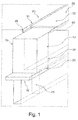
- Fig. 1 shows a joint seal 70 according to the invention arranged in a joint 30.
- the joint seal 70 has an underfill 20 in the form of a quadrangular flat profile seen in cross section, arranged on a joint bottom 32 of the joint 30.
- a bituminous first mass 34 is arranged, which extends over almost the entire height of the joint 30.
- this has a widening 38.
- a thin layer of a titanium dioxide-containing and bituminous second material 50 according to the invention is applied, which forms an exposed surface 52 of the joint seal 10 according to the invention.
- the joint 30 has two opposite joint flanks 34 and 36, which can be provided with a bonding agent before penetration of the first and second masses 10 and 50, respectively.
- the gap 30 has approximately a depth of 30 mm and a width of 15 mm, the broadening 38 a width of 18 mm.
- the joint 30 has a notch cut 40 which has a depth of about 25 mm and a width of about 5 mm. It is arranged approximately centrally on the joint bottom 32.
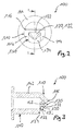
- Fig. 2 shows a nozzle according to the invention 100, by means of which preferably a first bitumen-containing mass or a second bitumen-containing and titanium dioxide-containing mass, but also other materials are austragbar.
- This nozzle 100 may advantageously be part of a discharge device (not shown), for example a caulking gun or a hand extruder.
- the nozzle 100 has a flange 144 and, opposite thereto, a nozzle head 110, which is approximately triangular in cross-section (see FIG Fig. 3 ), on.
- the nozzle head 110 has in its tip a smoothing edge 116 and a nozzle opening 120 with an opening edge 123, wherein through the nozzle opening 120, an opening area 122 (see Fig. 3 ) is defined.
- the nozzle head 110 has on one of its triangular surfaces a discharge part 130, which comprises the nozzle opening 120 except for the formation of a discharge opening 132.
- the discharge part 130 is formed in parts solid with the nozzle head 110. However, it may also be provided a non-massive training.
- contact surfaces 112 and 114 are formed in the triangular surface of the nozzle head 110, the attachment to a surface, for example, left and right of a joint, or a reason of expansion, as already described in the general description, adjacent one hand to a surface, for example, a traffic area, on the other hand to the joint, serve.
- Fig. 3 is a sectional view of the nozzle 100 according to Fig. 2 , from which particularly well the configuration of the nozzle opening 120 with the opening surface 122 and the discharge opening 132 with the discharge opening face 133 can be seen, which is spaced apart outwardly in relation to the opening surface 122 of the nozzle opening 120.
- the discharge part 130 is projectingly arranged on the triangular surface of the nozzle head 110.
- a circumferential groove 142 can be seen on a nozzle body 140, which is a locking or fixing of the nozzle 100, for example on a twin-screw extruder in the context of filling a discharge device which carries the nozzle 100 serves.
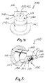
- Fig. 4 shows in a perspective view of the nozzle 100 according to Fig. 2 , as well as the Fig. 5 , in particular from Fig. 5 the projecting formation of the discharge part 130 is clearly visible.
- the discharge part 130 has an outer wall 134 and, subsequent thereto, a side wall 136 on each of three sides.
- the side walls 136 are formed with a return to the opening edge 122 of the nozzle opening 120.
- the discharge opening 132 itself is approximately triangular in shape with an open base edge or area on the opening edge 123 of the nozzle opening 120.
- the contact surfaces 112 and 114 serve, for example, a support on a surface 60 according to Fig. 1 or an overlay on the basis of a widening 38 according to Fig. 1 , In the latter case, then the width of the discharge part 130 in approximately the width of the joint 30 according to Fig. 1 correspond and dipping the discharge part 130 in this gap 30 when using the nozzle 100. Then, the joint 30 according to Fig. 1 be filled with at least one layer of a first mass 10. Subsequently, a nozzle 100 can be used with a discharge part 130 having a larger width, wherein then contact surfaces 112 and 114 with the surface 60 according to FIG Fig.
- the second mass 50 can be introduced into the expansion 38, wherein the discharge part 130 then dips into the expansion 38. If, for example, the first mass 10 is introduced into a joint 30 with a widening 38 with a nozzle 100, the second mass 50 can subsequently be introduced in strip form in the region of the widening 38 due to the smooth and closed filling of the joint 30. As far as a joint 30 no widening 38 according to Fig. 1 can, for example, a first mass 10 in at least one layer in the joint 30 according to Fig.
- a joint seal 70 can be generated (s. Fig. 1 ).
- An exemplary bitumen-containing first composition was prepared from 53 wt .-% of a bitumen with a needle penetration at 25 ° C according to DIN EN 1426 from about 160 / 0.1 mm to about 220 / 0.1 mm, 7 wt .-% of a styrene Isoprene-styrene / styrene-isoprene (block) copolymer, 6% by weight of a gum powder made from a recycled rubber product, in particular car tires having a grain size in a range of> 0 to about 0.5 mm, 1, 5% by weight of a montan wax having a solidification point ranging from about 130 ° C to about 150 ° C, 1% by weight of a grafted etylene-maleic anhydride copolymer in the form of pastilles, 12% by weight of a naphthenic process oil Plasticizer, 2% by weight of one fibrous modifier in the form of cellulosic fiber
- a titanium dioxide-containing and bituminous second mass was prepared from 40 wt .-% of a bitumen with a needle penetration at 25 ° C according to DIN EN 1426 from about 160 / 0.1 mm to about 220 / 0.1 mm, 5 wt .-% of a Styrene-isoprene-styrene / styrene-isoprene (block) copolymers, 4 wt .-% of a rubber powder, prepared from a recyclate of rubber products, in particular car tires with a grain size in a range of> 0 to about 0.5 mm, 1 wt % of a montan wax having a freezing point in a range from about 130 ° C to about 150 ° C, 0.7% by weight of a grafted etylene-maleic anhydride copolymer in the form of pastilles, 9% by weight of a naphthenic process oil as a plasticizer, 1.3% by weight of
- the first and second masses prepared as described above had a dynamic viscosity, measured in accordance with DIN EN 13702, at a temperature of 100 ° C., at a pore rate of 20 sec -1 of 75 Pa.s (first mass) or 110 Pa.s ( second mass), at a temperature of 110 ° C. of 45 Pa.s (first mass) or 67 Pa.s (second mass), at a temperature of 120 ° C. of 27 Pa.s (first mass) and 48 Pa, respectively.
- the first and second masses As described above, all the substances mentioned were mixed and stirred together at about 190 ° C. for 3 hours. Subsequently, they were molded to form bars or, particularly at the second mass, tapes and allowed to cool.
- the first and second mass in bar form can then be supplied in particular to a twin-screw extruder, so that on-site processing can be carried out as described in the general description.
- the twin-screw extruder via the twin-screw extruder, the first or second mass in a caulking gun or hand extruder, preferably with a nozzle as in Fig. 2 to 5 described, discharged and then the gap on the cartridge gun or the hand extruder, in particular a vertical joint in a concrete protective wall, are filled.
- a flat nozzle preferably according to the Fig. 2 to 5 , more preferably with a larger opening diameter to achieve coverage of the at least one layer of the first mass disposed therebelow, preferably in that the joint has a widening to the adjacent surface into which the second mass can then be introduced.
- an underfill can be inserted into it and the joint flanks can be provided with an adhesion promoter, as described above in the general description.
- a joint seal is provided which, in particular for vertical joints in concrete protective walls, has the highest possible service life, since corrosion and other types of leaks in concrete protective walls are well prevented.
Landscapes
- Engineering & Computer Science (AREA)
- Chemical & Material Sciences (AREA)
- Structural Engineering (AREA)
- Civil Engineering (AREA)
- Ceramic Engineering (AREA)
- Architecture (AREA)
- Materials Engineering (AREA)
- Organic Chemistry (AREA)
- Health & Medical Sciences (AREA)
- Chemical Kinetics & Catalysis (AREA)
- Medicinal Chemistry (AREA)
- Polymers & Plastics (AREA)
- Mining & Mineral Resources (AREA)
- Compositions Of Macromolecular Compounds (AREA)
- Road Paving Structures (AREA)
- Sealing Material Composition (AREA)
Priority Applications (1)
| Application Number | Priority Date | Filing Date | Title |
|---|---|---|---|
| PL16165251T PL3081615T3 (pl) | 2015-04-14 | 2016-04-14 | Szczeliwo do szczeliny obejmujące co najmniej jedną warstwę pierwszej masy zawierającej bitum i drugiej masy zawierającej bitum |
Applications Claiming Priority (1)
| Application Number | Priority Date | Filing Date | Title |
|---|---|---|---|
| DE102015105686.0A DE102015105686A1 (de) | 2015-04-14 | 2015-04-14 | Fugenabdichtung für eine Fuge mit mindestens einer Schicht einer bitumenhaltigen ersten und einer bitumenhaltigen zweiten Masse |
Publications (4)
| Publication Number | Publication Date |
|---|---|
| EP3081615A2 true EP3081615A2 (fr) | 2016-10-19 |
| EP3081615A3 EP3081615A3 (fr) | 2016-12-28 |
| EP3081615B1 EP3081615B1 (fr) | 2020-06-10 |
| EP3081615B9 EP3081615B9 (fr) | 2020-12-02 |
Family
ID=55910725
Family Applications (1)
| Application Number | Title | Priority Date | Filing Date |
|---|---|---|---|
| EP16165251.6A Active EP3081615B9 (fr) | 2015-04-14 | 2016-04-14 | Element d'etancheification pour un joint comprenant au moins une couche d'une premiere masse comprenant du bitume et d'une seconde masse comprenant du bitume |
Country Status (5)
| Country | Link |
|---|---|
| EP (1) | EP3081615B9 (fr) |
| DE (1) | DE102015105686A1 (fr) |
| ES (1) | ES2816751T3 (fr) |
| HU (1) | HUE050857T2 (fr) |
| PL (1) | PL3081615T3 (fr) |
Cited By (3)
| Publication number | Priority date | Publication date | Assignee | Title |
|---|---|---|---|---|
| WO2019145302A1 (fr) * | 2018-01-23 | 2019-08-01 | Ask Chemicals Gmbh | Composition, matériau de jointoiement et procédé pour réaliser un joint |
| CN113774772A (zh) * | 2020-12-24 | 2021-12-10 | 安徽丰林建设工程有限公司 | 一种道路修补保护设备 |
| WO2022035922A1 (fr) * | 2020-08-11 | 2022-02-17 | Asphalt Materials, Inc. | Procédés de scellement de fissures et de joints de dilatation |
Citations (3)
| Publication number | Priority date | Publication date | Assignee | Title |
|---|---|---|---|---|
| EP0646675B1 (fr) | 1993-10-01 | 1998-02-18 | DENSO-Holding GmbH & Co. | Procédé pour édifier des jointures à surfaces partielles de revêtements en asphalte et dispositif pour l'exécution du procédé |
| EP2557230A2 (fr) | 2011-08-02 | 2013-02-13 | DENSO-Holding GmbH & Co. | Bande de joint pour la construction de routes avec couche adhésive activable |
| WO2014173513A1 (fr) | 2013-04-22 | 2014-10-30 | Denso-Holding Gmbh & Co. | Masse pour le remplissage de joints et/ou de fissures |
Family Cites Families (11)
| Publication number | Priority date | Publication date | Assignee | Title |
|---|---|---|---|---|
| GB598696A (en) * | 1946-02-22 | 1948-02-24 | Claude Russell De Berry | Improvements in expansion jointing compositions |
| CH516718A (de) * | 1971-04-28 | 1971-12-15 | Imhof Meinrad | Düse für Kittpresse |
| US4490493A (en) * | 1983-12-16 | 1984-12-25 | Shell Oil Company | Stabilized bituminous blends |
| US5249876A (en) * | 1990-12-03 | 1993-10-05 | Hattman Harold M | Caulking nozzle |
| DE29719428U1 (de) * | 1997-11-03 | 1998-01-22 | Kühn, Manfred, 74632 Neuenstein | Spritzdüse für Kartusche |
| DE10212591B4 (de) * | 2002-03-15 | 2007-03-29 | Wilhelm Dipl.-Ing. Kämereit | Titandioxid enthaltende Beschichtung oder Beimischung für Kontaktflächen bei der Abgas- und Abwasserreinigung |
| ATE454425T1 (de) * | 2002-10-11 | 2010-01-15 | Shell Int Research | Bitumenzusammensetzung |
| DE102004029869B4 (de) * | 2004-06-16 | 2007-03-22 | BAM Bundesanstalt für Materialforschung und -prüfung | Straßenbelag |
| DE102004043111A1 (de) * | 2004-09-07 | 2006-03-09 | Henkel Kgaa | Düse für die Abgabe einer fließfähigen Substanz |
| WO2007093586A1 (fr) * | 2006-02-13 | 2007-08-23 | Total France | Mastic bitumineux comprenant des ultrafines et ses applications |
| CA2698507A1 (fr) * | 2010-03-31 | 2011-09-30 | 1616515 Alberta Ltd. | Composition d'asphalte reflechissante |
-
2015
- 2015-04-14 DE DE102015105686.0A patent/DE102015105686A1/de not_active Withdrawn
-
2016
- 2016-04-14 EP EP16165251.6A patent/EP3081615B9/fr active Active
- 2016-04-14 PL PL16165251T patent/PL3081615T3/pl unknown
- 2016-04-14 ES ES16165251T patent/ES2816751T3/es active Active
- 2016-04-14 HU HUE16165251A patent/HUE050857T2/hu unknown
Patent Citations (3)
| Publication number | Priority date | Publication date | Assignee | Title |
|---|---|---|---|---|
| EP0646675B1 (fr) | 1993-10-01 | 1998-02-18 | DENSO-Holding GmbH & Co. | Procédé pour édifier des jointures à surfaces partielles de revêtements en asphalte et dispositif pour l'exécution du procédé |
| EP2557230A2 (fr) | 2011-08-02 | 2013-02-13 | DENSO-Holding GmbH & Co. | Bande de joint pour la construction de routes avec couche adhésive activable |
| WO2014173513A1 (fr) | 2013-04-22 | 2014-10-30 | Denso-Holding Gmbh & Co. | Masse pour le remplissage de joints et/ou de fissures |
Cited By (3)
| Publication number | Priority date | Publication date | Assignee | Title |
|---|---|---|---|---|
| WO2019145302A1 (fr) * | 2018-01-23 | 2019-08-01 | Ask Chemicals Gmbh | Composition, matériau de jointoiement et procédé pour réaliser un joint |
| WO2022035922A1 (fr) * | 2020-08-11 | 2022-02-17 | Asphalt Materials, Inc. | Procédés de scellement de fissures et de joints de dilatation |
| CN113774772A (zh) * | 2020-12-24 | 2021-12-10 | 安徽丰林建设工程有限公司 | 一种道路修补保护设备 |
Also Published As
| Publication number | Publication date |
|---|---|
| DE102015105686A1 (de) | 2016-10-20 |
| EP3081615B9 (fr) | 2020-12-02 |
| ES2816751T3 (es) | 2021-04-05 |
| HUE050857T2 (hu) | 2021-01-28 |
| PL3081615T3 (pl) | 2021-01-11 |
| EP3081615B1 (fr) | 2020-06-10 |
| EP3081615A3 (fr) | 2016-12-28 |
Similar Documents
| Publication | Publication Date | Title |
|---|---|---|
| EP2859050B1 (fr) | Masse de jointoiement | |
| EP2557230B1 (fr) | Utilisation d'une bande de joint pour la construction de routes avec couche adhésive activable | |
| EP3081615B1 (fr) | Element d'etancheification pour un joint comprenant au moins une couche d'une premiere masse comprenant du bitume et d'une seconde masse comprenant du bitume | |
| DE2319603B2 (de) | Lösungsmittelfreie Schmelzmasse | |
| DE1769180A1 (de) | Wetterfestes Abdichtungsmaterial | |
| EP2873700B1 (fr) | Bande d'étanchéification et procédé de fabrication d'une telle bande d'étanchéification | |
| KR101386116B1 (ko) | 고부착 및 내후성 가열식 아스팔트계 실란트를 이용한 교량지하차도부 신축이음재 시공방법 | |
| DE202007011257U1 (de) | Fugenband für den Straßenbau | |
| DE29719780U1 (de) | Fugenabdeckband für asphaltierte Flächen und daraus hergestellte Fugenabdeckung | |
| EP2089210A1 (fr) | Procédé de fabrication d'un récipient à liquide médical en matière synthétique flexible, manchon en film servant de produit intermédiaire pour ce récipient médical et récipient médical fabriqué avec ce procédé | |
| KR101465103B1 (ko) | 내후성 가열식 아스팔트계 실란트를 이용한 지하차도부 신축이음재 시공구조 | |
| EP0182937A1 (fr) | Procédé de fabrication d'asphalte à couler à partir de béton asphaltique de recyclage et asphalte à couler ainsi fabriqué | |
| EP1983102B1 (fr) | Bande de joint en bitume plastique élastique pouvant fondre destinée à la fabrication de raccords et son procédé de fabrication | |
| KR101956874B1 (ko) | 소성변형 방지용 아스콘 조성물, 이의 제조방법 및 이를 사용한 시공방법 | |
| EP2088240B1 (fr) | Système et procédé de remplissage d'un joint entre un rail et une surface limitrophe | |
| EP2647763B1 (fr) | Bande de joint pour l'introduction de joints de raccordement ou de réparation dans la zone supérieure d'un revêtement de route | |
| EP0705999A1 (fr) | Dispositif pour l'étanchéité d'un joint dans une construction | |
| DE202008017283U1 (de) | Asphaltierte Verkehrsfläche | |
| DE102015003637A1 (de) | Fugenband zum Abdichten von Fugen | |
| DE102012222569B4 (de) | Verfahren zum Herstellen einer Asphaltdeckschicht und Asphaltdeckschicht hierfür | |
| DE102006016488A1 (de) | Verfahren zur Herstellung eines Bitumens, eines Teers oder eines Asphalts enthaltend Bambusfasern | |
| EP2755929B1 (fr) | Composition contenant des capsules | |
| WO2000015719A1 (fr) | Procede de production de recouvrements contenant de l'asphalte dans la construction routiere et industrielle | |
| DE202014101894U1 (de) | Fuge zum Ausgleichen von mechanischen Spannungen | |
| EP2540911A2 (fr) | Bande de joint pour la construction de routes |
Legal Events
| Date | Code | Title | Description |
|---|---|---|---|
| PUAI | Public reference made under article 153(3) epc to a published international application that has entered the european phase |
Free format text: ORIGINAL CODE: 0009012 |
|
| AK | Designated contracting states |
Kind code of ref document: A2 Designated state(s): AL AT BE BG CH CY CZ DE DK EE ES FI FR GB GR HR HU IE IS IT LI LT LU LV MC MK MT NL NO PL PT RO RS SE SI SK SM TR |
|
| AX | Request for extension of the european patent |
Extension state: BA ME |
|
| PUAL | Search report despatched |
Free format text: ORIGINAL CODE: 0009013 |
|
| AK | Designated contracting states |
Kind code of ref document: A3 Designated state(s): AL AT BE BG CH CY CZ DE DK EE ES FI FR GB GR HR HU IE IS IT LI LT LU LV MC MK MT NL NO PL PT RO RS SE SI SK SM TR |
|
| AX | Request for extension of the european patent |
Extension state: BA ME |
|
| RIC1 | Information provided on ipc code assigned before grant |
Ipc: C04B 20/10 20060101ALI20161121BHEP Ipc: E02D 31/00 20060101ALI20161121BHEP Ipc: C09K 3/18 20060101AFI20161121BHEP Ipc: C08L 95/00 20060101ALI20161121BHEP Ipc: C08K 3/22 20060101ALI20161121BHEP Ipc: B05B 1/00 20060101ALI20161121BHEP Ipc: C09K 3/10 20060101ALI20161121BHEP Ipc: C09K 3/12 20060101ALI20161121BHEP Ipc: E01C 23/09 20060101ALI20161121BHEP Ipc: B65D 25/40 20060101ALI20161121BHEP |
|
| STAA | Information on the status of an ep patent application or granted ep patent |
Free format text: STATUS: REQUEST FOR EXAMINATION WAS MADE |
|
| 17P | Request for examination filed |
Effective date: 20170626 |
|
| RBV | Designated contracting states (corrected) |
Designated state(s): AL AT BE BG CH CY CZ DE DK EE ES FI FR GB GR HR HU IE IS IT LI LT LU LV MC MK MT NL NO PL PT RO RS SE SI SK SM TR |
|
| STAA | Information on the status of an ep patent application or granted ep patent |
Free format text: STATUS: EXAMINATION IS IN PROGRESS |
|
| 17Q | First examination report despatched |
Effective date: 20181129 |
|
| RIC1 | Information provided on ipc code assigned before grant |
Ipc: C09K 3/18 20060101AFI20191210BHEP Ipc: C09K 3/10 20060101ALI20191210BHEP Ipc: C04B 26/26 20060101ALI20191210BHEP Ipc: E02D 31/00 20060101ALI20191210BHEP Ipc: E01C 23/09 20060101ALI20191210BHEP Ipc: C09K 3/12 20060101ALI20191210BHEP Ipc: C04B 20/10 20060101ALI20191210BHEP Ipc: B65D 25/40 20060101ALI20191210BHEP Ipc: C08L 95/00 20060101ALI20191210BHEP Ipc: C04B 111/00 20060101ALI20191210BHEP Ipc: B05B 1/00 20060101ALI20191210BHEP Ipc: C08K 3/22 20060101ALI20191210BHEP Ipc: C04B 111/72 20060101ALI20191210BHEP Ipc: E01C 11/10 20060101ALI20191210BHEP |
|
| GRAP | Despatch of communication of intention to grant a patent |
Free format text: ORIGINAL CODE: EPIDOSNIGR1 |
|
| STAA | Information on the status of an ep patent application or granted ep patent |
Free format text: STATUS: GRANT OF PATENT IS INTENDED |
|
| INTG | Intention to grant announced |
Effective date: 20200128 |
|
| GRAS | Grant fee paid |
Free format text: ORIGINAL CODE: EPIDOSNIGR3 |
|
| GRAA | (expected) grant |
Free format text: ORIGINAL CODE: 0009210 |
|
| STAA | Information on the status of an ep patent application or granted ep patent |
Free format text: STATUS: THE PATENT HAS BEEN GRANTED |
|
| AK | Designated contracting states |
Kind code of ref document: B1 Designated state(s): AL AT BE BG CH CY CZ DE DK EE ES FI FR GB GR HR HU IE IS IT LI LT LU LV MC MK MT NL NO PL PT RO RS SE SI SK SM TR |
|
| REG | Reference to a national code |
Ref country code: GB Ref legal event code: FG4D Free format text: NOT ENGLISH |
|
| REG | Reference to a national code |
Ref country code: CH Ref legal event code: EP Ref country code: AT Ref legal event code: REF Ref document number: 1279186 Country of ref document: AT Kind code of ref document: T Effective date: 20200615 |
|
| REG | Reference to a national code |
Ref country code: DE Ref legal event code: R096 Ref document number: 502016010167 Country of ref document: DE |
|
| REG | Reference to a national code |
Ref country code: IE Ref legal event code: FG4D Free format text: LANGUAGE OF EP DOCUMENT: GERMAN |
|
| REG | Reference to a national code |
Ref country code: CH Ref legal event code: NV Representative=s name: WEINMANN ZIMMERLI, CH |
|
| REG | Reference to a national code |
Ref country code: NL Ref legal event code: FP |
|
| REG | Reference to a national code |
Ref country code: LT Ref legal event code: MG4D |
|
| PG25 | Lapsed in a contracting state [announced via postgrant information from national office to epo] |
Ref country code: LT Free format text: LAPSE BECAUSE OF FAILURE TO SUBMIT A TRANSLATION OF THE DESCRIPTION OR TO PAY THE FEE WITHIN THE PRESCRIBED TIME-LIMIT Effective date: 20200610 Ref country code: SE Free format text: LAPSE BECAUSE OF FAILURE TO SUBMIT A TRANSLATION OF THE DESCRIPTION OR TO PAY THE FEE WITHIN THE PRESCRIBED TIME-LIMIT Effective date: 20200610 Ref country code: NO Free format text: LAPSE BECAUSE OF FAILURE TO SUBMIT A TRANSLATION OF THE DESCRIPTION OR TO PAY THE FEE WITHIN THE PRESCRIBED TIME-LIMIT Effective date: 20200910 Ref country code: FI Free format text: LAPSE BECAUSE OF FAILURE TO SUBMIT A TRANSLATION OF THE DESCRIPTION OR TO PAY THE FEE WITHIN THE PRESCRIBED TIME-LIMIT Effective date: 20200610 |
|
| REG | Reference to a national code |
Ref country code: CH Ref legal event code: PK Free format text: BERICHTIGUNG B9 |
|
| PG25 | Lapsed in a contracting state [announced via postgrant information from national office to epo] |
Ref country code: HR Free format text: LAPSE BECAUSE OF FAILURE TO SUBMIT A TRANSLATION OF THE DESCRIPTION OR TO PAY THE FEE WITHIN THE PRESCRIBED TIME-LIMIT Effective date: 20200610 Ref country code: RS Free format text: LAPSE BECAUSE OF FAILURE TO SUBMIT A TRANSLATION OF THE DESCRIPTION OR TO PAY THE FEE WITHIN THE PRESCRIBED TIME-LIMIT Effective date: 20200610 Ref country code: BG Free format text: LAPSE BECAUSE OF FAILURE TO SUBMIT A TRANSLATION OF THE DESCRIPTION OR TO PAY THE FEE WITHIN THE PRESCRIBED TIME-LIMIT Effective date: 20200910 Ref country code: LV Free format text: LAPSE BECAUSE OF FAILURE TO SUBMIT A TRANSLATION OF THE DESCRIPTION OR TO PAY THE FEE WITHIN THE PRESCRIBED TIME-LIMIT Effective date: 20200610 |
|
| PG25 | Lapsed in a contracting state [announced via postgrant information from national office to epo] |
Ref country code: AL Free format text: LAPSE BECAUSE OF FAILURE TO SUBMIT A TRANSLATION OF THE DESCRIPTION OR TO PAY THE FEE WITHIN THE PRESCRIBED TIME-LIMIT Effective date: 20200610 |
|
| REG | Reference to a national code |
Ref country code: HU Ref legal event code: AG4A Ref document number: E050857 Country of ref document: HU |
|
| PG25 | Lapsed in a contracting state [announced via postgrant information from national office to epo] |
Ref country code: SM Free format text: LAPSE BECAUSE OF FAILURE TO SUBMIT A TRANSLATION OF THE DESCRIPTION OR TO PAY THE FEE WITHIN THE PRESCRIBED TIME-LIMIT Effective date: 20200610 Ref country code: EE Free format text: LAPSE BECAUSE OF FAILURE TO SUBMIT A TRANSLATION OF THE DESCRIPTION OR TO PAY THE FEE WITHIN THE PRESCRIBED TIME-LIMIT Effective date: 20200610 Ref country code: RO Free format text: LAPSE BECAUSE OF FAILURE TO SUBMIT A TRANSLATION OF THE DESCRIPTION OR TO PAY THE FEE WITHIN THE PRESCRIBED TIME-LIMIT Effective date: 20200610 Ref country code: PT Free format text: LAPSE BECAUSE OF FAILURE TO SUBMIT A TRANSLATION OF THE DESCRIPTION OR TO PAY THE FEE WITHIN THE PRESCRIBED TIME-LIMIT Effective date: 20201012 |
|
| PG25 | Lapsed in a contracting state [announced via postgrant information from national office to epo] |
Ref country code: SK Free format text: LAPSE BECAUSE OF FAILURE TO SUBMIT A TRANSLATION OF THE DESCRIPTION OR TO PAY THE FEE WITHIN THE PRESCRIBED TIME-LIMIT Effective date: 20200610 Ref country code: IS Free format text: LAPSE BECAUSE OF FAILURE TO SUBMIT A TRANSLATION OF THE DESCRIPTION OR TO PAY THE FEE WITHIN THE PRESCRIBED TIME-LIMIT Effective date: 20201010 |
|
| REG | Reference to a national code |
Ref country code: DE Ref legal event code: R097 Ref document number: 502016010167 Country of ref document: DE |
|
| REG | Reference to a national code |
Ref country code: ES Ref legal event code: FG2A Ref document number: 2816751 Country of ref document: ES Kind code of ref document: T3 Effective date: 20210405 |
|
| PLBE | No opposition filed within time limit |
Free format text: ORIGINAL CODE: 0009261 |
|
| STAA | Information on the status of an ep patent application or granted ep patent |
Free format text: STATUS: NO OPPOSITION FILED WITHIN TIME LIMIT |
|
| PG25 | Lapsed in a contracting state [announced via postgrant information from national office to epo] |
Ref country code: DK Free format text: LAPSE BECAUSE OF FAILURE TO SUBMIT A TRANSLATION OF THE DESCRIPTION OR TO PAY THE FEE WITHIN THE PRESCRIBED TIME-LIMIT Effective date: 20200610 |
|
| 26N | No opposition filed |
Effective date: 20210311 |
|
| PG25 | Lapsed in a contracting state [announced via postgrant information from national office to epo] |
Ref country code: SI Free format text: LAPSE BECAUSE OF FAILURE TO SUBMIT A TRANSLATION OF THE DESCRIPTION OR TO PAY THE FEE WITHIN THE PRESCRIBED TIME-LIMIT Effective date: 20200610 |
|
| PGFP | Annual fee paid to national office [announced via postgrant information from national office to epo] |
Ref country code: IT Payment date: 20210430 Year of fee payment: 6 Ref country code: CZ Payment date: 20210505 Year of fee payment: 6 |
|
| PGFP | Annual fee paid to national office [announced via postgrant information from national office to epo] |
Ref country code: ES Payment date: 20210519 Year of fee payment: 6 Ref country code: TR Payment date: 20210505 Year of fee payment: 6 Ref country code: HU Payment date: 20210511 Year of fee payment: 6 Ref country code: GB Payment date: 20210422 Year of fee payment: 6 |
|
| PG25 | Lapsed in a contracting state [announced via postgrant information from national office to epo] |
Ref country code: MC Free format text: LAPSE BECAUSE OF FAILURE TO SUBMIT A TRANSLATION OF THE DESCRIPTION OR TO PAY THE FEE WITHIN THE PRESCRIBED TIME-LIMIT Effective date: 20200610 |
|
| PG25 | Lapsed in a contracting state [announced via postgrant information from national office to epo] |
Ref country code: LU Free format text: LAPSE BECAUSE OF NON-PAYMENT OF DUE FEES Effective date: 20210414 |
|
| PG25 | Lapsed in a contracting state [announced via postgrant information from national office to epo] |
Ref country code: IE Free format text: LAPSE BECAUSE OF NON-PAYMENT OF DUE FEES Effective date: 20210414 |
|
| PG25 | Lapsed in a contracting state [announced via postgrant information from national office to epo] |
Ref country code: IS Free format text: LAPSE BECAUSE OF FAILURE TO SUBMIT A TRANSLATION OF THE DESCRIPTION OR TO PAY THE FEE WITHIN THE PRESCRIBED TIME-LIMIT Effective date: 20201010 |
|
| GBPC | Gb: european patent ceased through non-payment of renewal fee |
Effective date: 20220414 |
|
| PG25 | Lapsed in a contracting state [announced via postgrant information from national office to epo] |
Ref country code: HU Free format text: LAPSE BECAUSE OF NON-PAYMENT OF DUE FEES Effective date: 20220415 Ref country code: GB Free format text: LAPSE BECAUSE OF NON-PAYMENT OF DUE FEES Effective date: 20220414 Ref country code: CZ Free format text: LAPSE BECAUSE OF NON-PAYMENT OF DUE FEES Effective date: 20220414 |
|
| REG | Reference to a national code |
Ref country code: ES Ref legal event code: FD2A Effective date: 20230529 |
|
| PG25 | Lapsed in a contracting state [announced via postgrant information from national office to epo] |
Ref country code: IT Free format text: LAPSE BECAUSE OF NON-PAYMENT OF DUE FEES Effective date: 20220414 |
|
| PG25 | Lapsed in a contracting state [announced via postgrant information from national office to epo] |
Ref country code: CY Free format text: LAPSE BECAUSE OF FAILURE TO SUBMIT A TRANSLATION OF THE DESCRIPTION OR TO PAY THE FEE WITHIN THE PRESCRIBED TIME-LIMIT Effective date: 20200610 |
|
| P01 | Opt-out of the competence of the unified patent court (upc) registered |
Effective date: 20230528 |
|
| PG25 | Lapsed in a contracting state [announced via postgrant information from national office to epo] |
Ref country code: GR Free format text: LAPSE BECAUSE OF FAILURE TO SUBMIT A TRANSLATION OF THE DESCRIPTION OR TO PAY THE FEE WITHIN THE PRESCRIBED TIME-LIMIT Effective date: 20200610 Ref country code: ES Free format text: LAPSE BECAUSE OF NON-PAYMENT OF DUE FEES Effective date: 20220415 |
|
| PG25 | Lapsed in a contracting state [announced via postgrant information from national office to epo] |
Ref country code: MK Free format text: LAPSE BECAUSE OF FAILURE TO SUBMIT A TRANSLATION OF THE DESCRIPTION OR TO PAY THE FEE WITHIN THE PRESCRIBED TIME-LIMIT Effective date: 20200610 |
|
| PG25 | Lapsed in a contracting state [announced via postgrant information from national office to epo] |
Ref country code: TR Free format text: LAPSE BECAUSE OF NON-PAYMENT OF DUE FEES Effective date: 20220414 Ref country code: MT Free format text: LAPSE BECAUSE OF FAILURE TO SUBMIT A TRANSLATION OF THE DESCRIPTION OR TO PAY THE FEE WITHIN THE PRESCRIBED TIME-LIMIT Effective date: 20200610 |
|
| REG | Reference to a national code |
Ref country code: CH Ref legal event code: U11 Free format text: ST27 STATUS EVENT CODE: U-0-0-U10-U11 (AS PROVIDED BY THE NATIONAL OFFICE) Effective date: 20260501 |
|
| PGFP | Annual fee paid to national office [announced via postgrant information from national office to epo] |
Ref country code: NL Payment date: 20260422 Year of fee payment: 11 |
|
| PGFP | Annual fee paid to national office [announced via postgrant information from national office to epo] |
Ref country code: PL Payment date: 20260413 Year of fee payment: 11 |
|
| PGFP | Annual fee paid to national office [announced via postgrant information from national office to epo] |
Ref country code: DE Payment date: 20260428 Year of fee payment: 11 |
|
| PGFP | Annual fee paid to national office [announced via postgrant information from national office to epo] |
Ref country code: AT Payment date: 20260420 Year of fee payment: 11 |
|
| PGFP | Annual fee paid to national office [announced via postgrant information from national office to epo] |
Ref country code: CH Payment date: 20260501 Year of fee payment: 11 Ref country code: BE Payment date: 20260422 Year of fee payment: 11 |
|
| PGFP | Annual fee paid to national office [announced via postgrant information from national office to epo] |
Ref country code: FR Payment date: 20260422 Year of fee payment: 11 |