EP3081700B1 - Rüttelvorrichtung - Google Patents
Rüttelvorrichtung Download PDFInfo
- Publication number
- EP3081700B1 EP3081700B1 EP16164194.9A EP16164194A EP3081700B1 EP 3081700 B1 EP3081700 B1 EP 3081700B1 EP 16164194 A EP16164194 A EP 16164194A EP 3081700 B1 EP3081700 B1 EP 3081700B1
- Authority
- EP
- European Patent Office
- Prior art keywords
- pump
- lubricant
- circuit
- vibrating apparatus
- oil
- Prior art date
- Legal status (The legal status is an assumption and is not a legal conclusion. Google has not performed a legal analysis and makes no representation as to the accuracy of the status listed.)
- Active
Links
Images
Classifications
-
- E—FIXED CONSTRUCTIONS
- E02—HYDRAULIC ENGINEERING; FOUNDATIONS; SOIL SHIFTING
- E02D—FOUNDATIONS; EXCAVATIONS; EMBANKMENTS; UNDERGROUND OR UNDERWATER STRUCTURES
- E02D7/00—Methods or apparatus for placing sheet pile bulkheads, piles, mouldpipes, or other moulds
- E02D7/18—Placing by vibrating
Definitions
- the present invention relates to a vibrator device for attachment to a construction machine or a carrier.
- the vibrator is often referred to as a vibrator.
- the vibrator typically serves to introduce an article into the ground.
- a construction device or a carrier device is typically provided with a broker on which a vibrating device is arranged to be movable vertically to the ground.
- a connecting device for holding the objects to be driven into the ground.
- the connecting device serves for transmitting the vibrating movement generated by the vibrating device to the object to be driven into the ground.
- the prior art provides FR2529292A1 To grow a gear oil pump directly on the excitation cell of the vibrator, wherein the pump is driven by a shaft of the vibrator.
- a transmission oil circuit between the vibrator and the jig carrying the construction equipment which is also referred to as a carrier device, or provided between the vibrator and a so-called "power pack".
- a power pack is a unit separate from the vibrator, which can supply all lines and connections for operating the vibrator device.
- the power pack is arranged on the ground, but can also be attached to a construction equipment. However, the power pack can not be moved together with the jogger at the broker.
- the transmission oil is then pumped back and forth between the construction equipment or the power pack via a hose connection, with hose lengths of up to 80 meters possibly having to be overcome.
- the oil change is quite complex, since not only the transmission cell but also the hoses and the cooling device on the construction machine or power pack must be emptied.
- On the construction machine or the power pack is a cooler with which the heated in the vibrator gear oil is cooled.
- the radiator is a conventional oil-air cooler. Since the pump is arranged on a shaft of the vibrator, circulation of the transmission oil takes place only during operation of the vibrator.
- the invention is based on the object of specifying a device which advantageously further develops the generic vibrator device described above, inter alia with regard to an improvement in its service life and a reduction in the very high degree of wear.
- the shaker device for attachment to a construction equipment, in particular to a leader of a construction equipment, an exciter cell for generating a shaking movement, a connection for an oil drain of the excitation cell, a connection for an oil supply of the exciter cell, and a pump for conveying lubricant between the terminal for a lubricant drain and the connection for a lubricant supply.
- the vibrating device is characterized in that the pump via a separate line, preferably a pressure line, can be driven.
- a vibrating device or a vibrator is an attachable to a construction equipment or a carrier device working equipment.
- the excitation cell of the vibrator or vibrator describes the unit that generates the shaking motion.
- This is provided with a connection for a lubricant outlet and a connection for a lubricant supply.
- the vibrator device comprises a pump which is adapted to convey lubricant between the connection for a lubricant outlet and the connection for a lubricant supply of the exciter cell.
- the pump can be operated via a separate line, preferably a pressure line.
- As a pump all known in the art pump types can be used.
- the pump is for driving a lubricant circuit passing through the exciter cell, the lubricant drain port, the pump, and the lubricant supply port.
- the pump is arranged and / or attached to the draw yoke of the vibrator.
- the pump is not directly exposed to the vibrations of the excitation cell and thus significantly increases the life of the pump.
- the draw yoke is a portion of the shaker device for attachment to a construction equipment, in particular to a leader of a construction equipment. At the Ziehjoch the vibrator is moved vertically to the ground level.
- the vibrating device further comprises a heat exchanger, in particular a plate exchanger, for regulating the temperature of the lubricant to be pumped by the pump.
- the pump is for driving a lubricant circuit passing through the exciter cell, the lubricant drain port, the pump, the heat exchanger, and the lubricant supply port. It is irrelevant in which order the aforementioned components are arranged in the lubricant circuit.
- the heat exchanger has a first circuit for flowing through the pump to be conveyed lubricant and a second circuit which is adapted to regulate the temperature of the first circuit in its temperature with a temperature regulating medium.
- a temperature control medium is in particular a lubricant or a hydraulic lubricant in question.
- another suitable fluid flows through the second circuit of the heat exchanger.
- the second circuit of the heat exchanger supply connections for a supply and a drainage of a Temperaturreguliermediums are arranged on the vibrator.
- the heat exchanger and the pump independent of the operation of the vibrator, it is possible to perform cooling between the on-times of the vibrator and thus to rapidly reduce a temperature of the vibrator reached during a working operation. Also, a total of longer operating times are achievable before overheating of the vibrator threatens.
- the lubricant circuit through the excitation cell is no longer coupled to the operation of the excitation cell. Cooling of the lubricant used in the excitation cell can therefore be accelerated even during breaks by passing through the heat exchanger.
- the lubricant for the excitation cell is exclusively in the vibrator and not - as in the prior art - a large proportion in the construction equipment or power pack. Also, the amount of lubricant in the connecting tubes between vibrator and the construction equipment or the power pack is no longer necessary. Mixing of lubricant of different quality or state when replacing the attachment to various construction machines or power packs are excluded because the lubricant circuit is not connected to an external device. Thus, it is also excluded that when changing the lubricant, the new lubricant contaminated by old, contaminated lubricant from various construction machinery or power packs and thus deteriorated in its properties (not all lubricants are miscible with each other!).
- the cooling of the lubricant circuit is made by the heat exchanger directly to the vibrator, also eliminates the need to cool the lubricant circuit on the construction equipment.
- the hose guides for guiding the lubricant from the vibrator device to the construction equipment and back as well as the corresponding hose deflections can be dispensed with.
- the second circuit of the heat exchanger is supplied with a temperature regulating medium, in particular a lubricant or a hydraulic lubricant, from a unit separate from the vibrating device.
- a temperature regulating medium in particular a lubricant or a hydraulic lubricant
- the second circuit of the heat exchanger is coupled to a temperature-regulating medium of the power pack or a construction device carrying the vibrator device.
- the separate unit that supplies the second circuit of the heat exchanger with the temperature regulating medium is the construction equipment or the carrier device to which the vibrator device can be attached.
- the separate unit is the power pack.
- the invention further comprises a construction device with a vibrating device, which comprises one of the feature combinations listed above.
- the invention comprises a construction device with a vibrating device, which contains a heat exchanger, wherein the second circuit of the heat exchanger with a temperature regulating medium, in particular a hydraulic lubricant, the construction equipment is supplied.
- the pump of the vibrator is driven by the control pressure of the construction equipment.
- the pump then sucks in the lubricant from the excitation cell and returns it through a heat exchanger back to the excitation cell, where all bearings and lubrication points are supplied with lubricant via holes.
- the second circuit of the heat exchanger is supplied with a temperature regulating medium, such as hydraulic lubricant, from the carrier.
- the lubricant and subsequently also the exciter cell is then adapted to the temperature of the temperature regulating medium of the carrier device.
- the vibrator device flows with a heated Temperaturreguliermedium in the second circuit of the heat exchanger and through this its heat to the lubricant circuit, which is operated by the pump in the vibrator.
- the excitation cell or the entire vibrator is heated, whereby a particularly harmful starting the vibrator can be avoided in a cold state.
- the vibrating device 1 an excitation cell 2 and arranged on the excitation cell 2 terminals 3, 4 for a lubricant outlet or a lubricant supply. From the connection 3 for a lubricant outlet, a line to the pump 5, which is responsible for a circulation or circulation of the lubricant circuit extends.
- the lubricant circuit continues to a heat exchanger 7, which is connected to a connection 4 for a lubricant supply to the exciter cell 2.
- the heat exchanger 7 comprises a second circuit which is suitable for influencing the temperature of the lubricant circuit which flows through the pump 5 and the excitation cell 2.
- the second circuit is fed by the supply ports 8 from a unit external to the shaker device and is preferably coupled to the gear lubricant circuit of the equipment or power pack.
- the transmission lubricant circuit preferably corresponds to that of the construction equipment to which the vibrator device is attached.
- the supply connections 8 can also be connected to a transmission lubricant circuit of a power pack.
- the drawing yoke of the vibrator 1 is characterized, which has an engagement portion with the construction equipment or with a leader of the Represents construction equipment.
- the pump 5 is arranged on the draw yoke 6.
- the pump 5 for circulating the lubricant circuit of the vibrator 1 can be driven via a separate line 9. This can ensure that a circulation of the lubricant circuit in the vibrator 1 is independent of their operation feasible.
- the separate conduit 9 is connected to the control pressure of the construction equipment or power pack.
Landscapes
- Engineering & Computer Science (AREA)
- Life Sciences & Earth Sciences (AREA)
- General Life Sciences & Earth Sciences (AREA)
- Mining & Mineral Resources (AREA)
- Paleontology (AREA)
- Civil Engineering (AREA)
- General Engineering & Computer Science (AREA)
- Structural Engineering (AREA)
- Apparatuses For Generation Of Mechanical Vibrations (AREA)
Description
- Die vorliegende Erfindung betrifft eine Rüttelvorrichtung zum Anbringen an einer Baumaschine oder ein Trägergerät. Die Rüttelvorrichtung wird oftmals auch als Rüttler bezeichnet.
- Die Rüttelvorrichtung dient typischerweise zum Einbringen eines Gegenstands in den Boden. Beispielsweise ist es damit möglich sogenannte Spundbohlen, Spundwände oder Pfähle durch Ausführen einer Rüttelbewegung in das Erdreich einzubringen.
- Beim Einbringen dieser Gegenstände in das Erdreich ist typischerweise ein Baugerät oder ein Trägergerät mit einem Mäkler versehen, an dem eine Rüttelvorrichtung vertikal zum Boden verfahrbar angeordnet ist. An der der Bodenfläche zugewandten Unterseite der Rüttelvorrichtung befindet sich üblicherweise eine Verbindungseinrichtung zum Halten der in das Erdreich einzutreibenden Gegenstände. Ferner dient die Verbindungseinrichtung zum Übertragen der von der Rüttelvorrichtung erzeugten Rüttelbewegung auf den in das Erdreich einzutreibenden Gegenstand.
- Herkömmliche Rüttler weisen einen sehr hohen Verschleiß auf, was in Folge auch dazu führt, dass sehr hohe Wartungskosten anfallen und mit einem frühen Ausfall des Rüttlers gerechnet werden muss.
- Um ein Überhitzen der Rüttelvorrichtung zu verhindern, sieht der Stand der Technik
FR2529292A1 - Der Erfindung liegt nun die Aufgabe zugrunde, eine Vorrichtung anzugeben, die die eingangs beschriebene gattungsgemäße Rüttelvorrichtung unter anderem hinsichtlich einer Verbesserung ihrer Standzeit und einer Verminderung des sehr hohen Verschleißes vorteilhaft weiterbildet.
- Die Lösung dieser Aufgabe erfolgt mit einer Rüttelvorrichtung, die die Merkmale des Anspruchs 1 umfasst.
- Demnach weist die Rüttelvorrichtung zum Anbringen an ein Baugerät, insbesondere an einen Mäkler eines Baugeräts, eine Erregerzelle zum Erzeugen einer Rüttelbewegung, einen Anschluss für einen Ölablauf der Erregerzelle, einen Anschluss für eine Ölzufuhr der Erregerzelle, und eine Pumpe zum Fördern von Schmiermittel zwischen dem Anschluss für einen Schmiermittelablauf und dem Anschluss für eine Schmiermittelzufuhr auf. Ferner ist die Rüttelvorrichtung dadurch gekennzeichnet, dass die Pumpe über eine separate Leitung, vorzugsweise eine Druckleitung, antreibbar ist.
- Eine Rüttelvorrichtung oder auch ein Rüttler ist ein an ein Baugerät oder ein Trägergerät anbringbares Arbeitsgerät. Die Erregerzelle der Rüttelvorrichtung oder des Rüttlers beschreibt dabei die Einheit, die die Rüttelbewegung erzeugt. Diese ist mit einem Anschluss für einen Schmiermittelablauf und einem Anschluss für eine Schmiermittelzufuhr versehen. Darüber hinaus umfasst die Rüttelvorrichtung eine Pumpe, die dazu ausgelegt ist, Schmiermittel zwischen dem Anschluss für einen Schmiermittelablauf und dem Anschluss für eine Schmiermittelzufuhr der Erregerzelle zu fördern. Dabei kann die Pumpe über eine separate Leitung, vorzugsweise eine Druckleitung, betrieben werden. Als Pumpe sind sämtliche im Stand der Technik bekannten Pumpentypen verwendbar.
- Durch das Vorsehen einer separaten Leitung zum Antreiben der Pumpe ist es im Gegensatz zum Stand der Technik möglich, einen Schmiermittelkreislauf durch die Erregerzelle unabhängig vom Betrieb der Rüttelvorrichtung bzw. der Erregerzelle zirkulieren zu lassen. Dadurch ist es möglich, die Rüttelvorrichtung vorzuwärmen und den besonders verschleißintensiven Zustand eines Kaltstarts zu umgehen.
- Vorzugsweise dient die Pumpe zum Antreiben eines Schmiermittelkreislaufs, der durch die Erregerzelle, den Anschluss für einen Schmiermittelablauf, die Pumpe und den Anschluss für eine Schmiermittelzufuhr verläuft.
- Dabei kann es zudem von Vorteil sein, wenn die Pumpe an dem Ziehjoch der Rüttelvorrichtung angeordnet und/oder befestigt ist. Dadurch ist die Pumpe nicht direkt den Vibrationen der Erregerzelle ausgesetzt und damit erhöht sich die Lebensdauer der Pumpe deutlich. Dadurch kann auch eine besonders platzsparende Anordnung der Pumpe verwirklicht werden. Das Ziehjoch ist ein Abschnitt der Rüttelvorrichtung zum Befestigen an einem Baugerät, insbesondere an einen Mäkler eines Baugeräts. An dem Ziehjoch wird die Rüttelvorrichtung vertikal zur Bodenebene verfahren.
- Nach einem weiteren optionalen, vorteilhaften Merkmal der vorliegenden Erfindung umfasst die Rüttelvorrichtung ferner einen Wärmetauscher, insbesondere einen Plattentauscher, zum Regulieren der Temperatur des durch die Pumpe förderbaren Schmiermittels. Vorzugsweise dient die Pumpe zum Antreiben eines Schmiermittelkreislaufs, der durch die Erregerzelle, den Anschluss für einen Schmiermittelablauf, die Pumpe, den Wärmetauscher und den Anschluss für eine Schmiermittelzufuhr verläuft. Dabei ist unerheblich, in welcher Reihenfolge die vorstehend genannten Bauteile in dem Schmiermittelkreislauf angeordnet sind.
- Vorzugsweise weist der Wärmetauscher einen ersten Kreislauf zum Durchströmen von durch die Pumpe zu fördernden Schmiermittel auf sowie einen zweiten Kreislauf, der dazu ausgelegt ist, mit einem Temperaturreguliermedium den ersten Kreislauf in seiner Temperatur zu regulieren. Als Temperaturreguliermedium kommt insbesondere ein Schmiermittel oder ein Hydraulikschmiermittel infrage. Es ist jedoch auch vorstellbar, dass ein anderes geeignetes Fluid durch den zweiten Kreislauf des Wärmetauschers strömt.
- Nach einer weiteren vorteilhaften Ausgestaltung der Erfindung weist der zweite Kreislauf des Wärmetauschers Versorgungsanschlüsse für ein Zu- und ein Ablaufen eines Temperaturreguliermediums auf. Dabei ist von Vorteil, wenn die Versorgungsanschlüsse für ein Zu- und ein Ablaufen an der Rüttelvorrichtung angeordnet sind.
- Dadurch ist es möglich eine Vielzahl von Vorteilen gegenüber den herkömmlichen Rüttelvorrichtungen im Stand der Technik zu erreichen.
- Durch Vorsehen des Wärmetauschers und der von dem Betrieb der Rüttelvorrichtung unabhängigen Pumpe ist es möglich, eine Kühlung zwischen den Einschaltzeiten der Rüttelvorrichtung vorzunehmen und somit eine während eines Arbeitsbetriebs erreichte Temperatur der Rüttelvorrichtung zügig zu senken. Auch sind insgesamt längere Einsatzzeiten erreichbar bevor eine Überhitzung der Rüttelvorrichtung droht. Der Schmiermittelkreislauf durch die Erregerzelle ist nicht länger an den Betrieb der Erregerzelle gekoppelt. Ein Abkühlen des in der Erregerzelle verwendeten Schmiermittels kann daher auch in Betriebspausen durch ein Durchleiten durch den Wärmetauscher beschleunigt werden.
- Zudem befindet sich das Schmiermittel für die Erregerzelle ausschließlich in der Rüttelvorrichtung und nicht - wie im Stand der Technik - zu einem großen Anteil im Baugerät oder Power-Pack. Auch ist die Menge des Schmiermittels in den Verbindungsschläuchen zwischen Rüttelvorrichtung und dem Baugerät oder dem Power-Pack nicht mehr notwendig. Vermischungen von Schmiermittel unterschiedlicher Qualität bzw. Zustand bei einem Tausch des Anbaugeräts an verschiedene Baumaschinen bzw. Power-Packs sind ausgeschlossen, da dessen Schmiermittelkreislauf nicht mit einem externen Gerät verbunden wird. Damit ist es auch ausgeschlossen, dass bei einem Wechsel des Schmiermittels, das neuwertige Schmiermittel durch altes, verunreinigtes Schmiermittel aus diversen Baumaschinen bzw. Power-Packs verunreinigt und damit in seinen Eigenschaften verschlechtert wird (nicht alle Schmiermittel sind miteinander mischbar!).
- Durch Vorsehen eines geschlossenen Schmiermittelkreislaufs in der Rüttelvorrichtung sind zudem deutlich geringere Mengen an Schmiermittel notwendig. Dies führt insgesamt zu einer geringeren Temperaturausdehnung und zu einer verminderten Verfälschung des Schmiermittelstandes in der Rüttelvorrichtung.
- Da die Kühlung des Schmiermittelkreislaufs durch den Wärmetauscher direkt an der Rüttelvorrichtung vorgenommen wird, fällt zudem die Notwendigkeit der Kühlung des Schmiermittelkreislaufs am Baugerät weg. Dadurch können auch die Schlauchführungen zum Leiten des Schmiermittels von der Rüttelvorrichtung zu dem Baugerät und zurück sowie die entsprechenden Schlauchumlenkungen entfallen.
- Es ergibt sich zudem der Vorteil, dass bei einem Starten des Power-Packs oder des Baugeräts und bei einem gleichzeitigen Antreiben der an der Rüttelvorrichtung angeordneten Pumpe das Schmiermittel in der Erregerzelle bzw. die ganze Erregerzelle aufgewärmt wird und alle Lager und Schmierstellen schon bereits mit einem Starten der separaten Einheit mit Schmiermittel versorgt werden. So kann das durch die Erregerzelle fließende Schmiermittel bzw. die Erregerzelle an sich vorgewärmt werden und der besonders verschleißintensive Zustand eines Kaltstarts vermieden werden. Dadurch ergibt sich eine signifikant verlängerte Gesamtlebensleistung der Rüttelvorrichtung bzw. der Erregerzelle.
- Nach einer weiteren vorteilhaften Ausführungsform der Erfindung wird der zweite Kreislauf des Wärmetauschers mit einem Temperaturreguliermedium, insbesondere einem Schmiermittel oder einem HydraulikSchmiermittel, von einer zur Rüttelvorrichtung separaten Einheit versorgt. So ist beispielsweise denkbar, dass der zweite Kreislauf des Wärmetauschers mit einem Temperaturreguliermedium des Power-Packs oder eines die Rüttelvorrichtung tragenden Baugeräts gekoppelt ist.
- Vorzugsweise ist die separate Einheit, die den zweiten Kreislauf des Wärmetauschers mit dem Temperaturreguliermedium versorgt das Baugerät oder das Trägergerät, an dem die Rüttelvorrichtung anbringbar ist. Alternativ ist auch denkbar, dass die separate Einheit das Power-Pack ist.
- Die Erfindung umfasst ferner ein Baugerät mit einer Rüttelvorrichtung, die eine der vorstehend aufgeführten Merkmalskombinationen umfasst. Zudem umfasst die Erfindung ein Baugerät mit einer Rüttelvorrichtung, die einen Wärmetauscher enthält, wobei der zweite Kreislauf des Wärmetauschers mit einem Temperaturreguliermedium, insbesondere einem HydraulikSchmiermittel, des Baugeräts versorgt wird.
- Vorzugsweise wird die Pumpe der Rüttelvorrichtung über den Steuerdruck des Baugeräts angetrieben. Die Pumpe saugt dann das Schmiermittel aus der Erregerzelle an und fördert es durch einen Wärmetauscher wieder zurück zur Erregerzelle, in der alle Lager und Schmierstellen über Bohrungen mit Schmiermittel versorgt werden. Der zweite Kreislauf des Wärmetauschers wird dabei mit einem Temperaturreguliermedium, wie HydraulikSchmiermittel, vom Trägergerät versorgt. Dabei wird dann das Schmiermittel und in weiterer Folge auch die Erregerzelle an die Temperatur des Temperaturreguliermediums des Trägergeräts angepasst. In einer dem Baugerät oder dem Power-Pack nachfolgenden Startphase der Rüttelvorrichtung ist es demnach von Vorteil, dass die Rüttelvorrichtung bereits durch das im Baugerät zirkulierende Temperaturreguliermedium aufgeheizt werden kann. Dies gelingt, indem die Rüttelvorrichtung mit einem erwärmten Temperaturreguliermedium in den zweiten Kreislauf des Wärmetauschers einströmt und über diesen seine Wärme an den Schmiermittelkreislauf, der durch die Pumpe in der Rüttelvorrichtung betrieben wird, abgibt. Als Folge wird die Erregerzelle bzw. die gesamte Rüttelvorrichtung erwärmt, wodurch ein besonders schädliches Starten der Rüttelvorrichtung in einem kalten Zustand vermieden werden kann.
- Auf der anderen Seite kann eine Überhitzung der Rüttelvorrichtung effektiv unterbunden werden, da auch in einer Betriebspause der Rüttelvorrichtung ein Zirkulieren des die Erregerzelle durchströmenden Schmiermittelkreislaufs aufrechterhalten werden kann. Es ist also möglich ohne ein Betreiben der Rüttelvorrichtung bzw. der Erregerzelle an sich den Schmiermittelkreislauf über den Wärmetauscher mit einem Temperaturreguliermedium des Trägergeräts abzukühlen und somit die Dauer von Arbeitspausen aufgrund einer drohenden Überhitzung zu minimieren.
- Die vorliegende Erfindung wird darüber hinaus anhand eines Ausführungsbeispiels sowie einer Zeichnung näher beschrieben:
- Es zeigt:
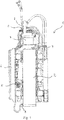
- Figur 1:
- eine Seitenansicht einer erfindungsgemäßen Rüttelvorrichtung.
- Man erkennt die Rüttelvorrichtung 1, eine Erregerzelle 2 und an der Erregerzelle 2 angeordnete Anschlüsse 3, 4 für einen Schmiermittelablauf bzw. eine Schmiermittelzufuhr. Von dem Anschluss 3 für einen Schmiermittelablauf erstreckt sich eine Leitung zur Pumpe 5, die für eine Umwälzung bzw. ein Zirkulieren des Schmiermittelkreislaufs verantwortlich ist.
- Von der Pumpe 5 verläuft der Schmiermittelkreislauf weiter zu einem Wärmetauscher 7, der mit einem Anschluss 4 für eine Schmiermittelzufuhr zur Erregerzelle 2 verbunden ist. Der Wärmetauscher 7 umfasst einen zweiten Kreislauf, der dazu geeignet ist, die Temperatur des Schmiermittelkreislaufs, der durch die Pumpe 5 und die Erregerzelle 2 fließt, zu beeinflussen. Der zweite Kreislauf wird durch die Versorgungsanschlüsse 8 von einer zur Rüttelvorrichtung externen Einheit gespeist und ist vorzugsweise mit dem Getriebeschmiermittelkreislauf des Baugeräts oder eines Power-Packs gekoppelt. Vorzugsweise entspricht der Getriebeschmiermittelkreislauf dem des Baugeräts, an dem die Rüttelvorrichtung angebracht ist. Alternativ sind die Versorgungsanschlüsse 8 auch mit einem Getriebeschmiermittelkreislauf eines Power-Packs verbindbar.
- Mit dem Bezugszeichen 6 ist das Ziehjoch der Rüttelvorrichtung 1 gekennzeichnet, der einen Eingriffsabschnitt mit dem Baugerät bzw. mit einem Mäkler des Baugeräts darstellt. In der dargestellten Ausführungsform ist die Pumpe 5 an dem Ziehjoch 6 angeordnet.
- Die Pumpe 5 zum Umwälzen des Schmiermittelkreislaufs der Rüttelvorrichtung 1 ist über eine separate Leitung 9 antreibbar. Dadurch kann sichergestellt werden, dass eine Umwälzung des Schmiermittelkreislaufs in der Rüttelvorrichtung 1 unabhängig von deren Betrieb durchführbar ist. Typischerweise ist die separate Leitung 9 mit dem Steuerdruck des Baugeräts oder des Power-Packs verbunden. Durch die in der
Fig. 1 wiedergegebene Konfiguration lassen sich sämtliche oben beschriebenen Vorteile erreichen.
Claims (10)
- Rüttelvorrichtung (1) zum Anbringen an eine Baumaschine, insbesondere an einen Mäkler einer Baumaschine, umfassend:eine Erregerzelle (2) zum Erzeugen einer Rüttelbewegung,einen Anschluss (3) für einen Ablauf von Schmiermittel der Erregerzelle (2),einen Anschluss (4) für eine Zufuhr von Schmiermittel in die Erregerzelle (2), undeine Pumpe (5) zum Fördern von Schmiermittel zwischen dem Anschluss (3) für einen Ablauf und dem Anschluss (4) für eine Zufuhr von Schmiermittel,dadurch gekennzeichnet, dassdie Pumpe (5) über eine separate Leitung (9), vorzugsweise eine Druckleitung, antreibbar ist.
- Rüttelvorrichtung (1) nach Anspruch 1, wobei die Pumpe (5) zum Antreiben eines Ölkreislaufs dient, der durch die Erregerzelle (2), den Anschluss (3) für einen Ölablauf, die Pumpe (5) und den Anschluss (4) für eine Ölzufuhr verläuft.
- Rüttelvorrichtung (1) nach einem der vorhergehenden Ansprüche, ferner umfassend ein Ziehjoch (6) zum Befestigen der Rüttelvorrichtung (1) an einem Baugerät, insbesondere an einem Mäkler eines Baugeräts, wobei die Pumpe (5) am Ziehjoch (6) angeordnet und/oder befestigt ist.
- Rüttelvorrichtung (1) nach einem der vorhergehenden Ansprüche, ferner umfassend:einen Wärmetauscher (7), insbesondere einen Plattentauscher, zum Regulieren der Temperatur des durch die Pumpe (5) förderbaren Öls, wobei vorzugsweisedie Pumpe (5) zum Antreiben eines Ölkreislaufs dient, der durch die Erregerzelle (2), den Anschluss (3) für einen Ölablauf, die Pumpe (5), den Wärmetauscher (7) und den Anschluss (4) für eine Ölzufuhr verläuft.
- Rüttelvorrichtung (1) nach Anspruch 4, wobei ein erster Kreislauf des Wärmetauschers (7) zum Durchströmen von durch die Pumpe (5) zu fördernden Öl ausgelegt ist, und ein zweiter Kreislauf des Wärmetauschers (7) dazu ausgelegt ist, mit einem Temperaturreguliermedium, insbesondere einer Hydraulikflüssigkeit, den ersten Kreislauf in seiner Temperatur zu regulieren.
- Rüttelvorrichtung (1) nach einem der Ansprüche 4 oder 5, wobei der zweite Kreislauf des Wärmetauschers (7) Versorgungsanschlüsse (8) für ein Zu- und ein Ablaufen eines Temperaturreguliermediums aufweist.
- Rüttelvorrichtung (1) nach einem der Ansprüche 5 bis 6, wobei der zweite Kreislauf des Wärmetauschers (7) mit einem Temperaturreguliermedium, insbesondere einem Öl oder Hydrauliköl, von einer zur Rüttelvorrichtung (1) separaten Einheit versorgt wird.
- Rüttelvorrichtung (1) nach einem der Ansprüche 5 bis 7, wobei die separate Einheit das Baugerät ist, an dem die Rüttelvorrichtung (1) anbringbar ist.
- Baugerät mit einer Rüttelvorrichtung (1) nach einem der vorhergehenden Ansprüche.
- Baugerät mit einer Rüttelvorrichtung (1) nach einem der Ansprüche 4 bis 8, wobei der zweite Kreislauf des Wärmetauschers (7) mit einem Temperaturreguliermedium, insbesondere einem Hydrauliköl, des Baugeräts versorgt wird.
Applications Claiming Priority (1)
| Application Number | Priority Date | Filing Date | Title |
|---|---|---|---|
| DE202015002714.8U DE202015002714U1 (de) | 2015-04-13 | 2015-04-13 | Rüttelvorrichtung |
Publications (3)
| Publication Number | Publication Date |
|---|---|
| EP3081700A1 EP3081700A1 (de) | 2016-10-19 |
| EP3081700B1 true EP3081700B1 (de) | 2018-06-13 |
| EP3081700B2 EP3081700B2 (de) | 2022-09-14 |
Family
ID=55699515
Family Applications (1)
| Application Number | Title | Priority Date | Filing Date |
|---|---|---|---|
| EP16164194.9A Active EP3081700B2 (de) | 2015-04-13 | 2016-04-07 | Rüttelvorrichtung |
Country Status (2)
| Country | Link |
|---|---|
| EP (1) | EP3081700B2 (de) |
| DE (1) | DE202015002714U1 (de) |
Citations (6)
| Publication number | Priority date | Publication date | Assignee | Title |
|---|---|---|---|---|
| FR2529292A1 (fr) | 1982-06-29 | 1983-12-30 | Procedes Tech Const | Dispositif de lubrification des organes en mouvement d'un appareil de foncage et /ou arrachage par vibration |
| US4861252A (en) | 1986-09-11 | 1989-08-29 | International Pipe Machinery Corp. | Vibrator type concrete pipe making machines having combined lubrication and cooling system |
| DE19628561C1 (de) | 1996-07-16 | 1997-09-04 | Laengerer & Reich Gmbh & Co | Plattenwärmetauscher |
| FR2775732B1 (fr) | 1998-03-06 | 2000-04-14 | Procedes Tech Const | Vibrateur a systeme de refrigeration permanente integre |
| EP1245737A2 (de) | 2001-03-28 | 2002-10-02 | BAUER Maschinen GmbH | Rüttler mit einem Hydraulikantrieb |
| WO2014147968A1 (ja) | 2013-03-19 | 2014-09-25 | 株式会社タダノ | 作業車両 |
Family Cites Families (2)
| Publication number | Priority date | Publication date | Assignee | Title |
|---|---|---|---|---|
| JP4543407B2 (ja) * | 2003-12-01 | 2010-09-15 | 調和工業株式会社 | 振動式杭打抜機 |
| EP1990100B1 (de) * | 2007-05-10 | 2009-09-16 | BAUER Maschinen GmbH | Baumaschine zum Erzeugen von Schwingungen |
-
2015
- 2015-04-13 DE DE202015002714.8U patent/DE202015002714U1/de not_active Expired - Lifetime
-
2016
- 2016-04-07 EP EP16164194.9A patent/EP3081700B2/de active Active
Patent Citations (6)
| Publication number | Priority date | Publication date | Assignee | Title |
|---|---|---|---|---|
| FR2529292A1 (fr) | 1982-06-29 | 1983-12-30 | Procedes Tech Const | Dispositif de lubrification des organes en mouvement d'un appareil de foncage et /ou arrachage par vibration |
| US4861252A (en) | 1986-09-11 | 1989-08-29 | International Pipe Machinery Corp. | Vibrator type concrete pipe making machines having combined lubrication and cooling system |
| DE19628561C1 (de) | 1996-07-16 | 1997-09-04 | Laengerer & Reich Gmbh & Co | Plattenwärmetauscher |
| FR2775732B1 (fr) | 1998-03-06 | 2000-04-14 | Procedes Tech Const | Vibrateur a systeme de refrigeration permanente integre |
| EP1245737A2 (de) | 2001-03-28 | 2002-10-02 | BAUER Maschinen GmbH | Rüttler mit einem Hydraulikantrieb |
| WO2014147968A1 (ja) | 2013-03-19 | 2014-09-25 | 株式会社タダノ | 作業車両 |
Non-Patent Citations (1)
| Title |
|---|
| "RTG Rammtchnik RG 18T Teleskopmäkler-Rammgerät Pile driver with telescopic leader", RTG, - April 2002 (2002-04-01), XP055565206 |
Also Published As
| Publication number | Publication date |
|---|---|
| EP3081700B2 (de) | 2022-09-14 |
| EP3081700A1 (de) | 2016-10-19 |
| DE202015002714U1 (de) | 2016-07-14 |
Similar Documents
| Publication | Publication Date | Title |
|---|---|---|
| EP3504433B1 (de) | Motor-pumpenvorrichtung | |
| DE112014007108T5 (de) | Elektrische Rotationsmaschine | |
| DE112021008055T5 (de) | Elektrische Antriebsanordnung für ein Fahrzeug | |
| DE3008828C2 (de) | Mehrfachziehbank zum Ziehen von Draht ohne Drahtschlupf | |
| DE102009035082A1 (de) | Getriebeölkreislauf | |
| DE102016004271A1 (de) | Verfahren zum Kühlen und/oder Aufheizen von Schmiermittel in einem Wechselfräswalzenkasten einer Bodenfräsmaschine, Wechselfräswalzenkasten und Bodenfräsmaschine | |
| EP3504455B1 (de) | Hydrodynamische kupplung | |
| DE112021008056T5 (de) | Elektroantrieb für ein Fahrzeug | |
| DE102013206500B4 (de) | Misch- und Fördergerät | |
| DE102020123590A1 (de) | Vorrichtung zur Fluidversorgung eines elektrischen Antriebstrangs | |
| EP3081700B1 (de) | Rüttelvorrichtung | |
| DE10303936A1 (de) | Hydraulischer Kreislauf und Spülvorrichtung | |
| DE112010001133B4 (de) | Schmiervorrichtung | |
| EP0691234B2 (de) | Verfahren und Einrichtung zur Kühlung mindestens einer Fahrpumpe und mindestens eines Fahrmotors eines hydrostatischen Fahrantriebes | |
| DE102020213773B4 (de) | Hydraulische Vorrichtung | |
| DE19603148C1 (de) | Verfahren zur Kühlung des Betriebsmittels in Antriebseinheiten für Förderanlagen, insbesondere Kettenförderanlagen und Antriebseinheit | |
| DE19512367A1 (de) | Antriebseinheit für Förderanlagen, insbesondere Bandantriebsanlage | |
| DE10327154B4 (de) | Verfahren zur Schmiermittelversorgung von Lagerbaueinheiten einer hydrodynamischen Kupplung und hydrodynamische Kupplung | |
| DE3829531C2 (de) | ||
| EP3215762B1 (de) | Antriebseinrichtung für ein kraftfahrzeug | |
| DE1628156A1 (de) | Gekapselter Motorverdichter,insbesondere fuer Kleinkaeltemaschinen | |
| DE102023206532A1 (de) | Getriebeanordnung für eine Arbeitsmaschine | |
| DE102023206537A1 (de) | Getriebeanordnung für eine Arbeitsmaschine | |
| EP4678947A1 (de) | Antriebsanordnung und ein fahrzeug mit einer antriebsanordnung | |
| DE102017111213A1 (de) | Betriebseinrichtung zum Betrieb einer Tunnelbohrvorrichtung sowie Verfahren zur Herstellung eines Tunnels |
Legal Events
| Date | Code | Title | Description |
|---|---|---|---|
| PUAI | Public reference made under article 153(3) epc to a published international application that has entered the european phase |
Free format text: ORIGINAL CODE: 0009012 |
|
| AK | Designated contracting states |
Kind code of ref document: A1 Designated state(s): AL AT BE BG CH CY CZ DE DK EE ES FI FR GB GR HR HU IE IS IT LI LT LU LV MC MK MT NL NO PL PT RO RS SE SI SK SM TR |
|
| AX | Request for extension of the european patent |
Extension state: BA ME |
|
| STAA | Information on the status of an ep patent application or granted ep patent |
Free format text: STATUS: REQUEST FOR EXAMINATION WAS MADE |
|
| 17P | Request for examination filed |
Effective date: 20170419 |
|
| GRAP | Despatch of communication of intention to grant a patent |
Free format text: ORIGINAL CODE: EPIDOSNIGR1 |
|
| STAA | Information on the status of an ep patent application or granted ep patent |
Free format text: STATUS: GRANT OF PATENT IS INTENDED |
|
| GRAJ | Information related to disapproval of communication of intention to grant by the applicant or resumption of examination proceedings by the epo deleted |
Free format text: ORIGINAL CODE: EPIDOSDIGR1 |
|
| GRAP | Despatch of communication of intention to grant a patent |
Free format text: ORIGINAL CODE: EPIDOSNIGR1 |
|
| INTG | Intention to grant announced |
Effective date: 20171024 |
|
| INTG | Intention to grant announced |
Effective date: 20171110 |
|
| GRAS | Grant fee paid |
Free format text: ORIGINAL CODE: EPIDOSNIGR3 |
|
| GRAA | (expected) grant |
Free format text: ORIGINAL CODE: 0009210 |
|
| STAA | Information on the status of an ep patent application or granted ep patent |
Free format text: STATUS: THE PATENT HAS BEEN GRANTED |
|
| AK | Designated contracting states |
Kind code of ref document: B1 Designated state(s): AL AT BE BG CH CY CZ DE DK EE ES FI FR GB GR HR HU IE IS IT LI LT LU LV MC MK MT NL NO PL PT RO RS SE SI SK SM TR |
|
| REG | Reference to a national code |
Ref country code: GB Ref legal event code: FG4D Free format text: NOT ENGLISH |
|
| REG | Reference to a national code |
Ref country code: CH Ref legal event code: EP Ref country code: AT Ref legal event code: REF Ref document number: 1008662 Country of ref document: AT Kind code of ref document: T Effective date: 20180615 |
|
| REG | Reference to a national code |
Ref country code: IE Ref legal event code: FG4D Free format text: LANGUAGE OF EP DOCUMENT: GERMAN |
|
| REG | Reference to a national code |
Ref country code: DE Ref legal event code: R096 Ref document number: 502016001218 Country of ref document: DE |
|
| REG | Reference to a national code |
Ref country code: NL Ref legal event code: FP |
|
| REG | Reference to a national code |
Ref country code: LT Ref legal event code: MG4D |
|
| PG25 | Lapsed in a contracting state [announced via postgrant information from national office to epo] |
Ref country code: FI Free format text: LAPSE BECAUSE OF FAILURE TO SUBMIT A TRANSLATION OF THE DESCRIPTION OR TO PAY THE FEE WITHIN THE PRESCRIBED TIME-LIMIT Effective date: 20180613 Ref country code: NO Free format text: LAPSE BECAUSE OF FAILURE TO SUBMIT A TRANSLATION OF THE DESCRIPTION OR TO PAY THE FEE WITHIN THE PRESCRIBED TIME-LIMIT Effective date: 20180913 Ref country code: BG Free format text: LAPSE BECAUSE OF FAILURE TO SUBMIT A TRANSLATION OF THE DESCRIPTION OR TO PAY THE FEE WITHIN THE PRESCRIBED TIME-LIMIT Effective date: 20180913 Ref country code: LT Free format text: LAPSE BECAUSE OF FAILURE TO SUBMIT A TRANSLATION OF THE DESCRIPTION OR TO PAY THE FEE WITHIN THE PRESCRIBED TIME-LIMIT Effective date: 20180613 Ref country code: SE Free format text: LAPSE BECAUSE OF FAILURE TO SUBMIT A TRANSLATION OF THE DESCRIPTION OR TO PAY THE FEE WITHIN THE PRESCRIBED TIME-LIMIT Effective date: 20180613 Ref country code: ES Free format text: LAPSE BECAUSE OF FAILURE TO SUBMIT A TRANSLATION OF THE DESCRIPTION OR TO PAY THE FEE WITHIN THE PRESCRIBED TIME-LIMIT Effective date: 20180613 Ref country code: CY Free format text: LAPSE BECAUSE OF FAILURE TO SUBMIT A TRANSLATION OF THE DESCRIPTION OR TO PAY THE FEE WITHIN THE PRESCRIBED TIME-LIMIT Effective date: 20180613 |
|
| PG25 | Lapsed in a contracting state [announced via postgrant information from national office to epo] |
Ref country code: RS Free format text: LAPSE BECAUSE OF FAILURE TO SUBMIT A TRANSLATION OF THE DESCRIPTION OR TO PAY THE FEE WITHIN THE PRESCRIBED TIME-LIMIT Effective date: 20180613 Ref country code: HR Free format text: LAPSE BECAUSE OF FAILURE TO SUBMIT A TRANSLATION OF THE DESCRIPTION OR TO PAY THE FEE WITHIN THE PRESCRIBED TIME-LIMIT Effective date: 20180613 Ref country code: GR Free format text: LAPSE BECAUSE OF FAILURE TO SUBMIT A TRANSLATION OF THE DESCRIPTION OR TO PAY THE FEE WITHIN THE PRESCRIBED TIME-LIMIT Effective date: 20180914 Ref country code: LV Free format text: LAPSE BECAUSE OF FAILURE TO SUBMIT A TRANSLATION OF THE DESCRIPTION OR TO PAY THE FEE WITHIN THE PRESCRIBED TIME-LIMIT Effective date: 20180613 |
|
| PG25 | Lapsed in a contracting state [announced via postgrant information from national office to epo] |
Ref country code: IS Free format text: LAPSE BECAUSE OF FAILURE TO SUBMIT A TRANSLATION OF THE DESCRIPTION OR TO PAY THE FEE WITHIN THE PRESCRIBED TIME-LIMIT Effective date: 20181013 Ref country code: PL Free format text: LAPSE BECAUSE OF FAILURE TO SUBMIT A TRANSLATION OF THE DESCRIPTION OR TO PAY THE FEE WITHIN THE PRESCRIBED TIME-LIMIT Effective date: 20180613 Ref country code: EE Free format text: LAPSE BECAUSE OF FAILURE TO SUBMIT A TRANSLATION OF THE DESCRIPTION OR TO PAY THE FEE WITHIN THE PRESCRIBED TIME-LIMIT Effective date: 20180613 Ref country code: CZ Free format text: LAPSE BECAUSE OF FAILURE TO SUBMIT A TRANSLATION OF THE DESCRIPTION OR TO PAY THE FEE WITHIN THE PRESCRIBED TIME-LIMIT Effective date: 20180613 Ref country code: RO Free format text: LAPSE BECAUSE OF FAILURE TO SUBMIT A TRANSLATION OF THE DESCRIPTION OR TO PAY THE FEE WITHIN THE PRESCRIBED TIME-LIMIT Effective date: 20180613 Ref country code: SK Free format text: LAPSE BECAUSE OF FAILURE TO SUBMIT A TRANSLATION OF THE DESCRIPTION OR TO PAY THE FEE WITHIN THE PRESCRIBED TIME-LIMIT Effective date: 20180613 |
|
| REG | Reference to a national code |
Ref country code: DE Ref legal event code: R026 Ref document number: 502016001218 Country of ref document: DE |
|
| PG25 | Lapsed in a contracting state [announced via postgrant information from national office to epo] |
Ref country code: SM Free format text: LAPSE BECAUSE OF FAILURE TO SUBMIT A TRANSLATION OF THE DESCRIPTION OR TO PAY THE FEE WITHIN THE PRESCRIBED TIME-LIMIT Effective date: 20180613 |
|
| PLBI | Opposition filed |
Free format text: ORIGINAL CODE: 0009260 |
|
| PLAX | Notice of opposition and request to file observation + time limit sent |
Free format text: ORIGINAL CODE: EPIDOSNOBS2 |
|
| 26 | Opposition filed |
Opponent name: BAUER MASCHINEN GMBH Effective date: 20190221 |
|
| PG25 | Lapsed in a contracting state [announced via postgrant information from national office to epo] |
Ref country code: DK Free format text: LAPSE BECAUSE OF FAILURE TO SUBMIT A TRANSLATION OF THE DESCRIPTION OR TO PAY THE FEE WITHIN THE PRESCRIBED TIME-LIMIT Effective date: 20180613 Ref country code: SI Free format text: LAPSE BECAUSE OF FAILURE TO SUBMIT A TRANSLATION OF THE DESCRIPTION OR TO PAY THE FEE WITHIN THE PRESCRIBED TIME-LIMIT Effective date: 20180613 |
|
| PLBB | Reply of patent proprietor to notice(s) of opposition received |
Free format text: ORIGINAL CODE: EPIDOSNOBS3 |
|
| PG25 | Lapsed in a contracting state [announced via postgrant information from national office to epo] |
Ref country code: AL Free format text: LAPSE BECAUSE OF FAILURE TO SUBMIT A TRANSLATION OF THE DESCRIPTION OR TO PAY THE FEE WITHIN THE PRESCRIBED TIME-LIMIT Effective date: 20180613 |
|
| REG | Reference to a national code |
Ref country code: CH Ref legal event code: PL |
|
| REG | Reference to a national code |
Ref country code: BE Ref legal event code: MM Effective date: 20190430 |
|
| PG25 | Lapsed in a contracting state [announced via postgrant information from national office to epo] |
Ref country code: LU Free format text: LAPSE BECAUSE OF NON-PAYMENT OF DUE FEES Effective date: 20190407 Ref country code: MC Free format text: LAPSE BECAUSE OF FAILURE TO SUBMIT A TRANSLATION OF THE DESCRIPTION OR TO PAY THE FEE WITHIN THE PRESCRIBED TIME-LIMIT Effective date: 20180613 |
|
| PG25 | Lapsed in a contracting state [announced via postgrant information from national office to epo] |
Ref country code: LI Free format text: LAPSE BECAUSE OF NON-PAYMENT OF DUE FEES Effective date: 20190430 Ref country code: CH Free format text: LAPSE BECAUSE OF NON-PAYMENT OF DUE FEES Effective date: 20190430 |
|
| PG25 | Lapsed in a contracting state [announced via postgrant information from national office to epo] |
Ref country code: BE Free format text: LAPSE BECAUSE OF NON-PAYMENT OF DUE FEES Effective date: 20190430 |
|
| PG25 | Lapsed in a contracting state [announced via postgrant information from national office to epo] |
Ref country code: TR Free format text: LAPSE BECAUSE OF FAILURE TO SUBMIT A TRANSLATION OF THE DESCRIPTION OR TO PAY THE FEE WITHIN THE PRESCRIBED TIME-LIMIT Effective date: 20180613 |
|
| PG25 | Lapsed in a contracting state [announced via postgrant information from national office to epo] |
Ref country code: IE Free format text: LAPSE BECAUSE OF NON-PAYMENT OF DUE FEES Effective date: 20190407 |
|
| PG25 | Lapsed in a contracting state [announced via postgrant information from national office to epo] |
Ref country code: PT Free format text: LAPSE BECAUSE OF FAILURE TO SUBMIT A TRANSLATION OF THE DESCRIPTION OR TO PAY THE FEE WITHIN THE PRESCRIBED TIME-LIMIT Effective date: 20181015 |
|
| GBPC | Gb: european patent ceased through non-payment of renewal fee |
Effective date: 20200407 |
|
| PG25 | Lapsed in a contracting state [announced via postgrant information from national office to epo] |
Ref country code: GB Free format text: LAPSE BECAUSE OF NON-PAYMENT OF DUE FEES Effective date: 20200407 |
|
| PG25 | Lapsed in a contracting state [announced via postgrant information from national office to epo] |
Ref country code: MT Free format text: LAPSE BECAUSE OF FAILURE TO SUBMIT A TRANSLATION OF THE DESCRIPTION OR TO PAY THE FEE WITHIN THE PRESCRIBED TIME-LIMIT Effective date: 20180613 Ref country code: HU Free format text: LAPSE BECAUSE OF FAILURE TO SUBMIT A TRANSLATION OF THE DESCRIPTION OR TO PAY THE FEE WITHIN THE PRESCRIBED TIME-LIMIT; INVALID AB INITIO Effective date: 20160407 |
|
| REG | Reference to a national code |
Ref country code: AT Ref legal event code: MM01 Ref document number: 1008662 Country of ref document: AT Kind code of ref document: T Effective date: 20210407 |
|
| PG25 | Lapsed in a contracting state [announced via postgrant information from national office to epo] |
Ref country code: MK Free format text: LAPSE BECAUSE OF FAILURE TO SUBMIT A TRANSLATION OF THE DESCRIPTION OR TO PAY THE FEE WITHIN THE PRESCRIBED TIME-LIMIT Effective date: 20180613 |
|
| PUAH | Patent maintained in amended form |
Free format text: ORIGINAL CODE: 0009272 |
|
| STAA | Information on the status of an ep patent application or granted ep patent |
Free format text: STATUS: PATENT MAINTAINED AS AMENDED |
|
| PG25 | Lapsed in a contracting state [announced via postgrant information from national office to epo] |
Ref country code: AT Free format text: LAPSE BECAUSE OF NON-PAYMENT OF DUE FEES Effective date: 20210407 |
|
| 27A | Patent maintained in amended form |
Effective date: 20220914 |
|
| AK | Designated contracting states |
Kind code of ref document: B2 Designated state(s): AL AT BE BG CH CY CZ DE DK EE ES FI FR GB GR HR HU IE IS IT LI LT LU LV MC MK MT NL NO PL PT RO RS SE SI SK SM TR |
|
| REG | Reference to a national code |
Ref country code: DE Ref legal event code: R102 Ref document number: 502016001218 Country of ref document: DE |
|
| REG | Reference to a national code |
Ref country code: NL Ref legal event code: FP |
|
| P01 | Opt-out of the competence of the unified patent court (upc) registered |
Effective date: 20230630 |
|
| PGFP | Annual fee paid to national office [announced via postgrant information from national office to epo] |
Ref country code: NL Payment date: 20250426 Year of fee payment: 10 |
|
| PGFP | Annual fee paid to national office [announced via postgrant information from national office to epo] |
Ref country code: DE Payment date: 20250430 Year of fee payment: 10 |
|
| PGFP | Annual fee paid to national office [announced via postgrant information from national office to epo] |
Ref country code: IT Payment date: 20250428 Year of fee payment: 10 |
|
| PGFP | Annual fee paid to national office [announced via postgrant information from national office to epo] |
Ref country code: FR Payment date: 20250426 Year of fee payment: 10 |